EP3694741B1 - Train traction system - Google Patents
Train traction system Download PDFInfo
- Publication number
- EP3694741B1 EP3694741B1 EP18867057.4A EP18867057A EP3694741B1 EP 3694741 B1 EP3694741 B1 EP 3694741B1 EP 18867057 A EP18867057 A EP 18867057A EP 3694741 B1 EP3694741 B1 EP 3694741B1
- Authority
- EP
- European Patent Office
- Prior art keywords
- switches
- electric power
- train
- traction system
- converters
- Prior art date
- Legal status (The legal status is an assumption and is not a legal conclusion. Google has not performed a legal analysis and makes no representation as to the accuracy of the status listed.)
- Active
Links
Images


Classifications
-
- B—PERFORMING OPERATIONS; TRANSPORTING
- B60—VEHICLES IN GENERAL
- B60L—PROPULSION OF ELECTRICALLY-PROPELLED VEHICLES; SUPPLYING ELECTRIC POWER FOR AUXILIARY EQUIPMENT OF ELECTRICALLY-PROPELLED VEHICLES; ELECTRODYNAMIC BRAKE SYSTEMS FOR VEHICLES IN GENERAL; MAGNETIC SUSPENSION OR LEVITATION FOR VEHICLES; MONITORING OPERATING VARIABLES OF ELECTRICALLY-PROPELLED VEHICLES; ELECTRIC SAFETY DEVICES FOR ELECTRICALLY-PROPELLED VEHICLES
- B60L15/00—Methods, circuits, or devices for controlling the traction-motor speed of electrically-propelled vehicles
- B60L15/20—Methods, circuits, or devices for controlling the traction-motor speed of electrically-propelled vehicles for control of the vehicle or its driving motor to achieve a desired performance, e.g. speed, torque, programmed variation of speed
- B60L15/22—Methods, circuits, or devices for controlling the traction-motor speed of electrically-propelled vehicles for control of the vehicle or its driving motor to achieve a desired performance, e.g. speed, torque, programmed variation of speed with sequential operation of interdependent switches, e.g. relays, contactors or program drum
-
- B—PERFORMING OPERATIONS; TRANSPORTING
- B60—VEHICLES IN GENERAL
- B60L—PROPULSION OF ELECTRICALLY-PROPELLED VEHICLES; SUPPLYING ELECTRIC POWER FOR AUXILIARY EQUIPMENT OF ELECTRICALLY-PROPELLED VEHICLES; ELECTRODYNAMIC BRAKE SYSTEMS FOR VEHICLES IN GENERAL; MAGNETIC SUSPENSION OR LEVITATION FOR VEHICLES; MONITORING OPERATING VARIABLES OF ELECTRICALLY-PROPELLED VEHICLES; ELECTRIC SAFETY DEVICES FOR ELECTRICALLY-PROPELLED VEHICLES
- B60L15/00—Methods, circuits, or devices for controlling the traction-motor speed of electrically-propelled vehicles
- B60L15/32—Control or regulation of multiple-unit electrically-propelled vehicles
-
- B—PERFORMING OPERATIONS; TRANSPORTING
- B60—VEHICLES IN GENERAL
- B60L—PROPULSION OF ELECTRICALLY-PROPELLED VEHICLES; SUPPLYING ELECTRIC POWER FOR AUXILIARY EQUIPMENT OF ELECTRICALLY-PROPELLED VEHICLES; ELECTRODYNAMIC BRAKE SYSTEMS FOR VEHICLES IN GENERAL; MAGNETIC SUSPENSION OR LEVITATION FOR VEHICLES; MONITORING OPERATING VARIABLES OF ELECTRICALLY-PROPELLED VEHICLES; ELECTRIC SAFETY DEVICES FOR ELECTRICALLY-PROPELLED VEHICLES
- B60L9/00—Electric propulsion with power supply external to the vehicle
- B60L9/005—Interference suppression
-
- B—PERFORMING OPERATIONS; TRANSPORTING
- B60—VEHICLES IN GENERAL
- B60L—PROPULSION OF ELECTRICALLY-PROPELLED VEHICLES; SUPPLYING ELECTRIC POWER FOR AUXILIARY EQUIPMENT OF ELECTRICALLY-PROPELLED VEHICLES; ELECTRODYNAMIC BRAKE SYSTEMS FOR VEHICLES IN GENERAL; MAGNETIC SUSPENSION OR LEVITATION FOR VEHICLES; MONITORING OPERATING VARIABLES OF ELECTRICALLY-PROPELLED VEHICLES; ELECTRIC SAFETY DEVICES FOR ELECTRICALLY-PROPELLED VEHICLES
- B60L2200/00—Type of vehicles
- B60L2200/26—Rail vehicles
-
- B—PERFORMING OPERATIONS; TRANSPORTING
- B60—VEHICLES IN GENERAL
- B60L—PROPULSION OF ELECTRICALLY-PROPELLED VEHICLES; SUPPLYING ELECTRIC POWER FOR AUXILIARY EQUIPMENT OF ELECTRICALLY-PROPELLED VEHICLES; ELECTRODYNAMIC BRAKE SYSTEMS FOR VEHICLES IN GENERAL; MAGNETIC SUSPENSION OR LEVITATION FOR VEHICLES; MONITORING OPERATING VARIABLES OF ELECTRICALLY-PROPELLED VEHICLES; ELECTRIC SAFETY DEVICES FOR ELECTRICALLY-PROPELLED VEHICLES
- B60L2210/00—Converter types
- B60L2210/20—AC to AC converters
-
- B—PERFORMING OPERATIONS; TRANSPORTING
- B60—VEHICLES IN GENERAL
- B60L—PROPULSION OF ELECTRICALLY-PROPELLED VEHICLES; SUPPLYING ELECTRIC POWER FOR AUXILIARY EQUIPMENT OF ELECTRICALLY-PROPELLED VEHICLES; ELECTRODYNAMIC BRAKE SYSTEMS FOR VEHICLES IN GENERAL; MAGNETIC SUSPENSION OR LEVITATION FOR VEHICLES; MONITORING OPERATING VARIABLES OF ELECTRICALLY-PROPELLED VEHICLES; ELECTRIC SAFETY DEVICES FOR ELECTRICALLY-PROPELLED VEHICLES
- B60L2210/00—Converter types
- B60L2210/30—AC to DC converters
-
- B—PERFORMING OPERATIONS; TRANSPORTING
- B60—VEHICLES IN GENERAL
- B60L—PROPULSION OF ELECTRICALLY-PROPELLED VEHICLES; SUPPLYING ELECTRIC POWER FOR AUXILIARY EQUIPMENT OF ELECTRICALLY-PROPELLED VEHICLES; ELECTRODYNAMIC BRAKE SYSTEMS FOR VEHICLES IN GENERAL; MAGNETIC SUSPENSION OR LEVITATION FOR VEHICLES; MONITORING OPERATING VARIABLES OF ELECTRICALLY-PROPELLED VEHICLES; ELECTRIC SAFETY DEVICES FOR ELECTRICALLY-PROPELLED VEHICLES
- B60L2210/00—Converter types
- B60L2210/40—DC to AC converters
-
- B—PERFORMING OPERATIONS; TRANSPORTING
- B60—VEHICLES IN GENERAL
- B60L—PROPULSION OF ELECTRICALLY-PROPELLED VEHICLES; SUPPLYING ELECTRIC POWER FOR AUXILIARY EQUIPMENT OF ELECTRICALLY-PROPELLED VEHICLES; ELECTRODYNAMIC BRAKE SYSTEMS FOR VEHICLES IN GENERAL; MAGNETIC SUSPENSION OR LEVITATION FOR VEHICLES; MONITORING OPERATING VARIABLES OF ELECTRICALLY-PROPELLED VEHICLES; ELECTRIC SAFETY DEVICES FOR ELECTRICALLY-PROPELLED VEHICLES
- B60L2240/00—Control parameters of input or output; Target parameters
- B60L2240/80—Time limits
-
- B—PERFORMING OPERATIONS; TRANSPORTING
- B60—VEHICLES IN GENERAL
- B60L—PROPULSION OF ELECTRICALLY-PROPELLED VEHICLES; SUPPLYING ELECTRIC POWER FOR AUXILIARY EQUIPMENT OF ELECTRICALLY-PROPELLED VEHICLES; ELECTRODYNAMIC BRAKE SYSTEMS FOR VEHICLES IN GENERAL; MAGNETIC SUSPENSION OR LEVITATION FOR VEHICLES; MONITORING OPERATING VARIABLES OF ELECTRICALLY-PROPELLED VEHICLES; ELECTRIC SAFETY DEVICES FOR ELECTRICALLY-PROPELLED VEHICLES
- B60L2270/00—Problem solutions or means not otherwise provided for
- B60L2270/10—Emission reduction
- B60L2270/14—Emission reduction of noise
- B60L2270/147—Emission reduction of noise electro magnetic [EMI]
-
- B—PERFORMING OPERATIONS; TRANSPORTING
- B60—VEHICLES IN GENERAL
- B60L—PROPULSION OF ELECTRICALLY-PROPELLED VEHICLES; SUPPLYING ELECTRIC POWER FOR AUXILIARY EQUIPMENT OF ELECTRICALLY-PROPELLED VEHICLES; ELECTRODYNAMIC BRAKE SYSTEMS FOR VEHICLES IN GENERAL; MAGNETIC SUSPENSION OR LEVITATION FOR VEHICLES; MONITORING OPERATING VARIABLES OF ELECTRICALLY-PROPELLED VEHICLES; ELECTRIC SAFETY DEVICES FOR ELECTRICALLY-PROPELLED VEHICLES
- B60L2270/00—Problem solutions or means not otherwise provided for
- B60L2270/20—Inrush current reduction, i.e. avoiding high currents when connecting the battery
-
- Y—GENERAL TAGGING OF NEW TECHNOLOGICAL DEVELOPMENTS; GENERAL TAGGING OF CROSS-SECTIONAL TECHNOLOGIES SPANNING OVER SEVERAL SECTIONS OF THE IPC; TECHNICAL SUBJECTS COVERED BY FORMER USPC CROSS-REFERENCE ART COLLECTIONS [XRACs] AND DIGESTS
- Y02—TECHNOLOGIES OR APPLICATIONS FOR MITIGATION OR ADAPTATION AGAINST CLIMATE CHANGE
- Y02T—CLIMATE CHANGE MITIGATION TECHNOLOGIES RELATED TO TRANSPORTATION
- Y02T10/00—Road transport of goods or passengers
- Y02T10/60—Other road transportation technologies with climate change mitigation effect
- Y02T10/64—Electric machine technologies in electromobility
-
- Y—GENERAL TAGGING OF NEW TECHNOLOGICAL DEVELOPMENTS; GENERAL TAGGING OF CROSS-SECTIONAL TECHNOLOGIES SPANNING OVER SEVERAL SECTIONS OF THE IPC; TECHNICAL SUBJECTS COVERED BY FORMER USPC CROSS-REFERENCE ART COLLECTIONS [XRACs] AND DIGESTS
- Y02—TECHNOLOGIES OR APPLICATIONS FOR MITIGATION OR ADAPTATION AGAINST CLIMATE CHANGE
- Y02T—CLIMATE CHANGE MITIGATION TECHNOLOGIES RELATED TO TRANSPORTATION
- Y02T10/00—Road transport of goods or passengers
- Y02T10/60—Other road transportation technologies with climate change mitigation effect
- Y02T10/72—Electric energy management in electromobility
Definitions
- the present disclosure relates to a traction system for a train.
- railway lines often have electrical trackside safety and communication equipment used to transmit information (e.g. speed restrictions, stop locations etc.) to traffic on the lines in order to prevent unsafe train operation and thereby avoid accidents.
- information e.g. speed restrictions, stop locations etc.
- Electric-powered trains using such lines typically have a traction system which converts electric power provided from an overhead wire to suitable AC power for one or more traction motors mounted on the trains.
- the traction systems may include AC/DC converters.
- PWM converters are in widespread use, the PWM converter comprising bridge-connected diodes, with each diode having a self-extinction type switching element (e.g. an IGBT) connected in inverse-parallel thereto.
- GB A 2527881 and GB A 2537732 propose addressing this problem by adopting plural AC/DC converters which have the same PWM switching frequency but which are operated so that the PWM carrier waves (i.e. pulse signals) of the respective converters are phase shifted from each other in order to cancel out each other's second order harmonic noise (i.e. noise at twice the frequency of the pulse signals), and hence reduce the noise signal flowing into the rails.
- US 5642020 proposes an electric vehicle control device wherein electric motors are driven by PWM converters and inverters.
- Document JPH0583803 relates to an electric vehicle control apparatus for controlling an electric vehicle driving motor using a variable voltage-frequency inverter.
- the traction system typically further includes transformer equipment for stepping down the electric voltage level from the high voltage of the overhead wire, the AC/DC converters operating on the stepped down voltage to convert it to DC, which is then further manipulated to provide AC power for the motors.
- transformer equipment for stepping down the electric voltage level from the high voltage of the overhead wire
- the AC/DC converters operating on the stepped down voltage to convert it to DC, which is then further manipulated to provide AC power for the motors.
- an inrush current flows into the transformer equipment from the power source, resulting in another noise current.
- the individual noise currents can reinforce each other to such an extent that operation of the trackside safety and communication equipment can be compromised.
- the present invention aims to address such problems.
- an aim is to reduce noise created by the traction system and thereby reduce the risk of compromising the operation of trackside safety and communication equipment.
- the present invention aims to address the technical problem of minimising the noise current caused by interference of the inrush currents supplied from the power source to the plurality of transformers via the overhead line, and suppressing higher-order harmonics in the harmonic noise generated by the AC/DC converters via phase shifting.
- the present invention provides a traction system for a train according to claim 1.
- the present invention provides a train having the traction system of the first embodiment.
- the present invention provides a train set including first and second coupled trains, each according to the second embodiment, wherein the controllers of the coupled trains are further configured such that the start of the sequential closing of the first switches of the second train occurs a further predetermined time interval after the completion of the sequential closing of the first switches of the first train.
- the controllers of the coupled trains may be further configured such that the power conversion using pulse width modulation by the AC/DC converters of the first train is started before completion of the sequential closing of the first switches of the second train.
- the present invention provides respective uses of the traction system, train and train set of the first to third embodiments and respective methods of operating the traction system, train and train set of the first to third embodiments. For example, a method of operating a traction system for a train according to claim 12 is provided.
- the system may have three or more of the converter units.
- at least three AC/DC converters are needed to use phase shifting to cancel out second order harmonic noise.
- the system may have two or more of the transformers.
- one transformer may provide stepped down AC electric power to more than one converter unit.
- the first predetermined time interval may be selected such that the inrush current provoked by the closing of a previous first switch peaks before a next first switch closes.
- the traction system may have: plural second switches which are closable to respectively connect the AC/DC converters to low voltage sides of the transformers.
- the controller may then be further configured to control: the timing of the closing of the second switches such that each second switch closes a second predetermined time interval after the first switch which connects the high voltage sides of the respective transformer to the overhead wire has closed; and the timing of the start of power conversion using pulse width modulation by each of the AC/DC converters such that the starts are simultaneous and after the first and the second switches have closed.
- the traction system may have: one or more pantographs for obtaining the AC electric power from the overhead wire; a power line which connects the overhead wire sides of the first switches; and one or more third switches which are closable to respectively connect the one or more pantographs to the power line.
- the controller may then be further configured to control the timing of the closing of the one or more third switches such that the one or more third switches close before the start of the sequential closing of the first switches.
- Each converter unit further includes an inverter for converting the DC electric power provided by the AC/DC convertor to multiphase AC electric power.
- Each converter unit may then further include a smoothing capacitor between the AC/DC convertor and the inverter.
- the traction system may further have plural traction motors driven by the multiphase AC electric power provided by the converter units.
- Figure 1 shows schematically the structure of a first traction system.
- the system is located in a train made up of nine cars (Cars 1-9).
- Cars 2, 3, 5, 7 and 8 each have a traction converter (CNV) unit 1 and a traction motor 4 powered by the CNV unit to drive the train.
- Cars 1, 4, 6 and 9 are without CNV units and traction motors, but Cars 1, 4 and 9 each have transformer equipment 2, and Cars 1 and 9 also each have a pantograph 3 for collecting high voltage AC electric power from an overhead wire.
- the high voltage sides of the transformer equipment are connected by a power line 8 which extends from Car 1 to Car 9.
- the AC power collected by the pantographs 3 is provided to the transformer equipment 2 and then, as stepped down AC power, to the CNV units.
- the CNV units 1 convert this stepped down single-phase AC power to three-phase AC power, and provide the three-phase power to the motors 4.
- the flow of power through the system is controlled by first breaker switches 6, second breaker switches 7 and third breaker switches 5.
- the third breaker switches 5 are closable to respectively connect the pantographs to the power line 8.
- the first breaker switches 6 are closable to connect the high voltage sides of the transformer equipment 2 to the overhead wire power line 8 and thence the overhead wire.
- the second breaker switches 7 are closable to connect the CNV units 1 to the low voltage sides of the transformer equipment 2.
- each car having a pantograph 3 has a third breaker switch 5
- each car having transformer equipment 2 has a first breaker switch 6, and each car having a CNV unit 1 has a second breaker switch 7.
- FIG. 2 shows schematically more detail of the structure of the CNV unit 1.
- the CNV unit 1 comprises a PWM-operated AC/DC converter 101 which converts the stepped down AC power to DC power, an inverter 103 which converts the DC power to multiphase AC power with a variable voltage and frequency and provides the AC power to a traction motor 4, and a smoothing capacitor or condenser 102 connected between the AC/DC converter and the inverter to smooth DC voltage.
- Figure 3 shows schematically how the PWM-operation of the CNV units 1 can be phase shifted to cancel out second order harmonic noise.
- the following phase differences can be set for the PWM pulse signals of the five AC/DC converters 101 of the CNV units: Car 2: 144°, Car 3: 108°, Car 5: 72°, Car 7: 36°, Car 8: 0°.
- These phase differences correspond to a 36° car-to-car shift, and can be set relative to the zero-crossing point of the input stepped down AC power (which has, typically, a 50 Hz frequency) as this is a reference available to all the CNV units. Further details can be found in GB A 2527881 and GB A 2537732 .
- Figure 4 shows schematically functions of a control unit 9 for controlling the traction system.
- the control unit 9 ca be mounted on any car of the train.
- Command signals (open/close) for the first 6 and third 5 breaker switches can be sent directly to the respective switch from the control unit.
- Command signals for the second breaker switch 7 can also be sent to the respective switches from the control unit, but typically via the respective CNV unit 1.
- the control unit 9 collects switch status directory information (open/close) directly from the switches or via communication with the CNV units.
- the control unit also sends command signals to the CNV units 1 to start/stop power conversion, and collects operation status information (operating/non-operating) from the CNV units by communication therewith.
- FIG. 5 shows a comparative example first starting sequence for the transformers 2 and the CNV units 1 of the system of Figure 1 , as controlled by the control unit 9.
- First one of the pantograph 3 mounted on Cars 1 and 9 is deployed and made ready to collect electrical power from the overhead wire (stand-by condition).
- its third breaker switch 5 is closed (t0).
- a predetermined time e.g. 1 sec
- the three first breakers switches 6 mounted in Cars 1, 4, and 9 are closed (t1). This causes an inrush current flow into the three transformers 2, and a corresponding noise current is created.
- Another predetermined time e.g.
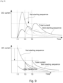
- This first starting sequence makes it possible to reduce harmonic noise from the pulse signals immediately the AC/DC converters 101 commence their switching operation because all the multiple CNV units are made ready to start at the same time.
- the three transformers 2 are connected to the AC power source at the same time (t1) and provoke simultaneous inrush currents.
- t1 the AC power source
- both the DC and AC components of the combined noise currents created by the inrush currents superimpose on each other.
- the peak noise current can be three times higher than that created by the connection of a single transformer.
- Figure 7 shows a comparative example second starting sequence for the transformers 2 and the CNV units 1 of the system of Figure 1 .
- This sequence can avoid some of the worst effects of the superposition of the noise currents created by the inrush currents of the transformers 2.
- one of the pantographs 3 mounted on Cars 1 and 9 is deployed and made ready to collect electrical power from the overhead wire (stand-by condition).
- its third breaker switch 5 is closed (t0).
- a predetermined time e.g. 1 sec
- the first breaker switch 6 mounted in Car 1 is closed (t1). This causes an inrush current flow into its transformer 2, and a corresponding noise current is created.
- Another predetermined time (e.g. 1 sec) after the closure of the first breaker switch, the second breaker switches 7 in Cars 2 and 3 for the respective CNV units 1 of those cars are closed (t2).
- the second breaker switches of Cars 2 and 3 are closed, DC current flows into the capacitors 102 of their CNV units through the diode elements of the AC/DC converters 101, and the capacitors charge up and their voltage increases.
- Yet another predetermined time e.g. 1 sec) after the closures of the second breaker switches of Cars 2 and 3, the AC/DC converters 101 of Cars 2 and 3 start their switching operations with the above-mentioned (36°) phase shifts in their PWM pulse signals (t3).
- Another predetermined time (e.g. 2 sec) after the first breaker switch 6 of Car 1 is closed, the first breaker switch 6 mounted in Car 9 is closed (t3). This causes an inrush current flow into its transformer 2, and a corresponding noise current is created.
- a predetermined time (e.g. 1 sec) after the closure of the first breaker switch, the second breaker switches 7 in Cars 7 and 8 for the respective CNV units 1 of those cars are closed (t4).
- the second breaker switches of Cars 7 and 8 are closed, DC current flows into the capacitors 102 through the diode elements of the AC/DC converters 101, and the capacitors charge up and their voltage increases.
- Yet another predetermined time (e.g. 1 sec) after the closures of the second breaker switches of Cars 7 and 8, the AC/DC converters 101 of Cars 7 and 8 start their switching operations with the phase shifts in their PWM pulse signals (t5).
- the transformers 2 can be connected to the AC power source at different times with predetermined time intervals therebetween. Hence, it is possible to reduce the amount of overlap of the noise currents created by their respective inrush currents. In this way the peak level of the combined noise currents can be reduced.
- the timings of the start-ups of the AC/DC converters 101 vary between the converters (t3, t5, t7). Hence, the phase difference harmonic noise reduction does not work well during the period from t2 to t7 when only some of the AC/DC converters 101 are operating. In particular, when only the AC/DC converters 101 of Cars 2 and 3 are operating, the second order harmonic noise is greatly increased.
- Figure 8 shows an example third starting sequence for the transformers 2 and the CNV units 1 of the system of Figure 1 .
- This sequence can avoid some of the worst effects of the superposition of the noise currents created by the inrush currents of the transformers 2, and also can reduce second order harmonic noise from the CNV units 1.
- one of the pantographs 3 mounted on Cars 1 and 9 is deployed and made ready to collect electrical power from the overhead wire (stand-by condition).
- its third breaker switch 5 is closed (t0).
- a predetermined time e.g. 1 sec
- the first breaker switch 6 mounted in Car 1 is closed (t1).
- Another predetermined time (e.g. 2 sec) after the first breaker switch 6 of Car 1 is closed, the first breaker switch 6 mounted in Car 9 is closed (t3). This causes an inrush current flow into its transformer 2, and a corresponding noise current is created.
- a predetermined time (e.g. 1 sec) after the closure of the first breaker switch, the second breaker switches 7 in Cars 7 and 8 for the respective CNV units 1 of those cars are closed (t4).
- the second breaker switches of Cars 7 and 8 are closed, DC current flows into the capacitors 102 through the diode elements of the AC/DC converters 101, and the capacitors charge up and their voltage increases.
- the start of switching operations of the AC/DC converters 101 of Cars 7 and 8 is delayed.
- Yet another predetermined time (e.g. 2 sec) after the first breaker switch 6 of Car 9 is closed, the first breaker switch 6 mounted in Car 4 is closed (t5). This causes an inrush current flow into its transformer 2, and a corresponding noise current is created.
- a predetermined time (e.g. 1 sec) after the closure of the first breaker switch, the second breaker switch 7 in Car 5 is closed (t6). When the second breaker switch of Car 5 is closed, DC current flows into the capacitor 102 of its CNV unit through the diode elements of the AC/DC converter 101, and the capacitor charges up and its voltage increases.
- a further predetermined time e.g. 2 sec
- the control unit commands the AC/DC converters 101 of all of Cars 2, 3, 5, 7 and 8 simultaneously to start their phase-shifted switching operations (t7).
- t7 phase-shifted switching operations
- the transformers 2 are connected to the AC power source in a sequential order with a two second time interval between closures of the first breaker switches 6.
- the time interval between first breaker switch closures can be set to be longer than the time period over which the level of DC and AC noise current reduces by a suitable amount.
- the time interval can be such that the inrush current, and hence the noise current, provoked by the previous switch closure has peaked before the next switch closure occurs.
- Figure 10 shows schematically the structure of a second traction system.
- the system is located in a train made up of five cars (Cars 1-5).
- Cars 2, 3 and 4 each have a traction converter (CNV) unit 1 and a traction motor 4 powered by the CNV unit to drive the train.
- Cars 1 and 9 are without CNV units and traction motors, but each have transformer equipment 2 and a pantograph 3 for collecting high voltage AC electric power from an overhead wire. Again, the high voltage sides of the transformer equipment are connected by a power line 8 which extends from Car 1 to Car 5.
- CNV traction converter
- Figure 11 shows schematically how the phase shifted PWM-operation of the CNV units 1 cancel out second order harmonic noise.
- the following phase differences corresponding to a 60° car-to-car shift, can be set for the PWM pulse signals of the three AC/DC converters 101 of the CNV units: Car 2: 120°, Car 3: 60°, Car 4: 0°.
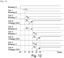
- FIG 12 shows a comparative example fourth starting sequence for the transformers 2 and the CNV units 1 of the system of Figure 10 as controlled by its control unit 9.
- this starting up sequence it is possible to avoid the overlapping of noise current from the transformers created by their respective inrush currents.
- the transformers 2 are connected to the AC power source at different times (i.e. t1 and t3).
- the starting up timing (t3) of the AC/DC converter 101 mounted on Car 2 is earlier than the starting up timings (t5) of the AC/DC converters 101 mounted on Cars 3 and 4.
- the harmonic noise from the AC/DC converter (101) of Car 2 cannot be cancelled.
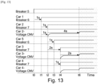
- Figure 13 shows a fifth starting sequence for the transformers 2 and the CNV units 1 of the system of Figure 10 .
- this starting up sequence it is possible to avoid the overlapping of noise current from the transformers 2, and to reduce harmonic noise from the CNV units 1.
- one of the pantographs 3 mounted on Cars 1 and 5 is deployed and made ready to collect electrical power from the overhead wire (stand-by condition).
- its third breaker switch 5 is closed (t0).
- a predetermined time e.g. 1 sec
- the first breaker switch 6 mounted in Car 1 is closed (t1). This causes an inrush current flow into its transformer 2, and a corresponding noise current is created.
- Another predetermined time e.g. 1 sec) after the closure of the first breaker switch, the second breaker switch 7 in Car 2 for the CNV unit 1 of that car is closed (t2).
- Another predetermined time (e.g. 2 sec) after the first breaker switch 6 of Car 1 is closed, the first breaker switch 6 mounted in Car 5 is closed (t3). This causes an inrush current flow into its transformer 2, and a corresponding noise current is created.
- a predetermined time (e.g. 1 sec) after the closure of the first breaker switch, the second breaker switches 7 in Cars 3 and 4 for the respective CNV units 1 of those cars are closed (t4).
- the second breaker switches of Cars 3 and 4 are closed, DC current flows into the capacitors 102 through the diode elements of the AC/DC converters 101, and the capacitors charge up and their voltage increases.
- the transformers 2 are connected with the AC power source at different times with a predetermined time interval therebetween.
- the fifth starting sequence it is possible with the fifth starting sequence to reduce the amount of overlap of the noise currents created by their respective inrush currents.
- the peak level of the combined noise currents can be reduced.
- the peak levels of both the DC and AC components of the combined noise currents created by the inrush currents can be decreased relative to the DC and AC components of the combined noise currents that would occur under the fourth starting sequence.
- a further predetermined time e.g. 2 sec
- the control unit commands the AC/DC converters 101 of all of Cars 2, 3 and 4 to start simultaneously their phase-shifted switching operations (t6). In this way it is possible to reduce second (and fourth and eighth) order harmonic noise from the pulse signals even when the AC/DC converters 101 are starting up.
- FIG 15 shows schematically the structures of two traction systems. Each system is located in a respective train (T1 and T2) made up of five cars (Cars 1-5). The two trains are mechanically coupled to form a train set, but the each traction system is electrically independent from the other. The two traction systems are identical to each and are the same as the traction system described above in relation to Figure 10 .
- Figure 16 shows schematically how the phase shifted PWM-operation of the CNV units 1 cancel out second order harmonic noise.
- the following phase differences corresponding to a 60° car-to-car shift, can be set for the PWM pulse signals of the three AC/DC converters 101 of the CNV units of T1: Car 2: 120°, Car 3: 60°, Car 4: 0°.
- the following phase differences, corresponding to a 60° car-to-car shift can be set for the PWM pulse signals of the three AC/DC converters 101 of the CNV units of T2: Car 2: 150°, Car 3: 90°, Car 4: 30°.
- the traction system of each train is thus set up to cancel out second order harmonic noise.
- FIG 17 shows a possible sixth starting sequence for the transformers 2 and the CNV units 1 of the systems of Figure 15 as controlled by their respective control units 9.
- this starting up sequence it is possible to avoid overlapping of noise current from the transformers created by their respective inrush currents.
- the transformers are connected to the AC power source at different times (t1, t3, t5 and t7).
- the starting up timing (t3) of the AC/DC converter 101 mounted on T1 Car 2 is earlier than the starting up timings (t5) of the AC/DC converters 101 mounted on T1 Cars 3 and 4.
- the starting up timing (t7) of the AC/DC converter 101 mounted on T2 Car 2 is earlier than the starting up timings (t9) of the AC/DC converters 101 mounted on T2 Cars 3 and 4.
- the harmonic noise from the AC/DC converter (101) of T1 Car 2 cannot be cancelled
- the harmonic noise from the AC/DC converter (101) of T2 Car 2 cannot be cancelled.
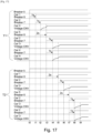
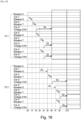
- Figure 18 shows a possible seventh starting sequence for the transformers 2 and the CNV units 1 of the systems of Figure 15 .
- this starting up sequence it is possible to avoid the overlapping of noise current from the transformers 2, and to reduce harmonic noise from the CNV units 1.
- one of the pantographs 3 mounted on T1 Cars 1 and 5 is deployed and one of the pantographs 3 mounted on T2 Cars 1 and 5 is deployed, and both are made ready to collect electrical power from the overhead wire (stand-by condition).
- their third breaker switches 5 are closed (t0).
- a predetermined time e.g. 1 sec
- the first breaker switch 6 mounted in T1 Car 1 is closed (t1). This causes an inrush current flow into its transformer 2, and a corresponding noise current is created.
- a predetermined time e.g. 1 sec
- the second breaker switch 7 in T1 Car 2 for the CNV unit 1 of that car is closed (t2).
- DC current flows into the capacitor 102 of its CNV unit through the diode elements of the AC/DC converter 101, and the capacitor charges up and its voltage increases.
- the start of switching operations of the AC/DC converter 101 of T1 Car 2 is delayed.
- Another predetermined time (e.g. 2 sec) after the first breaker switch 6 of T1 Car 1 is closed, the first breaker switch 6 mounted in T1 Car 5 is closed (t3). This causes an inrush current flow into its transformer 2, and a corresponding noise current is created.
- a predetermined time (e.g. 1 sec) after the closure of the first breaker switch, the second breaker switches 7 in T1 Cars 3 and 4 for the respective CNV units 1 of those cars are closed (t4).
- the second breaker switches of T1 Cars 3 and 4 are closed, DC current flows into the capacitors 102 through the diode elements of the AC/DC converters 101, and the capacitors charge up and their voltage increases.
- a further predetermined time e.g. 2 sec
- the T1 control unit 1 commands the AC/DC converters 101 of all of T1 Cars 2, 3 and 4 to start simultaneously their phase-shifted switching operations (t6). In this way it is possible to reduce second (and fourth and eighth) order harmonic noise from the pulse signals for T1 even when the AC/DC converters 101 are starting up.
- a predetermined time e.g. 2 sec
- the first breaker switch 6 mounted in T2 Car 1 is closed (t5). This causes an inrush current flow into its transformer 2, and a corresponding noise current is created.
- Another predetermined time e.g. 1 sec
- the second breaker switch 7 in T2 Car 2 for the CNV unit 1 of that car is closed (t6).
- the second breaker switch of T2 Car 2 is closed, DC current flows into the capacitor 102 of its CNV unit through the diode elements of the AC/DC converter 101, and the capacitor charges up and its voltage increases. However, even though the capacitor is ready, the start of switching operations of the AC/DC converter 101 of T2 Car 2 is delayed.
- Another predetermined time (e.g. 2 sec) after the first breaker switch 6 of T2 Car 1 is closed, the first breaker switch 6 mounted in T2 Car 5 is closed (t7). This causes an inrush current flow into its transformer 2, and a corresponding noise current is created.
- a predetermined time (e.g. 1 sec) after the closure of the first breaker switch, the second breaker switches 7 in T2 Cars 3 and 4 for the respective CNV units 1 of those cars are closed (t8).
- the second breaker switches of T2 Cars 3 and 4 are closed, DC current flows into the capacitors 102 through the diode elements of the AC/DC converters 101, and the capacitors charge up and their voltage increases.
- a further predetermined time e.g. 2 sec
- the T2 control unit 1 commands the AC/DC converters 101 of all of T2 Cars 2, 3 and 4 to start simultaneously their phase-shifted switching operations (t6). In this way it is also possible to reduce second (and fourth and eighth) order harmonic noise from the pulse signals for T2 even when the AC/DC converters 101 are starting up.
- the T1 and T2 transformers 2 are connected with the AC power source at different times with a predetermined time interval therebetween. Hence, it is possible with the seventh starting sequence to reduce the amount of overlap of the noise currents created by their respective inrush currents. In this way the peak level of the combined noise currents can be reduced.
- Another advantage of the seventh starting sequence is that it is possible to shorten the time from sequence initiation to motor output. This is because the CNV units 1 are started up train-by-train, rather than for the train set as a whole. If all the CNV units were started up at same time, the output of traction torque from the motors 4 would not commence until about t10. On the other hand, by starting up the CNV units train-by-train, it becomes possible for the motors of T1 to output traction torque from t6. Thus the timing of motor output can be brought forward by about 4 sec.
- a train additionally has an engine and a generator as an energy source
- the ability to change its energy source quickly from the engine and generator to the overhead wire while running is similarly desirable to save energy and increase rail network capacity.
Landscapes
- Engineering & Computer Science (AREA)
- Power Engineering (AREA)
- Transportation (AREA)
- Mechanical Engineering (AREA)
- Life Sciences & Earth Sciences (AREA)
- Sustainable Development (AREA)
- Sustainable Energy (AREA)
- Electric Propulsion And Braking For Vehicles (AREA)
- Control Of Multiple Motors (AREA)
Description
- The present disclosure relates to a traction system for a train.
- Railway lines often have electrical trackside safety and communication equipment used to transmit information (e.g. speed restrictions, stop locations etc.) to traffic on the lines in order to prevent unsafe train operation and thereby avoid accidents.
- Electric-powered trains using such lines typically have a traction system which converts electric power provided from an overhead wire to suitable AC power for one or more traction motors mounted on the trains. The traction systems may include AC/DC converters. In particular, PWM converters are in widespread use, the PWM converter comprising bridge-connected diodes, with each diode having a self-extinction type switching element (e.g. an IGBT) connected in inverse-parallel thereto.
- However, such AC/DC converters generate harmonic noise while they operate, and it is desirable to reduce this noise to below a threshold level in order to prevent the noise flowing into the rails and influencing the performance of the trackside safety and communication equipment.
-
GB A 2527881 GB A 2537732 US 5642020 proposes an electric vehicle control device wherein electric motors are driven by PWM converters and inverters. DocumentJPH0583803 - The traction system typically further includes transformer equipment for stepping down the electric voltage level from the high voltage of the overhead wire, the AC/DC converters operating on the stepped down voltage to convert it to DC, which is then further manipulated to provide AC power for the motors. However, when the connection is made by the transformer equipment to the power source (via the overhead wire) on the AC side of the AC/DC converter, an inrush current flows into the transformer equipment from the power source, resulting in another noise current. When multiple traction systems are mounted on a train and these systems are connected to the power source at same time, the individual noise currents can reinforce each other to such an extent that operation of the trackside safety and communication equipment can be compromised.
- The present invention aims to address such problems. In particular, an aim is to reduce noise created by the traction system and thereby reduce the risk of compromising the operation of trackside safety and communication equipment. More particularly, the present invention aims to address the technical problem of minimising the noise current caused by interference of the inrush currents supplied from the power source to the plurality of transformers via the overhead line, and suppressing higher-order harmonics in the harmonic noise generated by the AC/DC converters via phase shifting. A solution to the above technical problem is provided according to the embodiments and examples set forth in the present description and according to the appended claims.
- Accordingly in a first embodiment, the present invention provides a traction system for a train according to
claim 1. - Advantageously, by closing the first switches in sequence, rather than all at the same time, it is possible to reduce the overall noise current produced by the inrush current flows into the transformers. However, this sequential closing, if carried through to a sequential start up of the AC/DC converters, can cause a lead-in period when fewer converters are operating than are needed to properly apply phase shifting to cancel out second order harmonic noise. Thus to avoid this, the system delays the start of power conversion by the converters until after the first switches have closed, and further ensures that the start ups are simultaneous.
- In a second embodiment, the present invention provides a train having the traction system of the first embodiment.
- In a third embodiment, the present invention provides a train set including first and second coupled trains, each according to the second embodiment, wherein the controllers of the coupled trains are further configured such that the start of the sequential closing of the first switches of the second train occurs a further predetermined time interval after the completion of the sequential closing of the first switches of the first train. By staging the closing of the first switches in this way, it can be possible to provide power to motors of at least a part of the train set at the earliest possible time. In particular, the controllers of the coupled trains may be further configured such that the power conversion using pulse width modulation by the AC/DC converters of the first train is started before completion of the sequential closing of the first switches of the second train.
- In further examples, the present invention provides respective uses of the traction system, train and train set of the first to third embodiments and respective methods of operating the traction system, train and train set of the first to third embodiments. For example, a method of operating a traction system for a train according to claim 12 is provided.
- Optional features of the present disclosure will now be set out.
- The system may have three or more of the converter units. In general at least three AC/DC converters are needed to use phase shifting to cancel out second order harmonic noise.
- The system may have two or more of the transformers. Thus one transformer may provide stepped down AC electric power to more than one converter unit.
- The first predetermined time interval may be selected such that the inrush current provoked by the closing of a previous first switch peaks before a next first switch closes.
- The traction system may have: plural second switches which are closable to respectively connect the AC/DC converters to low voltage sides of the transformers. The controller may then be further configured to control: the timing of the closing of the second switches such that each second switch closes a second predetermined time interval after the first switch which connects the high voltage sides of the respective transformer to the overhead wire has closed; and the timing of the start of power conversion using pulse width modulation by each of the AC/DC converters such that the starts are simultaneous and after the first and the second switches have closed.
- The traction system may have: one or more pantographs for obtaining the AC electric power from the overhead wire; a power line which connects the overhead wire sides of the first switches; and one or more third switches which are closable to respectively connect the one or more pantographs to the power line. The controller may then be further configured to control the timing of the closing of the one or more third switches such that the one or more third switches close before the start of the sequential closing of the first switches.
- Each converter unit further includes an inverter for converting the DC electric power provided by the AC/DC convertor to multiphase AC electric power. Each converter unit may then further include a smoothing capacitor between the AC/DC convertor and the inverter. The traction system may further have plural traction motors driven by the multiphase AC electric power provided by the converter units.
-
- [
Fig. 1 ]
Figure 1 shows schematically the structure of a first traction system. - [
Fig. 2 ]
Figure 2 shows schematically more detail of the structure of a traction converter unit of the first traction system. - [
Fig. 3 ]
Figure 3 shows schematically how PWM-operation of the traction converter units of the first traction system can be phase shifted. - [
Fig. 4 ]
Figure 4 shows schematically functions of a control unit for controlling the first traction system. - [
Fig. 5 ]
Figure 5 shows a comparative example first starting sequence for transformers and the traction converter units of the first traction system. - [
Fig. 6 ]
Figure 6 shows respective plots of DC current and AC current against time for combined noise currents of the first starting sequence. - [
Fig. 7 ]
Figure 7 shows a comparative example second starting sequence for the transformers and the traction converter units of the first traction system. - [
Fig. 8 ]
Figure 8 shows an example third starting sequence for the transformers and the traction converter units of the first traction system. - [
Fig. 9 ]
Figure 9 shows respective plots of DC current and AC current against time for combined noise currents of the third and first starting sequences. - [
Fig. 10 ]
Figure 10 shows schematically the structure of a second traction system. - [
Fig. 11 ]
Figure 11 shows schematically how PWM-operation of the traction converter units of the second traction system can be phase shifted. - [
Fig. 12 ]
Figure 12 shows a comparative example fourth starting sequence for the transformers and the traction converter units of the second traction system. - [
Fig. 13 ]
Figure 13 shows an example fifth starting sequence for the transformers and the traction converter units of the second traction system. - [
Fig. 14 ]
Figure 14 shows respective plots of DC current and AC current against time for combined noise currents of the fourth and fifth starting sequences. - [
Fig. 15 ]
Figure 15 shows schematically the structures of two traction systems located in respective trains coupled to form a train set. - [
Fig. 16 ]
Figure 16 shows schematically how PWM-operation of the traction converter units of the two traction systems can be phase shifted. - [
Fig. 17 ]
Figure 17 shows a comparative example sixth starting sequence for the transformers and the traction converter units of the two traction systems. - [
Fig. 18 ]
Figure 18 shows an example seventh starting sequence for the transformers and the traction converter units of the two traction systems. -
Figure 1 shows schematically the structure of a first traction system. The system is located in a train made up of nine cars (Cars 1-9).Cars unit 1 and atraction motor 4 powered by the CNV unit to drive the train.Cars Cars transformer equipment 2, andCars pantograph 3 for collecting high voltage AC electric power from an overhead wire. The high voltage sides of the transformer equipment are connected by apower line 8 which extends fromCar 1 toCar 9. - The AC power collected by the
pantographs 3 is provided to thetransformer equipment 2 and then, as stepped down AC power, to the CNV units. TheCNV units 1 convert this stepped down single-phase AC power to three-phase AC power, and provide the three-phase power to themotors 4. The flow of power through the system is controlled by first breaker switches 6, second breaker switches 7 and third breaker switches 5. Thethird breaker switches 5 are closable to respectively connect the pantographs to thepower line 8. Thefirst breaker switches 6 are closable to connect the high voltage sides of thetransformer equipment 2 to the overheadwire power line 8 and thence the overhead wire. The second breaker switches 7 are closable to connect theCNV units 1 to the low voltage sides of thetransformer equipment 2. Thus each car having apantograph 3 has athird breaker switch 5, each car havingtransformer equipment 2 has afirst breaker switch 6, and each car having aCNV unit 1 has asecond breaker switch 7. -
Figure 2 shows schematically more detail of the structure of theCNV unit 1. TheCNV unit 1 comprises a PWM-operated AC/DC converter 101 which converts the stepped down AC power to DC power, aninverter 103 which converts the DC power to multiphase AC power with a variable voltage and frequency and provides the AC power to atraction motor 4, and a smoothing capacitor orcondenser 102 connected between the AC/DC converter and the inverter to smooth DC voltage. -
Figure 3 shows schematically how the PWM-operation of theCNV units 1 can be phase shifted to cancel out second order harmonic noise. In particular, the following phase differences can be set for the PWM pulse signals of the five AC/DC converters 101 of the CNV units: Car 2: 144°, Car 3: 108°, Car 5: 72°, Car 7: 36°, Car 8: 0°. These phase differences correspond to a 36° car-to-car shift, and can be set relative to the zero-crossing point of the input stepped down AC power (which has, typically, a 50 Hz frequency) as this is a reference available to all the CNV units. Further details can be found inGB A 2527881 GB A 2537732 -
Figure 4 shows schematically functions of acontrol unit 9 for controlling the traction system. Thecontrol unit 9 ca be mounted on any car of the train. Command signals (open/close) for the first 6 and third 5 breaker switches can be sent directly to the respective switch from the control unit. Command signals for thesecond breaker switch 7 can also be sent to the respective switches from the control unit, but typically via therespective CNV unit 1. Thecontrol unit 9 collects switch status directory information (open/close) directly from the switches or via communication with the CNV units. The control unit also sends command signals to theCNV units 1 to start/stop power conversion, and collects operation status information (operating/non-operating) from the CNV units by communication therewith. -
Figure 5 shows a comparative example first starting sequence for thetransformers 2 and theCNV units 1 of the system ofFigure 1 , as controlled by thecontrol unit 9. First one of thepantograph 3 mounted onCars third breaker switch 5 is closed (t0). A predetermined time (e.g. 1 sec) after the closure of the third breaker switch, the three first breakers switches 6 mounted inCars transformers 2, and a corresponding noise current is created. Another predetermined time (e.g. 1 sec) after the closures of the first breaker switches, the second breaker switches 7 inCars CNV units 1 are closed (t2). When the second breaker switches are closed, DC current flows into thecapacitors 102 of their CNV units through the diode element of the AC/DC converters 101, and the capacitors charge up and their voltage increases. Yet another predetermined time (e.g. 1 sec) after the closures of the second breaker switches, the AC/DC converters 101 start their switching operation under the control of phase-shifted PWM pulse signals (t3). - This first starting sequence makes it possible to reduce harmonic noise from the pulse signals immediately the AC/
DC converters 101 commence their switching operation because all the multiple CNV units are made ready to start at the same time. However, the threetransformers 2 are connected to the AC power source at the same time (t1) and provoke simultaneous inrush currents. Hence, as shown inFigure 6 , both the DC and AC components of the combined noise currents created by the inrush currents superimpose on each other. In a worst case, the peak noise current can be three times higher than that created by the connection of a single transformer. - Accordingly
Figure 7 shows a comparative example second starting sequence for thetransformers 2 and theCNV units 1 of the system ofFigure 1 . This sequence can avoid some of the worst effects of the superposition of the noise currents created by the inrush currents of thetransformers 2. First, one of thepantographs 3 mounted onCars third breaker switch 5 is closed (t0). A predetermined time (e.g. 1 sec) after the closure of the third breaker switch, thefirst breaker switch 6 mounted inCar 1 is closed (t1). This causes an inrush current flow into itstransformer 2, and a corresponding noise current is created. Another predetermined time (e.g. 1 sec) after the closure of the first breaker switch, the second breaker switches 7 inCars respective CNV units 1 of those cars are closed (t2). When the second breaker switches ofCars capacitors 102 of their CNV units through the diode elements of the AC/DC converters 101, and the capacitors charge up and their voltage increases. Yet another predetermined time (e.g. 1 sec) after the closures of the second breaker switches ofCars DC converters 101 ofCars - Another predetermined time (e.g. 2 sec) after the
first breaker switch 6 ofCar 1 is closed, thefirst breaker switch 6 mounted inCar 9 is closed (t3). This causes an inrush current flow into itstransformer 2, and a corresponding noise current is created. A predetermined time (e.g. 1 sec) after the closure of the first breaker switch, the second breaker switches 7 inCars respective CNV units 1 of those cars are closed (t4). When the second breaker switches ofCars capacitors 102 through the diode elements of the AC/DC converters 101, and the capacitors charge up and their voltage increases. Yet another predetermined time (e.g. 1 sec) after the closures of the second breaker switches ofCars DC converters 101 ofCars - Finally, another predetermined time (e.g. 2 sec) after the
first breaker switch 6 ofCar 9 is closed, thefirst breaker switch 6 mounted inCar 4 is closed (t5). This causes an inrush current flow into itstransformer 2, and a corresponding noise current is created. A predetermined time (e.g. 1 sec) after the closure of the first breaker switch, thesecond breaker switch 7 inCar 5 is closed (t6). When the second breaker switch ofCar 5 is closed, DC current flows into thecapacitor 102 of its CNV unit through the diode elements of the AC/DC converter 101, and the capacitor charges up and its voltage increases. Yet another predetermined time (e.g. 1 sec) after the closures of the second breaker switches ofCar 5, the AC/DC converter 101 ofCar 5 start its switching operation with the phase shift in its PWM pulse signal (t7). - With the second starting sequence, the
transformers 2 can be connected to the AC power source at different times with predetermined time intervals therebetween. Hence, it is possible to reduce the amount of overlap of the noise currents created by their respective inrush currents. In this way the peak level of the combined noise currents can be reduced. However, the timings of the start-ups of the AC/DC converters 101 vary between the converters (t3, t5, t7). Hence, the phase difference harmonic noise reduction does not work well during the period from t2 to t7 when only some of the AC/DC converters 101 are operating. In particular, when only the AC/DC converters 101 ofCars - Accordingly,
Figure 8 shows an example third starting sequence for thetransformers 2 and theCNV units 1 of the system ofFigure 1 . This sequence can avoid some of the worst effects of the superposition of the noise currents created by the inrush currents of thetransformers 2, and also can reduce second order harmonic noise from theCNV units 1. First, one of thepantographs 3 mounted onCars third breaker switch 5 is closed (t0). A predetermined time (e.g. 1 sec) after the closure of the third breaker switch, thefirst breaker switch 6 mounted inCar 1 is closed (t1). This causes an inrush current flow into itstransformer 2, and a corresponding noise current is created. Another predetermined time (e.g. 1 sec) after the closure of the first breaker switch, the second breaker switches 7 inCars respective CNV units 1 of those cars are closed (t2). When the second breaker switches ofCars capacitors 102 of their CNV units through the diode elements of the AC/DC converters 101, and the capacitors charge up and their voltage increases. However, even though the capacitors are ready, the start of switching operations of the AC/DC converters 101 ofCars - Another predetermined time (e.g. 2 sec) after the
first breaker switch 6 ofCar 1 is closed, thefirst breaker switch 6 mounted inCar 9 is closed (t3). This causes an inrush current flow into itstransformer 2, and a corresponding noise current is created. A predetermined time (e.g. 1 sec) after the closure of the first breaker switch, the second breaker switches 7 inCars respective CNV units 1 of those cars are closed (t4). When the second breaker switches ofCars capacitors 102 through the diode elements of the AC/DC converters 101, and the capacitors charge up and their voltage increases. However, similarly toCars DC converters 101 ofCars - Yet another predetermined time (e.g. 2 sec) after the
first breaker switch 6 ofCar 9 is closed, thefirst breaker switch 6 mounted inCar 4 is closed (t5). This causes an inrush current flow into itstransformer 2, and a corresponding noise current is created. A predetermined time (e.g. 1 sec) after the closure of the first breaker switch, thesecond breaker switch 7 inCar 5 is closed (t6). When the second breaker switch ofCar 5 is closed, DC current flows into thecapacitor 102 of its CNV unit through the diode elements of the AC/DC converter 101, and the capacitor charges up and its voltage increases. - From t0 to t6, all of the
transformers 2 are connected with the AC power source at different times with predetermined time intervals therebetween. Hence, like the second starting sequence, it is possible with third starting sequence to reduce the amount of overlap of the noise currents created by their respective inrush currents. In this way the peak level of the combined noise currents can be reduced. In particular, as shown inFigure 9 , the peak levels of both the DC and AC components of the combined noise currents created by the inrush currents can be decreased relative to the DC and AC components of the combined noise currents shown inFigure 6 . - Finally, a further predetermined time (e.g. 2 sec) after t6, when all the
transformers 2 are connected to the AC power source and all thecapacitors 102 are well charged, the control unit commands the AC/DC converters 101 of all ofCars DC converters 101 are starting up. Indeed harmonic noise from other frequency bands (e.g. fourth and eighth orders) can also be reduced. - In the third starting sequence, the
transformers 2 are connected to the AC power source in a sequential order with a two second time interval between closures of the first breaker switches 6. However, this is just one timing example. In general, the time interval between first breaker switch closures can be set to be longer than the time period over which the level of DC and AC noise current reduces by a suitable amount. In particular, the time interval can be such that the inrush current, and hence the noise current, provoked by the previous switch closure has peaked before the next switch closure occurs. -
Figure 10 shows schematically the structure of a second traction system. The system is located in a train made up of five cars (Cars 1-5).Cars unit 1 and atraction motor 4 powered by the CNV unit to drive the train.Cars transformer equipment 2 and apantograph 3 for collecting high voltage AC electric power from an overhead wire. Again, the high voltage sides of the transformer equipment are connected by apower line 8 which extends fromCar 1 toCar 5. -
Figure 11 shows schematically how the phase shifted PWM-operation of theCNV units 1 cancel out second order harmonic noise. In particular, the following phase differences, corresponding to a 60° car-to-car shift, can be set for the PWM pulse signals of the three AC/DC converters 101 of the CNV units: Car 2: 120°, Car 3: 60°, Car 4: 0°. -
Figure 12 then shows a comparative example fourth starting sequence for thetransformers 2 and theCNV units 1 of the system ofFigure 10 as controlled by itscontrol unit 9. With this starting up sequence, it is possible to avoid the overlapping of noise current from the transformers created by their respective inrush currents. In particular, thetransformers 2 are connected to the AC power source at different times (i.e. t1 and t3). On the other hand, the starting up timing (t3) of the AC/DC converter 101 mounted onCar 2 is earlier than the starting up timings (t5) of the AC/DC converters 101 mounted onCars Car 2 cannot be cancelled. -
Figure 13 shows a fifth starting sequence for thetransformers 2 and theCNV units 1 of the system ofFigure 10 . With this starting up sequence, it is possible to avoid the overlapping of noise current from thetransformers 2, and to reduce harmonic noise from theCNV units 1. - First, one of the
pantographs 3 mounted onCars third breaker switch 5 is closed (t0). A predetermined time (e.g. 1 sec) after the closure of the third breaker switch, thefirst breaker switch 6 mounted inCar 1 is closed (t1). This causes an inrush current flow into itstransformer 2, and a corresponding noise current is created. Another predetermined time (e.g. 1 sec) after the closure of the first breaker switch, thesecond breaker switch 7 inCar 2 for theCNV unit 1 of that car is closed (t2). When the second breaker switch ofCar 2 is closed, DC current flows into thecapacitor 102 of its CNV unit through the diode elements of the AC/DC converter 101, and the capacitor charges up and its voltage increases. However, even though the capacitor is ready, the start of switching operations of the AC/DC converter 101 ofCar 2 is delayed. - Another predetermined time (e.g. 2 sec) after the
first breaker switch 6 ofCar 1 is closed, thefirst breaker switch 6 mounted inCar 5 is closed (t3). This causes an inrush current flow into itstransformer 2, and a corresponding noise current is created. A predetermined time (e.g. 1 sec) after the closure of the first breaker switch, the second breaker switches 7 inCars respective CNV units 1 of those cars are closed (t4). When the second breaker switches ofCars capacitors 102 through the diode elements of the AC/DC converters 101, and the capacitors charge up and their voltage increases. - From t0 to t4, the
transformers 2 are connected with the AC power source at different times with a predetermined time interval therebetween. Hence, it is possible with the fifth starting sequence to reduce the amount of overlap of the noise currents created by their respective inrush currents. In this way the peak level of the combined noise currents can be reduced. In particular, as shown inFigure 14 , the peak levels of both the DC and AC components of the combined noise currents created by the inrush currents can be decreased relative to the DC and AC components of the combined noise currents that would occur under the fourth starting sequence. - Finally, a further predetermined time (e.g. 2 sec) after t4, when both
transformers 2 are connected to the AC power source and all thecapacitors 102 are well charged, the control unit commands the AC/DC converters 101 of all ofCars DC converters 101 are starting up. -
Figure 15 shows schematically the structures of two traction systems. Each system is located in a respective train (T1 and T2) made up of five cars (Cars 1-5). The two trains are mechanically coupled to form a train set, but the each traction system is electrically independent from the other. The two traction systems are identical to each and are the same as the traction system described above in relation toFigure 10 . -
Figure 16 shows schematically how the phase shifted PWM-operation of theCNV units 1 cancel out second order harmonic noise. In particular, the following phase differences, corresponding to a 60° car-to-car shift, can be set for the PWM pulse signals of the three AC/DC converters 101 of the CNV units of T1: Car 2: 120°, Car 3: 60°, Car 4: 0°. Similarly, the following phase differences, corresponding to a 60° car-to-car shift, can be set for the PWM pulse signals of the three AC/DC converters 101 of the CNV units of T2: Car 2: 150°, Car 3: 90°, Car 4: 30°. The traction system of each train is thus set up to cancel out second order harmonic noise. However, as between the two trains, there is a 30° phase shift, which can further help to cancel out harmonic noise created by each train T1 and T2. In particular, a 30° phase shift between trains is preferred when the CNV units of each train have 60° car-to-car phase differences. -
Figure 17 then shows a possible sixth starting sequence for thetransformers 2 and theCNV units 1 of the systems ofFigure 15 as controlled by theirrespective control units 9. With this starting up sequence, it is possible to avoid overlapping of noise current from the transformers created by their respective inrush currents. In particular, the transformers are connected to the AC power source at different times (t1, t3, t5 and t7). On the other hand, the starting up timing (t3) of the AC/DC converter 101 mounted onT1 Car 2 is earlier than the starting up timings (t5) of the AC/DC converters 101 mounted onT1 Cars DC converter 101 mounted onT2 Car 2 is earlier than the starting up timings (t9) of the AC/DC converters 101 mounted onT2 Cars T1 Car 2 cannot be cancelled, and from t7 to t9, the harmonic noise from the AC/DC converter (101) ofT2 Car 2 cannot be cancelled. -
Figure 18 shows a possible seventh starting sequence for thetransformers 2 and theCNV units 1 of the systems ofFigure 15 . With this starting up sequence, it is possible to avoid the overlapping of noise current from thetransformers 2, and to reduce harmonic noise from theCNV units 1. - First, one of the
pantographs 3 mounted onT1 Cars pantographs 3 mounted onT2 Cars third breaker switches 5 are closed (t0). - A predetermined time (e.g. 1 sec) after the closure of the third breaker switches, the
first breaker switch 6 mounted inT1 Car 1 is closed (t1). This causes an inrush current flow into itstransformer 2, and a corresponding noise current is created. A predetermined time (e.g. 1 sec) after the closure of the first breaker switch, thesecond breaker switch 7 inT1 Car 2 for theCNV unit 1 of that car is closed (t2). When the second breaker switch ofT1 Car 2 is closed, DC current flows into thecapacitor 102 of its CNV unit through the diode elements of the AC/DC converter 101, and the capacitor charges up and its voltage increases. However, even though the capacitor is ready, the start of switching operations of the AC/DC converter 101 ofT1 Car 2 is delayed. - Another predetermined time (e.g. 2 sec) after the
first breaker switch 6 ofT1 Car 1 is closed, thefirst breaker switch 6 mounted inT1 Car 5 is closed (t3). This causes an inrush current flow into itstransformer 2, and a corresponding noise current is created. A predetermined time (e.g. 1 sec) after the closure of the first breaker switch, the second breaker switches 7 inT1 Cars respective CNV units 1 of those cars are closed (t4). When the second breaker switches ofT1 Cars capacitors 102 through the diode elements of the AC/DC converters 101, and the capacitors charge up and their voltage increases. - A further predetermined time (e.g. 2 sec) after t4, when both
T1 transformers 2 are connected to the AC power source and all theT1 capacitors 102 are well charged, theT1 control unit 1 commands the AC/DC converters 101 of all ofT1 Cars DC converters 101 are starting up. - Turning to T2, a predetermined time (e.g. 2 sec) after t3, the
first breaker switch 6 mounted inT2 Car 1 is closed (t5). This causes an inrush current flow into itstransformer 2, and a corresponding noise current is created. Another predetermined time (e.g. 1 sec) after the closure of the first breaker switch, thesecond breaker switch 7 inT2 Car 2 for theCNV unit 1 of that car is closed (t6). When the second breaker switch ofT2 Car 2 is closed, DC current flows into thecapacitor 102 of its CNV unit through the diode elements of the AC/DC converter 101, and the capacitor charges up and its voltage increases. However, even though the capacitor is ready, the start of switching operations of the AC/DC converter 101 ofT2 Car 2 is delayed. - Another predetermined time (e.g. 2 sec) after the
first breaker switch 6 ofT2 Car 1 is closed, thefirst breaker switch 6 mounted inT2 Car 5 is closed (t7). This causes an inrush current flow into itstransformer 2, and a corresponding noise current is created. A predetermined time (e.g. 1 sec) after the closure of the first breaker switch, the second breaker switches 7 inT2 Cars respective CNV units 1 of those cars are closed (t8). When the second breaker switches ofT2 Cars capacitors 102 through the diode elements of the AC/DC converters 101, and the capacitors charge up and their voltage increases. - A further predetermined time (e.g. 2 sec) after t8, when both
T2 transformers 2 are connected to the AC power source and all theT2 capacitors 102 are well charged, theT2 control unit 1 commands the AC/DC converters 101 of all ofT2 Cars DC converters 101 are starting up. - Moreover, from t0 to t7, the T1 and
T2 transformers 2 are connected with the AC power source at different times with a predetermined time interval therebetween. Hence, it is possible with the seventh starting sequence to reduce the amount of overlap of the noise currents created by their respective inrush currents. In this way the peak level of the combined noise currents can be reduced. - Another advantage of the seventh starting sequence is that it is possible to shorten the time from sequence initiation to motor output. This is because the
CNV units 1 are started up train-by-train, rather than for the train set as a whole. If all the CNV units were started up at same time, the output of traction torque from themotors 4 would not commence until about t10. On the other hand, by starting up the CNV units train-by-train, it becomes possible for the motors of T1 to output traction torque from t6. Thus the timing of motor output can be brought forward by about 4 sec. - Where a train runs through a dead section which section is not electrified, accelerating the train as soon as possible after passage through the dead section is desirable in order to save energy and increase rail network capacity. A 4 sec difference in availability of traction torque can make a significant difference in such a situation.
- Also where a train additionally has an engine and a generator as an energy source, the ability to change its energy source quickly from the engine and generator to the overhead wire while running is similarly desirable to save energy and increase rail network capacity.
- Notwithstanding the above, it is also possible in a train set formed from two or more trains with respective traction systems to commence power conversion by the CNV units of all the systems at the same time, even if this leads to an increase in the time before availability of traction torque. This may be desirable, for example, if better harmonic noise cancellation can be achieved by performing phase difference control over all the CNV units of all the systems, rather than system-by-system.
Claims (12)
- A traction system for a train, the traction system having:plural transformers (2) for stepping down a voltage level of AC electric power provided from an overhead wire; andplural converter units (1) for supply of electric power to motors of the train, each converter unit including an AC/DC convertor (101) for converting the stepped down AC electric power provided by one of the transformers to DC electric power and an inverter (103) for converting the DC electric power provided by the AC/DC convertor to multiphase AC electric power, wherein the AC/DC converters are configured to use pulse width modulation to convert the stepped down AC electric power on the basis of respective pulse signals which each have the same switching frequency but are phase shifted from each other to substantially cancel out second order harmonic noise from the pulse signals, characterised by:plural first switches (6) which are closable to respectively connect high voltage sides of the transformers to the overhead wire, the closing of each first switch provoking an inrush current into the respective transformer;wherein the traction system further has a controller (9) that is configured to control the timing of the closing of the first switches such that the first switches are closed in sequence with a first predetermined time interval between closures; andwherein the controller is further configured to control the timing of the start of power conversion using pulse width modulation by each of the AC/DC converters such that the starts are simultaneous and after the first switches have closed.
- A traction system according to claim 1 having three or more of the converter units.
- A traction system according to claim 1 or 2 having two or more of the transformers.
- A traction system according to any one of the previous claims, wherein the first predetermined time interval is selected such that the inrush current provoked by the closing of a previous first switch peaks before a next first switch closes.
- A traction system according to any one of the previous claims further having:plural second switches (7) which are closable to respectively connect the AC/DC converters to low voltage sides of the transformers;wherein the controller is further configured to control the timing of the closing of the second switches such that each second switch closes a second predetermined time interval after the first switch which connects the high voltage sides of the respective transformer to the overhead wire has closed; andwherein the controller is further configured to control the timing of the start of power conversion using pulse width modulation by each of the AC/DC converters such that the starts are simultaneous and after the first and the second switches have closed.
- A traction system according to any one of the previous claims further having:one or more pantographs (3) for obtaining the AC electric power from the overhead wire;a power line (8) which connects the overhead wire sides of the first switches; andone or more third switches (5) which are closable to respectively connect the one or more pantographs to the power line;wherein the controller is further configured to control the timing of the closing of the one or more third switches such that the one or more third switches close before the start of the sequential closing of the first switches.
- A traction system according to claim 7, wherein each converter unit further includes a smoothing capacitor (102) between the AC/DC convertor and the inverter.
- A traction system according to claim 7 or 8, further having plural traction motors (4) driven by the multiphase AC electric power provided by the converter units.
- A train having the traction system of any one of the previous claims.
- A train set including first (T1) and second (T2) coupled trains, each according to claim 10, wherein the controllers of the coupled trains are further configured such that the start of the sequential closing of the first switches of the second train occurs a further predetermined time interval after the completion of the sequential closing of the first switches of the first train.
- A train set according to claim 11, wherein the controllers of the coupled trains are further configured such that the power conversion using pulse width modulation by the AC/DC converters of the first train is started before completion of the sequential closing of the first switches of the second train.
- A method of operating a traction system for a train, the traction system having:plural transformers (2) for stepping down a voltage level of AC electric power provided from an overhead wire; andplural converter units (1) for supply of electric power to motors of the train, each converter unit including an AC/DC convertor (101) for converting the stepped down AC electric power provided by one of the transformers to DC electric power and an inverter (103) for converting the DC electric power provided by the AC/DC convertor to multiphase AC electric power, wherein the AC/DC converters are configured to use pulse width modulation to convert the stepped down AC electric power on the basis of respective pulse signals which each have the same switching frequency but are phase shifted from each other to substantially cancel out second order harmonic noise from the pulse signals, characterised in that:the traction system further comprises plural first switches (6) which are closable to respectively connect high voltage sides of the transformers to the overhead wire, the closing of each first switch provoking an inrush current into the respective transformer;wherein the method includes:controlling the timing of the closing of the first switches such that the first switches are closed in sequence with a first predetermined time interval between closures; andcontrolling the timing of the start of power conversion using pulse width modulation by each of the AC/DC converters such that the starts are simultaneous and after the first switches have closed.
Applications Claiming Priority (2)
| Application Number | Priority Date | Filing Date | Title |
|---|---|---|---|
| GB1716743.8A GB2567806B (en) | 2017-10-12 | 2017-10-12 | Train traction system |
| PCT/JP2018/037961 WO2019074070A1 (en) | 2017-10-12 | 2018-10-11 | Train traction system |
Publications (3)
| Publication Number | Publication Date |
|---|---|
| EP3694741A1 EP3694741A1 (en) | 2020-08-19 |
| EP3694741A4 EP3694741A4 (en) | 2021-07-14 |
| EP3694741B1 true EP3694741B1 (en) | 2024-11-27 |
Family
ID=60419384
Family Applications (1)
| Application Number | Title | Priority Date | Filing Date |
|---|---|---|---|
| EP18867057.4A Active EP3694741B1 (en) | 2017-10-12 | 2018-10-11 | Train traction system |
Country Status (5)
| Country | Link |
|---|---|
| EP (1) | EP3694741B1 (en) |
| JP (1) | JP6982683B2 (en) |
| AU (1) | AU2018350039B2 (en) |
| GB (1) | GB2567806B (en) |
| WO (1) | WO2019074070A1 (en) |
Citations (7)
| Publication number | Priority date | Publication date | Assignee | Title |
|---|---|---|---|---|
| JPH0583803A (en) | 1991-09-17 | 1993-04-02 | Toshiba Corp | Controller for electric vehicle |
| US5642020A (en) | 1993-10-28 | 1997-06-24 | Kabushiki Kaisha Toshiba | Electric vehicle control device |
| EP2631104A1 (en) | 2012-02-21 | 2013-08-28 | ALSTOM Transport SA | DC-link decoupling circuit for parallel inverters |
| GB2527881A (en) | 2014-04-03 | 2016-01-06 | Hitachi Ltd | Drive system |
| GB2537732A (en) | 2015-03-26 | 2016-10-26 | Hitachi Ltd | Vehicle drive system |
| US10141858B2 (en) | 2013-10-25 | 2018-11-27 | Kabushiki Kaisha Toshiba | Power converter for electric locomotive |
| EP2599656B1 (en) | 2010-07-30 | 2019-12-18 | Mitsubishi Electric Corporation | Electric vehicle propulsion control device, and railway vehicle system |
Family Cites Families (10)
| Publication number | Priority date | Publication date | Assignee | Title |
|---|---|---|---|---|
| US3967173A (en) * | 1975-03-14 | 1976-06-29 | Allis-Chalmers Corporation | Transistor bridge inverter motor drive having reduced harmonics |
| US5923550A (en) * | 1996-05-01 | 1999-07-13 | General Electric Company | Interference reduction by harmonic phase shift in multiple PWM rectifier operation |
| JPH11113102A (en) * | 1997-10-02 | 1999-04-23 | Toshiba Corp | AC / DC electric vehicle control device |
| DE102009019341A1 (en) * | 2009-04-30 | 2010-11-18 | Bombardier Transportation Gmbh | Method and device for switching a transformer device of a rail vehicle to an AC voltage supplying power supply device |
| CN104221277B (en) * | 2011-11-22 | 2018-09-18 | 昆腾燃料系统有限责任公司 | Combined charging device and power plant |
| DE102012208241A1 (en) * | 2012-05-16 | 2013-11-21 | Siemens Aktiengesellschaft | Rail vehicle circuitry |
| US10075097B2 (en) * | 2013-11-28 | 2018-09-11 | Mitsubishi Electric Corporation | Power conversion device and AC electric-vehicle drive system |
| CN203968005U (en) * | 2014-07-10 | 2014-11-26 | 西南交通大学 | A kind of three level power electronics traction transformers of no industrial frequency transformer |
| DE102014223055A1 (en) * | 2014-11-12 | 2016-05-12 | Siemens Aktiengesellschaft | Rail vehicle with a mains voltage detection unit |
| EP3480049B1 (en) * | 2016-06-29 | 2021-10-27 | Mitsubishi Electric Corporation | Alternating-current electric vehicle |
-
2017
- 2017-10-12 GB GB1716743.8A patent/GB2567806B/en active Active
-
2018
- 2018-10-11 JP JP2020516488A patent/JP6982683B2/en active Active
- 2018-10-11 EP EP18867057.4A patent/EP3694741B1/en active Active
- 2018-10-11 WO PCT/JP2018/037961 patent/WO2019074070A1/en not_active Ceased
- 2018-10-11 AU AU2018350039A patent/AU2018350039B2/en active Active
Patent Citations (7)
| Publication number | Priority date | Publication date | Assignee | Title |
|---|---|---|---|---|
| JPH0583803A (en) | 1991-09-17 | 1993-04-02 | Toshiba Corp | Controller for electric vehicle |
| US5642020A (en) | 1993-10-28 | 1997-06-24 | Kabushiki Kaisha Toshiba | Electric vehicle control device |
| EP2599656B1 (en) | 2010-07-30 | 2019-12-18 | Mitsubishi Electric Corporation | Electric vehicle propulsion control device, and railway vehicle system |
| EP2631104A1 (en) | 2012-02-21 | 2013-08-28 | ALSTOM Transport SA | DC-link decoupling circuit for parallel inverters |
| US10141858B2 (en) | 2013-10-25 | 2018-11-27 | Kabushiki Kaisha Toshiba | Power converter for electric locomotive |
| GB2527881A (en) | 2014-04-03 | 2016-01-06 | Hitachi Ltd | Drive system |
| GB2537732A (en) | 2015-03-26 | 2016-10-26 | Hitachi Ltd | Vehicle drive system |
Non-Patent Citations (3)
| Title |
|---|
| ANONYMOUS: "Railway Applications -Power supply and rolling stock -Technical criteria for the coordination between power supply (substation) and rolling stock to achieve interoperability", BSI STANDARDS PUBLICATION, BS EN 50388:2012, 1 January 2013 (2013-01-01), XP093310170 |
| BASU K. P., ASGHAR ALI, MORRIS STELLA: "Elimination of inrush current in parallel transformers by sequential phase energization", IEICE ELECTRONICS EXPRESS, DENSHI JOUHOU TSUUSHIN GAKKAI, JP, vol. 4, no. 5, 10 March 2007 (2007-03-10), JP , pages 147 - 152, XP093310172, ISSN: 1349-2543, DOI: 10.1587/elex.4.147 |
| GOHIL KETAN; PATEL JATINKUMAR; PAREKH CHIRAG: "Reduction of inrush current for transformer using sequential switching method", 2016 INTERNATIONAL CONFERENCE ON ELECTRICAL, ELECTRONICS, AND OPTIMIZATION TECHNIQUES (ICEEOT), IEEE, 3 March 2016 (2016-03-03), pages 3942 - 3948, XP033001110, DOI: 10.1109/ICEEOT.2016.7755454 |
Also Published As
| Publication number | Publication date |
|---|---|
| JP6982683B2 (en) | 2021-12-17 |
| EP3694741A4 (en) | 2021-07-14 |
| GB201716743D0 (en) | 2017-11-29 |
| WO2019074070A1 (en) | 2019-04-18 |
| JP2020534780A (en) | 2020-11-26 |
| AU2018350039A1 (en) | 2020-04-23 |
| GB2567806B (en) | 2020-06-03 |
| GB2567806A (en) | 2019-05-01 |
| AU2018350039B2 (en) | 2021-06-24 |
| EP3694741A1 (en) | 2020-08-19 |
Similar Documents
| Publication | Publication Date | Title |
|---|---|---|
| Hill | Electric railway traction. II. Traction drives with three-phase induction motors | |
| US10075097B2 (en) | Power conversion device and AC electric-vehicle drive system | |
| AU2012212816A1 (en) | Driving system, driving system for railroad-vehicle, and railroad-vehicle and multi-car train mounted with same | |
| WO2014113146A1 (en) | Connection for improved current balancing between parallel bridge circuits | |
| JP5038339B2 (en) | Power supply method and AC train power supply system | |
| KR101035425B1 (en) | Control device of variable speed AC motor | |
| EP3694741B1 (en) | Train traction system | |
| JP4886643B2 (en) | Railway vehicle power control device | |
| KR101668012B1 (en) | DC traction power supply System Using Parallel Pulse Width Modulation(PWM) Converter | |
| Kemp | Developments in electric traction | |
| JP2008113543A5 (en) | ||
| JP4838031B2 (en) | Multiple inverter control system | |
| Abraham | Power electronics in German railway propulsion | |
| EP3560096B1 (en) | Hybrid drive system for traction vehicle | |
| JP3813859B2 (en) | Power converter | |
| JP7791760B2 (en) | On-board device and electric vehicle driving method | |
| EP3771085B1 (en) | Power conversion device and power conversion device control method | |
| Mendonça et al. | Multi voltage converter for rail interoperability | |
| JP6104731B2 (en) | Electric vehicle control device and electric vehicle control system | |
| KR100491864B1 (en) | dirct current(D.C)power supply system used of revivable 2-level PWM converter, for electromotive car | |
| KR100511644B1 (en) | Parallel dc voltage supply system for recycled electric train cope | |
| KR101726941B1 (en) | Dc traction power supply system using pulse width modulation(pwm) boost converter | |
| EP3848227A1 (en) | Drive control device, drive control method, and rail vehicle mounted with said drive control device | |
| JP2002271906A (en) | AC electric vehicle drive control device | |
| WO2018061372A1 (en) | Power conversion device for railroad vehicle and for retrofitting to railroad vehicle, and control method therefor |
Legal Events
| Date | Code | Title | Description |
|---|---|---|---|
| STAA | Information on the status of an ep patent application or granted ep patent |
Free format text: STATUS: THE INTERNATIONAL PUBLICATION HAS BEEN MADE |
|
| PUAI | Public reference made under article 153(3) epc to a published international application that has entered the european phase |
Free format text: ORIGINAL CODE: 0009012 |
|
| STAA | Information on the status of an ep patent application or granted ep patent |
Free format text: STATUS: REQUEST FOR EXAMINATION WAS MADE |
|
| 17P | Request for examination filed |
Effective date: 20200409 |
|
| AK | Designated contracting states |
Kind code of ref document: A1 Designated state(s): AL AT BE BG CH CY CZ DE DK EE ES FI FR GB GR HR HU IE IS IT LI LT LU LV MC MK MT NL NO PL PT RO RS SE SI SK SM TR |
|
| AX | Request for extension of the european patent |
Extension state: BA ME |
|
| RBV | Designated contracting states (corrected) |
Designated state(s): AL AT BE BG CH CY CZ DE DK EE ES FI FR GR HR HU IE IS IT LI LT LU LV MC MK MT NL NO PL PT RO RS SE SI SK SM TR |
|
| DAV | Request for validation of the european patent (deleted) | ||
| DAX | Request for extension of the european patent (deleted) | ||
| A4 | Supplementary search report drawn up and despatched |
Effective date: 20210614 |
|
| RIC1 | Information provided on ipc code assigned before grant |
Ipc: B60L 9/24 20060101AFI20210608BHEP |
|
| GRAP | Despatch of communication of intention to grant a patent |
Free format text: ORIGINAL CODE: EPIDOSNIGR1 |
|
| STAA | Information on the status of an ep patent application or granted ep patent |
Free format text: STATUS: GRANT OF PATENT IS INTENDED |
|
| INTG | Intention to grant announced |
Effective date: 20240708 |
|
| GRAS | Grant fee paid |
Free format text: ORIGINAL CODE: EPIDOSNIGR3 |
|
| GRAA | (expected) grant |
Free format text: ORIGINAL CODE: 0009210 |
|
| STAA | Information on the status of an ep patent application or granted ep patent |
Free format text: STATUS: THE PATENT HAS BEEN GRANTED |
|
| AK | Designated contracting states |
Kind code of ref document: B1 Designated state(s): AL AT BE BG CH CY CZ DE DK EE ES FI FR GR HR HU IE IS IT LI LT LU LV MC MK MT NL NO PL PT RO RS SE SI SK SM TR |
|
| REG | Reference to a national code |
Ref country code: CH Ref legal event code: EP |
|
| REG | Reference to a national code |
Ref country code: IE Ref legal event code: FG4D |
|
| REG | Reference to a national code |
Ref country code: DE Ref legal event code: R096 Ref document number: 602018077088 Country of ref document: DE |
|
| REG | Reference to a national code |
Ref country code: LT Ref legal event code: MG9D |
|
| REG | Reference to a national code |
Ref country code: NL Ref legal event code: MP Effective date: 20241127 |
|
| PG25 | Lapsed in a contracting state [announced via postgrant information from national office to epo] |
Ref country code: PT Free format text: LAPSE BECAUSE OF FAILURE TO SUBMIT A TRANSLATION OF THE DESCRIPTION OR TO PAY THE FEE WITHIN THE PRESCRIBED TIME-LIMIT Effective date: 20250327 Ref country code: IS Free format text: LAPSE BECAUSE OF FAILURE TO SUBMIT A TRANSLATION OF THE DESCRIPTION OR TO PAY THE FEE WITHIN THE PRESCRIBED TIME-LIMIT Effective date: 20250327 Ref country code: HR Free format text: LAPSE BECAUSE OF FAILURE TO SUBMIT A TRANSLATION OF THE DESCRIPTION OR TO PAY THE FEE WITHIN THE PRESCRIBED TIME-LIMIT Effective date: 20241127 |
|
| PG25 | Lapsed in a contracting state [announced via postgrant information from national office to epo] |
Ref country code: FI Free format text: LAPSE BECAUSE OF FAILURE TO SUBMIT A TRANSLATION OF THE DESCRIPTION OR TO PAY THE FEE WITHIN THE PRESCRIBED TIME-LIMIT Effective date: 20241127 Ref country code: NL Free format text: LAPSE BECAUSE OF FAILURE TO SUBMIT A TRANSLATION OF THE DESCRIPTION OR TO PAY THE FEE WITHIN THE PRESCRIBED TIME-LIMIT Effective date: 20241127 |
|
| REG | Reference to a national code |
Ref country code: AT Ref legal event code: MK05 Ref document number: 1745407 Country of ref document: AT Kind code of ref document: T Effective date: 20241127 |
|
| PG25 | Lapsed in a contracting state [announced via postgrant information from national office to epo] |
Ref country code: BG Free format text: LAPSE BECAUSE OF FAILURE TO SUBMIT A TRANSLATION OF THE DESCRIPTION OR TO PAY THE FEE WITHIN THE PRESCRIBED TIME-LIMIT Effective date: 20241127 |
|
| PG25 | Lapsed in a contracting state [announced via postgrant information from national office to epo] |
Ref country code: ES Free format text: LAPSE BECAUSE OF FAILURE TO SUBMIT A TRANSLATION OF THE DESCRIPTION OR TO PAY THE FEE WITHIN THE PRESCRIBED TIME-LIMIT Effective date: 20241127 |
|
| PG25 | Lapsed in a contracting state [announced via postgrant information from national office to epo] |
Ref country code: NO Free format text: LAPSE BECAUSE OF FAILURE TO SUBMIT A TRANSLATION OF THE DESCRIPTION OR TO PAY THE FEE WITHIN THE PRESCRIBED TIME-LIMIT Effective date: 20250227 |
|
| PG25 | Lapsed in a contracting state [announced via postgrant information from national office to epo] |
Ref country code: LV Free format text: LAPSE BECAUSE OF FAILURE TO SUBMIT A TRANSLATION OF THE DESCRIPTION OR TO PAY THE FEE WITHIN THE PRESCRIBED TIME-LIMIT Effective date: 20241127 Ref country code: AT Free format text: LAPSE BECAUSE OF FAILURE TO SUBMIT A TRANSLATION OF THE DESCRIPTION OR TO PAY THE FEE WITHIN THE PRESCRIBED TIME-LIMIT Effective date: 20241127 Ref country code: GR Free format text: LAPSE BECAUSE OF FAILURE TO SUBMIT A TRANSLATION OF THE DESCRIPTION OR TO PAY THE FEE WITHIN THE PRESCRIBED TIME-LIMIT Effective date: 20250228 |
|
| PG25 | Lapsed in a contracting state [announced via postgrant information from national office to epo] |
Ref country code: PL Free format text: LAPSE BECAUSE OF FAILURE TO SUBMIT A TRANSLATION OF THE DESCRIPTION OR TO PAY THE FEE WITHIN THE PRESCRIBED TIME-LIMIT Effective date: 20241127 |
|
| PG25 | Lapsed in a contracting state [announced via postgrant information from national office to epo] |
Ref country code: RS Free format text: LAPSE BECAUSE OF FAILURE TO SUBMIT A TRANSLATION OF THE DESCRIPTION OR TO PAY THE FEE WITHIN THE PRESCRIBED TIME-LIMIT Effective date: 20250227 |
|
| PG25 | Lapsed in a contracting state [announced via postgrant information from national office to epo] |
Ref country code: SM Free format text: LAPSE BECAUSE OF FAILURE TO SUBMIT A TRANSLATION OF THE DESCRIPTION OR TO PAY THE FEE WITHIN THE PRESCRIBED TIME-LIMIT Effective date: 20241127 |
|
| PG25 | Lapsed in a contracting state [announced via postgrant information from national office to epo] |
Ref country code: DK Free format text: LAPSE BECAUSE OF FAILURE TO SUBMIT A TRANSLATION OF THE DESCRIPTION OR TO PAY THE FEE WITHIN THE PRESCRIBED TIME-LIMIT Effective date: 20241127 |
|
| PG25 | Lapsed in a contracting state [announced via postgrant information from national office to epo] |
Ref country code: EE Free format text: LAPSE BECAUSE OF FAILURE TO SUBMIT A TRANSLATION OF THE DESCRIPTION OR TO PAY THE FEE WITHIN THE PRESCRIBED TIME-LIMIT Effective date: 20241127 |
|
| PG25 | Lapsed in a contracting state [announced via postgrant information from national office to epo] |
Ref country code: RO Free format text: LAPSE BECAUSE OF FAILURE TO SUBMIT A TRANSLATION OF THE DESCRIPTION OR TO PAY THE FEE WITHIN THE PRESCRIBED TIME-LIMIT Effective date: 20241127 |
|
| PG25 | Lapsed in a contracting state [announced via postgrant information from national office to epo] |
Ref country code: SK Free format text: LAPSE BECAUSE OF FAILURE TO SUBMIT A TRANSLATION OF THE DESCRIPTION OR TO PAY THE FEE WITHIN THE PRESCRIBED TIME-LIMIT Effective date: 20241127 |
|
| PG25 | Lapsed in a contracting state [announced via postgrant information from national office to epo] |
Ref country code: CZ Free format text: LAPSE BECAUSE OF FAILURE TO SUBMIT A TRANSLATION OF THE DESCRIPTION OR TO PAY THE FEE WITHIN THE PRESCRIBED TIME-LIMIT Effective date: 20241127 |
|
| REG | Reference to a national code |
Ref country code: DE Ref legal event code: R026 Ref document number: 602018077088 Country of ref document: DE |
|
| PLBI | Opposition filed |
Free format text: ORIGINAL CODE: 0009260 |
|
| PLAB | Opposition data, opponent's data or that of the opponent's representative modified |
Free format text: ORIGINAL CODE: 0009299OPPO |
|
| PG25 | Lapsed in a contracting state [announced via postgrant information from national office to epo] |
Ref country code: SE Free format text: LAPSE BECAUSE OF FAILURE TO SUBMIT A TRANSLATION OF THE DESCRIPTION OR TO PAY THE FEE WITHIN THE PRESCRIBED TIME-LIMIT Effective date: 20241127 |
|
| PLAX | Notice of opposition and request to file observation + time limit sent |
Free format text: ORIGINAL CODE: EPIDOSNOBS2 |
|
| 26 | Opposition filed |
Opponent name: ALSTOM HOLDINGS Effective date: 20250826 |
|
| R26 | Opposition filed (corrected) |
Opponent name: ALSTOM HOLDINGS Effective date: 20250826 |
|
| PGFP | Annual fee paid to national office [announced via postgrant information from national office to epo] |
Ref country code: IT Payment date: 20250721 Year of fee payment: 8 |
|
| PGFP | Annual fee paid to national office [announced via postgrant information from national office to epo] |
Ref country code: DE Payment date: 20251021 Year of fee payment: 8 |
|
| PLBB | Reply of patent proprietor to notice(s) of opposition received |
Free format text: ORIGINAL CODE: EPIDOSNOBS3 |