EP3693708A1 - Zylinder mit einer kolbenstange und einem optischen positionsmesser - Google Patents
Zylinder mit einer kolbenstange und einem optischen positionsmesser Download PDFInfo
- Publication number
- EP3693708A1 EP3693708A1 EP19156224.8A EP19156224A EP3693708A1 EP 3693708 A1 EP3693708 A1 EP 3693708A1 EP 19156224 A EP19156224 A EP 19156224A EP 3693708 A1 EP3693708 A1 EP 3693708A1
- Authority
- EP
- European Patent Office
- Prior art keywords
- code
- piston rod
- cylinder
- characters
- code word
- Prior art date
- Legal status (The legal status is an assumption and is not a legal conclusion. Google has not performed a legal analysis and makes no representation as to the accuracy of the status listed.)
- Granted
Links
Images


Classifications
-
- G—PHYSICS
- G01—MEASURING; TESTING
- G01D—MEASURING NOT SPECIALLY ADAPTED FOR A SPECIFIC VARIABLE; ARRANGEMENTS FOR MEASURING TWO OR MORE VARIABLES NOT COVERED IN A SINGLE OTHER SUBCLASS; TARIFF METERING APPARATUS; MEASURING OR TESTING NOT OTHERWISE PROVIDED FOR
- G01D5/00—Mechanical means for transferring the output of a sensing member; Means for converting the output of a sensing member to another variable where the form or nature of the sensing member does not constrain the means for converting; Transducers not specially adapted for a specific variable
- G01D5/26—Mechanical means for transferring the output of a sensing member; Means for converting the output of a sensing member to another variable where the form or nature of the sensing member does not constrain the means for converting; Transducers not specially adapted for a specific variable characterised by optical transfer means, i.e. using infrared, visible, or ultraviolet light
- G01D5/32—Mechanical means for transferring the output of a sensing member; Means for converting the output of a sensing member to another variable where the form or nature of the sensing member does not constrain the means for converting; Transducers not specially adapted for a specific variable characterised by optical transfer means, i.e. using infrared, visible, or ultraviolet light with attenuation or whole or partial obturation of beams of light
- G01D5/34—Mechanical means for transferring the output of a sensing member; Means for converting the output of a sensing member to another variable where the form or nature of the sensing member does not constrain the means for converting; Transducers not specially adapted for a specific variable characterised by optical transfer means, i.e. using infrared, visible, or ultraviolet light with attenuation or whole or partial obturation of beams of light the beams of light being detected by photocells
- G01D5/347—Mechanical means for transferring the output of a sensing member; Means for converting the output of a sensing member to another variable where the form or nature of the sensing member does not constrain the means for converting; Transducers not specially adapted for a specific variable characterised by optical transfer means, i.e. using infrared, visible, or ultraviolet light with attenuation or whole or partial obturation of beams of light the beams of light being detected by photocells using displacement encoding scales
- G01D5/34776—Absolute encoders with analogue or digital scales
- G01D5/34792—Absolute encoders with analogue or digital scales with only digital scales or both digital and incremental scales
-
- G—PHYSICS
- G01—MEASURING; TESTING
- G01D—MEASURING NOT SPECIALLY ADAPTED FOR A SPECIFIC VARIABLE; ARRANGEMENTS FOR MEASURING TWO OR MORE VARIABLES NOT COVERED IN A SINGLE OTHER SUBCLASS; TARIFF METERING APPARATUS; MEASURING OR TESTING NOT OTHERWISE PROVIDED FOR
- G01D5/00—Mechanical means for transferring the output of a sensing member; Means for converting the output of a sensing member to another variable where the form or nature of the sensing member does not constrain the means for converting; Transducers not specially adapted for a specific variable
- G01D5/26—Mechanical means for transferring the output of a sensing member; Means for converting the output of a sensing member to another variable where the form or nature of the sensing member does not constrain the means for converting; Transducers not specially adapted for a specific variable characterised by optical transfer means, i.e. using infrared, visible, or ultraviolet light
- G01D5/32—Mechanical means for transferring the output of a sensing member; Means for converting the output of a sensing member to another variable where the form or nature of the sensing member does not constrain the means for converting; Transducers not specially adapted for a specific variable characterised by optical transfer means, i.e. using infrared, visible, or ultraviolet light with attenuation or whole or partial obturation of beams of light
- G01D5/34—Mechanical means for transferring the output of a sensing member; Means for converting the output of a sensing member to another variable where the form or nature of the sensing member does not constrain the means for converting; Transducers not specially adapted for a specific variable characterised by optical transfer means, i.e. using infrared, visible, or ultraviolet light with attenuation or whole or partial obturation of beams of light the beams of light being detected by photocells
- G01D5/347—Mechanical means for transferring the output of a sensing member; Means for converting the output of a sensing member to another variable where the form or nature of the sensing member does not constrain the means for converting; Transducers not specially adapted for a specific variable characterised by optical transfer means, i.e. using infrared, visible, or ultraviolet light with attenuation or whole or partial obturation of beams of light the beams of light being detected by photocells using displacement encoding scales
- G01D5/34746—Linear encoders
Definitions
- the present invention relates to a cylinder with a piston rod and an optical position meter which is aimed at a marking arranged on the piston rod.
- a position measurement on the piston rod of a cylinder it is known to incrementally acquire the position of the piston rod, starting from a reference mark.
- Such a marking is used by first detecting the reference mark, whereby a starting position is known and, based on the known starting position, the current position of the piston rod is determined incrementally via the further marking.
- Such a marking has the disadvantage that, depending on the position of the piston rod, a long reference travel is sometimes required at the start of the measurement in order to detect the reference mark as the starting point for the incremental measurement.
- Absolute measuring systems are also known in which the marking on the piston rod bears a code with which an absolute position of the marking on the piston rod is indicated.
- a disadvantage of the coding of the absolute position has been found to be that the coding of the position and the construction of the sensor required for this are complex.
- WO 95/01510 a hydraulic, pneumatic or similar cylinder has become known which has a piston rod provided with a marking, to which an optical sensor is directed.
- the marking provided on the piston rod allows both incremental and absolute coding of the position.
- three reading heads are provided, two of which are arranged one behind the other in the direction of the marking and thus allow the speed to be evaluated.
- the third sensor measures independently from the first two sensors and allows reading an absolute position on the piston rod.
- EP 1 426 737 B1 a device for determining the position of a movable mechanical element is known, as is a method for producing such a code.
- code elements are provided which form a distinguishable part of an optically readable marking.
- the coding which consists of several code elements, forms a numerical value in binary digits (bits).
- the numerical value encoded in this way indicates the position on the piston rod.
- a code element has a section with a predetermined width T on the surface of the piston rod. Two sections are provided for coding individual bits, with a distance of 1 T or 2 T indicating the binary digit 0 or 1.
- end markings of length 4T are provided which separate a pair of adjacent surfaces. It is intended to use pseudo-random binary sequences for coding. The position is determined via the random coding with the help of a stored field.
- a position detection system in which a group of markings determine a unique code which is used to determine the position.
- the marking consists of thinner and thicker ones Dashes, where the group of marks consists of 12 marks on the piston rod.
- the invention is based on the object of providing a marking for a cylinder with a piston rod which contains reliable and easy-to-read position information.
- the object is achieved by a cylinder having the features of claim 1.
- the subjects of the subclaims form advantageous configurations.
- the cylinder according to the invention has a piston rod and an optical position meter which is aimed at a marking arranged on the piston rod. If the piston rod of the cylinder is moved, the marking moves relative to the position meter.
- the marking has at least two code elements that can be distinguished by the optical position sensor.
- the b-different code characters and the separator preferably each have a different one physical length on the piston rod.
- several code characters (0, 1, 2, ..., n-1) form a code word from a predetermined number of n code characters.
- the separator can also consist of one or more characters in the sense of sub-separators.
- the invention is now particularly characterized in that the marking extending over the piston rod has a multiplicity of code word pairs from adjacent code words which, in pairs, have a predetermined physical total length on the piston rod.
- the particular advantage of code word pairs with the same physical length on the piston rod is that when the position is read out from the marking, the code word pairs themselves can be used to check the signals read. If an error occurs while reading, it is known after which distance the reading process for a code word pair should have been completed and when a new reading process can be initiated.
- binary coding can be used, so that a code word consists of a sequence of “0” and “1”.
- a code word consists of a sequence of "0", "1" and "2”.
- the code words (010) and (101) preferably have a different physical length on the piston rod, since, for example, the "0" on the piston rod is coded by a first sequence of code elements (dhdhh), while the "1" is coded as a different sequence the code element (dhdhdhh) is coded with a different physical length on the piston rod.
- “d” stands for dark and “h” for light.
- the character of the code elements “dd” or “hh” then stands for two code elements one behind the other, that is, a coding with double physical Length on the piston rod.
- the code words have the same binary or logical length with three binary characters, but a completely different physical length on the piston rod.
- the "2" is then additionally coded, for example by (dhdhdhdhh), so that the physical length on the piston rod is also varied here.
- the code words in a code word pair are adjacent to one another on the piston rod.
- the two code words in a code word pair have a total of two separators. It has been found useful for each code word to be followed or introduced by a separator. With this assignment, it then of course results that two separators are contained in a code word pair.
- each code word has a predetermined number of code characters which form the code word.
- the different lengths of the code words on the piston rod come about despite the fixed number of code characters in the code word, since the code elements or the code characters formed from them have a different length on the piston rod. Even if the code elements have the same length on the piston rod, the physical length on the piston rod is not the same for the code characters.
- two code words separated from one another by separators each with n code characters, have a maximum distance (in the sense of a Hamming distance) from one another.
- Distance means the number and value of code characters that are converted into a code word have to be in order to get from a first code word to a second code word.
- the spacing of n for two code words each with n code characters means that in a binary representation the sum code word consists of n consecutive “1”. In the case of ternary coding, the distance is correspondingly 2n and, because of the distance, the sum code word contains n consecutive "2".
- the code elements (h, d) are preferably formed from light and dark stripes on the piston rod, this means that on the one hand the transition from a light stripe h to a dark stripe d and from a dark stripe d to a light stripe h can be recorded. On the other hand, two or more light or dark stripes can be recognized one after the other from a sampling rate or a feed rate.
- the code elements made up of light and dark stripes are less prone to failure and more reliable to evaluate compared to code elements which are applied to the piston rod in their length as thinner and wider code elements.
- the code elements preferably have the same physical length on the piston rod.
- the two code characters have different lengths.
- Fig. 1 shows a schematic view of a cylinder 1, which can for example be a hydraulic or pneumatic cylinder.
- the cylinder 1 has a cylinder sleeve 2 and a piston rod 3.
- the piston rod 3 passes through a cover 6 arranged on a cylinder head 4 and is sealed off from the inside of the cylinder in the passage.
- a measuring device (not shown in more detail) is integrated in the cover 6 and optically detects a marking 5 on the piston rod 3.
- the measuring device could also be integrated in the cylinder head 4.
- the recorded values of the measuring device for example in the form of a signal sequence, are forwarded to an evaluation unit via a cable 7.
- Fig. 2 shows the piston rod 3 with its marking 5 in the cutout, wherein Fig. 3 allows an enlarged view of the marking 5.
- the enlarged view of the Fig. 3 shows a series of code elements consisting of individual lines or dashes applied to the piston rod. Each of the applied lines has a different degree of reflection for incident light. For example, it can be provided that no light is reflected in the strips of the marking shown in dark, while the light is reflected in the bare areas lying in between. This can also be the other way around. It is important for the evaluation of the marking 5 that the optical sensor in position X above the dark stripe d reads a different signal than in position Y above the light stripe h.
- the signal sequence generated by the measuring device therefore consists of a sequence of d and h signals.
- a feed rate of the piston rod or a sampling rate it is also possible to acquire two or more d and h signals in succession. This means that a light stripe twice as long as an hh signal, while a dark stripe twice as long is recognized as a dd signal.
- the coding provided according to the invention has a logical structure which facilitates reading out the signals.
- several code elements can be combined to represent one code character. This can be a binary "0" or a binary "1", for example.
- a separator can be defined from several code elements, which separates the code characters of one code word from the code characters of another code word.
- a pair of code words can be combined into a code word pair if the added length of the two code words results in a constant, predetermined value on the piston rod.
- Fig. 4 shows a special embodiment for a binary coding that works with two code characters "0" and "1” and a separator "T".
- the code character “0” consists of the sequence “hhddhhddhhddhddd”. These code elements "h” and “d” have the same physical length on the piston rod.
- code elements of different lengths can also be provided, so that not two code elements d and h are provided, but four code elements with d, h, dd, hh.
- the code character "1” differs from the code character "0” in that a black and white transition is introduced again.
- the separator is represented by another black-and-white transition.
- the code words "00” and “11” are separated from one another by a separator "T".
- the code words “00” and “11” form a code word pair with a predetermined total length.
- the code word “01” and “10” also result in a code word pair with the same overall physical length on the piston rod.
- a marker 5 will first be considered, which does not know any code word pairs. If, for example, one assumes a coding in which a code word consists of three bits in length, the following marking can be applied to the piston rod: 000T001T010T011T100T101T110T111, where the separator between two code words is represented here by "T". For example, if the optical sensor reads the marking 100T with this marking, it was known that the sensor is located between the fifth and sixth marking, so that an evaluation results in the position of the piston rod. In this example, all code words have the same logical length since they always have 3 bits.
- the code character "0” is coded, for example, as a bar-gap-bar-bar, ie dhdd, while the code character “1” is represented in code elements with a different physical length on the piston rod. If such a situation is assumed, the code characters "0" and “1” do not have the same physical length, just as the code words "100” and "011” do not have the same physical length.
- Another advantage of the above code word pairs is that within a code word pair the Hamming distance between two code words is "3", the separator "T” being ignored.
- Another property is that the last code word of a code word pair and the first code word of a subsequent code word pair have a distance of "2". Depending on the required length and accuracy of the division of the piston rod, a different number of code characters can be selected for the representation of a code word.
- a table is provided for evaluating the position of the piston rod which assigns a position to an individual code word.
- Figure 5 relates to a ternary coding with the code characters "0", “1” and “2” and a separator "T".
- the code character “0” is applied here as dhdhh on the piston rod. With a length of 2 mm for a light and a dark stripe, the result is a physical total length of 10 mm on the piston rod.
- the code character “1” is coded from the code elements dhdhdhh and accordingly has a length of 14 mm on the piston rod.
- the code character “2” is composed of the code elements dhdhdhdhh with a physical length of 18 mm.
- the code character “T” contains an additional sequence ie opposite the "2” and thus forms the code sequence: dhdhdhdhdhh.
- the physical length on the piston rod is then 22 mm.
- the code word is only to be excluded from "1", since there is no corresponding code word for this to form a code word pair.
- a particular advantage of coding with pairs of codewords of the same length is that when manufacturing one or more piston rods, a single continuous marking can be applied to a piston rod that has not yet been divided or shortened and which are then divided and / or shortened without regard to the position of the marking can to be used in a specific installation environment.
- the continuous marking does not contain any repetitions of the code word pairs and is therefore unambiguous. This advantage comes into play in particular with ternary coding.
Landscapes
- Physics & Mathematics (AREA)
- General Physics & Mathematics (AREA)
- Pistons, Piston Rings, And Cylinders (AREA)
Abstract
- b-verschiedene Codezeichen (0, 1, 2,..., b-1) in einer b-adischen Darstellung aus den Codeelementen (h, d) gebildet sind und
- zwei oder mehr der Codezeichen (0, 1, 2,..., b-1) ein Codewort in der b-adischen Darstellung bilden.
Description
- Die vorliegende Erfindung betrifft einen Zylinder mit einer Kolbenstange und einem optischen Positionsmesser, der auf eine an der Kolbenstange angeordnete Markierung gerichtet ist.
- Für eine Positionsmessung an der Kolbenstange eines Zylinders ist bekannt, inkrementell die Position der Kolbenstange, ausgehend von einer Referenzmarke, zu erfassen. Eine solche Markierung wird eingesetzt, indem zuerst die Referenzmarke erfasst wird, wodurch eine Startposition bekannt und ausgehend von der bekannten Startposition über die weitere Markierung inkrementell die aktuelle Position der Kolbenstange bestimmt wird. Eine solche Markierung besitzt den Nachteil, dass je nach Position der Kolbenstange beim Start der Messung mitunter eine lange Referenzfahrt erforderlich ist, um die Referenzmarke als Ausgangspunkt für die inkrementelle Messung zu erfassen.
- Ebenso bekannt sind absolut messende Systeme, bei denen die Markierung auf der Kolbenstange einen Code trägt, mit dem eine Absolutposition der Markierung auf der Kolbenstange angegeben ist. Als nachteilig an der Codierung der Absolutposition hat sich herausgestellt, dass die Codierung der Position und der Aufbau des dafür notwendigen Sensors aufwendig ist.
- Aus
WO 95/01510 - Aus
EP 1 426 737 B1 ist eine Vorrichtung zur Positionsbestimmung eines beweglichen mechanischen Elements bekannt, ebenso wie ein Verfahren zur Herstellung einer solchen Codierung. Bei der bekannten Codierung sind Codeelemente vorgesehen, die einen unterscheidbaren Teil einer optisch lesbaren Markierung bilden. Die aus mehreren Codeelementen bestehende Codierung bildet einen numerischen Wert in binären Ziffern (Bits). Der so codierte numerische Wert zeigt die Position auf der Kolbenstange an. Ein Codeelement besitzt auf der Oberfläche der Kolbenstange einen Abschnitt mit einer vorgegebenen Breite T. Zur Codierung einzelner Bits sind zwei Abschnitte vorgesehen, wobei ein Abstand der Breite von 1 T oder 2 T jeweils die binäre Ziffer 0 oder 1 anzeigt. Ferner sind Endmarkierungen in der Länge 4 T vorgesehen, die ein Paar von angrenzenden Flächen abtrennen. Zur Codierung ist es vorgesehen, pseudozufällige Binärfolgen zu verwenden. Über die zufällige Codierung wird mit Hilfe eines abgespeicherten Feldes die Position bestimmt. - Aus
DE 693 07 135 T2 ist eine Positionsskala und ein optischer Lesesensor zum Lesen derselben bekannt geworden. Verwendet wird ein Code mit Skalenstrichen mit zwei unterschiedlichen Breiten, wobei eine binäre Codierung der Position vorliegt. Ein individueller Code besteht aus einer vorbestimmten Anzahl von aufeinanderfolgenden Strichen auf der Skala. - Aus
DE 693 08 034 T2 ist ein Lageerfassungssystem bekannt, bei dem eine Gruppe von Markierungen einen eindeutigen Code bestimmen, der zur Bestimmung der Position verwendet wird. Die Markierung besteht aus dünneren und dickeren Strichen, wobei die Gruppe von Markierungen aus 12 Markierungen auf der Kolbenstange besteht. - Aus
DE 3634730 A1 ist ein mit Markierungen versehener Arbeitszylinder bekannt, dessen Position inkrementell gemessen wird, wobei zur besseren Kenntlichmachung eine Markierung mit größerer Länge vorgesehen ist. - Der Erfindung liegt die Aufgabe zugrunde, für einen Zylinder mit einer Kolbenstange eine Markierung bereitzustellen, die zuverlässige und leicht zu lesende Positionsangaben enthält.
- Erfindungsgemäß wird die Aufgabe durch einen Zylinder mit den Merkmalen aus Anspruch 1 gelöst. Vorteilhafte Ausgestaltungen bilden die Gegenstände der Unteransprüche.
- Der erfindungsgemäße Zylinder besitzt eine Kolbenstange und einen optischen Positionsmesser, der auf eine an der Kolbenstange angeordnete Markierung gerichtet ist. Wird die Kolbenstange des Zylinders verfahren, so bewegt sich die Markierung relativ zu dem Positionsmesser. Die Markierung besitzt mindestens zwei für den optischen Positionssensor unterscheidbare Codeelemente. Die Codeelemente bilden die Grundbausteine für eine zuverlässige optische Positionserkennung. Aus den Codeelementen werden zwei oder mehr verschiedene Codezeichen gebildet. Mit b als natürlicher Zahl größer gleich 2 (b >= 2), können b verschiedene Codezeichen von 0 bis b-1 gebildet werden, die jeweils genau eine b-adische Darstellung einer Zahl bilden. Ferner kann ein Trennzeichen aus mehreren Codeelementen gebildet sein. Es können zwei oder mehr verschiedene Codezeichen zur Bildung eines Codewortes vorgesehen sein. Aus hardwaretechnischen Gründen besitzen die b-verschiedenen Codezeichen und das Trennzeichen bevorzugt jeweils eine andere physikalische Länge auf der Kolbenstange. In der logischen Ebene bilden mehrere Codezeichen (0, 1, 2, ..., n-1) ein Codewort aus einer vorbestimmten Anzahl von n-Codezeichen. Auch das Trennzeichen kann einfach oder zusammengesetzt aus einem oder mehreren Zeichen im Sinne von Untertrennzeichen bestehen. Die Erfindung ist nun in besonderem Maße dadurch gekennzeichnet, dass die über die Kolbenstange sich erstreckende Markierung eine Vielzahl von Codewörterpaaren aus benachbarten Codeworten aufweist, die paarweise eine vorbestimmte physikalische Gesamtlänge auf der Kolbenstange besitzen. Der besondere Vorteil von Codewörterpaaren mit gleicher physikalischer Länge auf der Kolbenstange liegt darin, dass beim Auslesen der Position von der Markierung, durch die Codewörterpaare selbst eine Überprüfung der gelesenen Signale erfolgen kann. Tritt ein Fehler beim Lesen auf, so ist bekannt, nach welcher Strecke der Lesevorgang zu einem Codewörterpaar hätte abgeschlossen sein müssen und wann ein neuer Lesevorgang eingeleitet werden kann.
- Das Konzept der b-adischen Darstellung wird bevorzugt für b = 2 und b = 3 verwendet, so dass mit den Codeelementen zwei bzw. drei Codezeichen und ein Trennzeichen gebildet werden. Im Falle von b=2 kann eine binäre Codierung verwendet werden, so dass ein Codewort aus einer Abfolge von "0" und "1" besteht. Im Falle einer ternären Codierung besteht ein Codewort aus einer Abfolge von "0", "1" und "2". Bevorzugt besitzen beispielsweise die Codewörter (010) und (101) eine unterschiedliche physikalische Länge auf der Kolbenstange, da beispielsweise die "0" auf der Kolbenstange durch eine erste Abfolge von Codeelementen (dhdhh) codiert ist, während die "1" als eine andere Abfolge der Codeelemente (dhdhdhh) mit einer anderen physikalischen Länge auf der Kolbenstange codiert ist. In der vorstehenden Erläuterung steht "d" beispielsweise für dunkel und "h" für hell. Das Zeichen der Codeelemente "dd" oder "hh" steht dann beispielsweise für zwei Codeelemente hintereinander, also einer Codierung mit doppelter physikalischer Länge auf der Kolbenstange. Die Codewörter zwar eine gleiche binäre oder logische Länge mit drei Binärzeichen, aber eine vollkommen unterschiedliche physikalische Länge auf der Kolbenstange. Bei der ternären Codierung wird dann zusätzlich noch die "2", beispielsweise durch (dhdhdhdhh) codiert, so dass hier auch die physikalische Länge auf der Kolbenstange variiert wird.
- Die Codewörter in einem Codewörterpaar grenzen auf der Kolbenstange aneinander an.
- In einer bevorzugten Weiterbildung besitzen die beiden Codewörter in einem Codewörterpaar insgesamt zwei Trennzeichen. Es hat sich als praktisch herausgestellt, wenn jedes Codewort von einem Trennzeichen gefolgt oder eingeleitet wird. Bei dieser Zuordnung ergibt es sich dann selbstverständlich, dass zwei Trennzeichen in einem Codewörterpaar enthalten sind.
- In einer vorbestimmten Ausgestaltung besitzt jedes Codewort eine vorbestimmte Anzahl von Codezeichen, die das Codewort bilden. Die unterschiedliche Länge der Codewörter auf der Kolbenstange kommt trotz der festgelegten Anzahl von Codezeichen in dem Codewort zustande, da die Codeelemente oder die daraus gebildeten Codezeichen eine unterschiedliche Länge auf der Kolbenstange besitzen. Selbst wenn die Codeelemente die gleiche Länge auf der Kolbenstange besitzen, so ist damit für die Codezeichen die physikalische Länge auf der Kolbenstange nicht gleich.
- In einer besonders bevorzugten Ausgestaltung besitzen zwei mit Trennzeichen voneinander getrennte Codewörter mit jeweils n-Codezeichen einen maximalen Abstand (im Sinne eines Hamming-Abstands) zueinander. Abstand bedeutet hierbei die Anzahl und Wertigkeit an Codezeichen, die in einem Codewort gewandelt werden müssen, um von einem ersten Codewort zu einem zweiten Codewort zu gelangen. Ein solcher großer Abstand zwischen zwei Wörtern eines Codewörterpaares stellt sicher, dass, wenn bekannt ist, dass ein Codewörterpaar vorliegt, Lesefehler schnell entdeckt und möglicherweise auch korrigiert werden können. Der Abstand von n für zwei Codewörter mit jeweils n Codezeichen bedeutet, dass bei einer binären Darstellung das Summencodewort aus n aufeinanderfolgenden "1" besteht. Bei einer ternären Codierung ist der Abstand entsprechend 2n und auf Grund des Abstandes enthält das Summencodewort n aufeinanderfolgende "2".
- Bevorzugt sind bei dem erfindungsgemäßen Zylinder die Codeelemente (h, d) aus hellen und dunklen Streifen auf der Kolbenstange gebildet, dies bedeutet, dass einerseits der Übergang von einem hellen Streifen h zu einem dunklen Streifen d und von einem dunklen Streifen d zu einem hellen Streifen h erfasst werden kann. Zum anderen können beispielsweise aus einer Abtastrate oder einer Vorschubgeschwindigkeit auch zwei oder mehr helle oder dunkle Streifen hintereinander erkannt werden. Die Codeelemente aus hellen und dunklen Streifen sind im Vergleich zu Codeelementen, die in ihrer Länge als dünnere und breitere Codeelemente auf der Kolbenstange aufgebracht sind, weniger störungsanfällig und zuverlässiger auszuwerten. Bevorzugt besitzen die Codeelemente die gleiche physikalische Länge auf der Kolbenstange.
- In einer bevorzugten Weiterbildung weisen die beiden Codezeichen unterschiedliche Längen auf.
- Ein bevorzugtes Ausführungsbeispiel wird nachfolgend näher beschrieben. Es zeigen:
- Fig. 1
- einen hydraulischen Zylinder mit einer Kolbenstange, auf deren Markierung ein optischer Positionssensor gerichtet ist,
- Fig. 2
- einen Ausschnitt aus der Kolbenstange,
- Fig. 3
- einen beispielhaft vergrößerten Code,
- Fig. 4
- eine beispielhafte Codierung mit drei Codeelementen und einem Trennzeichen nach jedem Codewörterpaar und
- Fig. 5
- eine beispielhafte ternäre Codierung.
- Die Erfindung wird nachfolgend anhand eines Beispiels näher erläutert. Der besondere Aspekt der Erfindung liegt in der Verwendung von Codewörterpaaren.
-
Fig. 1 zeigt in einer schematischen Ansicht einen Zylinder 1, wobei es sich beispielsweise um einen Hydraulik- oder Pneumatikzylinder handeln kann. Der Zylinder 1 besitzt eine Zylinderhülse 2 und eine Kolbenstange 3. Die Kolbenstange 3 tritt durch eine auf einem Zylinderkopf 4 angeordnete Abdeckung 6 hindurch und ist im Durchtritt gegenüber dem Zylinderinneren abgedichtet. Eine Messeinrichtung (nicht näher dargestellt) ist in die Abdeckung 6 integriert und erfasst optisch eine Markierung 5 auf der Kolbenstange 3. Die Messeinrichtung könnte auch in dem Zylinderkopf 4 integriert sein. Über ein Kabel 7 werden die erfassten Werte der Messeinrichtung, beispielsweise in Form von einer Signalsequenz an eine Auswertung weitergeleitet. -
Fig. 2 zeigt die Kolbenstange 3 mit ihrer Markierung 5 im Ausschnitt, wobeiFig. 3 einen vergrößerten Blick auf die Markierung 5 erlaubt. Die vergrößerte Darstellung derFig. 3 zeigt eine Reihe von Codeelementen, die aus einzelnen, auf die Kolbenstange aufgebrachten Linien oder Strichen bestehen. Jeder der aufgebrachten Striche verfügt über einen anderen Reflexionsgrad für einfallendes Licht. Beispielsweise kann vorgesehen sein, dass in den dunkel dargestellten Streifen der Markierung kein Licht reflektiert wird, während in den dazwischen liegenden blanken Bereichen das Licht reflektiert wird. Dies kann auch anders herum der Fall sein. Wichtig für die Auswertung der Markierung 5 ist, dass der optische Sensor in Position X über dem dunklen Streifen d ein anderes Signal liest als in Position Y über dem hellen Streifen h. Die von der Messeinrichtung erzeugte Signalsequenz besteht also aus einer Abfolge von d- und h-Signalen. Indem beispielsweise eine Vorschubgeschwindigkeit der Kolbenstange oder eine Abtastrate berücksichtigt wird, ist es auch möglich zwei oder mehr d- und h-Signale in Folge zu erfassen. Dies bedeutet, dass ein doppelt langer heller Streifen als ein hh-Signal, während ein doppelt langer dunkler Streifen als ein dd-Signal erkannt wird. - Die erfindungsgemäß vorgesehene Codierung besitzt eine logische Struktur, die das Auslesen der Signale erleichtert. Auf der logisch unteren Ebene befinden sich Codeelemente, die aus den in
Fig. 3 dargestellten Strichen auf der Kolbenstange dargestellt sind. Je nach gewählter Codierung können mehrere Codeelemente zusammengefasst ein Codezeichen darstellen. Hier kann es sich beispielsweise um eine binäre "0" oder eine binäre "1" handeln. Ferner kann aus mehreren Codeelementen ein Trennzeichen definiert werden, das die Codezeichen eines Codewortes von den Codezeichen eines anderen Codewortes trennt. Ein Paar von Codewörtern kann zu einem Codewörterpaar zusammengefasst werden, wenn die addierte Länge der beiden Codewörter einen konstant vorbestimmten Wert auf der Kolbenstange ergibt. -
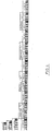
Fig. 4 zeigt ein besonderes Ausführungsbeispiel für eine binäre Codierung, die mit zwei Codezeichen "0" und "1" und einem Trennzeichen "T" arbeitet. Wie dargestellt, besteht das Codezeichen "0" aus der Folge "h-h-d-d-h-h-d-d-h-h-d-d-h-d-d-d". Diese Codeelemente "h" und "d" besitzen die gleiche physikalische Länge auf der Kolbenstange. Alternativ zu der Verwendung von doppelten Codeelementen können auch Codeelemente unterschiedlicher Länge vorgesehen sein, so dass nicht zwei Codeelemente d und h vorgesehen sind, sondern vier Codeelemente mit d, h, dd, hh. Das Codezeichen "1" unterscheidet sich von dem Codezeichen "0" dadurch, dass noch einmal ein schwarz- und weiß-Übergang eingeführt ist. Das Trennzeichen ist durch einen weiteren schwarz-weiß-Übergang dargestellt. - In der in
Fig. 4 dargestellten Codierung liegt nun eine 2-Bit-Codierung vor. Hier wird codiert
T00T11T01T10T. - Die Codewörter "00" und "11" sind hierbei durch ein Trennzeichen "T" voneinander getrennt. Die Codewörter "00" und "11" bilden ein Codewörterpaar mit einer vorgegebenen Gesamtlänge. Ebenso ergibt das Codewort "01" und "10" ein Codewörterpaar mit der gleichen physikalischen Gesamtlänge auf der Kolbenstange.
- Zum besseren Verständnis der Erfindung sei zunächst eine Markierung 5 betrachtet, die keine Codewörterpaare kennt. Nimmt man beispielsweise eine Codierung an, bei der ein Codewort aus drei Bit Länge besteht, so kann folgende Markierung auf der Kolbenstange aufgebracht sein:
000T001T010T011T100T101T110T111, wobei das Trennzeichen zwischen zwei Codewörtern hier durch "T" dargestellt ist. Liest bei dieser Markierung der optische Sensor beispielsweise die Markierung 100T, so war es bekannt, dass der Sensor sich gerade zwischen der fünften und sechsten Markierung befindet, so dass eine Auswertung die Position der Kolbenstange ergibt. In diesem Beispiel haben sämtliche Codewörter die gleiche logische Länge, da sie stets 3 Bit besitzen. Jedoch ist es bei dem Aufbau aus Codeelementen so, dass das Codezeichen "0" beispielsweise als Strich-Lücke-Strich-Strich also d-h-d-d codiert ist, während das Codezeichen "1" eine Darstellung in Codeelementen eine andere physikalische Länge auf der Kolbenstange besitzt. Geht man von einer solchen Situation aus, so besitzen die Codezeichen "0" und "1" nicht die gleiche physikalische Länge, ebenso wenig wie das Codewort "100" und "011" die gleiche physikalische Länge besitzen. - Erfindungsgemäß ist daher vorgesehen, in der Markierung 5 mehrere Codewörterpaare vorzusehen, die die gleiche Länge besitzen. Ein Beispiel ist:
000T111T001T110T010T101T011T100. - Betrachtet man die vorstehende Markierung 5, so stellt man fest, dass die aufeinanderfolgenden Codewörter "000T" und "111T" in einem Paar zusammengefasst, die gleiche Länge besitzen wie die folgenden Paare:
- P1 = ((000T), (111T))
- P2 = ((001T), (110T))
- P3 = ((010T), (101T))
- P4 = ((011T), (100T)).
- Die vier Codewörterpaare P1 - P4 besitzen jeweils die gleiche physikalische Länge auf der Kolbenstange, da sie stets die gleiche Anzahl von Codezeichen "0" und "1" aufweisen. Das Summencodewort ergibt immer (111), denn (010) + (101) = (111). Ein weiterer Vorzug der vorstehenden Codewörterpaare liegt darin, dass innerhalb eines Codewörterpaares die Hamming-Distanz zwischen zwei Codewörtern "3" beträgt, wobei das Trennzeichen "T" außeracht gelassen wird. Eine weitere Eigenschaft besteht darin, dass das letzte Codewort eines Codewörterpaares und das erste Codewort eines nachfolgenden Codewörterpaares einen Abstand von "2" besitzen. Je nach der erforderlichen Länge und Genauigkeit der Aufteilung der Kolbenstange kann eine unterschiedlich große Anzahl von Codezeichen für die Darstellung eines Codewortes gewählt werden.
- Da die Markierung 5 bei der Verwendung der Codewörterpaare nicht sequenziell erfolgt, ist zur Auswertung der Position der Kolbenstange eine Tabelle vorgesehen, die einem einzelnen Codewort eine Position zuordnet.
-
Figur 5 betrifft eine ternäre Codierung mit den Codezeichen "0", "1" und "2" und einem Trennzeichen "T". Das Codezeichen "0" ist hier aus als d-h-d-h-h auf die Kolbenstange aufgetragen. Bei einer Länge von 2 mm für einen hellen und einen dunklen Streifen ergibt sich eine physikalische Gesamtlänge von 10 mm auf der Kolbenstange. Das Codezeichen "1" ist aus den Codeelementen d-h-d-h-d-h-h codiert und besitzt dementsprechend eine Länge von 14 mm auf der Kolbenstange. Das Codezeichen "2" ist aus den Codeelementen d-h-d-h-d-h-d-h-h mit einer physikalischen Länge von 18 mm zusammengesetzt. Das Codezeichen "T" enthält eine zusätzliche Folge d-h gegenüber der "2" und bildet damit die Codezeichenfolge: d-h-d-h-d-h-d-h-d-h-h. Die physikalische Länge auf der Kolbenstange beträgt somit dann 22 mm. - Die Bildung von Codewörtern und Codewörterpaaren erfolgt bei einer ternären also einer 3-adischen Darstellung analog zu der binären Darstellung. Beispielsweise haben vier Codewörterpaare:
- P1= ((0122T),(2100T))
- P2= ((0202T),(2020T))
- P3= ((1222T),(1000T))
- P4= ((0120T),(2102T)).
- Bei der ternären Codierung ist das Codewort, das nur aus "1" auszuschließen, da es hierzu kein korrespondierendes Codewort gibt, um ein Codewörterpaar zu bilden.
- Ein besonderer Vorteil der Codierung mit gleichlangen Codewörterpaaren liegt darin, dass bei der Herstellung einer oder mehrerer Kolbenstangen eine einzige durchgehende Markierung auf eine noch nicht geteilte oder gekürzte Kolbenstange aufgebracht werden kann und die dann ohne Rücksicht auf die Lage der Markierung geteilt und/oder gekürzt werden kann, um in einer konkreten Einbauumgebung verwendet zu werden. Die durchgehende Markierung enthält hierbei keine Wiederholungen der Codewörterpaare und ist insofern eindeutig. Insbesondere bei einer ternären Codierung kommt dieser Vorteil zum Tragen.
-
- 1
- Zylinder
- 2
- Zylinderhülse
- 3
- Kolbenstange
- 4
- Zylinderkopf
- 5
- Markierung
- 6
- Abdeckung
- 7
- Kabel
Claims (13)
- Zylinder (1) mit einer Kolbenstange (3) und einem optischen Positionsmesser, der auf eine an der Kolbenstange (3) angeordnete Markierung (5) gerichtet ist, die eine Anzahl von Codewörtern aufweist, wobei jedes Codewort aus zwei oder mehr Codezeichen und einem Trennzeichen besteht und jedes der zwei oder mehr Code- und Trennzeichen aus einer Abfolge von Codeelementen (h, d) bestehen, die aus einer Menge von mindestens zwei von dem Positionssensor lesbaren und auf die Kolbenstange aufgebrachten Codeelementen (h, d) ausgewählt sind, dadurch gekennzeichnet, dass- b-verschiedene Codezeichen (0, 1, 2,..., b-1) in einer b-adischen Darstellung aus den Codeelementen (h, d) gebildet sind und- zwei oder mehr der Codezeichen (0, 1, 2,..., b-1) ein Codewort in der b-adischen Darstellung bilden.
- Zylinder nach Anspruch 1, dadurch gekennzeichnet, dass die Markierung (5) eine Vielzahl von Codewörterpaaren aus benachbarten Codewörtern aufweist, die paarweise eine vorbestimmte physikalische Gesamtlänge auf der Kolbenstange aufweisen.
- Zylinder nach Anspruch 1 oder 2, dadurch gekennzeichnet, dass b=2 gesetzt ist und die Codewörter in einer binären Codierung vorliegen.
- Zylinder nach Anspruch 3, dadurch gekennzeichnet, dass die Summe von zwei Codewörtern aus einem Codewörterpaar ein Summencodewort ergibt, das nur Einsen enthält.
- Zylinder nach Anspruch 1 oder 2, dadurch gekennzeichnet, dass b=3 gesetzt ist und die Codewörter in einer ternären Codierung vorliegen.
- Zylinder nach Anspruch 5, dadurch gekennzeichnet, dass die Summe von zwei Codewörtern aus einem Codewörterpaar ein Summencodewort ergibt, das nur Zweien enthält.
- Zylinder (1) nach einem der Ansprüche 1 bis 6, dadurch gekennzeichnet, dass die beiden Codewörter in einem Codewörterpaar zusammen zwei Trennzeichen aufweisen.
- Zylinder (1) nach einem der Ansprüche 1 bis 7, dadurch gekennzeichnet, dass jedes Codewort eine vorbestimmte Anzahl von Codezeichen besitzt.
- Zylinder (1) nach einem der Ansprüche 1 bis 8, dadurch gekennzeichnet, dass zwei durch ein Trennzeichen voneinander getrennte Codewörter, die jeweils n Codezeichen aufweisen, sich um einen maximalen Abstand voneinander unterscheiden.
- Zylinder (1) nach Anspruch 9, dadurch gekennzeichnet, dass die Codewörter eines Codewörterpaares sich in allen ihren Codezeichen voneinander unterscheiden.
- Zylinder (1) nach einem der Ansprüche 1 bis 10, dadurch gekennzeichnet, dass die beiden Codezeichen unterschiedliche Längen aufweisen.
- Zylinder nach einem der Ansprüche 1 bis 11, dadurch gekennzeichnet, dass die Codeelemente (h, d) aus hellen und dunklen Streifen auf der Kolbenstange gebildet sind.
- Zylinder nach einem der Ansprüche 1 bis 12, dadurch gekennzeichnet, dass die Codeelemente (h, d) aus hellen und dunklen Streifen gleicher physikalische Länge auf der Kolbenstange gebildet sind.
Priority Applications (1)
| Application Number | Priority Date | Filing Date | Title |
|---|---|---|---|
| EP19156224.8A EP3693708B1 (de) | 2019-02-08 | 2019-02-08 | Zylinder mit einer kolbenstange und einem optischen positionsmesser |
Applications Claiming Priority (1)
| Application Number | Priority Date | Filing Date | Title |
|---|---|---|---|
| EP19156224.8A EP3693708B1 (de) | 2019-02-08 | 2019-02-08 | Zylinder mit einer kolbenstange und einem optischen positionsmesser |
Publications (2)
| Publication Number | Publication Date |
|---|---|
| EP3693708A1 true EP3693708A1 (de) | 2020-08-12 |
| EP3693708B1 EP3693708B1 (de) | 2024-07-17 |
Family
ID=65365871
Family Applications (1)
| Application Number | Title | Priority Date | Filing Date |
|---|---|---|---|
| EP19156224.8A Active EP3693708B1 (de) | 2019-02-08 | 2019-02-08 | Zylinder mit einer kolbenstange und einem optischen positionsmesser |
Country Status (1)
| Country | Link |
|---|---|
| EP (1) | EP3693708B1 (de) |
Citations (7)
| Publication number | Priority date | Publication date | Assignee | Title |
|---|---|---|---|---|
| DE3634730A1 (de) | 1986-10-11 | 1988-04-21 | Klaus Huegler | Arbeitszylinder, insbesondere pneumatikzylinder fuer komponenten von handlingautomaten |
| WO1995001510A1 (en) | 1993-07-02 | 1995-01-12 | Partek Cargotec Oy | A hydraulic, pneumatic or another similar cylinder |
| DE69307135T2 (de) | 1992-04-07 | 1997-04-24 | Partek Cargotec Oy | Positionsskala und optischer lesesensor zum lesen derselben |
| DE69308034T2 (de) | 1992-06-15 | 1997-08-21 | Bootsman Holding B.V., Hoofddorp | Lageerfassungssystem |
| EP1635073A2 (de) * | 2004-09-08 | 2006-03-15 | J.C. Bamford Excavators Ltd. | Rechenmodul |
| EP1426737B1 (de) | 1998-04-02 | 2010-11-03 | J.C. Bamford Excavators Limited | Positionsbestimmungsvorrichtung für ein bewegliches mechanisches Teil und Markierungsverfahren dafür |
| WO2016174517A1 (en) * | 2015-04-30 | 2016-11-03 | Anatech B.V. | Encoders, encoding methods and systems and devices using them |
-
2019
- 2019-02-08 EP EP19156224.8A patent/EP3693708B1/de active Active
Patent Citations (8)
| Publication number | Priority date | Publication date | Assignee | Title |
|---|---|---|---|---|
| DE3634730A1 (de) | 1986-10-11 | 1988-04-21 | Klaus Huegler | Arbeitszylinder, insbesondere pneumatikzylinder fuer komponenten von handlingautomaten |
| DE69307135T2 (de) | 1992-04-07 | 1997-04-24 | Partek Cargotec Oy | Positionsskala und optischer lesesensor zum lesen derselben |
| DE69308034T2 (de) | 1992-06-15 | 1997-08-21 | Bootsman Holding B.V., Hoofddorp | Lageerfassungssystem |
| WO1995001510A1 (en) | 1993-07-02 | 1995-01-12 | Partek Cargotec Oy | A hydraulic, pneumatic or another similar cylinder |
| DE4397478T1 (de) * | 1993-07-02 | 1996-06-27 | Partek Cargotec Oy | Hydraulischer, pneumatischer oder ähnlicher Zylinder |
| EP1426737B1 (de) | 1998-04-02 | 2010-11-03 | J.C. Bamford Excavators Limited | Positionsbestimmungsvorrichtung für ein bewegliches mechanisches Teil und Markierungsverfahren dafür |
| EP1635073A2 (de) * | 2004-09-08 | 2006-03-15 | J.C. Bamford Excavators Ltd. | Rechenmodul |
| WO2016174517A1 (en) * | 2015-04-30 | 2016-11-03 | Anatech B.V. | Encoders, encoding methods and systems and devices using them |
Also Published As
| Publication number | Publication date |
|---|---|
| EP3693708B1 (de) | 2024-07-17 |
Similar Documents
| Publication | Publication Date | Title |
|---|---|---|
| EP2561319B1 (de) | Positionserfassungsvorrichtung und verfahren zur herstellung einer markierungsanordnung für eine positionserfassungsvorrichtung | |
| DE3688909T2 (de) | Messanordnung mit versetzung. | |
| EP0118673B1 (de) | Messeinrichtung | |
| DE2619494C2 (de) | Vorrichtung zur Bestimmung der Lage eines beweglichen Organs | |
| DE69222072T2 (de) | Messanordnung zur Bestimmung einer absoluten Position eines bewegbaren Elements und Skalenteilungselement zur Verwendung in einer derartigen Messanordnung | |
| EP4242595B1 (de) | Vorrichtung und verfahren zur positions-, längen- oder winkelbestimmung | |
| EP0172323A1 (de) | Messeinrichtung | |
| DE2216013A1 (de) | Verfahren und Gerät zum optischen Lesen eines Binärkodes | |
| EP3070342B1 (de) | Fluidzylinder | |
| DE248542T1 (de) | Elektrooptische maus mit aufloesung zur kompensation optischer verzerrungen. | |
| DE2645460C2 (de) | Verfahren und Vorrichtung zum Auswerten von selbsttaktierend codierten Signalen | |
| DE3490549T1 (de) | Photoelektrisches Verschiebungsermittlungsgerät | |
| DE4309863C1 (de) | Positionsmeßeinrichtung sowie Verfahren zum Ablesen eines binären Codewortes | |
| DE102017118509B4 (de) | Zylinder mit einer Kolbenstange und einem optischen Positionsmesser | |
| DE102017204871A1 (de) | Energiesparendes Positionsbestimmungsverfahren | |
| DE102016103721A1 (de) | Zylinder mit einem optischen Positionssensor | |
| EP3693708B1 (de) | Zylinder mit einer kolbenstange und einem optischen positionsmesser | |
| DE2461380C3 (de) | Lesevorrichtung für codierte Informationen | |
| DD159211A1 (de) | Anordnung zur lagebestimmung eines index gegenueber einer teilung | |
| DE3623449C2 (de) | ||
| DE102023134625B3 (de) | Vorrichtung und verfahren zur positions-, längen- oder winkelbestimmung sowie verfahren zur bildung einer entsprechenden codierung | |
| DE102017218900A1 (de) | Kennzeichnung von Werkzeugen oder Werkstücken | |
| EP1770375B1 (de) | Positionsmesseinrichtung mit zwei Massverkörperungen deren Codespuren sich gegenseitig überlappen | |
| EP2340418B1 (de) | Absolute positionscodierung und positionsmessvorrichtung | |
| EP4375621B1 (de) | Vorrichtung und verfahren zur positions-, längen- oder winkelbestimmung |
Legal Events
| Date | Code | Title | Description |
|---|---|---|---|
| PUAI | Public reference made under article 153(3) epc to a published international application that has entered the european phase |
Free format text: ORIGINAL CODE: 0009012 |
|
| STAA | Information on the status of an ep patent application or granted ep patent |
Free format text: STATUS: THE APPLICATION HAS BEEN PUBLISHED |
|
| AK | Designated contracting states |
Kind code of ref document: A1 Designated state(s): AL AT BE BG CH CY CZ DE DK EE ES FI FR GB GR HR HU IE IS IT LI LT LU LV MC MK MT NL NO PL PT RO RS SE SI SK SM TR |
|
| AX | Request for extension of the european patent |
Extension state: BA ME |
|
| STAA | Information on the status of an ep patent application or granted ep patent |
Free format text: STATUS: REQUEST FOR EXAMINATION WAS MADE |
|
| 17P | Request for examination filed |
Effective date: 20210127 |
|
| RBV | Designated contracting states (corrected) |
Designated state(s): AL AT BE BG CH CY CZ DE DK EE ES FI FR GB GR HR HU IE IS IT LI LT LU LV MC MK MT NL NO PL PT RO RS SE SI SK SM TR |
|
| STAA | Information on the status of an ep patent application or granted ep patent |
Free format text: STATUS: EXAMINATION IS IN PROGRESS |
|
| 17Q | First examination report despatched |
Effective date: 20210514 |
|
| P01 | Opt-out of the competence of the unified patent court (upc) registered |
Effective date: 20230628 |
|
| GRAP | Despatch of communication of intention to grant a patent |
Free format text: ORIGINAL CODE: EPIDOSNIGR1 |
|
| STAA | Information on the status of an ep patent application or granted ep patent |
Free format text: STATUS: GRANT OF PATENT IS INTENDED |
|
| INTG | Intention to grant announced |
Effective date: 20240409 |
|
| GRAS | Grant fee paid |
Free format text: ORIGINAL CODE: EPIDOSNIGR3 |
|
| GRAA | (expected) grant |
Free format text: ORIGINAL CODE: 0009210 |
|
| STAA | Information on the status of an ep patent application or granted ep patent |
Free format text: STATUS: THE PATENT HAS BEEN GRANTED |
|
| AK | Designated contracting states |
Kind code of ref document: B1 Designated state(s): AL AT BE BG CH CY CZ DE DK EE ES FI FR GB GR HR HU IE IS IT LI LT LU LV MC MK MT NL NO PL PT RO RS SE SI SK SM TR |
|
| REG | Reference to a national code |
Ref country code: CH Ref legal event code: EP |
|
| REG | Reference to a national code |
Ref country code: DE Ref legal event code: R096 Ref document number: 502019011666 Country of ref document: DE |
|
| REG | Reference to a national code |
Ref country code: IE Ref legal event code: FG4D Free format text: LANGUAGE OF EP DOCUMENT: GERMAN |
|
| REG | Reference to a national code |
Ref country code: LT Ref legal event code: MG9D |
|
| REG | Reference to a national code |
Ref country code: NL Ref legal event code: MP Effective date: 20240717 |
|
| PG25 | Lapsed in a contracting state [announced via postgrant information from national office to epo] |
Ref country code: PT Free format text: LAPSE BECAUSE OF FAILURE TO SUBMIT A TRANSLATION OF THE DESCRIPTION OR TO PAY THE FEE WITHIN THE PRESCRIBED TIME-LIMIT Effective date: 20241118 |
|
| PG25 | Lapsed in a contracting state [announced via postgrant information from national office to epo] |
Ref country code: NL Free format text: LAPSE BECAUSE OF FAILURE TO SUBMIT A TRANSLATION OF THE DESCRIPTION OR TO PAY THE FEE WITHIN THE PRESCRIBED TIME-LIMIT Effective date: 20240717 |
|
| PG25 | Lapsed in a contracting state [announced via postgrant information from national office to epo] |
Ref country code: PT Free format text: LAPSE BECAUSE OF FAILURE TO SUBMIT A TRANSLATION OF THE DESCRIPTION OR TO PAY THE FEE WITHIN THE PRESCRIBED TIME-LIMIT Effective date: 20241118 Ref country code: NL Free format text: LAPSE BECAUSE OF FAILURE TO SUBMIT A TRANSLATION OF THE DESCRIPTION OR TO PAY THE FEE WITHIN THE PRESCRIBED TIME-LIMIT Effective date: 20240717 |
|
| PG25 | Lapsed in a contracting state [announced via postgrant information from national office to epo] |
Ref country code: NO Free format text: LAPSE BECAUSE OF FAILURE TO SUBMIT A TRANSLATION OF THE DESCRIPTION OR TO PAY THE FEE WITHIN THE PRESCRIBED TIME-LIMIT Effective date: 20241017 |
|
| PG25 | Lapsed in a contracting state [announced via postgrant information from national office to epo] |
Ref country code: GR Free format text: LAPSE BECAUSE OF FAILURE TO SUBMIT A TRANSLATION OF THE DESCRIPTION OR TO PAY THE FEE WITHIN THE PRESCRIBED TIME-LIMIT Effective date: 20241018 Ref country code: FI Free format text: LAPSE BECAUSE OF FAILURE TO SUBMIT A TRANSLATION OF THE DESCRIPTION OR TO PAY THE FEE WITHIN THE PRESCRIBED TIME-LIMIT Effective date: 20240717 Ref country code: PL Free format text: LAPSE BECAUSE OF FAILURE TO SUBMIT A TRANSLATION OF THE DESCRIPTION OR TO PAY THE FEE WITHIN THE PRESCRIBED TIME-LIMIT Effective date: 20240717 |
|
| PG25 | Lapsed in a contracting state [announced via postgrant information from national office to epo] |
Ref country code: BG Free format text: LAPSE BECAUSE OF FAILURE TO SUBMIT A TRANSLATION OF THE DESCRIPTION OR TO PAY THE FEE WITHIN THE PRESCRIBED TIME-LIMIT Effective date: 20240717 |
|
| PG25 | Lapsed in a contracting state [announced via postgrant information from national office to epo] |
Ref country code: LV Free format text: LAPSE BECAUSE OF FAILURE TO SUBMIT A TRANSLATION OF THE DESCRIPTION OR TO PAY THE FEE WITHIN THE PRESCRIBED TIME-LIMIT Effective date: 20240717 |
|
| PG25 | Lapsed in a contracting state [announced via postgrant information from national office to epo] |
Ref country code: IS Free format text: LAPSE BECAUSE OF FAILURE TO SUBMIT A TRANSLATION OF THE DESCRIPTION OR TO PAY THE FEE WITHIN THE PRESCRIBED TIME-LIMIT Effective date: 20241117 |
|
| PG25 | Lapsed in a contracting state [announced via postgrant information from national office to epo] |
Ref country code: HR Free format text: LAPSE BECAUSE OF FAILURE TO SUBMIT A TRANSLATION OF THE DESCRIPTION OR TO PAY THE FEE WITHIN THE PRESCRIBED TIME-LIMIT Effective date: 20240717 |
|
| PG25 | Lapsed in a contracting state [announced via postgrant information from national office to epo] |
Ref country code: ES Free format text: LAPSE BECAUSE OF FAILURE TO SUBMIT A TRANSLATION OF THE DESCRIPTION OR TO PAY THE FEE WITHIN THE PRESCRIBED TIME-LIMIT Effective date: 20240717 Ref country code: RS Free format text: LAPSE BECAUSE OF FAILURE TO SUBMIT A TRANSLATION OF THE DESCRIPTION OR TO PAY THE FEE WITHIN THE PRESCRIBED TIME-LIMIT Effective date: 20241017 |
|
| PG25 | Lapsed in a contracting state [announced via postgrant information from national office to epo] |
Ref country code: RS Free format text: LAPSE BECAUSE OF FAILURE TO SUBMIT A TRANSLATION OF THE DESCRIPTION OR TO PAY THE FEE WITHIN THE PRESCRIBED TIME-LIMIT Effective date: 20241017 Ref country code: PL Free format text: LAPSE BECAUSE OF FAILURE TO SUBMIT A TRANSLATION OF THE DESCRIPTION OR TO PAY THE FEE WITHIN THE PRESCRIBED TIME-LIMIT Effective date: 20240717 Ref country code: NO Free format text: LAPSE BECAUSE OF FAILURE TO SUBMIT A TRANSLATION OF THE DESCRIPTION OR TO PAY THE FEE WITHIN THE PRESCRIBED TIME-LIMIT Effective date: 20241017 Ref country code: LV Free format text: LAPSE BECAUSE OF FAILURE TO SUBMIT A TRANSLATION OF THE DESCRIPTION OR TO PAY THE FEE WITHIN THE PRESCRIBED TIME-LIMIT Effective date: 20240717 Ref country code: IS Free format text: LAPSE BECAUSE OF FAILURE TO SUBMIT A TRANSLATION OF THE DESCRIPTION OR TO PAY THE FEE WITHIN THE PRESCRIBED TIME-LIMIT Effective date: 20241117 Ref country code: HR Free format text: LAPSE BECAUSE OF FAILURE TO SUBMIT A TRANSLATION OF THE DESCRIPTION OR TO PAY THE FEE WITHIN THE PRESCRIBED TIME-LIMIT Effective date: 20240717 Ref country code: GR Free format text: LAPSE BECAUSE OF FAILURE TO SUBMIT A TRANSLATION OF THE DESCRIPTION OR TO PAY THE FEE WITHIN THE PRESCRIBED TIME-LIMIT Effective date: 20241018 Ref country code: FI Free format text: LAPSE BECAUSE OF FAILURE TO SUBMIT A TRANSLATION OF THE DESCRIPTION OR TO PAY THE FEE WITHIN THE PRESCRIBED TIME-LIMIT Effective date: 20240717 Ref country code: ES Free format text: LAPSE BECAUSE OF FAILURE TO SUBMIT A TRANSLATION OF THE DESCRIPTION OR TO PAY THE FEE WITHIN THE PRESCRIBED TIME-LIMIT Effective date: 20240717 Ref country code: BG Free format text: LAPSE BECAUSE OF FAILURE TO SUBMIT A TRANSLATION OF THE DESCRIPTION OR TO PAY THE FEE WITHIN THE PRESCRIBED TIME-LIMIT Effective date: 20240717 |
|
| PG25 | Lapsed in a contracting state [announced via postgrant information from national office to epo] |
Ref country code: SM Free format text: LAPSE BECAUSE OF FAILURE TO SUBMIT A TRANSLATION OF THE DESCRIPTION OR TO PAY THE FEE WITHIN THE PRESCRIBED TIME-LIMIT Effective date: 20240717 Ref country code: DK Free format text: LAPSE BECAUSE OF FAILURE TO SUBMIT A TRANSLATION OF THE DESCRIPTION OR TO PAY THE FEE WITHIN THE PRESCRIBED TIME-LIMIT Effective date: 20240717 Ref country code: RO Free format text: LAPSE BECAUSE OF FAILURE TO SUBMIT A TRANSLATION OF THE DESCRIPTION OR TO PAY THE FEE WITHIN THE PRESCRIBED TIME-LIMIT Effective date: 20240717 |
|
| REG | Reference to a national code |
Ref country code: DE Ref legal event code: R097 Ref document number: 502019011666 Country of ref document: DE |
|
| PG25 | Lapsed in a contracting state [announced via postgrant information from national office to epo] |
Ref country code: EE Free format text: LAPSE BECAUSE OF FAILURE TO SUBMIT A TRANSLATION OF THE DESCRIPTION OR TO PAY THE FEE WITHIN THE PRESCRIBED TIME-LIMIT Effective date: 20240717 |
|
| PG25 | Lapsed in a contracting state [announced via postgrant information from national office to epo] |
Ref country code: CZ Free format text: LAPSE BECAUSE OF FAILURE TO SUBMIT A TRANSLATION OF THE DESCRIPTION OR TO PAY THE FEE WITHIN THE PRESCRIBED TIME-LIMIT Effective date: 20240717 |
|
| PG25 | Lapsed in a contracting state [announced via postgrant information from national office to epo] |
Ref country code: SK Free format text: LAPSE BECAUSE OF FAILURE TO SUBMIT A TRANSLATION OF THE DESCRIPTION OR TO PAY THE FEE WITHIN THE PRESCRIBED TIME-LIMIT Effective date: 20240717 |
|
| PLBE | No opposition filed within time limit |
Free format text: ORIGINAL CODE: 0009261 |
|
| STAA | Information on the status of an ep patent application or granted ep patent |
Free format text: STATUS: NO OPPOSITION FILED WITHIN TIME LIMIT |
|
| 26N | No opposition filed |
Effective date: 20250422 |
|
| PG25 | Lapsed in a contracting state [announced via postgrant information from national office to epo] |
Ref country code: SE Free format text: LAPSE BECAUSE OF FAILURE TO SUBMIT A TRANSLATION OF THE DESCRIPTION OR TO PAY THE FEE WITHIN THE PRESCRIBED TIME-LIMIT Effective date: 20240717 |
|
| PG25 | Lapsed in a contracting state [announced via postgrant information from national office to epo] |
Ref country code: MC Free format text: LAPSE BECAUSE OF FAILURE TO SUBMIT A TRANSLATION OF THE DESCRIPTION OR TO PAY THE FEE WITHIN THE PRESCRIBED TIME-LIMIT Effective date: 20240717 |
|
| REG | Reference to a national code |
Ref country code: CH Ref legal event code: PL |
|
| PG25 | Lapsed in a contracting state [announced via postgrant information from national office to epo] |
Ref country code: LU Free format text: LAPSE BECAUSE OF NON-PAYMENT OF DUE FEES Effective date: 20250208 |
|
| PG25 | Lapsed in a contracting state [announced via postgrant information from national office to epo] |
Ref country code: CH Free format text: LAPSE BECAUSE OF NON-PAYMENT OF DUE FEES Effective date: 20250228 |
|
| GBPC | Gb: european patent ceased through non-payment of renewal fee |
Effective date: 20250208 |
|
| REG | Reference to a national code |
Ref country code: BE Ref legal event code: MM Effective date: 20250228 |
|
| PG25 | Lapsed in a contracting state [announced via postgrant information from national office to epo] |
Ref country code: GB Free format text: LAPSE BECAUSE OF NON-PAYMENT OF DUE FEES Effective date: 20250208 |
|
| PG25 | Lapsed in a contracting state [announced via postgrant information from national office to epo] |
Ref country code: BE Free format text: LAPSE BECAUSE OF NON-PAYMENT OF DUE FEES Effective date: 20250228 |
|
| PG25 | Lapsed in a contracting state [announced via postgrant information from national office to epo] |
Ref country code: IE Free format text: LAPSE BECAUSE OF NON-PAYMENT OF DUE FEES Effective date: 20250208 |
|
| PG25 | Lapsed in a contracting state [announced via postgrant information from national office to epo] |
Ref country code: IT Free format text: LAPSE BECAUSE OF FAILURE TO SUBMIT A TRANSLATION OF THE DESCRIPTION OR TO PAY THE FEE WITHIN THE PRESCRIBED TIME-LIMIT Effective date: 20240717 |
|
| PGFP | Annual fee paid to national office [announced via postgrant information from national office to epo] |
Ref country code: DE Payment date: 20260217 Year of fee payment: 8 |
|
| PG25 | Lapsed in a contracting state [announced via postgrant information from national office to epo] |
Ref country code: AT Free format text: LAPSE BECAUSE OF NON-PAYMENT OF DUE FEES Effective date: 20250208 |
|
| REG | Reference to a national code |
Ref country code: AT Ref legal event code: MM01 Ref document number: 1704536 Country of ref document: AT Kind code of ref document: T Effective date: 20250208 |
|
| PGFP | Annual fee paid to national office [announced via postgrant information from national office to epo] |
Ref country code: FR Payment date: 20260219 Year of fee payment: 8 |
|
| PG25 | Lapsed in a contracting state [announced via postgrant information from national office to epo] |
Ref country code: CY Free format text: LAPSE BECAUSE OF FAILURE TO SUBMIT A TRANSLATION OF THE DESCRIPTION OR TO PAY THE FEE WITHIN THE PRESCRIBED TIME-LIMIT Effective date: 20240717 |
|
| PG25 | Lapsed in a contracting state [announced via postgrant information from national office to epo] |
Ref country code: TR Free format text: LAPSE BECAUSE OF FAILURE TO SUBMIT A TRANSLATION OF THE DESCRIPTION OR TO PAY THE FEE WITHIN THE PRESCRIBED TIME-LIMIT Effective date: 20240717 |
|
| PG25 | Lapsed in a contracting state [announced via postgrant information from national office to epo] |
Ref country code: LT Free format text: LAPSE BECAUSE OF FAILURE TO SUBMIT A TRANSLATION OF THE DESCRIPTION OR TO PAY THE FEE WITHIN THE PRESCRIBED TIME-LIMIT Effective date: 20240717 |