EP3693703B1 - Positionsbestimmungssystem - Google Patents
Positionsbestimmungssystem Download PDFInfo
- Publication number
- EP3693703B1 EP3693703B1 EP20153392.4A EP20153392A EP3693703B1 EP 3693703 B1 EP3693703 B1 EP 3693703B1 EP 20153392 A EP20153392 A EP 20153392A EP 3693703 B1 EP3693703 B1 EP 3693703B1
- Authority
- EP
- European Patent Office
- Prior art keywords
- position determination
- environment
- map
- values
- determination system
- Prior art date
- Legal status (The legal status is an assumption and is not a legal conclusion. Google has not performed a legal analysis and makes no representation as to the accuracy of the status listed.)
- Active
Links
- 230000006870 function Effects 0.000 claims description 45
- 230000007613 environmental effect Effects 0.000 claims description 29
- 230000009466 transformation Effects 0.000 claims description 8
- 238000011161 development Methods 0.000 description 11
- 230000018109 developmental process Effects 0.000 description 11
- 238000003860 storage Methods 0.000 description 11
- 230000004807 localization Effects 0.000 description 4
- 230000008859 change Effects 0.000 description 3
- 238000001514 detection method Methods 0.000 description 3
- 238000005259 measurement Methods 0.000 description 3
- 238000000034 method Methods 0.000 description 3
- 238000004519 manufacturing process Methods 0.000 description 2
- YREOLPGEVLLKMB-UHFFFAOYSA-N 3-methylpyridin-1-ium-2-amine bromide hydrate Chemical compound O.[Br-].Cc1ccc[nH+]c1N YREOLPGEVLLKMB-UHFFFAOYSA-N 0.000 description 1
- 238000013144 data compression Methods 0.000 description 1
- 230000001419 dependent effect Effects 0.000 description 1
- 230000005670 electromagnetic radiation Effects 0.000 description 1
- 238000013507 mapping Methods 0.000 description 1
- 230000007935 neutral effect Effects 0.000 description 1
- 239000002245 particle Substances 0.000 description 1
- 239000011295 pitch Substances 0.000 description 1
- 238000012545 processing Methods 0.000 description 1
- 238000013139 quantization Methods 0.000 description 1
- 238000005096 rolling process Methods 0.000 description 1
- 238000004088 simulation Methods 0.000 description 1
- 230000007704 transition Effects 0.000 description 1
- 238000002604 ultrasonography Methods 0.000 description 1
Images

Classifications
-
- G—PHYSICS
- G01—MEASURING; TESTING
- G01C—MEASURING DISTANCES, LEVELS OR BEARINGS; SURVEYING; NAVIGATION; GYROSCOPIC INSTRUMENTS; PHOTOGRAMMETRY OR VIDEOGRAMMETRY
- G01C21/00—Navigation; Navigational instruments not provided for in groups G01C1/00 - G01C19/00
- G01C21/38—Electronic maps specially adapted for navigation; Updating thereof
- G01C21/3804—Creation or updating of map data
- G01C21/3807—Creation or updating of map data characterised by the type of data
- G01C21/383—Indoor data
-
- G—PHYSICS
- G01—MEASURING; TESTING
- G01S—RADIO DIRECTION-FINDING; RADIO NAVIGATION; DETERMINING DISTANCE OR VELOCITY BY USE OF RADIO WAVES; LOCATING OR PRESENCE-DETECTING BY USE OF THE REFLECTION OR RERADIATION OF RADIO WAVES; ANALOGOUS ARRANGEMENTS USING OTHER WAVES
- G01S17/00—Systems using the reflection or reradiation of electromagnetic waves other than radio waves, e.g. lidar systems
- G01S17/02—Systems using the reflection of electromagnetic waves other than radio waves
- G01S17/06—Systems determining position data of a target
- G01S17/42—Simultaneous measurement of distance and other co-ordinates
-
- G—PHYSICS
- G01—MEASURING; TESTING
- G01C—MEASURING DISTANCES, LEVELS OR BEARINGS; SURVEYING; NAVIGATION; GYROSCOPIC INSTRUMENTS; PHOTOGRAMMETRY OR VIDEOGRAMMETRY
- G01C21/00—Navigation; Navigational instruments not provided for in groups G01C1/00 - G01C19/00
- G01C21/20—Instruments for performing navigational calculations
- G01C21/206—Instruments for performing navigational calculations specially adapted for indoor navigation
-
- G—PHYSICS
- G01—MEASURING; TESTING
- G01C—MEASURING DISTANCES, LEVELS OR BEARINGS; SURVEYING; NAVIGATION; GYROSCOPIC INSTRUMENTS; PHOTOGRAMMETRY OR VIDEOGRAMMETRY
- G01C21/00—Navigation; Navigational instruments not provided for in groups G01C1/00 - G01C19/00
- G01C21/26—Navigation; Navigational instruments not provided for in groups G01C1/00 - G01C19/00 specially adapted for navigation in a road network
- G01C21/28—Navigation; Navigational instruments not provided for in groups G01C1/00 - G01C19/00 specially adapted for navigation in a road network with correlation of data from several navigational instruments
- G01C21/30—Map- or contour-matching
-
- G—PHYSICS
- G01—MEASURING; TESTING
- G01C—MEASURING DISTANCES, LEVELS OR BEARINGS; SURVEYING; NAVIGATION; GYROSCOPIC INSTRUMENTS; PHOTOGRAMMETRY OR VIDEOGRAMMETRY
- G01C21/00—Navigation; Navigational instruments not provided for in groups G01C1/00 - G01C19/00
- G01C21/38—Electronic maps specially adapted for navigation; Updating thereof
- G01C21/3863—Structures of map data
- G01C21/387—Organisation of map data, e.g. version management or database structures
- G01C21/3881—Tile-based structures
-
- G—PHYSICS
- G01—MEASURING; TESTING
- G01S—RADIO DIRECTION-FINDING; RADIO NAVIGATION; DETERMINING DISTANCE OR VELOCITY BY USE OF RADIO WAVES; LOCATING OR PRESENCE-DETECTING BY USE OF THE REFLECTION OR RERADIATION OF RADIO WAVES; ANALOGOUS ARRANGEMENTS USING OTHER WAVES
- G01S17/00—Systems using the reflection or reradiation of electromagnetic waves other than radio waves, e.g. lidar systems
- G01S17/88—Lidar systems specially adapted for specific applications
- G01S17/89—Lidar systems specially adapted for specific applications for mapping or imaging
- G01S17/894—3D imaging with simultaneous measurement of time-of-flight at a 2D array of receiver pixels, e.g. time-of-flight cameras or flash lidar
-
- G—PHYSICS
- G06—COMPUTING; CALCULATING OR COUNTING
- G06V—IMAGE OR VIDEO RECOGNITION OR UNDERSTANDING
- G06V20/00—Scenes; Scene-specific elements
- G06V20/50—Context or environment of the image
- G06V20/56—Context or environment of the image exterior to a vehicle by using sensors mounted on the vehicle
Definitions
- the present invention relates to a position determination system for determining a position of a device that is mobile in an environment, an environmental sensor system for a device that is mobile in an environment, and a mobile device with an environmental sensor system.
- a device that can be moved in an environment can be a vehicle or an airplane, for example.
- Position determination systems for determining a position of such a device are generally designed to determine the position of the device by comparing measured values from an environment sensor of the device with an environment map. Such position determination systems are generally used to automatically control the mobile device through the environment and to carry out position or attitude control based on the determined position of the device.
- the accuracy and speed with which the position of the device can be determined largely determine the accuracy and speed that can be achieved when controlling the device.
- the map of the surroundings should be stored in a storage unit in a storage-efficient manner and at the same time it should be possible to read it out of the storage unit with short access times.
- the position can basically be determined in two dimensions and on the basis of a two-dimensional map of the area.
- two-dimensional maps of the environment can include a grid of map values that completely covers the environment, without the resource requirements required for storing and reading out the map values restricting the speed or accuracy of the position determination.
- a mobile device such as a vehicle
- a two-dimensional positioning system cannot easily be used in environments in which a three-dimensional position change of the device is possible.
- a comparison of the measured values of the environmental sensor obtained after the change in position with the merely two-dimensional map values no longer supplies any plausible results.
- Three-dimensional position changes occur in particular when driving on a ramp or when the device pitches or rolls, for example when driving over bumps in the ground.
- the movements in the individual planes are usually decoupled by moving the vehicle between the planes without determining the position, for example in an elevator.
- the maps of the individual levels used to determine the position can then be exchanged.
- an elevator only allows a lower throughput of vehicles.
- Pitching or rolling movements of a vehicle with a two-dimensional positioning system usually lead to an emergency stop of the vehicle being carried out due to the indeterminable position of the vehicle and operation of the vehicle only being resumed when the movements have subsided and the vehicle is again neutral has assumed position relative to the plane of movement. Such an emergency stop slows the vehicle and causes unwanted wear on the vehicle and the road surface.
- the pamphlet DE 10 2017 005 020 A1 describes a method for determining a position of a vehicle in a vehicle environment, in which a position of the vehicle within a lane of a roadway traveled by the vehicle is determined by means of a comparison between boundary coordinates of the lane and position data of the vehicle.
- the technical article: HELEN OLEYNIKOVA ET AL, "Signed Distance Fields: A Natural Representation for Both Mapping and Planning", RSS 2016 WORKSHOP: GEOMETRY AND BEYOND - REPRESENTATIONS, 1 January 2016 generally describes the use of signed distance fields to represent maps in robotics.
- Vito Cappellini ET AL “Image data compression by the discrete cosine transform", Mathematics and Computers in Simulation, pp. 599 - 608 , North-Holland, 1985 describes the application of the discrete cosine transformation in digital image processing.
- the object of the invention is to specify a position determination system for a mobile device, an environment sensor system for a mobile device, and a mobile device in such a way that a position of the device can be determined as quickly and precisely as possible.
- a position determination system for determining a position of a device that is mobile in an environment comprises a position determination unit and a memory unit.
- a map of the surroundings is stored in the storage unit.
- the position determination unit is set up to receive distance measurement values from an environment sensor of the mobile device and to determine the position of the mobile device by comparing the distance measurement values with the map of the environment.
- the stored environment map comprises at least one block, the block comprising an arrangement of map values representing the environment and the map values representing distance values to an edge of the environment.
- the block of the map of the surroundings is stored in the storage unit as coefficients of a combination, for example a linear combination, of basic functions, with the combination/linear combination of the basic functions approximating the map values of the block.
- the map of the surroundings can be stored in the memory unit in a memory-efficient manner if distance values from the edge of the surroundings are stored as map values and at the same time the map values are stored using the coefficients of the linear combination approximating the map values. This is because, as a rule, significantly fewer coefficients are required to approximate the card values than there are card values in the block.
- the surroundings can be subdivided into spatial elements, in particular into a regular arrangement of spatial elements, and the block can represent such a spatial element.
- the space elements can correspond to surface elements, for example rectangular, in particular square surface elements, and in a three-dimensional environment map, the space elements can correspond to volume elements, for example cuboid, in particular cubic volume elements.
- the map values representing the surroundings can in particular be arranged regularly in the block, for example on a grid, and represent spatial points of the spatial elements of the surroundings arranged regularly, for example in the form of a grid.
- the map values can be stored in particular as function values of a signed distance function ( SDF).
- SDF signed distance function
- the individual map values each indicate the shortest distance from the point in space represented by the map values to the edge of the environment (eg a wall).
- the map values have different signs, depending on whether the spatial points represented by the map values are arranged inside or outside the environment.
- the edge of the environment may comprise one or more self-contained edge sections. For example, such an edge section by an outer border of the area and another such border portion may comprise a surrounding recess located within the border, such as a recess located around a pillar or shelf of a production hall.
- the environment can be formed by a driving area of the vehicle or can include a driving area of the vehicle.
- the driving area can, for example, be a hall, in particular a production hall or warehouse.
- the vehicle may be configured to move three-dimensionally in the environment.
- the environment can include an inclined section that can be driven over by the vehicle, such as a ramp.
- the environment can also include several levels that are arranged one above the other and can be driven on by the vehicle.
- the map of the surroundings can include other blocks of this type.
- the blocks can be arranged next to each other and fill the environment.
- the blocks can in particular be arranged regularly next to one another and each comprise an arrangement, in particular a regular arrangement, of map values of the spatial elements of the environment represented by the blocks.
- the map values of all blocks of the map of the surroundings can be stored in the memory unit.
- the map values of the individual blocks are then stored in each case in that coefficients of that linear combination of the basic functions which approximates the map values of the relevant block are stored for the individual blocks.
- the map values approximated by the linear combination of the basis functions of the block form a multidimensional field of map values, in particular they can form a two-dimensional or a three-dimensional field of map values.
- the basis functions can, for example, be multi-dimensional, in particular two-dimensional or three-dimensional, polynomials, basis functions a multi-dimensional, in particular two-dimensional or three-dimensional, discrete cosine transformation (discrete cosine transformation, DCT) or basis functions of another suitable multi-dimensional, in particular two-dimensional or three-dimensional transformation.
- the linear combinations with which the card values of the individual blocks are approximated can each contain a number of basis functions which corresponds to a total number of the card values of the individual blocks.
- the individual blocks can, for example, comprise map values arranged in the form of a grid, with the blocks each comprising 16 map values in all three spatial directions. In total, the individual blocks then each contain 16 3 card values.
- the map values of the individual blocks can then be approximated by linear combinations of 16 3 basis functions, so that a maximum of 16 3 coefficients of the linear combination are to be stored in the memory unit for each block.
- the memory space required to store the blocks of the map of the surroundings can also be reduced by not storing all the coefficients of the individual linear combinations, but only those coefficients whose amplitude or Energy values each exceed a predetermined threshold. Such coefficients can also be referred to as dominant coefficients of the linear combination. In particular, only a maximum of 3, 9 or 27 coefficients can be stored per block.
- the environmental sensor can be in the form of a distance sensor (eg laser scanner) and can record the distance values, for example using the transit time principle. To detect the distance values, the environmental sensor can emit electromagnetic radiation or ultrasound, for example.
- the environment sensor can also be designed as a camera, in particular as a TOF camera (time-of-flight camera).
- the position determination unit can be designed to determine not only the position of the mobile device but also an orientation of the mobile device in space, ie overall a position of the mobile device, by comparing the measured distance values with the map of the surroundings.
- the position determination unit can be set up to compare the measured distance values with the map of the surroundings using a so-called particle filter (sequential Monte Carlo filter, SMC filter) to determine the position or location of the mobile device.
- particle filter simultaneous Monte Carlo filter
- hypothetical measured values are predicted from hypothetical positions of the device using the stored map values of the environment map and the hypothetical measured values are compared with the measured distance values of the environment sensor.
- the position of the mobile device is then determined from that hypothetical position whose hypothetical measured values best match the actually determined measured distance values.
- Such a localization of the mobile device can also be referred to as Monte Carlo localization (MCL).
- MCL Monte Carlo localization
- the position determination unit can be embodied as a logic unit, for example a microcontroller, FPGA or ASIC, and the memory unit can be embodied as a memory module connected to the logic unit or integrated into the logic unit.
- the position determination unit can in particular include a control program in which logic instructions for determining the position of the mobile device are stored.
- the map of the surroundings comprises a plurality of blocks arranged next to one another and filling the surroundings, with only blocks through which the edge of the surroundings runs being stored in the memory unit.
- the blocks can be stored in the memory unit in an addressable manner using a hash function.
- the hash function maps the spatial coordinates of the blocks to memory addresses of the memory unit. If the blocks represent volume elements of a three-dimensional environment, storing the blocks in the memory unit using the hash function can also be described as so-called voxel hashing.
- the extent of the block is at least twice as large and at most ten times as large, in particular at most or exactly five times as large as a scattering of the measured distance values of the environmental sensor.
- the extent of the blocks is large enough to enable the position of the mobile device to be reliably determined even if the measured distance values vary.
- the measured distance values can scatter around the actual distance value, for example due to electronic noise or due to changing environmental conditions.
- the base functions are formed by base functions of a discrete cosine transformation. If cosine functions are used as base functions, the coefficients of the linear combination used to approximate the map values can be compressed particularly easily. In addition, it can be ensured that the linear combinations of the basis functions of the individual blocks are continuous in the boundaries between the blocks.
- the coefficients are According to the invention, the coefficients of the linear combination are only stored in the storage unit if their amounts exceed predetermined threshold values. As a result, the coefficients of the linear combinations can be stored in the memory unit in a particularly memory-efficient manner and can be read out quickly, and the position of the movable device can be determined particularly quickly and reliably.
- the threshold values can be specified in particular within the framework of a so-called quantization coding. Uniform threshold values can be specified for all coefficients. However, different, individual threshold values can also be specified for the individual coefficients.
- a block of the environment map 16 includes 3 map values, then for example the spatial directions can only exceed the predetermined threshold values by 3 coefficients. In this case, instead of 16 3 coefficients, only nine coefficients are stored in the memory unit for the block.
- the threshold values for the individual coefficients are specified individually. It can thereby be ensured that only those coefficients are stored in the memory unit whose assigned base functions are usually required for approximating the map values. If spatial frequencies are assigned to the individual coefficients of the linear combination, the threshold values for the individual coefficients can be specified in such a way that only coefficients whose frequencies are required for approximating the map values are stored.
- the coefficients are stored in compressed form in the memory unit.
- the storage space required for storing the coefficients is particularly small and the position of the moving device can be determined quickly and reliably.
- These coefficients can in particular be stored in lossless compressed form, for example by means of run-length coding and/or Huffman coding.
- a development of the position determination unit is designed to determine the position of the mobile device based on a gradient of the linear combination of the basic functions.
- the basis functions are designed in such a way that the linear combinations formed from the basis functions are continuous at a boundary between the block and an adjacent block.
- the position of the movable element can be determined, for example as part of a Monte Carlo localization, as that position in which it is most likely that the surroundings sensor will generate measured values that are identical to the measured distance values.
- This most probable position can be determined from the set of all hypothetical positions of the mobile device using the gradient determined from the linear combination of basis functions, for example by means of the so-called gradient method (method of steepest descent).
- the gradient of the linear combination can also be used to reconstruct the environment or elements of the environment, such as the edge of the environment, from the linear combination of the basis functions.
- the hypothetical measured values can be determined, for example, within the framework of a Monte Carlo localization.
- a further development of the position determination unit is designed to determine the position, in particular a location, of the mobile device in a three-dimensional coordinate system of the environment, with the block representing a volume element of the environment with a three-dimensional arrangement of the map values.
- the position of the movable device can be determined in particular in six degrees of freedom, with three degrees of freedom defining the position and three further degrees of freedom defining the orientation of the movable device.
- An environment sensor system for a device that is mobile in an environment is also specified, with an environment sensor and a position determination system for determining a position of the mobile device from measured distance values from the environment sensor.
- the environment sensor system can in particular include the position determination system according to the invention. In this respect, all developments and advantages that are described in connection with the position determination system according to the invention also relate to the environment sensor system.
- the position determination system is integrated into a housing of the environment sensor.
- the position determination system is designed to output the position of the mobile device as an output value from the environment sensor system.
- the position determination system can be implemented in a particularly simple and space-saving manner.
- the position determination system can be implemented in particular in a logic unit of the environment sensor.
- the position determination system can be embodied as an embedded system in the surroundings sensor .
- a mobile device in particular a driverless transport vehicle, with an environment sensor system according to the invention is also specified.
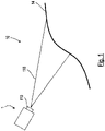
- the mobile device 1 shows a device 1 that can be moved in an area 10.
- the mobile device 1 is designed as a driverless transport vehicle and includes an area sensor 110.
- the area sensor 110 is designed as a laser scanner that works according to the transit time principle and is arranged on a front side of the mobile device 1 in a direction of travel .
- the environment sensor 110 is configured to scan an edge 14 of the environment 10 and to generate measured distance values that represent a distance between the mobile device 1 and the edge 14 of the environment 10 .
- the surroundings sensor 110 is designed to scan the edge 14 of the surroundings 10 in a detection range 115 of the surroundings sensor 110 .
- the detection area 115 can, for example, be arranged in one plane and oriented parallel to a movement plane or driving plane of the mobile device 1 .
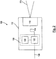
- the environment sensor system 100 includes the environment sensor 110 and a position determination system 120.
- the position determination system 120 includes a position determination unit 122 and a memory unit 124 connected to the position determination unit 122 via a data line.
- the position determination unit 122 is connected to the environment sensor 110 via a data line in order to receive distance measurements 114 generated by environmental sensor 110 .
- the environment sensor 110 and the position determination system 120 are arranged in a common housing 112 of the environment sensor 110 . In this case, the position determination system 120 is implemented in a logic unit of the environmental sensor system 100 .
- the position determination unit 122 is set up to compare the measured distance values 114 of the environment sensor 110 with the environment map 200 to compare, and to determine a position of the mobile device 1 from the comparison.
- the position determination system 120 is also designed to output the position of the mobile device 1 as an output value 126 of the environmental sensor system 100 .
- the output value 126 representing the position of the mobile device 1 is transmitted to a controller of the mobile device 1 and the controller is designed to control, in particular to regulate, the position of the mobile device 1 using the output value 126 .
- the environment map 200 comprises a plurality of (virtual) blocks 210 arranged regularly next to one another.
- the blocks 210 fill in the environment 10, wherein in 3 only a section of the environment map 200 comprising a total of twelve of the blocks 210 is shown.
- the blocks 210 each comprise a regular array of card values 212. In 3 only the card values 212 of the blocks 210 stored in the memory unit 124 are shown. As in 3 is shown, only those blocks 210 through which the edge 14 of the surroundings 10 runs are stored in the memory unit 124 of the position determination system 120 .
- Each of the map values 212 forms a functional value of a signed distance function of the environment 10, the distance function having positive function values in an interior 15 of the environment 10 and negative function values in an exterior 16 of the environment 10.
- the individual blocks 210 are stored in the memory unit 124 in that the memory unit 124 for the individual blocks 210 includes coefficients of linear combinations of basis functions, the linear combinations formed from the coefficients of the individual blocks 210 each approximating the map values 212 of the relevant blocks 210 .
- the basis functions are in each case basis functions of a multi-dimensional, in particular a two-dimensional, discrete cosine transformation.
- the linear combinations of the basic functions formed from the stored coefficients are on Boundaries 222 between the blocks 210, in particular at a boundary 222 between one of the blocks 210 and an adjacent block 220, continuously.
- the blocks 210 can each represent three-dimensional volume elements of the environment 10 and the environment map 200 can be in one 3 analogously also include a three-dimensional arrangement of the blocks 210 .
- the environment map 200 can be above and below the in 3
- the drawing level shown each comprise further levels with map values 212 regularly arranged in a three-dimensional grid.
- the blocks 210 of such an environment map 200 can be stored as coefficients of a linear combination of three-dimensional basis functions.
- the three-dimensional basis functions can, for example, be basis functions of a three-dimensional discrete cosine transformation.
- the coefficients of the individual blocks 210 are each stored in separate storage locations of the storage unit 124, with addresses of the storage locations of the individual blocks 210 being specified in each case by a hash function.
- the hash function maps spatial coordinates of the individual blocks 210 to the memory locations assigned to the blocks 210 in question.
Landscapes
- Engineering & Computer Science (AREA)
- Radar, Positioning & Navigation (AREA)
- Remote Sensing (AREA)
- Physics & Mathematics (AREA)
- General Physics & Mathematics (AREA)
- Automation & Control Theory (AREA)
- Electromagnetism (AREA)
- Computer Networks & Wireless Communication (AREA)
- Multimedia (AREA)
- Theoretical Computer Science (AREA)
- Databases & Information Systems (AREA)
- Control Of Position, Course, Altitude, Or Attitude Of Moving Bodies (AREA)
Description
- Die vorliegende Erfindung betrifft ein Positionsbestimmungssystem zur Bestimmung einer Position eines in einer Umgebung beweglichen Geräts, ein Umgebungssensorsystem für ein in einer Umgebung bewegliches Gerät, sowie ein bewegliches Gerät mit einem Umgebungssensorsystem.
- Ein in einer Umgebung bewegliches Gerät kann beispielsweise ein Fahrzeug oder ein Flugzeug sein. Positionsbestimmungssysteme zur Bestimmung einer Position eines derartigen Geräts sind in der Regel dazu ausgebildet, die Position des Geräts durch einen Vergleich von Messwerten eines Umgebungssensors des Geräts mit einer Umgebungskarte zu ermitteln. Derartige Positionsbestimmungssysteme werden in der Regel dazu verwendet, das bewegliche Gerät automatisiert durch die Umgebung zu steuern und anhand der ermittelten Position des Geräts eine Positions- oder Lageregelung auszuführen. Dabei bestimmen die Genauigkeit und Geschwindigkeit, mit der die Position des Geräts bestimmt werden kann, maßgeblich die bei der Steuerung des Geräts erzielbaren Genauigkeiten und Geschwindigkeiten. Um eine schnelle und sichere Bestimmung der Position des Geräts zu ermöglichen, sollte die Umgebungskarte speichereffizient in einer Speichereinheit hinterlegt und gleichzeitig mit geringen Zugriffszeiten aus der Speichereinheit ausgelesen werden können.
- Ist das Gerät in der Umgebung lediglich in einer Ebene beweglich, handelt es sich bei dem Gerät beispielsweise um ein in einem Stockwerk eines Gebäudes bewegliches Fahrzeug, so kann die Positionsbestimmung grundsätzlich in zwei Dimensionen und auf Grundlage einer zweidimensionalen Umgebungskarte erfolgen. Derartige zweidimensionale Umgebungskarten können in der Regel ein die Umgebung vollständig abdeckendes Gitter von Kartenwerten umfassen, ohne dass der zum Hinterlegen und Auslesen der Kartenwerte benötigte Ressourcenbedarf die Geschwindigkeit oder Genauigkeit der Positionsbestimmung einschränkt.
- Ein bewegliches Gerät, etwa ein Fahrzeug, mit einem zweidimensionalen Positionsbestimmungssystem kann jedoch nicht ohne weiteres in Umgebungen eingesetzt werden, in denen eine dreidimensionale Lageänderung des Geräts möglich ist. Bei einer dreidimensionalen Lageänderung liefert nämlich ein Vergleich der nach der Lageänderung gewonnen Messwerte des Umgebungssensors mit den lediglich zweidimensionalen Kartenwerten keine plausiblen Ergebnisse mehr. Dreidimensionale Lageänderungen erfolgen insbesondere beim Befahren einer Rampe oder bei Nick- oder Wankbewegungen des Geräts, etwa beim Überfahren von Bodenunebenheiten.
- Um ein Fahrzeug mit einem zweidimensionalen Positionsbestimmungssystem dennoch in mehr als einer Ebene automatisiert bewegen zu können, werden die Bewegungen in den einzelnen Ebenen in der Regel dadurch entkoppelt, dass das Fahrzeug ohne Bestimmung der Position zwischen den Ebenen bewegt wird, etwa in einem Aufzug. Während des Übergangs von einer Ebene zur anderen können dann die zur Positionsbestimmung verwendeten Karten der einzelnen Ebenen ausgetauscht werden. Im Vergleich zu einer Rampe ermöglicht jedoch ein Aufzug nur einen geringeren Durchsatz an Fahrzeugen. Nick- oder Wankbewegungen eines Fahrzeugs mit einem zweidimensionalen Positionsbestimmungssystem führen in der Regel dazu, dass aufgrund der unbestimmbaren Lage des Fahrzeugs ein Nothalt des Fahrzeugs ausgeführt wird und der Betrieb des Fahrzeugs erst wieder aufgenommen wird, wenn die Bewegungen abgeklungen sind und das Fahrzeug wieder eine neutrale Lage gegenüber der Bewegungsebene eingenommen hat. Ein derartiger Nothalt verlangsamt das Fahrzeug und führt zu unerwünschtem Verschleiß an Fahrzeug und Fahrfläche.
- Es besteht daher das Bedürfnis, auch lediglich in einer Ebene bewegliche Geräte mit einem dreidimensionalen Positionsbestimmungssystem auszustatten. Eine Hinterlegung dreidimensionaler Kartenwerte ist jedoch aufgrund des dafür benötigten Ressourcenbedarfs oftmals nicht möglich.
- Die Druckschrift
DE 10 2017 005 020 A1 beschreibt ein Verfahren zur Ermittlung einer Position eines Fahrzeugs in einer Fahrzeugumgebung, bei dem eine Position des Fahrzeugs innerhalb einer Fahrspur einer von dem Fahrzeug befahrenen Fahrbahn mittels eines Abgleichs zwischen Begrenzungskoordinaten der Fahrspur und Positionsdaten des Fahrzeugs ermittelt wird. Der Fachartikel: HELEN OLEYNIKOVA ET AL: "Signed Distance Fields: A Natural Representation for Both Mapping and Planning", RSS 2016 WORKSHOP: GEOMETRY AND BEYOND - REPRESENTATIONS, 1. Januar 2016 beschreibt allgemein die Verwendung von signed distance fields zur Darstellung von Karten in der Robotik. Der Fachartikel Vito Cappellini ET AL: "Image data compression by the discrete cosine transform", Mathematics and Computers in Simulation, pp. 599 - 608, North-Holland, 1985 beschreibt die Anwendung der diskreten Cosinustransformation in der digitalen Bildverarbeitung. - Es ist Aufgabe der Erfindung, ein Positionsbestimmungssystem für ein bewegliches Gerät, ein Umgebungssensorsystem für ein bewegliches Gerät, sowie ein bewegliches Gerät derart anzugeben, dass eine Position des Geräts möglichst schnell und genau bestimmt werden kann.
- Diese Aufgabe wird durch ein Positionsbestimmungssystem, ein Umgebungssensorsystem, sowie ein bewegliches Gerät gemäß den unabhängigen Ansprüchen gelöst. Weiterbildungen sind jeweils in den abhängigen Ansprüchen angegeben.
- Ein Positionsbestimmungssystem zur Bestimmung einer Position eines in einer Umgebung beweglichen Geräts umfasst eine Positionsbestimmungseinheit und eine Speichereinheit. In der Speichereinheit ist eine Umgebungskarte der Umgebung hinterlegt. Die Positionsbestimmungseinheit ist dazu eingerichtet, Abstandsmesswerte eines Umgebungssensors des beweglichen Geräts zu empfangen und die Position des beweglichen Geräts durch ein Vergleichen der Abstandsmesswerte mit der Umgebungskarte zu bestimmen. Die hinterlegte Umgebungskarte umfasst mindestens einen Block, wobei der Block eine Anordnung von die Umgebung darstellenden Kartenwerten umfasst und wobei die Kartenwerte Abstandswerte zu einem Rand der Umgebung repräsentieren. Der Block der Umgebungskarte ist in der Speichereinheit als Koeffizienten einer Kombination, beispielsweise einer Linearkombination, von Basisfunktionen hinterlegt, wobei die Kombination/Linearkombination der Basisfunktionen die Kartenwerte des Blocks approximiert.
- Im Rahmen der Erfindung wurde erkannt, dass die Umgebungskarte speichereffizient in der Speichereinheit hinterlegt werden kann, wenn als Kartenwerte Abstandswerte zu dem Rand der Umgebung hinterlegt werden und zugleich die Kartenwerte mittels der Koeffizienten der die Kartenwerte approximierenden Linearkombination hinterlegt werden. Zur Approximation der Kartenwerte werden nämlich in der Regel deutlich weniger Koeffizienten benötigt, als Kartenwerte in dem Block vorhanden sind.
- Zur Erstellung der Umgebungskarte kann die Umgebung in Raumelemente, insbesondere in eine regelmäßige Anordnung von Raumelementen, unterteilt sein und der Block kann ein derartiges Raumelement repräsentieren. Bei einer zweidimensionalen Umgebungskarte können die Raumelemente Flächenelementen, beispielsweise rechteckigen, insbesondere quadratischen Flächenelementen, und bei einer dreidimensionalen Umgebungskarte können die Raumelemente Volumenelementen, beispielsweise quaderförmigen, insbesondere würfelförmigen Volumenelementen, entsprechen. Die die Umgebung darstellenden Kartenwerte können in dem Block insbesondere regelmäßig, etwa auf einem Gitter, angeordnet sein und regelmäßig, etwa gitterförmig, angeordnete Raumpunkte der Raumelemente der Umgebung repräsentieren.
- Die Kartenwerte können insbesondere als Funktionswerte einer vorzeichenbehafteten Abstandsfunktion (signed distance function, SDF) hinterlegt sein. Dabei geben die einzelnen Kartenwerte jeweils den kürzesten Abstand des durch die Kartenwerte jeweils repräsentierten Raumpunkts zu dem Rand der Umgebung (z.B. einer Wand) an. Die Kartenwerte weisen dabei unterschiedliche Vorzeichen auf, je nachdem, ob die durch die Kartenwerte repräsentierten Raumpunkte innerhalb oder außerhalb der Umgebung angeordnet sind. Der Rand der Umgebung kann einen oder mehrere in sich geschlossene Randabschnitte umfassen. Beispielsweise kann ein derartiger Randabschnitt durch eine äußere Umrandung der Umgebung vorgegeben sein und ein weiterer derartiger Randabschnitt kann eine innerhalb der Umrandung angeordnete Aussparung der Umgebung, etwa eine um eine Säule oder ein Regal einer Produktionshalle angeordnete Aussparung, umfassen.
- Ist das bewegliche Gerät als Fahrzeug ausgebildet, kann die Umgebung durch einen Fahrbereich des Fahrzeugs gebildet werden oder einen Fahrbereich des Fahrzeugs umfassen. Der Fahrbereich kann beispielsweise eine Halle, insbesondere eine Produktions- oder Lagerhalle sein. Das Fahrzeug kann dazu ausgebildet sein, sich in der Umgebung dreidimensional zu bewegen. Insbesondere kann die Umgebung einen durch das Fahrzeug befahrbaren geneigten Abschnitt, etwa einer Rampe umfassen. Die Umgebung kann auch mehrere übereinander angeordnete und durch das Fahrzeug befahrbare Ebenen umfassen.
- Neben dem Block kann die Umgebungskarte weitere derartige Blöcke umfassen. Die Blöcke können nebeneinander angeordnet sein und die Umgebung ausfüllen. Die Blöcke können insbesondere regelmäßig nebeneinander angeordnet sein und jeweils eine Anordnung, insbesondere eine regelmäßige Anordnung, von Kartenwerten der durch die Blöcke jeweils repräsentierten Raumelemente der Umgebung umfassen. Dabei können in der Speichereinheit die Kartenwerte aller Blöcke der Umgebungskarte hinterlegt sein. Die Kartenwerte der einzelnen Blöcke sind dann jeweils dadurch hinterlegt, dass für die einzelnen Blöcke jeweils Koeffizienten derjenigen Linearkombination der Basisfunktionen hinterlegt sind, die die Kartenwerte des betreffenden Blocks approximiert.
- Die durch die Linearkombination der Basisfunktionen des Blocks approximierten Kartenwerte bilden ein mehrdimensionales Feld von Kartenwerten, insbesondere können sie ein zweidimensionales oder ein dreidimensionales Feld von Kartenwerten bilden. Die Basisfunktionen können beispielsweise mehrdimensionale, insbesondere zweidimensionale oder dreidimensionale, Polynome, Basisfunktionen einer mehrdimensionalen, insbesondere zweidimensionalen oder dreidimensionalen, diskreten Cosinustransformation (discrete cosine transformation, DCT) oder Basisfunktionen einer anderen geeigneten mehrdimensionalen, insbesondere zweidimensionalen oder dreidimensionalen, Transformation sein.
- Die Linearkombinationen, mit denen die Kartenwerte der einzelnen Blöcke approximiert werden, können jeweils eine Anzahl von Basisfunktionen enthalten, welche eine Gesamtzahl der Kartenwerte der einzelnen Blöcke entspricht. Die einzelnen Blöcke können bei einer dreidimensionalen Umgebungskarte beispielswiese gitterförmig angeordnete Kartenwerte umfassen, wobei die Blöcke in allen drei Raumrichtungen jeweils 16 Kartenwerte umfassen. Insgesamt enthalten die einzelnen Blöcke dann jeweils 163 Kartenwerte. Die Kartenwerte der einzelnen Blöcke können dann durch Linearkombinationen von 163 Basisfunktionen approximiert werden, so dass in der Speichereinheit für jeden Block höchstens 163 Koeffizienten der Linearkombination zu hinterlegen sind. Der Speicherplatz, der zur Hinterlegung der Blöcke der Umgebungskarte benötigt wird, kann jedoch auch dadurch reduziert werden, dass nicht alle Koeffizienten der einzelnen Linearkombinationen hinterlegt werden, sondern lediglich diejenigen Koeffizienten, deren Amplituden-bzw. Energiewerte jeweils einen vorgegebenen Schwellenwert überschreiten. Derartige Koeffizienten können auch als dominante Koeffizienten der Linearkombination bezeichnet werden. Insbesondere können pro Block jeweils nur maximal 3, 9 oder 27 Koeffizienten gespeichert werden.
- Der Umgebungssensor kann als ein Distanzsensor (z.B. Laserscanner) ausgebildet sein und die Abstandswerte beispielsweise mittels des Laufzeitprinzips erfassen. Zum Erfassen der Abstandswerte kann der Umgebungssensor beispielsweise elektromagnetische Strahlung oder Ultraschall aussenden. Der Umgebungssensor kann auch als eine Kamera, insbesondere als eine TOF-Kamera (time-of-flight Kamera) ausgebildet sein.
- Die Positionsbestimmungseinheit kann dazu ausgebildet sein, durch den Vergleich der Abstandsmesswerte mit der Umgebungskarte neben der Position des beweglichen Geräts auch eine Orientierung des beweglichen Geräts im Raum, insgesamt also eine Lage des beweglichen Geräts, zu bestimmen. Die Positionsbestimmungseinheit kann dazu eingerichtet sein, zur Bestimmung der Position bzw. der Lage des beweglichen Geräts die Abstandsmesswerte mit der Umgebungskarte mittels eines sogenannten Partikelfilters (sequenzieller Monte-Carlo-Filter, SMC-Filter) zu vergleichen. Dabei werden aus hypothetischen Lagen des Geräts mittels der hinterlegten Kartenwerte der Umgebungskarte hypothetische Messwerte vorhergesagt und die hypothetischen Messwerte mit den Abstandsmesswerten des Umfeldsensors verglichen. Aus derjenigen hypothetischen Lage, deren hypothetische Messwerte am besten mit den tatsächlich ermittelten Abstandsmesswerten übereinstimmen, wird anschließend die Position des beweglichen Geräts ermittelt. Eine derartige Lokalisierung des beweglichen Geräts kann auch als Monte-Carlo Lokalisierung (MCL) bezeichnet werden.
- Die Positionsbestimmungseinheit kann als eine Logikeinheit, etwa als ein Mikrocontroller, FPGA oder ASIC und die Speichereinheit kann als ein an die Logikeinheit angebundener oder in die Logikeinheit integrierter Speicherbaustein ausgebildet sein. Die Positionsbestimmungseinheit kann insbesondere ein Steuerprogramm umfassen, in welchem Logikanweisungen zur Bestimmung der Position des beweglichen Geräts hinterlegt sind.
- Bei einer Weiterbildung des Positionsbestimmungssystems umfasst die Umgebungskarte eine Mehrzahl nebeneinander angeordneter und die Umgebung ausfüllender Blöcke, wobei in der Speichereinheit nur Blöcke hinterlegt sind, durch die der Rand der Umgebung verläuft. Indem lediglich um den Rand der Umgebung, nicht jedoch in der gesamten Umgebung, angeordnete Blöcke in der Speichereinheit hinterlegt werden, verringert sich der zur Hinterlegung der Umgebungskarte benötigte Speicherbedarf und die Position des beweglichen Geräts kann besonders schnell und sicher bestimmt werden.
- Die Blöcke können in der Speichereinheit mittels einer Hashfunktion adressierbar hinterlegt sein. Die Hashfunktion bildet dabei die räumlichen Koordinaten der Blöcke auf Speicheradressen der Speichereinheit ab. Repräsentieren die Blöcke Volumenelemente einer dreidimensionalen Umgebung, so kann das Hinterlegen der Blöcke in der Speichereinheit mittels der Hashfunktion auch als sogenanntes Voxel-Hashing beschrieben werden.
- Bei einer Weiterbildung des Positionsbestimmungssystems ist eine Ausdehnung des Blocks mindestens doppelt so groß und höchstens zehnmal so groß, insbesondere höchstens oder genau fünfmal so groß, wie eine Streuung der Abstandsmesswerte des Umgebungssensors. Dadurch kann insbesondere dann, wenn lediglich die den Rand der Umgebung umgebenden Blöcke in der Speichereinheit hinterlegt sind, sichergestellt werden, dass die Ausdehnung der Blöcke groß genug ist, um auch bei streuenden Abstandsmesswerten eine zuverlässige Bestimmung der Position des beweglichen Geräts zu ermöglichen. Die Abstandsmesswerte können beispielsweise aufgrund elektronischen Rauschens oder aufgrund sich ändernder Umweltbedingungen um den eigentlichen Abstandswert streuen.
- Bei einer Weiterbildung des Positionsbestimmungssystems werden die Basisfunktionen durch Basisfunktionen einer diskreten Cosinustransformation gebildet. Werden als Basisfunktionen Cosinusfunktionen verwendet, so lassen sich die Koeffizienten der zur Approximation der Kartenwerte verwendeten Linearkombination besonders leicht komprimieren. Außerdem kann sichergestellt werden, dass die Linearkombinationen der Basisfunktionen der einzelnen Blöcke jeweils in den Grenzen zwischen den Blöcken stetig sind.
- Bei einer Weiterbildung des Positionsbestimmungssystems sind die Koeffizienten Erfindungsgemäß sind die Koeffizienten der Linearkombination in der Speichereinheit nur dann hinterlegt, wenn ihre Beträge vorgegebene Schwellenwerte überschreiten. Dadurch können die Koeffizienten der Linearkombinationen besonders speichereffizient und schnell auslesbar in der Speichereinheit hinterlegt werden und die Position des beweglichen Geräts kann besonders schnell und sicher bestimmt werden. Die Schwellenwerte können insbesondere im Rahmen einer sogenannten Quantisierungskodierung vorgegeben sein. Es können für alle Koeffizienten einheitliche Schwellenwerte vorgegeben sein. Es können aber auch jeweils unterschiedliche, individuelle Schwellenwerte für die einzelnen Koeffizienten vorgegeben sein.
- Umfasst ein Block der Umgebungskarte 163 Kartenwerte, so können beispielsweise die Raumrichtungen jeweils nur 3 Koeffizienten die vorgegebenen Schwellenwerte überschreiten. In diesem Fall sind für den Block anstelle von 163 Koeffizienten lediglich neun Koeffizienten in der Speichereinheit hinterlegt.
- Bei einer Weiterbildung des Positionsbestimmungssystems sind die Schwellenwerte für die einzelnen Koeffizienten individuell vorgegeben. Dadurch kann sichergestellt werden, dass nur diejenigen Koeffizienten in der Speichereinheit hinterlegt werden, deren zugeordnete Basisfunktionen zur Approximation der Kartenwerte üblicherweise benötigt werden. Sind den einzelnen Koeffizienten der Linearkombination räumliche Frequenzen zugeordnet, so können die Schwellenwerte für die einzelnen Koeffizienten derart vorgegeben sein, dass lediglich Koeffizienten hinterlegt werden, deren Frequenzen zur Approximation der Kartenwerte benötigt werden.
- Bei einer Weiterbildung des Positionsbestimmungssystems sind die Koeffizienten in der Speichereinheit komprimiert hinterlegt. Dadurch ist der für die Hinterlegung der Koeffizienten benötigte Speicherplatz besonders gering und die Position beweglichen Geräts kann schnell und sicher bestimmt werden. Diese Koeffizienten können insbesondere verlustfrei komprimiert hinterlegt sein, beispielsweise mittels Lauflängenkodierung und/oder Huffman-Kodierung.
- Eine Weiterbildung der Positionsbestimmungseinheit ist dazu ausgebildet, die Position des beweglichen Geräts basierend auf einem Gradienten der Linearkombination der Basisfunktionen zu bestimmen. Die Basisfunktionen sind dabei derart ausgebildet, dass die aus den Basisfunktionen gebildeten Linearkombinationen an einer Grenze zwischen dem Block und einem benachbarten Block stetig sind.
- Die Position des beweglichen Elements kann, beispielsweise im Rahmen einer Monte-Carlo Lokalisierung, als diejenige Position bestimmt werden, in der es am Wahrscheinlichsten ist, dass der Umfeldsensor Messwerte erzeugt, die mit den gemessenen Abstandswerten identisch sind. Diese wahrscheinlichste Position kann aus der Menge aller hypothetischen Positionen des beweglichen Geräts unter Verwendung des aus der Linearkombination von Basisfunktionen bestimmten Gradienten bestimmt werden, beispielsweise mittels des sogenannten Gradientenverfahrens (Verfahren des steilsten Abstiegs). Der Gradient der Linearkombination kann auch dazu verwendet werden, die Umgebung oder Umgebungselemente der Umgebung, etwa den Rand der Umgebung, aus der Linearkombination der Basisfunktionen zu rekonstruieren. Mittels der rekonstruierten Umgebungselemente können im Rahmen einer Monte-Carlo Lokalisierung beispielsweise die hypothetischen Messwerte bestimmt werden.
- Eine Weiterbildung der Positionsbestimmungseinheit ist dazu ausgebildet, die Position, insbesondere eine Lage, des beweglichen Geräts in einem dreidimensionalen Koordinatensystem der Umgebung zu bestimmen, wobei der Block ein Volumenelement der Umgebung mit einer dreidimensionalen Anordnung der Kartenwerte darstellt. Die Lage des beweglichen Geräts kann insbesondere in sechs Freiheitsgraden bestimmt werden, wobei drei Freiheitsgrade die Position und drei weitere Freiheitsgrade die Orientierung des beweglichen Geräts definieren.
- Es wird ferner ein Umgebungssensorsystem für ein in einer Umgebung bewegliches Gerät angegeben mit einem Umgebungssensor und einem Positionsbestimmungssystem zur Bestimmung einer Position des beweglichen Geräts aus Abstandsmesswerten des Umgebungssensors. Das Umgebungssensorsystem kann insbesondere das erfindungsgemäße Positionsbestimmungssystem umfassen. Insoweit beziehen sich alle Weiterbildungen und Vorteile, die im Zusammenhang mit dem erfindungsgemäßen Positionsbestimmungssystem beschrieben werden, auch auf das Umgebungssensorsystem.
- Bei einer Weiterbildung des Umgebungssensorsystems ist das Positionsbestimmungssystem in ein Gehäuse des Umgebungssensors integriert. Das Positionsbestimmungssystem ist dazu ausgebildet, die Position des beweglichen Geräts als Ausgabewert des Umgebungssensorsystems auszugeben. Dadurch kann das Positionsbestimmungssystem besonders einfach und platzsparend implementiert werden. Das Positionsbestimmungssystem kann insbesondere in einer Logikeinheit des Umgebungssensors implementiert sein. Das Positionsbestimmungssystem kann als ein in den Umgebungssensor eingebettetes System (embedded system) ausgebildet sein.
- Es wird außerdem ein bewegliches Gerät, insbesondere ein fahrerloses Transportfahrzeug, mit einem erfindungsgemäßen Umgebungssensorsystem angegeben.
- Die Erfindung wird nachfolgend anhand von Figuren erläutert. Dabei zeigen in jeweils schematischer Darstellung:
- Fig. 1
- ein in einer Umgebung bewegliches Gerät;
- Fig. 2
- ein Umgebungssensorsystem des beweglichen Geräts; und
- Fig. 3
- eine Karte der Umgebung.
-
Fig. 1 zeigt ein in einer Umgebung 10 bewegliches Gerät 1. Das bewegliche Gerät 1 ist als ein fahrerloses Transportfahrzeug ausgebildet und umfasst einen Umgebungssensor 110. Der Umgebungssensor 110 ist als ein nach dem Laufzeitprinzip arbeitender Laserscanner ausgebildet und in einer Fahrtrichtung an einer Vorderseite des beweglichen Geräts 1 angeordnet. - Der Umgebungssensor 110 ist dazu ausgebildet, einen Rand 14 der Umgebung 10 abzutasten und Abstandsmesswerte, die einen Abstand zwischen dem beweglichen Gerät 1 und dem Rand 14 der Umgebung 10 repräsentieren, zu erzeugen. Der Umgebungssensor 110 ist dazu ausgebildet, den Rand 14 der Umgebung 10 in einem Erfassungsbereich 115 des Umgebungssensors 110 abzutasten. Der Erfassungsbereich 115 kann beispielsweise in einer Ebene angeordnet und parallel zu einer Bewegungsebene bzw. Fahrebene des beweglichen Geräts 1 orientiert sein.
- In
Fig. 2 ist ein Umgebungssensorsystem 100 des beweglichen Geräts 1 dargestellt. Das Umgebungssensorsystem 100 umfasst den Umgebungssensor 110, sowie ein Positionsbestimmungssystem 120. Das Positionsbestimmungssystem 120 umfasst eine Positionsbestimmungseinheit 122, sowie eine mit der Positionsbestimmungseinheit 122 über eine Datenleitung verbundene Speichereinheit 124. Die Positionsbestimmungseinheit 122 ist über eine Datenleitung mit dem Umgebungssensor 110 verbunden, um die durch den Umgebungssensor 110 erzeugten Abstandsmesswerte 114 zu empfangen. Der Umgebungssensor 110 und das Positionsbestimmungssystem 120 sind in einem gemeinsamen Gehäuse 112 des Umgebungssensors 110 angeordnet. Dabei ist das Positionsbestimmungssystem 120 in einer Logikeinheit des Umgebungssensorsystems 100 implementiert. - In der Speichereinheit 124 ist eine in
Fig. 3 dargestellte Umgebungskarte 200 hinterlegt und die Positionsbestimmungseinheit 122 ist dazu eingerichtet, die Abstandsmesswerte 114 des Umgebungssensors 110 mit der Umgebungskarte 200 zu vergleichen, sowie aus dem Vergleich eine Position des beweglichen Geräts 1 zu ermitteln. Das Positionsbestimmungssystem 120 ist ferner dazu ausgebildet, die Position des beweglichen Geräts 1 als einen Ausgabewert 126 des Umgebungssensorsystems 100 auszugeben. Der die Position des beweglichen Geräts 1 repräsentierende Ausgabewert 126 wird an eine Steuerung des beweglichen Geräts 1 übertragen und die Steuerung ist dazu ausgebildet, die Position des beweglichen Geräts 1 mittels des Ausgabewert 126 zu steuern, insbesondere zu regeln. - Wie in
Fig. 3 dargestellt ist, umfasst die Umgebungskarte 200 eine Mehrzahl regelmäßig nebeneinander angeordneter (virtueller) Blöcke 210. Die Blöcke 210 füllen die Umgebung 10 aus, wobei inFig. 3 nur ein insgesamt zwölf der Blöcke 210 umfassender Ausschnitt der Umgebungskarte 200 dargestellt ist. Die Blöcke 210 umfassen jeweils eine regelmäßige Anordnung von Kartenwerten 212. InFig. 3 sind lediglich die Kartenwerte 212 der in der Speichereinheit 124 hinterlegten Blöcke 210 dargestellt. Wie inFig. 3 dargestellt ist, sind in der Speichereinheit 124 des Positionsbestimmungssystems 120 lediglich diejenigen Blöcke 210 hinterlegt, durch die der Rand 14 der Umgebung 10 verläuft. - Jeder der Kartenwerte 212 bildet einen Funktionswert einer vorzeichenbehafteten Abstandsfunktion der Umgebung 10, wobei die Abstandsfunktion in einem Inneren 15 der Umgebung 10 positive Funktionswerte und in einem Äußeren 16 der Umgebung 10 negative Funktionswerte annimmt. Die einzelnen Blöcke 210 sind dadurch in der Speichereinheit 124 hinterlegt, dass die Speichereinheit 124 für die einzelnen Blöcke 210 jeweils Koeffizienten von Linearkombinationen von Basisfunktionen umfasst, wobei die aus den Koeffizienten der einzelnen Blöcke 210 jeweils gebildeten Linearkombinationen jeweils die Kartenwerte 212 der betreffenden Blöcke 210 approximieren. Die Basisfunktionen sind in dem hier erläuterten Beispiel jeweils Basisfunktionen einer mehrdimensionalen, insbesondere einer zweidimensionalen, diskreten Cosinustransformation. Die aus den hinterlegten Koeffizienten gebildeten Linearkombinationen der Basisfunktionen sind jeweils an Grenzen 222 zwischen den Blöcken 210, insbesondere an einer Grenze 222 zwischen einem der Blöcke 210 und einem benachbarten Block 220, stetig.
- Bei alternativen Ausführungsformen des Positionsbestimmungssystems 120 können die Blöcke 210 jeweils dreidimensionale Volumenelemente der Umgebung 10 repräsentieren und die Umgebungskarte 200 kann in einer zu
Fig. 3 analogen Weise auch eine dreidimensionale Anordnung der Blöcke 210 umfassen. Beispielsweise kann die Umgebungskarte 200 über und unter der inFig. 3 dargestellten Zeichenebene jeweils weitere Ebenen mit in einem dreidimensionalen Gitter regelmäßig angeordneten Kartenwerten 212 umfassen. Die Blöcke 210 einer derartigen Umgebungskarte 200 können als Koeffizienten einer Linearkombination von dreidimensionalen Basisfunktionen hinterlegt sein. Die dreidimensionalen Basisfunktionen können beispielsweise Basisfunktionen einer dreidimensionalen diskreten Cosinustransformation sein. - Die Koeffizienten der einzelnen Blöcke 210 sind jeweils an separaten Speicherplätzen der Speichereinheit 124 hinterlegt, wobei Adressen der Speicherplätze der einzelnen Blöcke 210 jeweils durch eine Hashfunktion vorgegeben sind. Die Hashfunktion bildet räumliche Koordinaten der einzelnen Blöcke 210 jeweils auf die den betreffenden Blöcken 210 zugeordneten Speicherplätze ab.
-
- 1
- bewegliches Gerät
- 10
- Umgebung
- 12
- Umgebungselement
- 14
- Rand
- 15
- Inneres
- 16
- Äußeres
- 100
- Umgebungssensorsystem
- 110
- Umgebungssensor
- 112
- Gehäuse
- 114
- Abstandsmesswerte
- 115
- Erfassungsbereich
- 120
- Positionsbestimmungssystem
- 122
- Positionsbestimmungseinheit
- 124
- Speichereinheit
- 126
- Ausgabewert
- 200
- Umgebungskarte
- 210
- Block
- 212
- Kartenwerte
- 216
- Schwellenwerte
- 220
- benachbarter Block
- 222
- Grenze
Claims (11)
- Positionsbestimmungssystem (120) zur Bestimmung einer Position eines in einer Umgebung (10) beweglichen Geräts (1),mit einer Positionsbestimmungseinheit (122) und einer Speichereinheit (124),wobei in der Speichereinheit (124) eine Umgebungskarte (200) der Umgebung (10) hinterlegt ist,wobei die Positionsbestimmungseinheit (122) dazu eingerichtet ist, Abstandsmesswerte (114) eines Umgebungssensors (110) des beweglichen Geräts (1) zu empfangen,wobei die Positionsbestimmungseinheit (122) dazu eingerichtet ist, die Position des beweglichen Geräts (1) durch ein Vergleichen der Abstandsmesswerte (114) mit der Umgebungskarte (200) zu bestimmen,wobei die hinterlegte Umgebungskarte (200) mindestens einen Block (210) umfasst,wobei der Block (210) eine Anordnung von die Umgebung (10) darstellenden Kartenwerten (212) umfasst,wobei die Kartenwerte (212) Abstandswerte zu einem Rand (14) der Umgebung (10) repräsentieren,wobei der Block (210) der Umgebungskarte (10) in der Speichereinheit (124) als Koeffizienten einer Linearkombination von Basisfunktionen hinterlegt ist, wobei die Linearkombination der Basisfunktionen die Kartenwerte (212) des Blocks (210) approximiert, undwobei die Koeffizienten der Linearkombination in der Speichereinheit (124) nur dann hinterlegt sind, wenn ihre Beträge vorgegebene Schwellenwerte (216) überschreiten.
- Positionsbestimmungssystem (120) nach Anspruch 1,wobei die Umgebungskarte (200) eine Mehrzahl nebeneinander angeordneter und die Umgebung (10) ausfüllender Blöcke (210) umfasst,wobei in der Speichereinheit (124) nur Blöcke (210) hinterlegt sind, durch die der Rand (14) der Umgebung (10) verläuft.
- Positionsbestimmungssystem (120) nach einem der vorhergehenden Ansprüche,
wobei eine Ausdehnung des Blocks (210) mindestens doppelt so groß und höchstens zehnmal so groß, insbesondere fünfmal so groß, wie eine Streuung der Abstandsmesswerte (114) des Umgebungssensors (110) ist. - Positionsbestimmungssystem (120) nach einem der vorhergehenden Ansprüche,
wobei die Basisfunktionen durch Basisfunktionen einer diskreten Cosinustransformation gebildet werden. - Positionsbestimmungssystem (120) nach einem der vorhergehenden Ansprüche,
wobei die Schwellenwerte (216) für die einzelnen Koeffizienten individuell vorgegeben sind. - Positionsbestimmungssystem (120) nach einem der vorhergehenden Ansprüche,
wobei die Koeffizienten in der Speichereinheit (124) komprimiert hinterlegt sind. - Positionsbestimmungssystem (120) nach einem der vorhergehenden Ansprüche,wobei die Positionsbestimmungseinheit (122) dazu ausgebildet ist, die Position des beweglichen Geräts (1) basierend auf einem Gradienten der Linearkombination der Basisfunktionen zu bestimmen,wobei die Basisfunktionen derart ausgebildet sind, dass die aus den Basisfunktionen gebildeten Linearkombinationen an einer Grenze zwischen dem Block (210) und einem benachbarten Block (220) stetig sind.
- Positionsbestimmungssystem (120) nach einem der vorhergehenden Ansprüche,wobei die Positionsbestimmungseinheit (122) dazu ausgebildet ist, die Position, insbesondere eine Lage, des beweglichen Geräts (1) in einem dreidimensionalen Koordinatensystem der Umgebung (10) zu bestimmen,wobei der Block (210) ein Volumenelement der Umgebung (10) mit einer dreidimensionalen Anordnung der Kartenwerte (212) darstellt.
- Umgebungssensorsystem (10) für ein in einer Umgebung (10) bewegliches Gerät (1)
mit einem Umgebungssensor (110) und einem Positionsbestimmungssystem (120) zur Bestimmung einer Position des beweglichen Geräts (1) aus Abstandsmesswerten (114) des Umgebungssensors (110) nach einem der vorhergehenden Ansprüche. - Umgebungssensorsystem (100) nach Anspruch 9,wobei das Positionsbestimmungssystem (120) in ein Gehäuse (112) des Umgebungssensors (110) integriert ist,wobei das Positionsbestimmungssystem (120) dazu ausgebildet ist, die Position des beweglichen Geräts (1) als Ausgabewert (126) des Umgebungssensorsystems (100) auszugeben.
- Bewegliches Gerät (1), insbesondere fahrerloses Transportfahrzeug, mit einem Umgebungssensorsystem (100) nach einem der Ansprüche 9 bis 10.
Applications Claiming Priority (1)
| Application Number | Priority Date | Filing Date | Title |
|---|---|---|---|
| DE102019103344.6A DE102019103344B4 (de) | 2019-02-11 | 2019-02-11 | Positionsbestimmungssystem |
Publications (2)
| Publication Number | Publication Date |
|---|---|
| EP3693703A1 EP3693703A1 (de) | 2020-08-12 |
| EP3693703B1 true EP3693703B1 (de) | 2022-09-14 |
Family
ID=69190696
Family Applications (1)
| Application Number | Title | Priority Date | Filing Date |
|---|---|---|---|
| EP20153392.4A Active EP3693703B1 (de) | 2019-02-11 | 2020-01-23 | Positionsbestimmungssystem |
Country Status (3)
| Country | Link |
|---|---|
| US (1) | US11513225B2 (de) |
| EP (1) | EP3693703B1 (de) |
| DE (1) | DE102019103344B4 (de) |
Family Cites Families (6)
| Publication number | Priority date | Publication date | Assignee | Title |
|---|---|---|---|---|
| US6587590B1 (en) * | 1998-02-02 | 2003-07-01 | The Trustees Of The University Of Pennsylvania | Method and system for computing 8×8 DCT/IDCT and a VLSI implementation |
| US10082584B2 (en) * | 2012-06-21 | 2018-09-25 | Microsoft Technology Licensing, Llc | Hybrid device location determination system |
| CN109388150B (zh) * | 2014-09-05 | 2022-04-29 | 深圳市大疆创新科技有限公司 | 多传感器环境地图构建 |
| US11378406B2 (en) * | 2017-03-30 | 2022-07-05 | Pioneer Corporation | Determination device, determination method and program |
| DE102017005020A1 (de) * | 2017-05-26 | 2017-12-14 | Daimler Ag | Verfahren zur Bestimmung einer Position eines Fahrzeugs |
| KR102323394B1 (ko) * | 2018-01-22 | 2021-11-08 | 삼성전자주식회사 | 차량의 주행을 보조하는 장치 및 방법 |
-
2019
- 2019-02-11 DE DE102019103344.6A patent/DE102019103344B4/de active Active
-
2020
- 2020-01-23 EP EP20153392.4A patent/EP3693703B1/de active Active
- 2020-02-07 US US16/784,795 patent/US11513225B2/en active Active
Also Published As
| Publication number | Publication date |
|---|---|
| DE102019103344B4 (de) | 2021-02-18 |
| US11513225B2 (en) | 2022-11-29 |
| DE102019103344A1 (de) | 2020-08-13 |
| US20200256996A1 (en) | 2020-08-13 |
| EP3693703A1 (de) | 2020-08-12 |
Similar Documents
| Publication | Publication Date | Title |
|---|---|---|
| EP2490092B1 (de) | Verfahren zur autarken Lokalisierung eines fahrerlosen, motorisierten Fahrzeugs | |
| DE4408328C2 (de) | Verfahren zum Aufbau einer zellular strukturierten Umgebungskarte von einer selbstbeweglichen mobilen Einheit, welche sich mit Hilfe von auf Wellenreflexion basierenden Sensoren orientiert | |
| DE102019121140A1 (de) | Sensorfusion | |
| EP1987371B1 (de) | Verfahren zur detektion von objekten mit einer schwenkbaren sensoreinrichtung | |
| EP3142913B1 (de) | Umfeldkarte für fahrflächen mit beliebigem höhenverlauf | |
| DE102014205170A1 (de) | Verfahren und Vorrichtung zum Ermitteln einer Trajektorie für ein Fahrzeug | |
| DE102014208009A1 (de) | Erfassen von statischen und dynamischen Objekten | |
| EP3091333A1 (de) | Scanverfahren und vermessungssystem mit scanfunktionalität | |
| DE102014207523A1 (de) | Verfahren zum kalibrieren eines radarsensors und radarsystem | |
| DE102018131639A1 (de) | Lidar-punktwolkenkomprimierung | |
| EP3482622A1 (de) | Verfahren zur automatischen führung eines fahrzeugs entlang eines virtuellen schienensystems | |
| EP3693703B1 (de) | Positionsbestimmungssystem | |
| EP2749982B1 (de) | Bezugsmodellerzeugung und Aktualisierung | |
| DE102013008828A1 (de) | Verfahren zur Erstellung eines Modells eines Umfelds eines Fahrzeugs sowie entsprechend ausgestaltetes Fahrerassistenzsystem | |
| DE102011012689B4 (de) | Verfahren zur Bestimmung der Position eines Objekts in einem Bezugssystem | |
| DE102017114223A1 (de) | Nahfeld-Radareinrichtung, Land-, Luft- oder Wasser-Fahrzeug, Verwendung einer Radareinrichtung, Verfahren zum Betrieb einer Radareinrichtung sowie Computerprogramm | |
| EP0364614B1 (de) | Verfahren zur Erkennung der räumlichen Lage und Orientierung vorher bekannter Körper | |
| DE102016200656A1 (de) | Verfahren zum Auswerten eines Umfeldes eines Fahrzeuges | |
| DE102008057139A1 (de) | Verfahren und Vorrichtung zur rechnergestützten Auswahl von Landmarken aus einer räumlichen Umgebung zur Lokalisation eines mobilen Objekts und entsprechendes Computerprogrammprodukt | |
| DE102004050690A1 (de) | Verfahren, Computer-Programm mit Programm-Code-Mitteln, Computer-Programm-Produkt und Gerät zur Modellierung der Umwelt eines autonomen mobilen Systems | |
| EP3663800B1 (de) | Verfahren zur objekterfassung mit einer 3d-kamera | |
| DE102020134978A1 (de) | Sensorkalibrierung | |
| DE102020208835A1 (de) | Antastvorgänge bei einem Koordinatenmessgerät mit Abstandsermittlung | |
| EP4108390B1 (de) | Verfahren zum sicheren betrieb eines beweglichen maschinenteils | |
| DE102018130745A1 (de) | Verfahren zur Steuerung eines autonomen Fahrzeugs |
Legal Events
| Date | Code | Title | Description |
|---|---|---|---|
| PUAI | Public reference made under article 153(3) epc to a published international application that has entered the european phase |
Free format text: ORIGINAL CODE: 0009012 |
|
| STAA | Information on the status of an ep patent application or granted ep patent |
Free format text: STATUS: THE APPLICATION HAS BEEN PUBLISHED |
|
| AK | Designated contracting states |
Kind code of ref document: A1 Designated state(s): AL AT BE BG CH CY CZ DE DK EE ES FI FR GB GR HR HU IE IS IT LI LT LU LV MC MK MT NL NO PL PT RO RS SE SI SK SM TR |
|
| AX | Request for extension of the european patent |
Extension state: BA ME |
|
| STAA | Information on the status of an ep patent application or granted ep patent |
Free format text: STATUS: REQUEST FOR EXAMINATION WAS MADE |
|
| 17P | Request for examination filed |
Effective date: 20201008 |
|
| RBV | Designated contracting states (corrected) |
Designated state(s): AL AT BE BG CH CY CZ DE DK EE ES FI FR GB GR HR HU IE IS IT LI LT LU LV MC MK MT NL NO PL PT RO RS SE SI SK SM TR |
|
| STAA | Information on the status of an ep patent application or granted ep patent |
Free format text: STATUS: EXAMINATION IS IN PROGRESS |
|
| 17Q | First examination report despatched |
Effective date: 20211011 |
|
| 17Q | First examination report despatched |
Effective date: 20211025 |
|
| GRAP | Despatch of communication of intention to grant a patent |
Free format text: ORIGINAL CODE: EPIDOSNIGR1 |
|
| STAA | Information on the status of an ep patent application or granted ep patent |
Free format text: STATUS: GRANT OF PATENT IS INTENDED |
|
| RIC1 | Information provided on ipc code assigned before grant |
Ipc: G06V 20/56 20220101ALI20220510BHEP Ipc: G06K 9/00 20060101ALI20220510BHEP Ipc: G01C 21/00 20060101ALI20220510BHEP Ipc: G01C 21/20 20060101ALI20220510BHEP Ipc: G01C 21/32 20060101AFI20220510BHEP |
|
| INTG | Intention to grant announced |
Effective date: 20220602 |
|
| GRAS | Grant fee paid |
Free format text: ORIGINAL CODE: EPIDOSNIGR3 |
|
| GRAA | (expected) grant |
Free format text: ORIGINAL CODE: 0009210 |
|
| STAA | Information on the status of an ep patent application or granted ep patent |
Free format text: STATUS: THE PATENT HAS BEEN GRANTED |
|
| AK | Designated contracting states |
Kind code of ref document: B1 Designated state(s): AL AT BE BG CH CY CZ DE DK EE ES FI FR GB GR HR HU IE IS IT LI LT LU LV MC MK MT NL NO PL PT RO RS SE SI SK SM TR |
|
| REG | Reference to a national code |
Ref country code: GB Ref legal event code: FG4D Free format text: NOT ENGLISH |
|
| REG | Reference to a national code |
Ref country code: CH Ref legal event code: EP |
|
| REG | Reference to a national code |
Ref country code: DE Ref legal event code: R096 Ref document number: 502020001678 Country of ref document: DE |
|
| REG | Reference to a national code |
Ref country code: IE Ref legal event code: FG4D Free format text: LANGUAGE OF EP DOCUMENT: GERMAN |
|
| REG | Reference to a national code |
Ref country code: AT Ref legal event code: REF Ref document number: 1518964 Country of ref document: AT Kind code of ref document: T Effective date: 20221015 |
|
| REG | Reference to a national code |
Ref country code: LT Ref legal event code: MG9D |
|
| REG | Reference to a national code |
Ref country code: NL Ref legal event code: MP Effective date: 20220914 |
|
| PG25 | Lapsed in a contracting state [announced via postgrant information from national office to epo] |
Ref country code: SE Free format text: LAPSE BECAUSE OF FAILURE TO SUBMIT A TRANSLATION OF THE DESCRIPTION OR TO PAY THE FEE WITHIN THE PRESCRIBED TIME-LIMIT Effective date: 20220914 Ref country code: RS Free format text: LAPSE BECAUSE OF FAILURE TO SUBMIT A TRANSLATION OF THE DESCRIPTION OR TO PAY THE FEE WITHIN THE PRESCRIBED TIME-LIMIT Effective date: 20220914 Ref country code: NO Free format text: LAPSE BECAUSE OF FAILURE TO SUBMIT A TRANSLATION OF THE DESCRIPTION OR TO PAY THE FEE WITHIN THE PRESCRIBED TIME-LIMIT Effective date: 20221214 Ref country code: LV Free format text: LAPSE BECAUSE OF FAILURE TO SUBMIT A TRANSLATION OF THE DESCRIPTION OR TO PAY THE FEE WITHIN THE PRESCRIBED TIME-LIMIT Effective date: 20220914 Ref country code: LT Free format text: LAPSE BECAUSE OF FAILURE TO SUBMIT A TRANSLATION OF THE DESCRIPTION OR TO PAY THE FEE WITHIN THE PRESCRIBED TIME-LIMIT Effective date: 20220914 Ref country code: FI Free format text: LAPSE BECAUSE OF FAILURE TO SUBMIT A TRANSLATION OF THE DESCRIPTION OR TO PAY THE FEE WITHIN THE PRESCRIBED TIME-LIMIT Effective date: 20220914 |
|
| PG25 | Lapsed in a contracting state [announced via postgrant information from national office to epo] |
Ref country code: HR Free format text: LAPSE BECAUSE OF FAILURE TO SUBMIT A TRANSLATION OF THE DESCRIPTION OR TO PAY THE FEE WITHIN THE PRESCRIBED TIME-LIMIT Effective date: 20220914 Ref country code: GR Free format text: LAPSE BECAUSE OF FAILURE TO SUBMIT A TRANSLATION OF THE DESCRIPTION OR TO PAY THE FEE WITHIN THE PRESCRIBED TIME-LIMIT Effective date: 20221215 |
|
| PG25 | Lapsed in a contracting state [announced via postgrant information from national office to epo] |
Ref country code: SM Free format text: LAPSE BECAUSE OF FAILURE TO SUBMIT A TRANSLATION OF THE DESCRIPTION OR TO PAY THE FEE WITHIN THE PRESCRIBED TIME-LIMIT Effective date: 20220914 Ref country code: RO Free format text: LAPSE BECAUSE OF FAILURE TO SUBMIT A TRANSLATION OF THE DESCRIPTION OR TO PAY THE FEE WITHIN THE PRESCRIBED TIME-LIMIT Effective date: 20220914 Ref country code: PT Free format text: LAPSE BECAUSE OF FAILURE TO SUBMIT A TRANSLATION OF THE DESCRIPTION OR TO PAY THE FEE WITHIN THE PRESCRIBED TIME-LIMIT Effective date: 20230116 Ref country code: ES Free format text: LAPSE BECAUSE OF FAILURE TO SUBMIT A TRANSLATION OF THE DESCRIPTION OR TO PAY THE FEE WITHIN THE PRESCRIBED TIME-LIMIT Effective date: 20220914 Ref country code: CZ Free format text: LAPSE BECAUSE OF FAILURE TO SUBMIT A TRANSLATION OF THE DESCRIPTION OR TO PAY THE FEE WITHIN THE PRESCRIBED TIME-LIMIT Effective date: 20220914 |
|
| PGFP | Annual fee paid to national office [announced via postgrant information from national office to epo] |
Ref country code: FR Payment date: 20230123 Year of fee payment: 4 |
|
| PG25 | Lapsed in a contracting state [announced via postgrant information from national office to epo] |
Ref country code: SK Free format text: LAPSE BECAUSE OF FAILURE TO SUBMIT A TRANSLATION OF THE DESCRIPTION OR TO PAY THE FEE WITHIN THE PRESCRIBED TIME-LIMIT Effective date: 20220914 Ref country code: PL Free format text: LAPSE BECAUSE OF FAILURE TO SUBMIT A TRANSLATION OF THE DESCRIPTION OR TO PAY THE FEE WITHIN THE PRESCRIBED TIME-LIMIT Effective date: 20220914 Ref country code: IS Free format text: LAPSE BECAUSE OF FAILURE TO SUBMIT A TRANSLATION OF THE DESCRIPTION OR TO PAY THE FEE WITHIN THE PRESCRIBED TIME-LIMIT Effective date: 20230114 Ref country code: EE Free format text: LAPSE BECAUSE OF FAILURE TO SUBMIT A TRANSLATION OF THE DESCRIPTION OR TO PAY THE FEE WITHIN THE PRESCRIBED TIME-LIMIT Effective date: 20220914 |
|
| REG | Reference to a national code |
Ref country code: DE Ref legal event code: R097 Ref document number: 502020001678 Country of ref document: DE |
|
| PG25 | Lapsed in a contracting state [announced via postgrant information from national office to epo] |
Ref country code: NL Free format text: LAPSE BECAUSE OF FAILURE TO SUBMIT A TRANSLATION OF THE DESCRIPTION OR TO PAY THE FEE WITHIN THE PRESCRIBED TIME-LIMIT Effective date: 20220914 Ref country code: AL Free format text: LAPSE BECAUSE OF FAILURE TO SUBMIT A TRANSLATION OF THE DESCRIPTION OR TO PAY THE FEE WITHIN THE PRESCRIBED TIME-LIMIT Effective date: 20220914 |
|
| PLBE | No opposition filed within time limit |
Free format text: ORIGINAL CODE: 0009261 |
|
| STAA | Information on the status of an ep patent application or granted ep patent |
Free format text: STATUS: NO OPPOSITION FILED WITHIN TIME LIMIT |
|
| PG25 | Lapsed in a contracting state [announced via postgrant information from national office to epo] |
Ref country code: DK Free format text: LAPSE BECAUSE OF FAILURE TO SUBMIT A TRANSLATION OF THE DESCRIPTION OR TO PAY THE FEE WITHIN THE PRESCRIBED TIME-LIMIT Effective date: 20220914 |
|
| 26N | No opposition filed |
Effective date: 20230615 |
|
| PG25 | Lapsed in a contracting state [announced via postgrant information from national office to epo] |
Ref country code: SI Free format text: LAPSE BECAUSE OF FAILURE TO SUBMIT A TRANSLATION OF THE DESCRIPTION OR TO PAY THE FEE WITHIN THE PRESCRIBED TIME-LIMIT Effective date: 20220914 |
|
| REG | Reference to a national code |
Ref country code: CH Ref legal event code: PL |
|
| PG25 | Lapsed in a contracting state [announced via postgrant information from national office to epo] |
Ref country code: LU Free format text: LAPSE BECAUSE OF NON-PAYMENT OF DUE FEES Effective date: 20230123 |
|
| REG | Reference to a national code |
Ref country code: BE Ref legal event code: MM Effective date: 20230131 |
|
| PG25 | Lapsed in a contracting state [announced via postgrant information from national office to epo] |
Ref country code: LI Free format text: LAPSE BECAUSE OF NON-PAYMENT OF DUE FEES Effective date: 20230131 Ref country code: CH Free format text: LAPSE BECAUSE OF NON-PAYMENT OF DUE FEES Effective date: 20230131 |
|
| PG25 | Lapsed in a contracting state [announced via postgrant information from national office to epo] |
Ref country code: BE Free format text: LAPSE BECAUSE OF NON-PAYMENT OF DUE FEES Effective date: 20230131 |
|
| PG25 | Lapsed in a contracting state [announced via postgrant information from national office to epo] |
Ref country code: IE Free format text: LAPSE BECAUSE OF NON-PAYMENT OF DUE FEES Effective date: 20230123 |
|
| PGFP | Annual fee paid to national office [announced via postgrant information from national office to epo] |
Ref country code: DE Payment date: 20240119 Year of fee payment: 5 Ref country code: GB Payment date: 20240124 Year of fee payment: 5 |