EP3693678A1 - Air conditioner - Google Patents
Air conditioner Download PDFInfo
- Publication number
- EP3693678A1 EP3693678A1 EP17923982.7A EP17923982A EP3693678A1 EP 3693678 A1 EP3693678 A1 EP 3693678A1 EP 17923982 A EP17923982 A EP 17923982A EP 3693678 A1 EP3693678 A1 EP 3693678A1
- Authority
- EP
- European Patent Office
- Prior art keywords
- refrigerant
- refrigerant circuit
- cooling
- cooling member
- flows
- Prior art date
- Legal status (The legal status is an assumption and is not a legal conclusion. Google has not performed a legal analysis and makes no representation as to the accuracy of the status listed.)
- Withdrawn
Links
Images





Classifications
-
- F—MECHANICAL ENGINEERING; LIGHTING; HEATING; WEAPONS; BLASTING
- F25—REFRIGERATION OR COOLING; COMBINED HEATING AND REFRIGERATION SYSTEMS; HEAT PUMP SYSTEMS; MANUFACTURE OR STORAGE OF ICE; LIQUEFACTION SOLIDIFICATION OF GASES
- F25B—REFRIGERATION MACHINES, PLANTS OR SYSTEMS; COMBINED HEATING AND REFRIGERATION SYSTEMS; HEAT PUMP SYSTEMS
- F25B13/00—Compression machines, plants or systems, with reversible cycle
-
- F—MECHANICAL ENGINEERING; LIGHTING; HEATING; WEAPONS; BLASTING
- F24—HEATING; RANGES; VENTILATING
- F24F—AIR-CONDITIONING; AIR-HUMIDIFICATION; VENTILATION; USE OF AIR CURRENTS FOR SCREENING
- F24F1/00—Room units for air-conditioning, e.g. separate or self-contained units or units receiving primary air from a central station
- F24F1/06—Separate outdoor units, e.g. outdoor unit to be linked to a separate room comprising a compressor and a heat exchanger
- F24F1/20—Electric components for separate outdoor units
- F24F1/24—Cooling of electric components
-
- F—MECHANICAL ENGINEERING; LIGHTING; HEATING; WEAPONS; BLASTING
- F25—REFRIGERATION OR COOLING; COMBINED HEATING AND REFRIGERATION SYSTEMS; HEAT PUMP SYSTEMS; MANUFACTURE OR STORAGE OF ICE; LIQUEFACTION SOLIDIFICATION OF GASES
- F25B—REFRIGERATION MACHINES, PLANTS OR SYSTEMS; COMBINED HEATING AND REFRIGERATION SYSTEMS; HEAT PUMP SYSTEMS
- F25B1/00—Compression machines, plants or systems with non-reversible cycle
-
- F—MECHANICAL ENGINEERING; LIGHTING; HEATING; WEAPONS; BLASTING
- F25—REFRIGERATION OR COOLING; COMBINED HEATING AND REFRIGERATION SYSTEMS; HEAT PUMP SYSTEMS; MANUFACTURE OR STORAGE OF ICE; LIQUEFACTION SOLIDIFICATION OF GASES
- F25B—REFRIGERATION MACHINES, PLANTS OR SYSTEMS; COMBINED HEATING AND REFRIGERATION SYSTEMS; HEAT PUMP SYSTEMS
- F25B31/00—Compressor arrangements
- F25B31/006—Cooling of compressor or motor
-
- F—MECHANICAL ENGINEERING; LIGHTING; HEATING; WEAPONS; BLASTING
- F25—REFRIGERATION OR COOLING; COMBINED HEATING AND REFRIGERATION SYSTEMS; HEAT PUMP SYSTEMS; MANUFACTURE OR STORAGE OF ICE; LIQUEFACTION SOLIDIFICATION OF GASES
- F25B—REFRIGERATION MACHINES, PLANTS OR SYSTEMS; COMBINED HEATING AND REFRIGERATION SYSTEMS; HEAT PUMP SYSTEMS
- F25B41/00—Fluid-circulation arrangements
-
- F—MECHANICAL ENGINEERING; LIGHTING; HEATING; WEAPONS; BLASTING
- F25—REFRIGERATION OR COOLING; COMBINED HEATING AND REFRIGERATION SYSTEMS; HEAT PUMP SYSTEMS; MANUFACTURE OR STORAGE OF ICE; LIQUEFACTION SOLIDIFICATION OF GASES
- F25B—REFRIGERATION MACHINES, PLANTS OR SYSTEMS; COMBINED HEATING AND REFRIGERATION SYSTEMS; HEAT PUMP SYSTEMS
- F25B41/00—Fluid-circulation arrangements
- F25B41/30—Expansion means; Dispositions thereof
- F25B41/31—Expansion valves
-
- F—MECHANICAL ENGINEERING; LIGHTING; HEATING; WEAPONS; BLASTING
- F25—REFRIGERATION OR COOLING; COMBINED HEATING AND REFRIGERATION SYSTEMS; HEAT PUMP SYSTEMS; MANUFACTURE OR STORAGE OF ICE; LIQUEFACTION SOLIDIFICATION OF GASES
- F25B—REFRIGERATION MACHINES, PLANTS OR SYSTEMS; COMBINED HEATING AND REFRIGERATION SYSTEMS; HEAT PUMP SYSTEMS
- F25B41/00—Fluid-circulation arrangements
- F25B41/30—Expansion means; Dispositions thereof
- F25B41/31—Expansion valves
- F25B41/34—Expansion valves with the valve member being actuated by electric means, e.g. by piezoelectric actuators
-
- F—MECHANICAL ENGINEERING; LIGHTING; HEATING; WEAPONS; BLASTING
- F25—REFRIGERATION OR COOLING; COMBINED HEATING AND REFRIGERATION SYSTEMS; HEAT PUMP SYSTEMS; MANUFACTURE OR STORAGE OF ICE; LIQUEFACTION SOLIDIFICATION OF GASES
- F25B—REFRIGERATION MACHINES, PLANTS OR SYSTEMS; COMBINED HEATING AND REFRIGERATION SYSTEMS; HEAT PUMP SYSTEMS
- F25B41/00—Fluid-circulation arrangements
- F25B41/30—Expansion means; Dispositions thereof
- F25B41/385—Dispositions with two or more expansion means arranged in parallel on a refrigerant line leading to the same evaporator
-
- F—MECHANICAL ENGINEERING; LIGHTING; HEATING; WEAPONS; BLASTING
- F25—REFRIGERATION OR COOLING; COMBINED HEATING AND REFRIGERATION SYSTEMS; HEAT PUMP SYSTEMS; MANUFACTURE OR STORAGE OF ICE; LIQUEFACTION SOLIDIFICATION OF GASES
- F25B—REFRIGERATION MACHINES, PLANTS OR SYSTEMS; COMBINED HEATING AND REFRIGERATION SYSTEMS; HEAT PUMP SYSTEMS
- F25B41/00—Fluid-circulation arrangements
- F25B41/40—Fluid line arrangements
-
- F—MECHANICAL ENGINEERING; LIGHTING; HEATING; WEAPONS; BLASTING
- F25—REFRIGERATION OR COOLING; COMBINED HEATING AND REFRIGERATION SYSTEMS; HEAT PUMP SYSTEMS; MANUFACTURE OR STORAGE OF ICE; LIQUEFACTION SOLIDIFICATION OF GASES
- F25B—REFRIGERATION MACHINES, PLANTS OR SYSTEMS; COMBINED HEATING AND REFRIGERATION SYSTEMS; HEAT PUMP SYSTEMS
- F25B47/00—Arrangements for preventing or removing deposits or corrosion, not provided for in another subclass
- F25B47/02—Defrosting cycles
- F25B47/022—Defrosting cycles hot gas defrosting
-
- F—MECHANICAL ENGINEERING; LIGHTING; HEATING; WEAPONS; BLASTING
- F25—REFRIGERATION OR COOLING; COMBINED HEATING AND REFRIGERATION SYSTEMS; HEAT PUMP SYSTEMS; MANUFACTURE OR STORAGE OF ICE; LIQUEFACTION SOLIDIFICATION OF GASES
- F25B—REFRIGERATION MACHINES, PLANTS OR SYSTEMS; COMBINED HEATING AND REFRIGERATION SYSTEMS; HEAT PUMP SYSTEMS
- F25B49/00—Arrangement or mounting of control or safety devices
- F25B49/02—Arrangement or mounting of control or safety devices for compression type machines, plants or systems
-
- F—MECHANICAL ENGINEERING; LIGHTING; HEATING; WEAPONS; BLASTING
- F25—REFRIGERATION OR COOLING; COMBINED HEATING AND REFRIGERATION SYSTEMS; HEAT PUMP SYSTEMS; MANUFACTURE OR STORAGE OF ICE; LIQUEFACTION SOLIDIFICATION OF GASES
- F25B—REFRIGERATION MACHINES, PLANTS OR SYSTEMS; COMBINED HEATING AND REFRIGERATION SYSTEMS; HEAT PUMP SYSTEMS
- F25B2313/00—Compression machines, plants or systems with reversible cycle not otherwise provided for
- F25B2313/025—Compression machines, plants or systems with reversible cycle not otherwise provided for using multiple outdoor units
- F25B2313/0252—Compression machines, plants or systems with reversible cycle not otherwise provided for using multiple outdoor units with bypasses
-
- F—MECHANICAL ENGINEERING; LIGHTING; HEATING; WEAPONS; BLASTING
- F25—REFRIGERATION OR COOLING; COMBINED HEATING AND REFRIGERATION SYSTEMS; HEAT PUMP SYSTEMS; MANUFACTURE OR STORAGE OF ICE; LIQUEFACTION SOLIDIFICATION OF GASES
- F25B—REFRIGERATION MACHINES, PLANTS OR SYSTEMS; COMBINED HEATING AND REFRIGERATION SYSTEMS; HEAT PUMP SYSTEMS
- F25B2313/00—Compression machines, plants or systems with reversible cycle not otherwise provided for
- F25B2313/025—Compression machines, plants or systems with reversible cycle not otherwise provided for using multiple outdoor units
- F25B2313/0253—Compression machines, plants or systems with reversible cycle not otherwise provided for using multiple outdoor units in parallel arrangements
-
- F—MECHANICAL ENGINEERING; LIGHTING; HEATING; WEAPONS; BLASTING
- F25—REFRIGERATION OR COOLING; COMBINED HEATING AND REFRIGERATION SYSTEMS; HEAT PUMP SYSTEMS; MANUFACTURE OR STORAGE OF ICE; LIQUEFACTION SOLIDIFICATION OF GASES
- F25B—REFRIGERATION MACHINES, PLANTS OR SYSTEMS; COMBINED HEATING AND REFRIGERATION SYSTEMS; HEAT PUMP SYSTEMS
- F25B2313/00—Compression machines, plants or systems with reversible cycle not otherwise provided for
- F25B2313/025—Compression machines, plants or systems with reversible cycle not otherwise provided for using multiple outdoor units
- F25B2313/0254—Compression machines, plants or systems with reversible cycle not otherwise provided for using multiple outdoor units in series arrangements
-
- F—MECHANICAL ENGINEERING; LIGHTING; HEATING; WEAPONS; BLASTING
- F25—REFRIGERATION OR COOLING; COMBINED HEATING AND REFRIGERATION SYSTEMS; HEAT PUMP SYSTEMS; MANUFACTURE OR STORAGE OF ICE; LIQUEFACTION SOLIDIFICATION OF GASES
- F25B—REFRIGERATION MACHINES, PLANTS OR SYSTEMS; COMBINED HEATING AND REFRIGERATION SYSTEMS; HEAT PUMP SYSTEMS
- F25B2400/00—Component parts or details not otherwise provided for in this subclass
- F25B2400/07—Details of compressors or related parts
- F25B2400/075—Details of compressors or related parts with parallel compressors
-
- F—MECHANICAL ENGINEERING; LIGHTING; HEATING; WEAPONS; BLASTING
- F25—REFRIGERATION OR COOLING; COMBINED HEATING AND REFRIGERATION SYSTEMS; HEAT PUMP SYSTEMS; MANUFACTURE OR STORAGE OF ICE; LIQUEFACTION SOLIDIFICATION OF GASES
- F25B—REFRIGERATION MACHINES, PLANTS OR SYSTEMS; COMBINED HEATING AND REFRIGERATION SYSTEMS; HEAT PUMP SYSTEMS
- F25B2600/00—Control issues
- F25B2600/25—Control of valves
- F25B2600/2519—On-off valves
-
- Y—GENERAL TAGGING OF NEW TECHNOLOGICAL DEVELOPMENTS; GENERAL TAGGING OF CROSS-SECTIONAL TECHNOLOGIES SPANNING OVER SEVERAL SECTIONS OF THE IPC; TECHNICAL SUBJECTS COVERED BY FORMER USPC CROSS-REFERENCE ART COLLECTIONS [XRACs] AND DIGESTS
- Y02—TECHNOLOGIES OR APPLICATIONS FOR MITIGATION OR ADAPTATION AGAINST CLIMATE CHANGE
- Y02B—CLIMATE CHANGE MITIGATION TECHNOLOGIES RELATED TO BUILDINGS, e.g. HOUSING, HOUSE APPLIANCES OR RELATED END-USER APPLICATIONS
- Y02B30/00—Energy efficient heating, ventilation or air conditioning [HVAC]
- Y02B30/70—Efficient control or regulation technologies, e.g. for control of refrigerant flow, motor or heating
Definitions
- the present invention relates to an air conditioner.
- an electric circuit such as an inverter circuit configured to control the rotation speed of a compressor is mounted for controlling an operation state of the compressor.
- a power element generating high heat due to power control or supply is used for the inverter circuit.
- a section configured to cool the power element is provided to prevent the power element from having a higher temperature than an operable temperature.
- a refrigerant cooling technique for cooling the power element by refrigerant flowing in a refrigerant circuit has been proposed as one example of such a cooling section.
- Patent Document 1 describes that a "main refrigerant circuit (11) including a compressor (32), a heat source side heat exchanger (30), a first expansion valve (34), and a utilization side heat exchanger (20) and configured such that refrigerant flows in the main refrigerant circuit (11)” and a “branched refrigerant circuit (12) configured such that refrigerant branched from the main refrigerant circuit (11) flows in the branched refrigerant circuit (12)” are provided, a “second expansion valve (61, 62) provided at the branched refrigerant circuit (12) and configured to expand refrigerant flowing into a cooling section (53) and a control section (60) configured to control the second expansion valve (61, 62) are further provided,” and therefore, "the cooling capacity of the cooling section (53) can be controlled and the temperature of an electric component (50a to 50d) (see attached Fig. 4 ) can be properly adjusted.”
- Patent Document 2 describes that "multiple compressors (23A, 23B) are provided, a refrigerant adjustment mechanism adjusts the amount of refrigerant supplied to each cooling section (37A, 37B) corresponding to a power substrate (35A, 35B) of each compressor (23A, 23B) according to operation or performance of each compressor (23A, 23B) in a case where the power substrate (35A, 35B) and the cooling section (37A, 37B) are provided for each compressor (23A, 23B),” and therefore, “cooling of the electric components (35A, 35B) by refrigerant flowing in a refrigerant circuit (18) can be more efficiently performed.”
- the surface temperature of the power element or the surrounding temperature thereof reaches lower than the dew-point temperature of surrounding air, and therefore, there is a probability that dew condensation occurs at a surface of the power element or the periphery thereof.
- the present invention has been made in view of the above-described situation, and is intended to provide an air conditioner configured so that occurrence of dew condensation at a heat generator and the periphery thereof can be reduced.
- an air conditioner of a first aspect of the invention includes a main refrigerant circuit including a compressor, a heat source side heat exchanger, a first expansion valve, and a utilization side heat exchanger and configured such that refrigerant flows in the main refrigerant circuit, a sub refrigerant circuit including a cooling member configured such that refrigerant branched from the main refrigerant circuit flows in the cooling member and configured such that refrigerant branched from the main refrigerant circuit flows in the sub refrigerant circuit, and a heat generator to be cooled by the cooling member.
- a pipe in which part of refrigerant discharged from the compressor flows is connected to the cooling member of the sub refrigerant circuit.
- An air conditioner of a second aspect of the invention includes a main refrigerant circuit including a compressor, a heat source side heat exchanger, a first expansion valve, and a utilization side heat exchanger and configured such that refrigerant flows in the main refrigerant circuit, a sub refrigerant circuit including a cooling member configured such that refrigerant branched from the main refrigerant circuit flows in the cooling member and configured such that refrigerant branched from the main refrigerant circuit flows in the sub refrigerant circuit, a heat generator to be cooled by the cooling member, and a pipe in which part of refrigerant discharged from the compressor flows into the cooling member.
- the pipe is connected to the main refrigerant circuit.
- an air conditioner including a cooler configured to cool multiple heat generators by refrigerant flowing in a refrigerant circuit, occurrence of dew condensation at the heat generator corresponding to a stopped one of the multiple heat generators and the periphery thereof can be reduced.
- refrigerant or a refrigerating cycle indicates refrigerant or a refrigerating cycle available for cooling, heating, or both.
- Fig. 1A is a diagram of a refrigerating cycle of an air conditioner 1 according to a first embodiment.
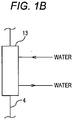
- Fig. 1B is a diagram in a case where a heat source side heat exchanger 13 according to the first embodiment is a heat exchanger configured to exchange heat between water and refrigerant.
- the air conditioner 1 according to the first embodiment as illustrated in Fig. 1A includes a heat source unit 2 (e.g., an outdoor unit) configured to supply heat, and a utilization unit 3 (e.g., an indoor unit) configured to performing cooling/heating by means of such a heat.
- the heat source unit 2 and the utilization unit 3 are connected to each other via refrigerant pipes 1L, 1 V.
- the number of heat source units 2 and the number of utilization units 3 are not limited to one, and multiple heat source units 2 and multiple utilization units 3 may be provided.
- the utilization unit 3 includes a utilization side expansion valve 17 as a depressurization device on a utilization unit 3 side, a utilization side heat exchanger 16, and an air blower 18.
- the air blower 18 is configured to send air into the utilization side heat exchanger 16 to promote heat exchange with air in the utilization side heat exchanger 16.
- the heat source unit 2 has a main refrigerant circuit 4, a branched refrigerant circuit (a sub refrigerant circuit) 5, and a discharged gas branching refrigerant circuit (pipe) 6.
- the main refrigerant circuit 4 is a main circuit for performing, e.g., cooling/heating by the air conditioner 1.
- the branched refrigerant circuit 5 is a circuit in which low-temperature refrigerant flows to cool power elements (heat generators) 31, 32 used for control of the air conditioner 1.
- the discharged gas branching refrigerant circuit 6 is a circuit in which high-temperature refrigerant flows to reduce frosting of the power elements 31, 32.
- the main refrigerant circuit 4 is a circuit connected to main components of the heat source unit 2.
- the main refrigerant circuit 4 includes a first compressor 11, a second compressor 12, a four-way valve 20 functioning to switch a refrigerant flow path direction between cooling operation and heating operation, a gas side closing valve 21, a liquid side closing valve 22, the heat source side heat exchanger 13, and a first expansion valve 15 as a depressurization device on a heat source unit 2 side.
- the heat source unit 2 described herein includes an air blower 14 configured to send air into the heat source side heat exchanger 13 to promote heat exchange in a case where the heat source side heat exchanger 13 is a heat exchanger configured to exchange heat between air and refrigerant flowing in the main refrigerant circuit 4.
- the air blower 14 can be omitted in a case where the heat source side heat exchanger 13 is the heat exchanger configured to exchange heat between water and refrigerant.
- refrigerant discharged from the first and second compressors 11, 12 flows into the heat source side heat exchanger 13 through the four-way valve 20. Such refrigerant releases heat to air or water by heat exchange, and is condensed.
- High-pressure gas refrigerant discharged from the first and second compressors 11, 12 turns into high-pressure liquid refrigerant by heat exchange in the heat source side heat exchanger 13.
- the high-pressure liquid refrigerant is depressurized according to the degree of opening of the first expansion valve 15.
- the refrigerant is less depressurized as the degree of opening of the first expansion valve 15 increases, and is more depressurized as the degree of opening of the first expansion valve 15 decreases.
- the first expansion valve 15 is sometimes in a fully-open state.
- the liquid refrigerant depressurized by the first expansion valve 15 is sent to the utilization unit 3 by way of the liquid side closing valve 22 and the refrigerant pipe 1L.
- the low-pressure liquid refrigerant (or the refrigerant in an air-liquid two-phase state) sent to the utilization unit 3 is further depressurized when passing through the utilization side expansion valve 17, and is sent to the utilization side heat exchanger 16.
- the low-pressure refrigerant sent in the air-liquid two-phase state to the utilization side heat exchanger 16 absorbs heat by heat exchange with indoor air, and cooling is performed. Such refrigerant is evaporated into low-pressure gas refrigerant.
- the low-pressure gas refrigerant is sent to the heat source unit 2 by way of the refrigerant pipe 1V, and is sucked into the first and second compressors 11, 12 by way of the gas side closing valve 21 and the four-way valve 20.
- refrigerant discharged from the first and second compressors 11, 12 is sent to the utilization unit 3 by way of the four-way valve 20, the gas side closing valve 21, and the refrigerant pipe 1V.
- the high-pressure gas refrigerant sent to the utilization unit 3 releases heat by heat exchange with indoor air in the utilization side heat exchanger 16, and heating is performed.
- the utilization side heat exchanger 16 the high-pressure gas refrigerant releases heat, and is condensed into high-pressure liquid refrigerant.
- the utilization side expansion valve 17 is sometimes in a fully-open state.
- the refrigerant having passed through the utilization side expansion valve 17 is sent to the heat source unit 2 by way of the refrigerant pipe 1L.
- the liquid refrigerant sent to the heat source unit 2 is further depressurized according to the degree of opening when passing through the first expansion valve 15 by way of the liquid side closing valve 22, and flows into the heat source side heat exchanger 13.
- the low-pressure refrigerant flowing into the heat source side heat exchanger 13 in an air-liquid two-phase state absorbs heat from external air or water, and is evaporated.
- the low-pressure refrigerant in the air-liquid two-phase state turns into low-pressure gas refrigerant.
- the low-pressure gas refrigerant having flowed out of the heat source side heat exchanger 13 is sucked into the first and second compressors 11, 12 by way of the four-way valve 20.
- the branched refrigerant circuit 5 is a circuit in which refrigerant branched from the main refrigerant circuit 4 flows.
- the branched refrigerant circuit 5 is configured to cool the power elements 31, 32 generating heat.
- the branched refrigerant circuit 5 is provided in parallel with the main refrigerant circuit 4 at a portion from a portion between the heat source side heat exchanger 13 and the first expansion valve 15 of the main refrigerant circuit 4 to a portion between the first expansion valve 15 and the liquid side closing valve 22.
- the branched refrigerant circuit 5 includes a cooling member 41 for the power element 31, a cooling member 42 for the power element 32, and a second expansion valve 43.
- the branched refrigerant circuit 5 is brought into a use state only in the case of cooling the power elements 31, 32.
- the second expansion valve 43 is closed, and the branched refrigerant circuit 5 is brought into a non-use state.
- the cooling member 41 is a member configured to cool the power element 31 of which the temperature is high due to heat generation.
- the cooling member 42 is a member configured to cool the power element 32 of which the temperature is high due to heat generation.
- part of refrigerant flowing in the main refrigerant circuit 4 is branched into the branched refrigerant circuit 5 from the portion between the heat source side heat exchanger 13 and the first expansion valve 15.
- the branched refrigerant flows in the second expansion valve 43, the cooling member 41, and the cooling member 42 in this order, and joins the main refrigerant circuit 4 at the portion between the first expansion valve 15 and the liquid side closing valve 22.
- part of refrigerant flowing in the main refrigerant circuit 4 is branched into the branched refrigerant circuit 5 from the portion between the liquid side closing valve 22 and the first expansion valve 15.
- the branched refrigerant flows, contrary to the cooling operation, in the cooling member 42, the cooling member 41, and the second expansion valve 43 in this order, and joins the main refrigerant circuit 4 at a position between the first expansion valve 15 and the heat source side heat exchanger 13. That is, the flow of refrigerant in the branched refrigerant circuit is reversed between the cooling operation and the heating operation.
- the flow rate of refrigerant flowing in the branched refrigerant circuit 5 may be the same as the flow rate of refrigerant flowing in the main refrigerant circuit 4, but may be lower than the flow rate of refrigerant flowing in the main refrigerant circuit 4.
- the cooling capacities of the cooling members 41, 42 are increased, and therefore, overheating of the power elements 31, 32 can be reduced.
- the cooling capacities of the cooling members 41, 42 are decreased, and therefore, overcooling of the power elements 31, 32 can be prevented.
- dew condensation at the power elements 31, 32 and the periphery thereof can be reduced.
- the power element 31 of the power elements 31, 32 and the cooling member 41 of the cooling members 41, 42 are provided near the second expansion valve 43, but the power element 32 and the cooling member 42 may be provided near the second expansion valve 43.
- the discharged gas branching refrigerant circuit 6 is a circuit configured to heat the power elements 31, 32 to reduce frosting of the power elements 31, 32.
- refrigerant branched from discharge pipes 11t, 12t of the first and second compressors 11, 12 flows.
- the discharged gas branching refrigerant circuit 6 is provided in parallel with the main refrigerant circuit 4 at a portion from a portion between each of the first and second compressors 11, 12 and the four-way valve 20 to a portion between the second expansion valve 43 and the cooling member 41, 42.
- the discharged gas branching refrigerant circuit 6 includes an electromagnetic valve 50 configured to switch the discharged gas branching refrigerant circuit 6 between the use state and the non-use state.
- the electromagnetic valve 50 is closed in a normal state (a steady state), and the discharged gas branching refrigerant circuit 6 is in the non-use state.
- the electromagnetic valve 50 is opened, part of high-pressure high-temperature gas refrigerant discharged from the first and second compressors 11, 12 flows into the discharged gas branching refrigerant circuit 6 from the portion between each of the first and second compressors 11, 12 and the four-way valve 20, and the discharged gas branching refrigerant circuit 6 is brought into the use state.
- Such refrigerant joins the branched refrigerant circuit 5 at the portion between the second expansion valve 43 and the cooling member 41, 42.
- Fig. 2A is a partial front view of an inverter device 30, and Fig. 2B is a partial view of the inverter device 30 from the direction of an arrow A.
- the inverter device 30 is a circuit configured to control the power of the air conditioner 1, and the temperature thereof is increased due to heat generation from the power elements 31, 32 as components.
- the power elements 31, 32 are attached to one side of a printed-circuit board 33 in the inverter device 30.
- the cooling members 41, 42 include refrigerant jackets 43a, 43b made of a metal with high thermal conductivity, such as aluminum or copper, and a refrigerant pipe 44 embedded in each of the refrigerant jackets 43a, 43b.
- Refrigerant branched from the main refrigerant circuit 4 flows in the refrigerant pipe 44 in the branched refrigerant circuit 5 (see Fig. 1A ).
- the cooling members 41, 42 in which refrigerant flows form a cooler.
- the refrigerant jackets 43a, 43b are formed in a slightly-thick flat plate shape to increase a thermal capacity.
- Each of the refrigerant jackets 43a, 43b is attached to one side of a corresponding one of the power elements 31,32.
- each of the refrigerant jackets 43a, 43b closely contacts one surface of a corresponding one of the power elements 31, 32.
- Refrigerant flowing in the refrigerant pipe 44 of the branched refrigerant circuit 5 absorbs heat from the power elements 31, 32 via the refrigerant jackets 43a, 43b.
- the cooling members 41, 42 each include cooling section temperature sensors 71a, 71b.
- the cooling section temperature sensors 71a, 71b are configured to sense the surface temperatures of the refrigerant jackets 43a, 43b.
- each of the cooling section temperature sensors 71a, 71b is attached to one surface 43a1, 43b1 of a corresponding one of the cooling members 41, 42 contacting the power element 31, 32.
- the cooling section temperature sensors 71a, 71b may be each provided in the power elements 31, 32, or may be provided on the surfaces of the power elements 31, 32.
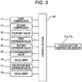
- Fig. 3 is a diagram of a control system of the air conditioner 1.
- a control section 60 is configured to control operation of the air conditioner 1 based on detection signals received from various sensors provided at the air conditioner 1.
- the control section 60 may be provided at the heat source unit 2, or may be provided at the utilization unit 3. Alternatively, the control section 60 may be provided separately at the heat source unit 2 and the utilization unit 3 in terms of functions.
- the control section 60 includes, for example, a not-shown microcomputer.
- the control section 60 controls the first and second compressors 11, 12 (the power elements 31, 32), the four-way valve 20, the first expansion valve 15, the second expansion valve 43, the electromagnetic valve 50, and the air blower 14 mounted on the heat source unit 2, the utilization side expansion valve 17, and the air blower 18.
- Measurement values of the cooling section temperature sensors 71a, 71b each placed at the cooling members 41, 42 are input as control information to the control section 60.
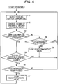
- Fig. 4 is a chart of the control flow of the air conditioner 1 of the first embodiment.
- the control flow of the air conditioner 1 is executed by the microcomputer mounted on the control section 60 (see Fig. 3 ) provided at the heat source unit 2, for example.
- the control section 60 detects, at a step S1, each of the cooling section temperatures of the refrigerant jackets 43a, 43b by the cooling section temperature sensors 71a, 71b ( Fig. 2A ).
- the control section 60 adjusts the degree of opening of the second expansion valve 43 of the branched refrigerant circuit 5 such that each of the cooling section temperatures of the refrigerant jackets 43a, 43b detected at the step S1 reaches a target cooling section temperature. Specifically, in a case where each of the cooling section temperatures of the refrigerant jackets 43a, 43b is higher than the target cooling section temperature, the second expansion valve 43 is opened to promote cooling, and the flow rate of refrigerant flowing in the cooling members 41, 42 is increased.
- the second expansion valve 43 is closed, and the flow rate of refrigerant flowing in the cooling members 41, 42 is decreased. Note that refrigerant flows in the second expansion valve 43, the cooling member 41, and the cooling member 42 in this order in the cooling operation, and flows in the cooling member 42, the cooling member 41, and the second expansion valve 43 in this order in the heating operation.
- the target cooling section temperature described herein may be a fixed temperature.
- the target cooling section temperature may be a variable temperature value according to, e.g., each of the rotation speeds of the first and second compressors 11, 12 or an inverter current value.
- the cooling capacities of the cooling members 41, 42 as the cooler change.
- the target cooling section temperature may be a variable temperature value according to the temperature of refrigerant flowing in the cooling members 41, 42 illustrated in Fig. 2A or the temperature of refrigerant therearound. Note that for reducing occurrence of dew condensation, the target cooling section temperature is set higher than a later-described dew condensation temperature.
- the control section 60 determines whether or not a dew condensation occurrence condition under which it is determined that dew condensation might occur at the power elements 31, 32 or a member therearound is satisfied.
- the control section 60 transitions to a step S4.
- the control section 60 transitions to a step S6.
- Determination on whether or not the dew condensation occurrence condition is satisfied as described herein is made based on whether or not the temperatures of the cooling section temperature sensors 71a, 71b fall below the dew condensation temperature.
- the dew condensation temperature may be a fixed temperature value, or may be a variable temperature value according to the surrounding temperatures of the power elements 31, 32 or the refrigerant jackets 43a, 43b, considering that a dew-point temperature changes according to the surrounding temperatures of the power elements 31, 32 or the refrigerant jackets 43a, 43b.
- the control section 60 determines whether or not the electromagnetic valve 50 is opened. In a case where the electromagnetic valve 50 is not opened (NO at the step S4), the control section 60 returns to the step S1. In a case where the electromagnetic valve 50 is opened (YES at the step S4), the control section 60 transitions to a step S5.
- control section 60 returns to the step S1 after the electromagnetic valve 50 has been closed. That is, the electromagnetic valve is closed.
- the control section 60 determines whether or not the electromagnetic valve 50 is closed. In a case where the electromagnetic valve 50 is not closed (NO at the step S6), the control section 60 returns to the step S1. In a case where the electromagnetic valve 50 is closed (YES at the step S6), the control section 60 transitions to a step S7.
- control section 60 returns to the step S1 after the electromagnetic valve 50 has been opened.
- the power element 31 corresponding to the operating first compressor 11 generates heat
- the power element 32 corresponding to the stopped second compressor 12 does not generate heat, for example.
- all of the power elements 31, 32 are cooled by the cooling members 41, 42.
- the temperature of the power element 32 corresponding to the stopped second compressor 12 and the surrounding temperature thereof decrease to equal to or lower than a dew point and dew condensation occurs.
- Determination on whether or not dew condensation occurs at the power elements 31, 32 and the periphery thereof is made based on whether or not the temperatures of the cooling members 41, 42 fall below the dew-point temperature corresponding to the surrounding temperatures of the power elements 31, 32 or the refrigerant jackets 43a, 43b.
- the heat source side heat exchanger 13 is the heat exchanger configured to exchange heat between water and refrigerant
- a water temperature and the surrounding temperatures of the power elements 31, 32 or the refrigerant jackets 43a, 43b do not depend on each other, and the surrounding temperatures of the power elements 31, 32 or the refrigerant jackets 43a, 43b might be high even in a case where the water temperature is low.
- part of high-pressure high-temperature gas refrigerant discharged from the first and second compressors 11, 12 flows into the discharged gas branching refrigerant circuit 6 from the portion between each of the first and second compressors 11, 12 and the four-way valve 20, and joins the branched refrigerant circuit 5 between the second expansion valve 43 and the cooling member 41, 42.
- control section 60 controls the second expansion valve 43 of the branched refrigerant circuit 5 in a closing direction, and therefore, the flow rate of refrigerant flowing in the second expansion valve 43 is decreased.
- the second expansion valve 43 is similarly closed such that most of refrigerant having joined the branched refrigerant circuit 5 flows in the cooling member 41 and the cooling member 42 in this order and joins the main refrigerant circuit 4 at the portion between the first expansion valve 15 and the liquid side closing valve 22.
- the temperatures of the cooling members 41, 42 having fallen below the dew condensation temperature can be increased, and occurrence of dew condensation at the power elements 31, 32 or the periphery thereof can be prevented.
- the electromagnetic valve 50 can be opened to increase the temperatures of the cooling members 41, 42.
- the air conditioner 1 includes the main refrigerant circuit 4 and the branched refrigerant circuit 5.
- the main refrigerant circuit 4 includes the first and second compressors 11, 12, the heat source side heat exchanger 13, the first expansion valve 15, and the utilization side heat exchanger 16, and refrigerant flows in the main refrigerant circuit 4.
- the branched refrigerant circuit 5 includes a pipe of the discharged gas branching refrigerant circuit 6 in which part of refrigerant discharged from the first and second compressors 11, 12 flows, and refrigerant branched from the main refrigerant circuit 4 flows in the branched refrigerant circuit 5.
- high-temperature refrigerant discharged from the first and second compressors 11, 12 flows in the branched refrigerant circuit 5 as the sub refrigerant circuit so that the temperature of refrigerant flowing in the cooling members 41, 42 can be increased, and therefore, the surface temperatures of the power elements 31, 32 or the surrounding temperature thereof can be held higher than the dew-point temperature of surrounding air. Thus, frosting of the multiple power elements 31, 32 or the periphery thereof can be reduced.
- the flow rate of refrigerant flowing in the branched refrigerant circuit 5 as the sub refrigerant circuit is decreased as compared to the flow rate of refrigerant flowing in the main refrigerant circuit 4 so that lowering of performance in the cooling operation or the heating operation can be suppressed and frosting of the power elements 31, 32 can be reduced.
- Fig. 5 illustrates a control flowchart of an air conditioner 1 of a second embodiment.
- opening of the electromagnetic valve 50 is reduced such that lowering of the cooling/heating capacity is suppressed.
- a control flow of the second embodiment is partially the same as that of the second embodiment illustrated in Fig. 4 , and therefore, only control different from that of the first embodiment will be described.
- a control section 60 transitions to a step S8 ( Fig. 5 ) in the second embodiment.
- the control section 60 determines whether or not a second expansion valve 43 is fully closed. This is because even when the second expansion valve 43 is fully closed, the electromagnetic valve 50 is opened to use the discharged gas branching refrigerant circuit 6 for the purpose of prevention of dew condensation as far as the temperatures of power elements 31, 32 are not increased.
- the control section 60 controls the second expansion valve 43 in a closing direction, and therefore, the flow rate of refrigerant flowing in the second expansion valve 43 is decreased.
- the electromagnetic valve 50 is opened only in a case where the temperatures of the cooling members 41, 42 fall below the dew condensation temperature.
- control section 60 determines whether or not the electromagnetic valve 50 is closed.
- the processing transitions to a step S7, and the control section 60 opens the electromagnetic valve 50. Thereafter, the control section 60 returns to the step S1.
- Fig. 6 is a diagram of one example of a refrigerating cycle of an air conditioner 1 according to a third embodiment.
- the refrigerant circuit configured such that the multiple first and second compressors 11, 12, the multiple power elements 31, 32, and the multiple cooling members 41, 42 are provided at the heat source unit 2 has been described as an example, but the present invention is not limited to above.
- a refrigerant circuit configured such that a single compressor 11, a single power element 31, and a single cooling member 41 are provided at a heat source unit 2 may be employed.
- an expansion valve 51 is used instead of an electromagnetic valve 50. The degree of opening of the expansion valve 51 is controlled so that the percentage of the flow rate of refrigerant flowing into a discharged gas branching refrigerant circuit 6 with respect to gas refrigerant discharged from the compressor 11 can be adjusted.
- Fig. 7 is a diagram of another example of the refrigerating cycle of the air conditioner 1 according to the third embodiment.
- the discharged gas branching refrigerant circuit 6 may include multiple electromagnetic valves 50, 52.
- the multiple electromagnetic valves 50, 52 are opened/closed so that the percentage of the flow rate of refrigerant flowing into the discharged gas branching refrigerant circuit 6 with respect to gas refrigerant discharged from the compressor 11 can be finely adjusted, i.e., fine-adjusted.
- the discharged gas branching refrigerant circuit 6 is branched from the portion between each of the first and second compressors 11, 12 and the four-way valve 20 in the main refrigerant circuit 4, and joins the portion between the second expansion valve 43 and the cooling member 41, 42.
- the present invention is not limited to above.
- Fig. 8 is a diagram of one example of a refrigerating cycle of an air conditioner 1 according to a fourth embodiment.
- a pipe 6a of a discharged gas branching refrigerant circuit 6 extends in parallel with a branched refrigerant circuit 5 through a cooling member 41 and joins a portion between a first expansion valve 15 and a liquid side closing valve 22.
- an electromagnetic valve 50 when an electromagnetic valve 50 is opened, part of high-pressure high-temperature gas refrigerant discharged from a compressor 11 flows into the discharged gas branching refrigerant circuit 6 from a portion between the compressor 11 and a four-way valve 20, and flows in the cooling member 41 of the branched refrigerant circuit 5. Then, the refrigerant joins a main refrigerant circuit 4 between the first expansion valve 15 and the liquid side closing valve 22.
- high-pressure gas from the discharged gas branching refrigerant circuit 6 can flow in the cooling member 41 regardless of opening/closing of a second expansion valve 43.
- refrigerant from the discharged gas branching refrigerant circuit 6 flows in the cooling member 41, and therefore, a cooling section temperature (the temperatures of the cooling member 41 and a power element 31) can be increased. Thus, occurrence of dew condensation at the power element 31 and the periphery thereof can be reduced.
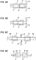
- Figs. 9A to 9D are schematic views of first to fourth variations of the cooling members 41, 42 of the first embodiment. Note that arrows in Figs. 9A to 9D indicate a refrigerant flow.
- refrigerant flows in the cooling member 42 configured to cool the power element 32, the cooling member 41 configured to cool the power element 31, the cooling member 41, and the cooling member 42 in this order in a pipe 80 forming the branched refrigerant circuit 5.
- cooling members 41, 42 are replaced with a single refrigerant jacket 45 configured to cool the power element 31 and the power element 32.
- the cooling member 41 is a refrigerant jacket configured to cool the power element 31, and the cooling member 42 is a refrigerant jacket 42 configured to cool the power element 32.
- the refrigerant jacket 41 is attached to a cooling section 80a as part of the refrigerant pipe 80.
- the refrigerant jacket 42 is attached to a cooling section 80b as part of the refrigerant pipe 80.
- the cooling section 80a and the cooling section 80b are connected in parallel with each other with respect to upstream and downstream sides of the pipe 80.
- the cooling sections 80a, 80b are not bent in a U-shape as in the first to fourth embodiments and the first to third variations, and extend substantially linearly.
Landscapes
- Engineering & Computer Science (AREA)
- Mechanical Engineering (AREA)
- General Engineering & Computer Science (AREA)
- Physics & Mathematics (AREA)
- Thermal Sciences (AREA)
- Chemical & Material Sciences (AREA)
- Combustion & Propulsion (AREA)
- Air Conditioning Control Device (AREA)
Abstract
Description
- The present invention relates to an air conditioner.
- Typically, in an air conditioner configured to perform a vapor compression type refrigerating cycle by means of refrigerant circulation, an electric circuit such as an inverter circuit configured to control the rotation speed of a compressor is mounted for controlling an operation state of the compressor. Generally, a power element generating high heat due to power control or supply is used for the inverter circuit.
- In the typical air conditioner, a section configured to cool the power element is provided to prevent the power element from having a higher temperature than an operable temperature. A refrigerant cooling technique for cooling the power element by refrigerant flowing in a refrigerant circuit has been proposed as one example of such a cooling section.
-
Patent Document 1 describes that a "main refrigerant circuit (11) including a compressor (32), a heat source side heat exchanger (30), a first expansion valve (34), and a utilization side heat exchanger (20) and configured such that refrigerant flows in the main refrigerant circuit (11)" and a "branched refrigerant circuit (12) configured such that refrigerant branched from the main refrigerant circuit (11) flows in the branched refrigerant circuit (12)" are provided, a "second expansion valve (61, 62) provided at the branched refrigerant circuit (12) and configured to expand refrigerant flowing into a cooling section (53) and a control section (60) configured to control the second expansion valve (61, 62) are further provided," and therefore, "the cooling capacity of the cooling section (53) can be controlled and the temperature of an electric component (50a to 50d) (see attachedFig. 4 ) can be properly adjusted." - Patent Document 2 describes that "multiple compressors (23A, 23B) are provided, a refrigerant adjustment mechanism adjusts the amount of refrigerant supplied to each cooling section (37A, 37B) corresponding to a power substrate (35A, 35B) of each compressor (23A, 23B) according to operation or performance of each compressor (23A, 23B) in a case where the power substrate (35A, 35B) and the cooling section (37A, 37B) are provided for each compressor (23A, 23B)," and therefore, "cooling of the electric components (35A, 35B) by refrigerant flowing in a refrigerant circuit (18) can be more efficiently performed."
-
- Patent Document 1:
JP-A-2006-170469 Figs. 1 and4 and the like) - Patent Document 2:
JP-A-2011-117677 Fig. 1 and the like) - When the temperature of refrigerant cooling the power element becomes too low, the surface temperature of the power element or the surrounding temperature thereof reaches lower than the dew-point temperature of surrounding air, and therefore, there is a probability that dew condensation occurs at a surface of the power element or the periphery thereof.
- However, in the case of the structure disclosed in Patent Document 2, i.e., in a case where the multiple power elements are cooled by the cooling sections, the power element corresponding to the operating compressor generates heat, and on the other hand, the power element corresponding to the stopped compressor does not generate heat. Even in this case, all of the power elements are cooled by the cooling sections. Thus, the power element corresponding to the stopped compressor and the periphery thereof reach equal to or lower than a dew point, and there is a probability that dew condensation occurs.
- Moreover, even in the case of the structure disclosed in
Patent Document 1, i.e., a case where the expansion valve is provided at the branched refrigerant circuit to control the cooling capacity of the cooling section, all of the power elements are cooled by the cooling section. Thus, the power element corresponding to the stopped compressor and the periphery thereof reach equal to or lower than the dew point, and there is a probability that dew condensation occurs. - The present invention has been made in view of the above-described situation, and is intended to provide an air conditioner configured so that occurrence of dew condensation at a heat generator and the periphery thereof can be reduced.
- For solving the above-described problems, an air conditioner of a first aspect of the invention includes a main refrigerant circuit including a compressor, a heat source side heat exchanger, a first expansion valve, and a utilization side heat exchanger and configured such that refrigerant flows in the main refrigerant circuit, a sub refrigerant circuit including a cooling member configured such that refrigerant branched from the main refrigerant circuit flows in the cooling member and configured such that refrigerant branched from the main refrigerant circuit flows in the sub refrigerant circuit, and a heat generator to be cooled by the cooling member. A pipe in which part of refrigerant discharged from the compressor flows is connected to the cooling member of the sub refrigerant circuit.
- An air conditioner of a second aspect of the invention includes a main refrigerant circuit including a compressor, a heat source side heat exchanger, a first expansion valve, and a utilization side heat exchanger and configured such that refrigerant flows in the main refrigerant circuit, a sub refrigerant circuit including a cooling member configured such that refrigerant branched from the main refrigerant circuit flows in the cooling member and configured such that refrigerant branched from the main refrigerant circuit flows in the sub refrigerant circuit, a heat generator to be cooled by the cooling member, and a pipe in which part of refrigerant discharged from the compressor flows into the cooling member. The pipe is connected to the main refrigerant circuit.
- According to the present invention, in an air conditioner including a cooler configured to cool multiple heat generators by refrigerant flowing in a refrigerant circuit, occurrence of dew condensation at the heat generator corresponding to a stopped one of the multiple heat generators and the periphery thereof can be reduced.
-
-
Fig. 1A is a diagram of a refrigerating cycle of an air conditioner according to a first embodiment. -
Fig. 1B is a diagram in a case where a heat source side heat exchanger according to the first embodiment is a heat exchanger configured to exchange heat between water and refrigerant. -
Fig. 2A is a partial front view of an inverter device. -
Fig. 2B is a partial view of the inverter device from the direction of an arrow A. -
Fig. 3 is a diagram of a control system of the air conditioner. -
Fig. 4 is a chart of a control flow of the air conditioner of the first embodiment. -
Fig. 5 is a control flow chart of an air conditioner of a second embodiment. -
Fig. 6 is a diagram of one example of a refrigerating cycle of an air conditioner according to a third embodiment. -
Fig. 7 is a diagram of another example of the refrigerating cycle of the air conditioner according to the third embodiment. -
Fig. 8 is a diagram of one example of a refrigerating cycle of an air conditioner according to a fourth embodiment. -
Fig. 9A is a schematic view of a first variation of cooling members of the first embodiment. -
Fig. 9B is a schematic view of a second variation of the cooling members of the first embodiment. -
Fig. 9C is a schematic view of a third variation of the cooling members of the first embodiment. -
Fig. 9D is a schematic view of a fourth variation of the cooling members of the first embodiment. - Hereinafter, embodiments of the present invention will be described with reference to the drawings. Unless otherwise specified below, refrigerant or a refrigerating cycle indicates refrigerant or a refrigerating cycle available for cooling, heating, or both.
-
Fig. 1A is a diagram of a refrigerating cycle of anair conditioner 1 according to a first embodiment.Fig. 1B is a diagram in a case where a heat sourceside heat exchanger 13 according to the first embodiment is a heat exchanger configured to exchange heat between water and refrigerant. - The
air conditioner 1 according to the first embodiment as illustrated inFig. 1A includes a heat source unit 2 (e.g., an outdoor unit) configured to supply heat, and a utilization unit 3 (e.g., an indoor unit) configured to performing cooling/heating by means of such a heat. The heat source unit 2 and the utilization unit 3 are connected to each other viarefrigerant pipes - The utilization unit 3 includes a utilization
side expansion valve 17 as a depressurization device on a utilization unit 3 side, a utilizationside heat exchanger 16, and anair blower 18. Theair blower 18 is configured to send air into the utilizationside heat exchanger 16 to promote heat exchange with air in the utilizationside heat exchanger 16. - The heat source unit 2 has a
main refrigerant circuit 4, a branched refrigerant circuit (a sub refrigerant circuit) 5, and a discharged gas branching refrigerant circuit (pipe) 6. - The main
refrigerant circuit 4 is a main circuit for performing, e.g., cooling/heating by theair conditioner 1. - The branched
refrigerant circuit 5 is a circuit in which low-temperature refrigerant flows to cool power elements (heat generators) 31, 32 used for control of theair conditioner 1. - The discharged gas branching
refrigerant circuit 6 is a circuit in which high-temperature refrigerant flows to reduce frosting of thepower elements - The main
refrigerant circuit 4 is a circuit connected to main components of the heat source unit 2. - The main
refrigerant circuit 4 includes afirst compressor 11, asecond compressor 12, a four-way valve 20 functioning to switch a refrigerant flow path direction between cooling operation and heating operation, a gasside closing valve 21, a liquidside closing valve 22, the heat sourceside heat exchanger 13, and afirst expansion valve 15 as a depressurization device on a heat source unit 2 side. - The heat source unit 2 described herein includes an
air blower 14 configured to send air into the heat sourceside heat exchanger 13 to promote heat exchange in a case where the heat sourceside heat exchanger 13 is a heat exchanger configured to exchange heat between air and refrigerant flowing in the mainrefrigerant circuit 4. - Note that as illustrated in
Fig. 1B , theair blower 14 can be omitted in a case where the heat sourceside heat exchanger 13 is the heat exchanger configured to exchange heat between water and refrigerant. - In the cooling operation of the
air conditioner 1, refrigerant discharged from the first andsecond compressors side heat exchanger 13 through the four-way valve 20. Such refrigerant releases heat to air or water by heat exchange, and is condensed. High-pressure gas refrigerant discharged from the first andsecond compressors side heat exchanger 13. When passing through thefirst expansion valve 15, the high-pressure liquid refrigerant is depressurized according to the degree of opening of thefirst expansion valve 15. - That is, the refrigerant is less depressurized as the degree of opening of the
first expansion valve 15 increases, and is more depressurized as the degree of opening of thefirst expansion valve 15 decreases. Note that in the cooling operation, thefirst expansion valve 15 is sometimes in a fully-open state. The liquid refrigerant depressurized by thefirst expansion valve 15 is sent to the utilization unit 3 by way of the liquidside closing valve 22 and therefrigerant pipe 1L. - The low-pressure liquid refrigerant (or the refrigerant in an air-liquid two-phase state) sent to the utilization unit 3 is further depressurized when passing through the utilization
side expansion valve 17, and is sent to the utilizationside heat exchanger 16. The low-pressure refrigerant sent in the air-liquid two-phase state to the utilizationside heat exchanger 16 absorbs heat by heat exchange with indoor air, and cooling is performed. Such refrigerant is evaporated into low-pressure gas refrigerant. The low-pressure gas refrigerant is sent to the heat source unit 2 by way of therefrigerant pipe 1V, and is sucked into the first andsecond compressors side closing valve 21 and the four-way valve 20. - In the heating operation of the
air conditioner 1, refrigerant discharged from the first andsecond compressors way valve 20, the gasside closing valve 21, and therefrigerant pipe 1V. The high-pressure gas refrigerant sent to the utilization unit 3 releases heat by heat exchange with indoor air in the utilizationside heat exchanger 16, and heating is performed. By heat exchange in the utilizationside heat exchanger 16, the high-pressure gas refrigerant releases heat, and is condensed into high-pressure liquid refrigerant. When passing through the utilizationside expansion valve 17, the high-pressure liquid refrigerant is depressurized according to the degree of opening of the utilizationside expansion valve 17. Note that the utilizationside expansion valve 17 is sometimes in a fully-open state. - The refrigerant having passed through the utilization
side expansion valve 17 is sent to the heat source unit 2 by way of therefrigerant pipe 1L. The liquid refrigerant sent to the heat source unit 2 is further depressurized according to the degree of opening when passing through thefirst expansion valve 15 by way of the liquidside closing valve 22, and flows into the heat sourceside heat exchanger 13. The low-pressure refrigerant flowing into the heat sourceside heat exchanger 13 in an air-liquid two-phase state absorbs heat from external air or water, and is evaporated. Thus, the low-pressure refrigerant in the air-liquid two-phase state turns into low-pressure gas refrigerant. The low-pressure gas refrigerant having flowed out of the heat sourceside heat exchanger 13 is sucked into the first andsecond compressors way valve 20. - The branched
refrigerant circuit 5 is a circuit in which refrigerant branched from the mainrefrigerant circuit 4 flows. The branchedrefrigerant circuit 5 is configured to cool thepower elements - The branched
refrigerant circuit 5 is provided in parallel with the mainrefrigerant circuit 4 at a portion from a portion between the heat sourceside heat exchanger 13 and thefirst expansion valve 15 of the mainrefrigerant circuit 4 to a portion between thefirst expansion valve 15 and the liquidside closing valve 22. The branchedrefrigerant circuit 5 includes a coolingmember 41 for thepower element 31, a coolingmember 42 for thepower element 32, and asecond expansion valve 43. - By means of the
second expansion valve 43, the branchedrefrigerant circuit 5 is brought into a use state only in the case of cooling thepower elements power elements second expansion valve 43 is closed, and the branchedrefrigerant circuit 5 is brought into a non-use state. - The cooling
member 41 is a member configured to cool thepower element 31 of which the temperature is high due to heat generation. The coolingmember 42 is a member configured to cool thepower element 32 of which the temperature is high due to heat generation. - In the cooling operation, part of refrigerant flowing in the main
refrigerant circuit 4 is branched into the branchedrefrigerant circuit 5 from the portion between the heat sourceside heat exchanger 13 and thefirst expansion valve 15. The branched refrigerant flows in thesecond expansion valve 43, the coolingmember 41, and the coolingmember 42 in this order, and joins the mainrefrigerant circuit 4 at the portion between thefirst expansion valve 15 and the liquidside closing valve 22. - On the other hand, in the heating operation, part of refrigerant flowing in the main
refrigerant circuit 4 is branched into the branchedrefrigerant circuit 5 from the portion between the liquidside closing valve 22 and thefirst expansion valve 15. The branched refrigerant flows, contrary to the cooling operation, in the coolingmember 42, the coolingmember 41, and thesecond expansion valve 43 in this order, and joins the mainrefrigerant circuit 4 at a position between thefirst expansion valve 15 and the heat sourceside heat exchanger 13. That is, the flow of refrigerant in the branched refrigerant circuit is reversed between the cooling operation and the heating operation. - The flow rate of refrigerant flowing in the branched
refrigerant circuit 5 may be the same as the flow rate of refrigerant flowing in the mainrefrigerant circuit 4, but may be lower than the flow rate of refrigerant flowing in the mainrefrigerant circuit 4. In the former case, the cooling capacities of the coolingmembers power elements members power elements power elements - Note that in an example of
Fig. 1A , thepower element 31 of thepower elements member 41 of the coolingmembers second expansion valve 43, but thepower element 32 and the coolingmember 42 may be provided near thesecond expansion valve 43. - The discharged gas branching
refrigerant circuit 6 is a circuit configured to heat thepower elements power elements refrigerant circuit 6, refrigerant branched fromdischarge pipes second compressors - The discharged gas branching
refrigerant circuit 6 is provided in parallel with the mainrefrigerant circuit 4 at a portion from a portion between each of the first andsecond compressors way valve 20 to a portion between thesecond expansion valve 43 and the coolingmember - The discharged gas branching
refrigerant circuit 6 includes anelectromagnetic valve 50 configured to switch the discharged gas branchingrefrigerant circuit 6 between the use state and the non-use state. - The
electromagnetic valve 50 is closed in a normal state (a steady state), and the discharged gas branchingrefrigerant circuit 6 is in the non-use state. When theelectromagnetic valve 50 is opened, part of high-pressure high-temperature gas refrigerant discharged from the first andsecond compressors refrigerant circuit 6 from the portion between each of the first andsecond compressors way valve 20, and the discharged gas branchingrefrigerant circuit 6 is brought into the use state. Such refrigerant joins the branchedrefrigerant circuit 5 at the portion between thesecond expansion valve 43 and the coolingmember -
Fig. 2A is a partial front view of aninverter device 30, andFig. 2B is a partial view of theinverter device 30 from the direction of an arrow A. - The
inverter device 30 is a circuit configured to control the power of theair conditioner 1, and the temperature thereof is increased due to heat generation from thepower elements - As illustrated in
Fig. 2A , thepower elements circuit board 33 in theinverter device 30. - As illustrated in
Fig. 2B , the coolingmembers refrigerant jackets refrigerant pipe 44 embedded in each of therefrigerant jackets refrigerant circuit 4 flows in therefrigerant pipe 44 in the branched refrigerant circuit 5 (seeFig. 1A ). The coolingmembers - Note that as long as the thermal conductivity is high, other materials than metal may be used for the
refrigerant jackets - As illustrated in
Fig. 2A , therefrigerant jackets refrigerant jackets power elements - That is, one surface 43a1, 43bl of each of the
refrigerant jackets power elements refrigerant pipe 44 of the branchedrefrigerant circuit 5 absorbs heat from thepower elements refrigerant jackets - The cooling
members section temperature sensors section temperature sensors refrigerant jackets section temperature sensors members power element section temperature sensors power elements power elements -
Fig. 3 is a diagram of a control system of theair conditioner 1. - A
control section 60 is configured to control operation of theair conditioner 1 based on detection signals received from various sensors provided at theair conditioner 1. Thecontrol section 60 may be provided at the heat source unit 2, or may be provided at the utilization unit 3. Alternatively, thecontrol section 60 may be provided separately at the heat source unit 2 and the utilization unit 3 in terms of functions. - The
control section 60 includes, for example, a not-shown microcomputer. Thecontrol section 60 controls the first andsecond compressors 11, 12 (thepower elements 31, 32), the four-way valve 20, thefirst expansion valve 15, thesecond expansion valve 43, theelectromagnetic valve 50, and theair blower 14 mounted on the heat source unit 2, the utilizationside expansion valve 17, and theair blower 18. Measurement values of the coolingsection temperature sensors members control section 60. - Hereinafter, a specific control flow of the
air conditioner 1 will be described with reference to a control flowchart illustrated inFig. 4. Fig. 4 is a chart of the control flow of theair conditioner 1 of the first embodiment. - The control flow of the
air conditioner 1 is executed by the microcomputer mounted on the control section 60 (seeFig. 3 ) provided at the heat source unit 2, for example. - When operation of the
air conditioner 1 begins, thecontrol section 60 detects, at a step S1, each of the cooling section temperatures of therefrigerant jackets section temperature sensors Fig. 2A ). - Subsequently, at a step S2, the
control section 60 adjusts the degree of opening of thesecond expansion valve 43 of the branchedrefrigerant circuit 5 such that each of the cooling section temperatures of therefrigerant jackets refrigerant jackets second expansion valve 43 is opened to promote cooling, and the flow rate of refrigerant flowing in the coolingmembers refrigerant jackets second expansion valve 43 is closed, and the flow rate of refrigerant flowing in the coolingmembers second expansion valve 43, the coolingmember 41, and the coolingmember 42 in this order in the cooling operation, and flows in the coolingmember 42, the coolingmember 41, and thesecond expansion valve 43 in this order in the heating operation. - The target cooling section temperature described herein may be a fixed temperature. Alternatively, a necessary cooling capacity changes according to the amount of heat generation from the
power elements second compressors members members members Fig. 2A or the temperature of refrigerant therearound. Note that for reducing occurrence of dew condensation, the target cooling section temperature is set higher than a later-described dew condensation temperature. - At a step S3, the
control section 60 determines whether or not a dew condensation occurrence condition under which it is determined that dew condensation might occur at thepower elements - In a case where the dew condensation occurrence condition is not satisfied (NO at the step S3), the
control section 60 transitions to a step S4. On the other hand, in a case where the dew condensation occurrence condition is satisfied (YES at the step S3), thecontrol section 60 transitions to a step S6. - Determination on whether or not the dew condensation occurrence condition is satisfied as described herein is made based on whether or not the temperatures of the cooling
section temperature sensors power elements refrigerant jackets power elements refrigerant jackets - At the step S4, the
control section 60 determines whether or not theelectromagnetic valve 50 is opened. In a case where theelectromagnetic valve 50 is not opened (NO at the step S4), thecontrol section 60 returns to the step S1. In a case where theelectromagnetic valve 50 is opened (YES at the step S4), thecontrol section 60 transitions to a step S5. - At the step S5, the
control section 60 returns to the step S1 after theelectromagnetic valve 50 has been closed. That is, the electromagnetic valve is closed. - At the step S6, the
control section 60 determines whether or not theelectromagnetic valve 50 is closed. In a case where theelectromagnetic valve 50 is not closed (NO at the step S6), thecontrol section 60 returns to the step S1. In a case where theelectromagnetic valve 50 is closed (YES at the step S6), thecontrol section 60 transitions to a step S7. - At the step S7, the
control section 60 returns to the step S1 after theelectromagnetic valve 50 has been opened. - As described above, in a case where the
multiple power elements members power element 31 corresponding to the operatingfirst compressor 11 generates heat, and on the other hand, thepower element 32 corresponding to the stoppedsecond compressor 12 does not generate heat, for example. Even in this case, all of thepower elements members power element 32 corresponding to the stoppedsecond compressor 12 and the surrounding temperature thereof decrease to equal to or lower than a dew point and dew condensation occurs. - Even in a case where the
second expansion valve 43 is provided at the branchedrefrigerant circuit 5 to control the cooling capacity of a cooling section, all of thepower elements members power element 32 corresponding to the stoppedsecond compressor 12 and the surrounding temperature thereof decrease to equal to or lower than the dew point and dew condensation occurs. - Determination on whether or not dew condensation occurs at the
power elements members power elements refrigerant jackets Fig. 1B , in a case where the heat sourceside heat exchanger 13 is the heat exchanger configured to exchange heat between water and refrigerant, a water temperature and the surrounding temperatures of thepower elements refrigerant jackets power elements refrigerant jackets - When the water temperature is low, the temperature of refrigerant flowing in the cooling
members power elements refrigerant jackets power elements - When the
electromagnetic valve 50 is opened, part of high-pressure high-temperature gas refrigerant discharged from the first andsecond compressors refrigerant circuit 6 from the portion between each of the first andsecond compressors way valve 20, and joins the branchedrefrigerant circuit 5 between thesecond expansion valve 43 and the coolingmember - In a case where the temperatures of the cooling
members control section 60 controls thesecond expansion valve 43 of the branchedrefrigerant circuit 5 in a closing direction, and therefore, the flow rate of refrigerant flowing in thesecond expansion valve 43 is decreased. - Thus, in the case of the cooling operation, most of refrigerant having joined the branched
refrigerant circuit 5 flows in the coolingmember 41 and the coolingmember 42 in this order, and joins the mainrefrigerant circuit 4 at the portion between thefirst expansion valve 15 and the liquidside closing valve 22. - On the other hand, in the case of the heating operation, the
second expansion valve 43 is similarly closed such that most of refrigerant having joined the branchedrefrigerant circuit 5 flows in the coolingmember 41 and the coolingmember 42 in this order and joins the mainrefrigerant circuit 4 at the portion between thefirst expansion valve 15 and the liquidside closing valve 22. - Thus, by refrigerant from the discharged gas branching
refrigerant circuit 6, the temperatures of the coolingmembers power elements - Even in a case where both of the first and
second compressors members electromagnetic valve 50 can be opened to increase the temperatures of the coolingmembers - As described above, the
air conditioner 1 includes the mainrefrigerant circuit 4 and the branchedrefrigerant circuit 5. The mainrefrigerant circuit 4 includes the first andsecond compressors side heat exchanger 13, thefirst expansion valve 15, and the utilizationside heat exchanger 16, and refrigerant flows in the mainrefrigerant circuit 4. The branchedrefrigerant circuit 5 includes a pipe of the discharged gas branchingrefrigerant circuit 6 in which part of refrigerant discharged from the first andsecond compressors refrigerant circuit 4 flows in the branchedrefrigerant circuit 5. - In the
air conditioner 1, high-temperature refrigerant discharged from the first andsecond compressors refrigerant circuit 5 as the sub refrigerant circuit so that the temperature of refrigerant flowing in the coolingmembers power elements multiple power elements - Moreover, the flow rate of refrigerant flowing in the branched
refrigerant circuit 5 as the sub refrigerant circuit is decreased as compared to the flow rate of refrigerant flowing in the mainrefrigerant circuit 4 so that lowering of performance in the cooling operation or the heating operation can be suppressed and frosting of thepower elements -
Fig. 5 illustrates a control flowchart of anair conditioner 1 of a second embodiment. - When an
electromagnetic valve 50 of a discharged gas branchingrefrigerant circuit 6 is opened such that refrigerant flows from a mainrefrigerant circuit 4 to a branchedrefrigerant circuit 5, the amount of refrigerant in the mainrefrigerant circuit 4 is decreased, and a cooling/heating capacity is influenced. - For this reason, in the second embodiment, opening of the
electromagnetic valve 50 is reduced such that lowering of the cooling/heating capacity is suppressed. - A control flow of the second embodiment is partially the same as that of the second embodiment illustrated in
Fig. 4 , and therefore, only control different from that of the first embodiment will be described. - Unlike the first embodiment, in a case where a dew condensation occurrence condition is satisfied at a step S3 (YES at the step S3), a
control section 60 transitions to a step S8 (Fig. 5 ) in the second embodiment. - At the step S8, the
control section 60 determines whether or not asecond expansion valve 43 is fully closed. This is because even when thesecond expansion valve 43 is fully closed, theelectromagnetic valve 50 is opened to use the discharged gas branchingrefrigerant circuit 6 for the purpose of prevention of dew condensation as far as the temperatures ofpower elements - In a case where the
second expansion valve 43 is not fully closed (NO at the step S8), there is room for decreasing the degree of opening of thesecond expansion valve 43, and therefore, the processing returns to a step S1. - In a case where the
second expansion valve 43 is fully closed (YES at the step S8), there is no room for decreasing the degree of opening of thesecond expansion valve 43, and therefore, the processing transitions to a step S6. - As described above, when the
electromagnetic valve 50 is opened such that part of gas refrigerant discharged from first andsecond compressors refrigerant circuit 6, the flow rate of refrigerant flowing in a heat sourceside heat exchanger 13 decreases to lower a cooling capacity in cooling operation, and the flow rate of refrigerant flowing in a utilizationside heat exchanger 16 decreases to lower a heating capacity in heating operation. Thus, it is better to reduce excessive opening/closing of theelectromagnetic valve 50. - As described in the first embodiment, in a case where the temperatures of cooling
members control section 60 controls thesecond expansion valve 43 in a closing direction, and therefore, the flow rate of refrigerant flowing in thesecond expansion valve 43 is decreased. Thus, in the second embodiment, even when thesecond expansion valve 43 is closed to decrease the flow rate of refrigerant flowing in the coolingmembers electromagnetic valve 50 is opened only in a case where the temperatures of the coolingmembers - At the step S6, the
control section 60 determines whether or not theelectromagnetic valve 50 is closed. - In a case where the
electromagnetic valve 50 is not closed, i.e., theelectromagnetic valve 50 is opened (NO at the step S6), the processing returns to the step S1. - In a case where the
electromagnetic valve 50 is closed (YES at the step S6), the processing transitions to a step S7, and thecontrol section 60 opens theelectromagnetic valve 50. Thereafter, thecontrol section 60 returns to the step S1. - By the control above, excessive opening/closing of the
electromagnetic valve 50 can be reduced. Excessive opening/closing of theelectromagnetic valve 50 is reduced so that lowering of the cooling capacity and the heating capacity in the case of using the discharged gas branchingrefrigerant circuit 6 can be suppressed. -
Fig. 6 is a diagram of one example of a refrigerating cycle of anair conditioner 1 according to a third embodiment. - In the first embodiment illustrated in
Fig. 1A , the refrigerant circuit configured such that the multiple first andsecond compressors multiple power elements members Fig. 6 , a refrigerant circuit configured such that asingle compressor 11, asingle power element 31, and asingle cooling member 41 are provided at a heat source unit 2 may be employed. Moreover, inFig. 6 , anexpansion valve 51 is used instead of anelectromagnetic valve 50. The degree of opening of theexpansion valve 51 is controlled so that the percentage of the flow rate of refrigerant flowing into a discharged gas branchingrefrigerant circuit 6 with respect to gas refrigerant discharged from thecompressor 11 can be adjusted. -
Fig. 7 is a diagram of another example of the refrigerating cycle of theair conditioner 1 according to the third embodiment. - As illustrated in
Fig. 7 , the discharged gas branchingrefrigerant circuit 6 may include multipleelectromagnetic valves electromagnetic valves refrigerant circuit 6 with respect to gas refrigerant discharged from thecompressor 11 can be finely adjusted, i.e., fine-adjusted. - In the embodiment illustrated in
Fig. 1A , the discharged gas branchingrefrigerant circuit 6 is branched from the portion between each of the first andsecond compressors way valve 20 in the mainrefrigerant circuit 4, and joins the portion between thesecond expansion valve 43 and the coolingmember -
Fig. 8 is a diagram of one example of a refrigerating cycle of anair conditioner 1 according to a fourth embodiment. - In the fourth embodiment, it is configured such that a
pipe 6a of a discharged gas branchingrefrigerant circuit 6 extends in parallel with a branchedrefrigerant circuit 5 through a coolingmember 41 and joins a portion between afirst expansion valve 15 and a liquidside closing valve 22. In the fourth embodiment, when anelectromagnetic valve 50 is opened, part of high-pressure high-temperature gas refrigerant discharged from acompressor 11 flows into the discharged gas branchingrefrigerant circuit 6 from a portion between thecompressor 11 and a four-way valve 20, and flows in the coolingmember 41 of the branchedrefrigerant circuit 5. Then, the refrigerant joins a mainrefrigerant circuit 4 between thefirst expansion valve 15 and the liquidside closing valve 22. - Thus, high-pressure gas from the discharged gas branching
refrigerant circuit 6 can flow in the coolingmember 41 regardless of opening/closing of asecond expansion valve 43. - In this case, refrigerant from the discharged gas branching
refrigerant circuit 6 flows in the coolingmember 41, and therefore, a cooling section temperature (the temperatures of the coolingmember 41 and a power element 31) can be increased. Thus, occurrence of dew condensation at thepower element 31 and the periphery thereof can be reduced. - In the above-described first embodiment, the cooling
members Figs. 2A and 2B have been described as an example, but the present invention is not limited to above.Figs. 9A to 9D are schematic views of first to fourth variations of the coolingmembers Figs. 9A to 9D indicate a refrigerant flow. - In the first variation illustrated in
Fig. 9A , refrigerant flows in the coolingmember 42 configured to cool thepower element 32, the coolingmember 41 configured to cool thepower element 31, the coolingmember 41, and the coolingmember 42 in this order in apipe 80 forming the branchedrefrigerant circuit 5. - In the second variation illustrated in
Fig. 9B , the coolingmembers refrigerant jacket 45 configured to cool thepower element 31 and thepower element 32. - In the third variation illustrated in
Fig. 9C , the coolingmember 41 is a refrigerant jacket configured to cool thepower element 31, and the coolingmember 42 is arefrigerant jacket 42 configured to cool thepower element 32. Therefrigerant jacket 41 is attached to acooling section 80a as part of therefrigerant pipe 80. Therefrigerant jacket 42 is attached to acooling section 80b as part of therefrigerant pipe 80. In the third variation, thecooling section 80a and thecooling section 80b are connected in parallel with each other with respect to upstream and downstream sides of thepipe 80. - In the fourth variation illustrated in
Fig. 9D , the coolingsections -
- 1. Note that in the above-described embodiments, the
power elements power elements - 2. Note that the present invention is not limited to the above-described embodiments and variations, and includes various modifications. For example, the above-described embodiments are for detailed description for the sake of easy understanding of the present invention, and are not limited to those including all of the configurations described above. Moreover, for some of the configurations of the embodiments, addition/omission/replacement of other configurations may be made.
-
- 1
- air conditioner
- 4
- main refrigerant circuit
- 5
- sub refrigerant circuit (branched refrigerant circuit)
- 6
- pipe
- 6a
- pipe
- 11
- first compressor (compressor)
- 12
- second compressor (compressor)
- 13
- heat source side heat exchanger
- 15
- first expansion valve
- 16
- utilization side heat exchanger
- 31
- power element (heat generator, first heat generator)
- 32
- power element (heat generator, second heat generator)
- 41, 42
- cooling member
- 43
- second expansion valve
- 60
- control section
Claims (7)
- An air conditioner comprising:a main refrigerant circuit including a compressor, a heat source side heat exchanger, a first expansion valve, and a utilization side heat exchanger and configured such that refrigerant flows in the main refrigerant circuit;a sub refrigerant circuit including a cooling member configured such that refrigerant branched from the main refrigerant circuit flows in the cooling member and configured such that refrigerant branched from the main refrigerant circuit flows in the sub refrigerant circuit; anda heat generator to be cooled by the cooling member,wherein a pipe in which part of refrigerant discharged from the compressor flows is connected to the cooling member of the sub refrigerant circuit.
- The air conditioner according to claim 1, wherein
the cooling member includes multiple cooling members. - The air conditioner according to claim 1, wherein
a flow rate of refrigerant flowing in the sub refrigerant circuit is lower than a flow rate of refrigerant flowing in the main refrigerant circuit. - The air conditioner according to claim 2, wherein
the compressor includes a first compressor and a second compressor,
the heat generator includes a first heat generator for controlling the first compressor and a second heat generator for controlling the second compressor, and
the first heat generator and the second heat generator are cooled by the multiple cooling members. - The air conditioner according to claim 1, further comprising:
a second expansion valve provided at the sub refrigerant circuit and configured to expand refrigerant flowing into the cooling member. - The air conditioner according to claim 1, further comprising:a second expansion valve provided at the sub refrigerant circuit and configured to expand refrigerant flowing into the cooling member; anda control section configured to perform control such that the second expansion valve is operated in a closing direction in a case where a cooling capacity of the cooling member needs to be lowered and perform control such that part of refrigerant discharged from the compressor flows into the cooling member in a case where the cooling capacity of the cooling member needs to be further lowered.
- An air conditioner comprising:a main refrigerant circuit including a compressor, a heat source side heat exchanger, a first expansion valve, and a utilization side heat exchanger and configured such that refrigerant flows in the main refrigerant circuit;a sub refrigerant circuit including a cooling member configured such that refrigerant branched from the main refrigerant circuit flows in the cooling member and configured such that refrigerant branched from the main refrigerant circuit flows in the sub refrigerant circuit;a heat generator to be cooled by the cooling member; anda pipe in which part of refrigerant discharged from the compressor flows into the cooling member,wherein the pipe is connected to the main refrigerant circuit.
Applications Claiming Priority (1)
| Application Number | Priority Date | Filing Date | Title |
|---|---|---|---|
| PCT/JP2017/036550 WO2019069470A1 (en) | 2017-10-06 | 2017-10-06 | Air conditioner |
Publications (2)
| Publication Number | Publication Date |
|---|---|
| EP3693678A1 true EP3693678A1 (en) | 2020-08-12 |
| EP3693678A4 EP3693678A4 (en) | 2021-04-28 |
Family
ID=65994252
Family Applications (1)
| Application Number | Title | Priority Date | Filing Date |
|---|---|---|---|
| EP17923982.7A Withdrawn EP3693678A4 (en) | 2017-10-06 | 2017-10-06 | Air conditioner |
Country Status (6)
| Country | Link |
|---|---|
| US (1) | US11231185B2 (en) |
| EP (1) | EP3693678A4 (en) |
| JP (1) | JP6538290B1 (en) |
| KR (1) | KR102253932B1 (en) |
| CN (1) | CN109891165B (en) |
| WO (1) | WO2019069470A1 (en) |
Families Citing this family (9)
| Publication number | Priority date | Publication date | Assignee | Title |
|---|---|---|---|---|
| JP7241866B2 (en) * | 2019-05-29 | 2023-03-17 | 三菱電機株式会社 | refrigeration cycle equipment |
| JP6636200B2 (en) * | 2019-06-04 | 2020-01-29 | 日立ジョンソンコントロールズ空調株式会社 | Air conditioner |
| WO2021068327A1 (en) * | 2019-10-12 | 2021-04-15 | 青岛海信日立空调系统有限公司 | Air conditioner outdoor unit and control method |
| CN110762788A (en) * | 2019-10-12 | 2020-02-07 | 青岛海信日立空调系统有限公司 | Outdoor unit of air conditioner, circulation system and control method |
| CN112648685A (en) * | 2019-10-12 | 2021-04-13 | 青岛海信日立空调系统有限公司 | Air conditioner outdoor unit, circulating system and control method |
| CN110822564A (en) * | 2019-11-26 | 2020-02-21 | 广东美的制冷设备有限公司 | Heat dissipation assembly, air conditioning system and heat dissipation control method of air conditioning system |
| CN111442417B (en) * | 2020-04-09 | 2022-04-19 | 广东美的制冷设备有限公司 | Air conditioner, control method and control device thereof, and computer readable storage medium |
| CN114543194B (en) * | 2020-11-26 | 2024-04-26 | 广东美的制冷设备有限公司 | Heat dissipation device, control method thereof, controller, air conditioner and readable storage medium |
| CN113865138B (en) * | 2021-09-08 | 2023-04-11 | 美的集团武汉暖通设备有限公司 | Air source heat pump system and control method of air source heat pump |
Family Cites Families (18)
| Publication number | Priority date | Publication date | Assignee | Title |
|---|---|---|---|---|
| JP2005133976A (en) * | 2003-10-28 | 2005-05-26 | Hitachi Ltd | Air conditioner |
| JP4687093B2 (en) | 2004-12-13 | 2011-05-25 | ダイキン工業株式会社 | Air conditioner |
| JP5446064B2 (en) | 2006-11-13 | 2014-03-19 | ダイキン工業株式会社 | Heat exchange system |
| CN102575882B (en) * | 2009-10-20 | 2014-09-10 | 三菱电机株式会社 | Heat pump device |
| JP2011117677A (en) | 2009-12-04 | 2011-06-16 | Daikin Industries Ltd | Outdoor unit for air conditioning device |
| JP2011122779A (en) * | 2009-12-11 | 2011-06-23 | Toshiba Carrier Corp | Refrigerating cycle device |
| KR101324935B1 (en) | 2011-10-11 | 2013-11-01 | 엘지전자 주식회사 | Air conditioner |
| WO2013057832A1 (en) * | 2011-10-21 | 2013-04-25 | トヨタ自動車株式会社 | Cooling device and control method for cooling device |
| EP2796810A4 (en) * | 2011-12-19 | 2016-03-16 | Toyota Motor Co Ltd | COOLING DEVICE |
| US8950201B2 (en) * | 2012-03-30 | 2015-02-10 | Trane International Inc. | System and method for cooling power electronics using heat sinks |
| JP5408285B2 (en) * | 2012-04-27 | 2014-02-05 | ダイキン工業株式会社 | Refrigerator, electrical component unit and refrigeration system |
| US9982929B2 (en) * | 2012-11-20 | 2018-05-29 | Samsung Electronics Co., Ltd. | Air conditioner |
| JP2014102050A (en) * | 2012-11-21 | 2014-06-05 | Daikin Ind Ltd | Refrigeration device |
| JP5611423B2 (en) * | 2013-07-17 | 2014-10-22 | 三菱重工業株式会社 | Inverter cooling device, inverter cooling method, and refrigerator |
| CN203633037U (en) * | 2013-11-21 | 2014-06-04 | 珠海格力电器股份有限公司 | Cooling system for heating power device |
| CN104633873A (en) * | 2013-11-25 | 2015-05-20 | 珠海格力电器股份有限公司 | Air conditioning unit |
| CN104640421A (en) * | 2013-11-25 | 2015-05-20 | 珠海格力电器股份有限公司 | Air conditioning unit |
| JP6497066B2 (en) * | 2014-12-25 | 2019-04-10 | ダイキン工業株式会社 | Cooling device and air conditioner |
-
2017
- 2017-10-06 JP JP2018567000A patent/JP6538290B1/en active Active
- 2017-10-06 WO PCT/JP2017/036550 patent/WO2019069470A1/en not_active Ceased
- 2017-10-06 CN CN201780029660.4A patent/CN109891165B/en active Active
- 2017-10-06 KR KR1020197009997A patent/KR102253932B1/en active Active
- 2017-10-06 EP EP17923982.7A patent/EP3693678A4/en not_active Withdrawn
-
2019
- 2019-04-01 US US16/371,181 patent/US11231185B2/en active Active
Also Published As
| Publication number | Publication date |
|---|---|
| US11231185B2 (en) | 2022-01-25 |
| EP3693678A4 (en) | 2021-04-28 |
| KR102253932B1 (en) | 2021-05-20 |
| BR112019006970A2 (en) | 2020-05-26 |
| CN109891165A (en) | 2019-06-14 |
| US20190226691A1 (en) | 2019-07-25 |
| JPWO2019069470A1 (en) | 2019-11-14 |
| KR20190044118A (en) | 2019-04-29 |
| WO2019069470A1 (en) | 2019-04-11 |
| JP6538290B1 (en) | 2019-07-03 |
| CN109891165B (en) | 2021-05-04 |
Similar Documents
| Publication | Publication Date | Title |
|---|---|---|
| US11231185B2 (en) | Air conditioner | |
| CN101918776B (en) | Methods and systems for controlling an air conditioning system operating in free cooling mode | |
| EP3059521A1 (en) | Air conditioning device | |
| KR20020069442A (en) | Air conditioning system and method | |
| CN110618085A (en) | Test chamber and method | |
| EP4184080A1 (en) | Outdoor unit for refrigeration device and refrigeration device comprising same | |
| JP5424706B2 (en) | Refrigeration cycle equipment | |
| JP6636200B2 (en) | Air conditioner | |
| JP2017227413A (en) | Air conditioner | |
| JPWO2019008634A1 (en) | heatsink | |
| CN111578464B (en) | Air conditioner | |
| JP5988244B2 (en) | Air conditioner | |
| US20210247118A1 (en) | Free cooling outdoor unit | |
| CN115638477A (en) | Water source machine | |
| JP2008304115A (en) | Heat pump unit, heat pump water heater | |
| CN112460824B (en) | Air conditioning unit | |
| JP2013253726A (en) | Heat exchange system | |
| CN219014482U (en) | Radiator, main board heat dissipation system and air conditioner | |
| JP2011012844A (en) | Refrigerating cycle device | |
| CN113645809B (en) | Cooling device, air conditioning system, and control method for cooling device | |
| JP6716037B2 (en) | Air conditioning system | |
| JPWO2019026234A1 (en) | Refrigeration cycle device | |
| US11378286B2 (en) | Outdoor unit | |
| CN105953308A (en) | Air conditioner system and control method thereof | |
| CN109163410B (en) | Refrigerant heat dissipation anti-condensation control method and heat pump system |
Legal Events
| Date | Code | Title | Description |
|---|---|---|---|
| STAA | Information on the status of an ep patent application or granted ep patent |
Free format text: STATUS: UNKNOWN |
|
| STAA | Information on the status of an ep patent application or granted ep patent |
Free format text: STATUS: THE INTERNATIONAL PUBLICATION HAS BEEN MADE |
|
| PUAI | Public reference made under article 153(3) epc to a published international application that has entered the european phase |
Free format text: ORIGINAL CODE: 0009012 |
|
| STAA | Information on the status of an ep patent application or granted ep patent |
Free format text: STATUS: REQUEST FOR EXAMINATION WAS MADE |
|
| 17P | Request for examination filed |
Effective date: 20190726 |
|
| AK | Designated contracting states |
Kind code of ref document: A1 Designated state(s): AL AT BE BG CH CY CZ DE DK EE ES FI FR GB GR HR HU IE IS IT LI LT LU LV MC MK MT NL NO PL PT RO RS SE SI SK SM TR |
|
| AX | Request for extension of the european patent |
Extension state: BA ME |
|
| DAV | Request for validation of the european patent (deleted) | ||
| DAX | Request for extension of the european patent (deleted) | ||
| A4 | Supplementary search report drawn up and despatched |
Effective date: 20210330 |
|
| RIC1 | Information provided on ipc code assigned before grant |
Ipc: F25B 1/00 20060101AFI20210324BHEP Ipc: F24F 1/24 20110101ALI20210324BHEP |
|
| GRAP | Despatch of communication of intention to grant a patent |
Free format text: ORIGINAL CODE: EPIDOSNIGR1 |
|
| STAA | Information on the status of an ep patent application or granted ep patent |
Free format text: STATUS: GRANT OF PATENT IS INTENDED |
|
| INTG | Intention to grant announced |
Effective date: 20230802 |
|
| STAA | Information on the status of an ep patent application or granted ep patent |
Free format text: STATUS: THE APPLICATION IS DEEMED TO BE WITHDRAWN |
|
| 18D | Application deemed to be withdrawn |
Effective date: 20231213 |