EP3693592A1 - Nacelle d'un turboreacteur comportant un ensemble mobile et une structure fixe renforcee - Google Patents
Nacelle d'un turboreacteur comportant un ensemble mobile et une structure fixe renforcee Download PDFInfo
- Publication number
- EP3693592A1 EP3693592A1 EP20151146.6A EP20151146A EP3693592A1 EP 3693592 A1 EP3693592 A1 EP 3693592A1 EP 20151146 A EP20151146 A EP 20151146A EP 3693592 A1 EP3693592 A1 EP 3693592A1
- Authority
- EP
- European Patent Office
- Prior art keywords
- fixed
- frame
- box
- nacelle
- fixed structure
- Prior art date
- Legal status (The legal status is an assumption and is not a legal conclusion. Google has not performed a legal analysis and makes no representation as to the accuracy of the status listed.)
- Granted
Links
Images


Classifications
-
- B—PERFORMING OPERATIONS; TRANSPORTING
- B64—AIRCRAFT; AVIATION; COSMONAUTICS
- B64D—EQUIPMENT FOR FITTING IN OR TO AIRCRAFT; FLIGHT SUITS; PARACHUTES; ARRANGEMENT OR MOUNTING OF POWER PLANTS OR PROPULSION TRANSMISSIONS IN AIRCRAFT
- B64D29/00—Power-plant nacelles, fairings or cowlings
- B64D29/02—Power-plant nacelles, fairings or cowlings associated with wings
-
- F—MECHANICAL ENGINEERING; LIGHTING; HEATING; WEAPONS; BLASTING
- F02—COMBUSTION ENGINES; HOT-GAS OR COMBUSTION-PRODUCT ENGINE PLANTS
- F02K—JET-PROPULSION PLANTS
- F02K1/00—Plants characterised by the form or arrangement of the jet pipe or nozzle; Jet pipes or nozzles peculiar thereto
- F02K1/54—Nozzles having means for reversing jet thrust
- F02K1/64—Reversing fan flow
- F02K1/70—Reversing fan flow using thrust reverser flaps or doors mounted on the fan housing
- F02K1/72—Reversing fan flow using thrust reverser flaps or doors mounted on the fan housing the aft end of the fan housing being movable to uncover openings in the fan housing for the reversed flow
-
- B—PERFORMING OPERATIONS; TRANSPORTING
- B64—AIRCRAFT; AVIATION; COSMONAUTICS
- B64D—EQUIPMENT FOR FITTING IN OR TO AIRCRAFT; FLIGHT SUITS; PARACHUTES; ARRANGEMENT OR MOUNTING OF POWER PLANTS OR PROPULSION TRANSMISSIONS IN AIRCRAFT
- B64D27/00—Arrangement or mounting of power plants in aircraft; Aircraft characterised by the type or position of power plants
- B64D27/02—Aircraft characterised by the type or position of power plants
- B64D27/16—Aircraft characterised by the type or position of power plants of jet type
- B64D27/18—Aircraft characterised by the type or position of power plants of jet type within, or attached to, wings
-
- B—PERFORMING OPERATIONS; TRANSPORTING
- B64—AIRCRAFT; AVIATION; COSMONAUTICS
- B64D—EQUIPMENT FOR FITTING IN OR TO AIRCRAFT; FLIGHT SUITS; PARACHUTES; ARRANGEMENT OR MOUNTING OF POWER PLANTS OR PROPULSION TRANSMISSIONS IN AIRCRAFT
- B64D29/00—Power-plant nacelles, fairings or cowlings
- B64D29/06—Attaching of nacelles, fairings or cowlings
-
- F—MECHANICAL ENGINEERING; LIGHTING; HEATING; WEAPONS; BLASTING
- F02—COMBUSTION ENGINES; HOT-GAS OR COMBUSTION-PRODUCT ENGINE PLANTS
- F02K—JET-PROPULSION PLANTS
- F02K1/00—Plants characterised by the form or arrangement of the jet pipe or nozzle; Jet pipes or nozzles peculiar thereto
- F02K1/54—Nozzles having means for reversing jet thrust
- F02K1/76—Control or regulation of thrust reversers
- F02K1/763—Control or regulation of thrust reversers with actuating systems or actuating devices; Arrangement of actuators for thrust reversers
-
- B—PERFORMING OPERATIONS; TRANSPORTING
- B64—AIRCRAFT; AVIATION; COSMONAUTICS
- B64D—EQUIPMENT FOR FITTING IN OR TO AIRCRAFT; FLIGHT SUITS; PARACHUTES; ARRANGEMENT OR MOUNTING OF POWER PLANTS OR PROPULSION TRANSMISSIONS IN AIRCRAFT
- B64D29/00—Power-plant nacelles, fairings or cowlings
-
- B—PERFORMING OPERATIONS; TRANSPORTING
- B64—AIRCRAFT; AVIATION; COSMONAUTICS
- B64D—EQUIPMENT FOR FITTING IN OR TO AIRCRAFT; FLIGHT SUITS; PARACHUTES; ARRANGEMENT OR MOUNTING OF POWER PLANTS OR PROPULSION TRANSMISSIONS IN AIRCRAFT
- B64D33/00—Arrangement in aircraft of power plant parts or auxiliaries not otherwise provided for
-
- Y—GENERAL TAGGING OF NEW TECHNOLOGICAL DEVELOPMENTS; GENERAL TAGGING OF CROSS-SECTIONAL TECHNOLOGIES SPANNING OVER SEVERAL SECTIONS OF THE IPC; TECHNICAL SUBJECTS COVERED BY FORMER USPC CROSS-REFERENCE ART COLLECTIONS [XRACs] AND DIGESTS
- Y02—TECHNOLOGIES OR APPLICATIONS FOR MITIGATION OR ADAPTATION AGAINST CLIMATE CHANGE
- Y02T—CLIMATE CHANGE MITIGATION TECHNOLOGIES RELATED TO TRANSPORTATION
- Y02T50/00—Aeronautics or air transport
- Y02T50/60—Efficient propulsion technologies, e.g. for aircraft
Definitions
- the present invention relates to a nacelle of a bypass turbojet which comprises a movable assembly and a reinforced fixed structure, a bypass turbojet comprising an engine and such a nacelle, as well as an aircraft comprising at least one such double-flow turbojet.
- An aircraft has a fuselage on each side of which a wing is attached. Under each wing is suspended at least one double-flow turbojet. Each bypass turbojet is fixed under the wing by means of a mast which is fixed between the structure of the wing and the structure of the bypass turbojet.
- the bypass turbojet comprises an engine and a nacelle which is fixed around the engine.
- the turbojet also comprises a fan which is mounted at the front of the engine and the air driven by the fan is divided into a primary flow which passes through the engine and a secondary flow which passes through a secondary stream delimited between the engine and the nacelle.
- the nacelle has a fan housing which extends around the fan and which is fixed.
- the nacelle also comprises a unit movable in translation which carries reversing doors of a thrust reversal system which makes it possible to divert the secondary flow towards the outside of the nacelle and towards the front.
- the movable assembly is disposed at the rear of the fan housing and is movable between an advanced position and a retracted position.
- the mobile assembly In the advanced position, the mobile assembly is brought closer to the fan casing to form an aerodynamic outer surface of the nacelle and an outer surface in the wall of the secondary stream. In the retracted position, the movable assembly is moved away from the fan casing to free an opening between the fan casing and the movable assembly, where said opening opens a passage between the secondary duct and the outside.
- the movable assembly comprises a frame slidably mounted on a fixed structure of the nacelle and outer covers which form the outer surface of the nacelle and inner walls which form the outer surface of the secondary stream.
- the movable assembly also comprises actuators, such as for example jacks which are fixed between the frame of the movable assembly and the fixed structure and which are controlled to move the frame in one direction or the other.
- actuators such as for example jacks which are fixed between the frame of the movable assembly and the fixed structure and which are controlled to move the frame in one direction or the other.
- Each reversing door is movable in rotation on the frame of the movable assembly between a retracted position and a deployed position. In the retracted position, the reversing gate is outside the secondary vein and does not obstruct secondary flow, and in the deployed position, the reversing gate is across the secondary vein and obstructs secondary flow for the deviate towards the opening.
- An object of the present invention is to provide a nacelle of a bypass turbojet which comprises a movable assembly and a reinforced and lighter fixed structure, of an alternative design to those described in the two aforementioned documents.
- a nacelle for a bypass turbojet engine as claimed in claim 1 is provided.
- Such an architecture incorporating torsion boxes to which the actuators of the mobile assembly are fixed allows the forces generated by said actuators to be taken up with thinner external lines of the nacelle and therefore having better aerodynamic performance.
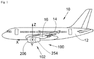
- the figure 1 shows an aircraft 10 which comprises a fuselage 12 on each side of which is fixed a wing 14 which carries at least one bypass turbojet 100 according to the invention.
- the bypass turbojet 100 is attached to the wing 14 by means of a mast 16.
- the longitudinal axis of the bypass turbojet 100 which is parallel to the longitudinal axis of the aircraft 10 and which is oriented positively in the direction of travel of the aircraft is called X.
- the transverse axis of the bypass turbojet 100 which is horizontal when the aircraft is on the ground, and Z is called the vertical axis when the aircraft is on the ground, these three directions X, Y and Z being orthogonal between they.
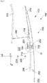
- the figures 2 and 3 show the bypass turbojet 100 which comprises a nacelle 102 and an engine which is housed inside the nacelle 102.
- the engine is represented here by its outer wall 103.
- the longitudinal axis X of the bypass turbojet 100 is also the longitudinal axis of the nacelle 102.
- the nacelle 102 has a fixed structure 205 which includes a fixed cowl 206.
- a duct 202 in which a secondary flow 208 circulates is arranged in the fixed structure 205, between the fixed structure 205, and more generally the nacelle 102, and the engine.
- the nacelle 102 comprises a movable assembly 250 which is movable in translation parallel to a direction of movement generally parallel to the longitudinal axis X relative to the fixed structure 205 and to the fixed cowl 206 between an advanced position and a retracted position.
- the movable assembly 250 In advanced position ( figure. 2 ), the movable assembly 250 is brought closer to the fixed cowl 206 and in the retracted position ( figure 3 ), it is removed from the fixed cover 206 towards the rear so as to open an opening 210 between the duct 202 and the outside.
- the movable assembly 250 comprises a frame 252 which is mounted movable in translation relative to the fixed structure 205 and a movable cover 254 fixed to the rear of the frame 252.
- the movable cover 254 In the advanced position, the movable cover 254 is positioned at the rear. of the fixed cowl 206 and extends it to form the aerodynamic outer surface of the nacelle 102.
- the movable cowl 254 In the retracted position, the movable cowl 254 is moved back relative to the fixed cowl 206 and the opening 210 is thus delimited through the frame at the front by the fixed structure 205 and at the rear by the movable cowl 254.
- the movable assembly 250 comprises, across the frame, cascades 256 integral with the frame 252 and which serve to divert the flow passing through the opening 210 towards the front.
- the cascades 256 have deflection fins.
- the waterfalls 256 are fixed across the frame. In the forward position, the cascades 256 are housed in the fixed structure 205 and in the retracted position, they are positioned across the opening 210.
- the figure 5 shows a front view of the mobile assembly 250.
- the translational guidance of the frame 252 relative to the fixed structure 205 is provided by any suitable means, such as for example slides 502 arranged at 12 o'clock and at 6 o'clock between the fixed structure 205 and the frame 252, etc.
- any suitable means such as for example slides 502 arranged at 12 o'clock and at 6 o'clock between the fixed structure 205 and the frame 252, etc.
- slides 502 arranged at 12 o'clock is shown, but a similar slide can be put in place at 6 o'clock.
- the nacelle 102 comprises at least one reversing door 104.
- Each reversing door 104 allows, depending on its position, to reverse the thrust of the bypass turbojet 100.
- the reversing door 104 has a rear edge which is rotatably mounted on the movable assembly 250, and more particularly on the frame 252, by means of a hinge 251.
- the reversing door 104 is movable between a retracted position and a deployed position for which the reverse thrust has maximum efficiency.
- the reversal door 104 In the retracted position ( figure 2 ), the reversal door 104 is positioned outside the duct 202, and more particularly here it is pressed inside the movable cowl 254 thus constituting an outer surface of the duct 202.
- the gate of inversion 104 opens inwardly and the outer wall 103 positions itself across the vein 202 to deflect at least a portion of the secondary flow 208 outwardly through the opening 210. The free end of the door inversion 104 then approaches the outer wall 103.
- the movement of the reversing door 104 from the retracted position to the deployed position is provided by a drive system 260 which here takes the form of a connecting rod which is mounted articulated between the reversing door 104 and the outer wall. 103.
- a movement of the movable assembly 250 will cause a movement of the reversing door 104 which is retained by the connecting rod 260, which will cause the reversing door 104 to tilt.
- the drive system 260 described above can take other forms, for example a motor mounted at the level of the axis of rotation of the reversing door 104.
- the figure 6 shows a perspective view of half a portion of the movable assembly 250.
- the movable assembly 250 includes at least one threaded rod 402.
- Each threaded rod 402 is parallel to the direction of travel and is secured to frame 252 across the frame. Here, each end of each threaded rod 402 is attached to the frame 252.
- the figure 7 shows a perspective view of a half-part of the fixed structure 205 which here, as for the mobile assembly, is made up of two half-parts each extending over an overall 180 ° but only one of which is shown.
- the figure 4 shows an enlargement of detail IV which corresponds to a section through plan IV of the figure 7 .
- the fixed structure 205 comprises an outer box 702, an inner box 704 and at least one intermediate box 706.
- Each box 702, 704, 706 is a torsion box (“torque box”), that is to say a closed and hollow box. Due to the angular extent of the half-parts of the fixed structure 205 and of the mobile assembly 250, the outer box 702 and the inner box 704 take the form of two half-rings concentric around the longitudinal axis X.
- the outer box 702 takes the form of a box of revolution around the longitudinal axis X and the inner box 704 takes the form of a box of revolution around the longitudinal axis X and inside the outer box 702
- the outer box 702 extends over the outside of the fixed structure 205.
- Each intermediate box 706 extends generally radially with respect to the longitudinal axis X and it is fixed to the inner box 704 and to the outer box 702, for example by welding or bolting, or else each intermediate box 706 may be an integral part of a integrated composite part made up of an inner box 704, an outer box 702 and intermediate boxes 706.
- Such a structure based on a torsion box is particularly light and rigid.
- the fixed structure 205 For each threaded rod 402, the fixed structure 205 comprises a motorized nut 708 fixed to at least one box among the outer box 702, the inner box 704 or an intermediate box 706 and with which the threaded rod 402 meshes. Each motorized nut 708 is arranged here facing an intermediate box 706.
- the motorized nut 708 has a ball nut which meshes with the threaded rod 402 and an actuator which rotates the ball nut and which is attached to at least one of the outer casing 702, the inner casing 704 or a casing. intermediate 706.
- the actuator is fixed to the outer casing 702 and to the intermediate casing 706. The forces which pass through the actuator are thus taken up by the casings 702, 704, 706 to which it is fixed.
- boxes 702, 704 and 706 allows a reinforcement of the fixed structure 205 and to integrate the actuator therein and thus makes it possible to reduce the thickness of the movable cowl 254 and thus to have external lines of the nacelle 102 thinner and therefore exhibiting better aerodynamic performance.
- the fixed structure 205 has between the outer casing 702 and the inner casing 704, a slot 710 in which a cascade 256 is arranged. This slot 710 allows the movement of the cascade 256 between the advanced position and the retracted position, and vice versa. Thus for each cascade 256, the fixed structure 205 has a slot 710 in which said cascade 256 is disposed, and each slot 710 is delimited between the outer casing 702 and the inner casing 704.
- each slot 710 is angularly delimited by two successive intermediate boxes 706.
- the outer casing 702 carries a support element 404 which has an outer bearing face 406 oriented towards the outside and against which the fixed cover 206 rests.
- the outer bearing face 406 is positioned inside of the fixed cover 206.
- the fixed cowl 206 undergoes deformations which move it relative to the outer bearing face 406.
- a strip of Teflon® is fixed between them, that is, that is to say on the outer bearing face 406 or inside the fixed cover 206.
- the latter carries a seal 408 which is positioned between the movable cover 254 and the outer casing 702 in the advanced position.
Landscapes
- Engineering & Computer Science (AREA)
- Mechanical Engineering (AREA)
- General Engineering & Computer Science (AREA)
- Chemical & Material Sciences (AREA)
- Combustion & Propulsion (AREA)
- Aviation & Aerospace Engineering (AREA)
- Structures Of Non-Positive Displacement Pumps (AREA)
- Wind Motors (AREA)
Abstract
Description
- La présente invention concerne une nacelle d'un turboréacteur double flux qui comporte un ensemble mobile et une structure fixe renforcée, un turboréacteur double flux comportant un moteur et une telle nacelle, ainsi qu'un aéronef comportant au moins un tel turboréacteur double flux.
- Un aéronef comporte un fuselage de chaque côté duquel est fixée une aile. Sous chaque aile est suspendu au moins un turboréacteur double flux. Chaque turboréacteur double flux est fixé sous l'aile par l'intermédiaire d'un mât qui est fixé entre la structure de l'aile et la structure du turboréacteur double flux.
- Le turboréacteur double flux comporte un moteur et une nacelle qui est fixée autour du moteur. Le turboréacteur comporte également une soufflante qui est montée à l'avant du moteur et l'air entraîné par la soufflante se divise en un flux primaire qui traverse le moteur et un flux secondaire qui traverse une veine secondaire délimitée entre le moteur et la nacelle.
- La nacelle comporte un carter de soufflante qui s'étend autour de la soufflante et qui est fixe.
- La nacelle comporte également un ensemble mobile en translation qui porte des portes d'inversion d'un système d'inversion de poussée qui permet de dévier le flux secondaire vers l'extérieur de la nacelle et vers l'avant.
- L'ensemble mobile est disposé à l'arrière du carter de soufflante et il est mobile entre une position avancée et une position reculée.
- En position avancée, l'ensemble mobile est rapproché du carter de soufflante pour former une surface extérieure aérodynamique de la nacelle et une surface externe dans la paroi de la veine secondaire. En position reculée, l'ensemble mobile est éloigné du carter de soufflante pour libérer une ouverture entre le carter de soufflante et l'ensemble mobile, où ladite ouverture ouvre un passage entre la veine secondaire et l'extérieur.
- L'ensemble mobile comporte un châssis monté coulissant sur une structure fixe de la nacelle et des capots extérieurs qui forment la surface extérieure de la nacelle et des parois intérieures qui forment la surface extérieure de la veine secondaire.
- L'ensemble mobile comporte également des actionneurs, comme par exemple des vérins qui sont fixés entre le châssis de l'ensemble mobile et la structure fixe et qui sont commandés pour déplacer le châssis dans un sens ou dans l'autre.
- Chaque porte d'inversion est mobile en rotation sur le châssis de l'ensemble mobile entre une position escamotée et une position déployée. En position escamotée, la porte d'inversion est en dehors de la veine secondaire et ne fait pas obstacle au flux secondaire, et en position déployée, la porte d'inversion est en travers de la veine secondaire et fait obstacle au flux secondaire pour le dévier vers l'ouverture.
- Les efforts générés par les actionneurs sont relativement importants, et il est nécessaire de prévoir des structures lourdes pouvant supporter de tels efforts. Des architectures plus légères ont été développées et sont, par exemple, décrites dans les documents
US2015/354499 etUS3500646 . - Un objet de la présente invention est de proposer une nacelle d'un turboréacteur double flux qui comporte un ensemble mobile et une structure fixe renforcée et plus légère, d'une conception alternative de celles décrites dans les deux documents susmentionnés.
- A cet effet, est proposée une nacelle pour un turboréacteur double flux tel que revendiquée dans la revendication 1.
- Une telle architecture intégrant des caissons de torsion sur lesquels sont fixés les actionneurs de l'ensemble mobile permet une reprise des efforts générés par lesdits actionneurs avec des lignes externes de la nacelle plus fines et présentant donc de meilleures performances aérodynamiques.
- Les caractéristiques de l'invention mentionnées ci-dessus, ainsi que d'autres, apparaîtront plus clairement à la lecture de la description suivante d'un exemple de réalisation, ladite description étant faite en relation avec les dessins joints, parmi lesquels :
- La
figure 1 est une vue de côté d'un aéronef comportant une nacelle selon l'invention, - La
figure 2 est une vue en coupe par un plan vertical de la nacelle en position avancée et en position escamotée de la porte d'inversion, - La
figure 3 est une vue en coupe par un plan vertical de la nacelle en position reculée et en position déployée de la porte d'inversion, - La
figure 4 est un agrandissement du détail IV de lafigure 2 , - La
figure 5 est une vue de face de la nacelle, - La
figure 6 est une vue en perspective d'un ensemble mobile de la nacelle selon l'invention, et - La
figure 7 est une vue en perspective d'une structure fixe selon l'invention. - Dans la description qui suit, les termes relatifs à une position sont pris en référence à un aéronef en position d'avancement comme il est représenté sur la
figure 1 . - La
figure 1 montre un aéronef 10 qui comporte un fuselage 12 de chaque côté duquel est fixée une aile 14 qui porte au moins un turboréacteur double flux 100 selon l'invention. La fixation du turboréacteur double flux 100 sous l'aile 14 s'effectue par l'intermédiaire d'un mât 16. - Dans la description qui suit, et par convention, on appelle X l'axe longitudinal du turboréacteur double flux 100 qui est parallèle à l'axe longitudinal de l'aéronef 10 et qui est orienté positivement dans le sens d'avancement de l'aéronef 10, on appelle Y l'axe transversal du turboréacteur double flux 100 qui est horizontal lorsque l'aéronef est au sol, et Z l'axe vertical lorsque l'aéronef est au sol, ces trois directions X, Y et Z étant orthogonales entre elles.
- Les
figures 2 et3 montrent le turboréacteur double flux 100 qui comporte une nacelle 102 et un moteur qui est logé à l'intérieur de la nacelle 102. Le moteur est matérialisé ici par sa paroi extérieure 103. L'axe longitudinal X du turboréacteur double flux 100 est également l'axe longitudinal de la nacelle 102. - La nacelle 102 présente une structure fixe 205 qui comporte un capot fixe 206.
- Une veine 202 dans laquelle circule un flux secondaire 208 est agencée dans la structure fixe 205, entre la structure fixe 205, et plus généralement la nacelle 102, et le moteur.
- La nacelle 102 comporte un ensemble mobile 250 qui est mobile en translation parallèlement à une direction de déplacement globalement parallèle à l'axe longitudinal X par rapport à la structure fixe 205 et au capot fixe 206 entre une position avancée et une position reculée.
- En position avancée (
figure. 2 ), l'ensemble mobile 250 est rapproché du capot fixe 206 et en position reculée (figure 3 ), il est éloigné du capot fixe 206 vers l'arrière de manière à ouvrir une ouverture 210 entre la veine 202 et l'extérieur. - L'ensemble mobile 250 comporte un châssis 252 qui est monté mobile en translation par rapport à la structure fixe 205 et un capot mobile 254 fixé à l'arrière du châssis 252. En position avancée, le capot mobile 254 se positionne à l'arrière du capot fixe 206 et le prolonge pour former la surface extérieure aérodynamique de la nacelle 102. En position reculée, le capot mobile 254 est reculé par rapport au capot fixe 206 et l'ouverture 210 est ainsi délimitée à travers le cadre à l'avant par la structure fixe 205 et à l'arrière par le capot mobile 254.
- Dans le mode de réalisation de l'invention présenté ici, l'ensemble mobile 250 comporte, en travers du cadre, des cascades 256 solidaires du châssis 252 et qui servent à dévier le flux traversant l'ouverture 210 vers l'avant. A cette fin, les cascades 256 présentent des ailettes de déviation. Les cascades 256 sont fixées en travers du cadre. En position avancée, les cascades 256 logent dans la structure fixe 205 et en position reculée, elles se positionnent en travers de l'ouverture 210.
- La
figure 5 montre une vue de face de l'ensemble mobile 250. - Le guidage en translation du châssis 252 par rapport à la structure fixe 205 est assuré par tous moyens appropriés, comme par exemple des glissières 502 disposées à 12 heures et à 6 heures entre la structure fixe 205 et le châssis 252, etc. Sur la
figure 5 , seule la glissière 502 disposée à 12 heures est représentée, mais une glissière similaire peut être mise en place à 6 heures. - Dans le mode de réalisation de l'invention présenté ici, la nacelle 102 comporte au moins une porte d'inversion 104. En particulier, il peut y avoir deux portes d'inversion 104 disposées l'une en face de l'autre, ou plus de deux portes d'inversion 104 réparties régulièrement sur la périphérie de la nacelle 102. Chaque porte d'inversion 104 permet selon sa position d'inverser la poussée du turboréacteur double flux 100.
- Dans la description qui suit, l'invention est plus particulièrement décrite pour une porte d'inversion 104, mais elle s'applique de la même manière pour chaque porte d'inversion 104 lorsqu'il y en a plusieurs.
- La porte d'inversion 104 présente un bord arrière qui est monté libre en rotation sur l'ensemble mobile 250, et plus particulièrement sur le châssis 252, par l'intermédiaire d'une articulation 251. La porte d'inversion 104 est mobile entre une position escamotée et une position déployée pour laquelle l'inversion de poussée a une efficacité maximale. En position escamotée (
figure 2 ), la porte d'inversion 104 se positionne en dehors de la veine 202, et plus particulièrement ici elle se plaque à l'intérieur du capot mobile 254 constituant ainsi une surface extérieure de la veine 202. En position déployée, la porte d'inversion 104 s'ouvre vers l'intérieur et la paroi extérieure 103 se positionne en travers de la veine 202 pour dévier au moins une partie du flux secondaire 208 vers l'extérieur à travers l'ouverture 210. L'extrémité libre de la porte d'inversion 104 se rapproche alors de la paroi extérieure 103. - Le déplacement de la porte d'inversion 104 de la position escamotée à la position déployée est assuré par un système d'entraînement 260 qui prend ici la forme d'une bielle qui est montée articulée entre la porte d'inversion 104 et la paroi extérieure 103. Ainsi, un déplacement de l'ensemble mobile 250 va entraîner un déplacement de la porte d'inversion 104 qui est retenue par la bielle 260 ce qui va entraîner un basculement de la porte d'inversion 104.
- Le système d'entraînement 260 décrit ci-dessus peut prendre d'autres formes comme par exemple un moteur monté au niveau de l'axe de rotation de la porte d'inversion 104.
- La
figure 6 montre une vue en perspective d'une demi-partie de l'ensemble mobile 250. L'ensemble mobile 250 comporte au moins une tige filetée 402. Dans le mode de réalisation de l'invention présenté ici, il y a trois tiges filetées 402 et chacune est disposée entre deux cascades 256, mais le nombre peut varier en fonction de l'étendue angulaire de l'ensemble mobile 250, qui ici est constitué de deux demi-parties s'étendant chacune sur globalement 180° mais dont une seule est représentée et qui chacune comporte donc trois tiges filetées 402. - Chaque tige filetée 402 est parallèle à la direction de déplacement et est fixée au châssis 252 en travers du cadre. Ici, chaque extrémité de chaque tige filetée 402 est fixée au châssis 252.
- La
figure 7 montre une vue en perspective d'une demi-partie de la structure fixe 205 qui ici, comme pour l'ensemble mobile, est constituée de deux demi-parties s'étendant chacune sur globalement 180° mais dont une seule est représentée. Lafigure 4 montre un agrandissement du détail IV qui correspond à une coupe par le plan IV de lafigure 7 . - La description qui suit s'appuie sur une demi-partie de la structure fixe 205, mais elle s'applique de la même manière à l'autre demi-partie.
- La structure fixe 205 comporte un caisson extérieur 702, un caisson intérieur 704 et au moins un caisson intermédiaire 706.
- Chaque caisson 702, 704, 706 est un caisson de torsion (« torque box » en langue anglo-saxonne), c'est-à-dire un caisson fermé et creux. Du fait de l'étendue angulaire des demi-parties de la structure fixe 205 et de l'ensemble mobile 250, le caisson extérieur 702 et le caisson intérieur 704 prennent la forme de deux demi-anneaux concentriques autour de l'axe longitudinal X.
- Le caisson extérieur 702 prend la forme d'un caisson de révolution autour de l'axe longitudinal X et le caisson intérieur 704 prend la forme d'un caisson de révolution autour de l'axe longitudinal X et à l'intérieur du caisson extérieur 702. Le caisson extérieur 702 s'étend sur l'extérieur de la structure fixe 205.
- Chaque caisson intermédiaire 706 s'étend globalement radialement par rapport à l'axe longitudinal X et il est fixé au caisson intérieur 704 et au caisson extérieur 702, par exemple par soudure ou boulonnage ou bien chaque caisson intermédiaire 706 peut faire partie intégrante d'une pièce composite intégrée constituée d'un caisson intérieur 704, d'un caisson extérieur 702 et de caissons intermédiaires 706.
- Il y a ici six caissons intermédiaires 706 régulièrement répartis angulairement.
- Une telle structure à base de caisson de torsion est particulièrement légère et rigide.
- Pour chaque tige filetée 402, la structure fixe 205 comporte un écrou motorisé 708 fixé à au moins un caisson parmi le caisson extérieur 702, le caisson intérieur 704 ou un caisson intermédiaire 706 et avec lequel la tige filetée 402 engrène. Chaque écrou motorisé 708 est disposé ici en regard d'un caisson intermédiaire 706.
- L'écrou motorisé 708 comporte un écrou à billes qui engrène avec la tige filetée 402 et un actionneur qui fait tourner l'écrou à billes et qui est fixé à au moins un caisson parmi le caisson extérieur 702, le caisson intérieur 704 ou un caisson intermédiaire 706. Dans le mode de réalisation de l'invention présenté ici, l'actionneur est fixé au caisson extérieur 702 et au caisson intermédiaire 706. Les efforts qui transitent par l'actionneur sont ainsi repris par les caissons 702, 704, 706 auquel il est fixé.
- L'utilisation des caissons 702, 704 et 706 permet un renfort de la structure fixe 205 et d'y intégrer l'actionneur et ainsi permet de diminuer l'épaisseur du capot mobile 254 et d'avoir ainsi des lignes externes de la nacelle 102 plus fines et présentant donc de meilleures performances aérodynamiques.
- La structure fixe 205 présente entre le caisson extérieur 702 et le caisson intérieur 704, une fente 710 dans laquelle une cascade 256 est disposée. Cette fente 710 permet le déplacement de la cascade 256 entre la position avancée et la position reculée, et inversement. Ainsi pour chaque cascade 256, la structure fixe 205 présente une fente 710 dans laquelle ladite cascade 256 est disposée, et chaque fente 710 est délimitée entre le caisson extérieur 702 et le caisson intérieur 704.
- Dans le mode de réalisation de l'invention présenté ici, chaque fente 710 est angulairement délimitée par deux caissons intermédiaires 706 successifs.
- Comme le montre la
figure 4 , le caisson extérieur 702 porte un élément d'appui 404 qui présente une face extérieure d'appui 406 orientée vers l'extérieur et contre laquelle s'appuie le capot fixe 206. La face extérieure d'appui 406 se positionne à l'intérieur du capot fixe 206. - Lors du fonctionnement du turboréacteur 100, le capot fixe 206 subit des déformations qui le déplacent par rapport à la face extérieure d'appui 406. Pour limiter les frottements lors de ces déplacements, une bande de Téflon ® est fixée entre eux, c'est-à-dire sur la face extérieure d'appui 406 ou à l'intérieur du capot fixe 206.
- Pour améliorer l'étanchéité entre le capot mobile 254 et le caisson extérieur 702, celui-ci porte un joint 408 qui se positionne entre le capot mobile 254 et le caisson extérieur 702 en position avancée.
Claims (8)
- Nacelle (102) pour un turboréacteur double flux (100), ladite nacelle (102) ayant un axe longitudinal et comportant :- une structure fixe (205) comportant un capot fixe (206) et dans laquelle est agencée une veine (202) dans laquelle circule un flux secondaire (208),- un ensemble mobile (250) comportant un châssis (252) formant un cadre et un capot mobile (254) fixé à l'arrière du châssis (252), où le châssis (252) est mobile par rapport à la structure fixe (205) en translation parallèlement à une direction de déplacement entre une position avancée dans laquelle le capot mobile (254) se positionne à l'arrière du capot fixe (206) et le prolonge, et une position reculée dans laquelle le capot mobile (254) est reculé par rapport au capot fixe (206) de manière à ouvrir une ouverture (210) à travers le cadre entre la veine (202) et l'extérieur,où l'ensemble mobile (250) comporte au moins une tige filetée (402), chacune étant parallèle à la direction de déplacement et fixée au châssis (252) en travers du cadre,
où pour chaque tige filetée (402), la structure fixe (205) comporte un écrou motorisé (708) comportant un écrou à billes qui engrène avec la tige filetée (402), et un actionneur qui fait tourner l'écrou à billes
caractérisé en ce que la structure fixe (205) comporte un caisson extérieur (702), un caisson intérieur (704) et au moins un caisson intermédiaire (706), où le caisson extérieur (702) prend la forme d'un caisson de révolution autour de l'axe longitudinal, où le caisson intérieur (704) prend la forme d'un caisson de révolution autour de l'axe longitudinal et à l'intérieur du caisson extérieur (702), et où chaque caisson intermédiaire (706) s'étend globalement radialement par rapport à l'axe longitudinal et est fixé au caisson intérieur (704) et au caisson extérieur (702), et en ce que l'actionneur est fixé à au moins un caisson parmi le caisson extérieur (702), le caisson intérieur (704) ou un caisson intermédiaire (706). - Nacelle (102) selon la revendication 1, caractérisée en ce qu'elle comporte des cascades (256) solidaires du châssis (252) de l'ensemble mobile (250) et fixées en travers du cadre, en ce que, pour chaque cascade (256), la structure fixe (205) présente une fente (710) dans laquelle ladite cascade (256) est disposée, et en ce que chaque fente (710) est délimitée entre le caisson extérieur (702) et le caisson intérieur (704).
- Nacelle (102) selon la revendication 2, caractérisée en ce que chaque fente (710) est angulairement délimitée par deux caissons intermédiaires (706) successifs.
- Nacelle (102) selon l'une des revendications précédentes, caractérisée en ce que le caisson extérieur (702) porte un élément d'appui (404) qui présente une face extérieure d'appui (406) orientée vers l'extérieur et contre laquelle s'appuie le capot fixe (206).
- Nacelle (102) selon la revendication 4, caractérisée en ce qu'une bande de téflon ® est fixée soit sur la face extérieure d'appui (406), soit à l'intérieur du capot fixe (206).
- Nacelle (102) selon l'une des revendications précédentes, caractérisée en ce que le caisson extérieur (702) porte un joint (408) qui se positionne entre le capot mobile (254) et le caisson extérieur (702) en position avancée.
- Turboréacteur double flux (100) comportant un moteur et une nacelle (102) selon l'une des revendications précédentes, où la veine (202) est délimitée entre le moteur et la nacelle (102).
- Aéronef (10) comportant un turboréacteur double flux (100) selon la revendication précédente.
Applications Claiming Priority (1)
| Application Number | Priority Date | Filing Date | Title |
|---|---|---|---|
| FR1900534A FR3091855A1 (fr) | 2019-01-22 | 2019-01-22 | NACELLE D’UN TURBOREACTEUR COMPORTANT UN ensemble mobile ET UNe structure fixe renforcee |
Publications (2)
| Publication Number | Publication Date |
|---|---|
| EP3693592A1 true EP3693592A1 (fr) | 2020-08-12 |
| EP3693592B1 EP3693592B1 (fr) | 2021-04-14 |
Family
ID=66867404
Family Applications (1)
| Application Number | Title | Priority Date | Filing Date |
|---|---|---|---|
| EP20151146.6A Active EP3693592B1 (fr) | 2019-01-22 | 2020-01-10 | Nacelle d'un turboreacteur comportant un ensemble mobile et une structure fixe renforcee |
Country Status (4)
| Country | Link |
|---|---|
| US (1) | US11293376B2 (fr) |
| EP (1) | EP3693592B1 (fr) |
| CN (1) | CN111452983B (fr) |
| FR (1) | FR3091855A1 (fr) |
Citations (11)
| Publication number | Priority date | Publication date | Assignee | Title |
|---|---|---|---|---|
| US3262270A (en) * | 1965-06-07 | 1966-07-26 | Gen Electric | Thrust reverser |
| US3500646A (en) | 1968-04-19 | 1970-03-17 | Rohr Corp | Thrust reverser |
| US5778659A (en) * | 1994-10-20 | 1998-07-14 | United Technologies Corporation | Variable area fan exhaust nozzle having mechanically separate sleeve and thrust reverser actuation systems |
| ES2391342A1 (es) * | 2009-06-30 | 2012-11-23 | General Electric Company | Sistema y procedimiento para montar un inversor de empuje para un sistema de propulsión de turbina de gas. |
| WO2015019007A1 (fr) * | 2013-08-07 | 2015-02-12 | Aircelle | Dispositif d'inversion de poussée intégré et nacelle de moteur d'aéronef ainsi équipée |
| US20150308379A1 (en) * | 2014-04-24 | 2015-10-29 | Rohr, Inc. | Integral cascade-variable area fan nozzle system and method |
| US20150354499A1 (en) | 2011-08-05 | 2015-12-10 | Aircelle | Turbojet engine nacelle having a variable nozzle |
| US20160169157A1 (en) * | 2014-12-15 | 2016-06-16 | United Technologies Corporation | Gas turbine engine and thrust reverser assembly therefore |
| US20170167440A1 (en) * | 2015-12-14 | 2017-06-15 | Rohr, Inc. | Thrust reverser system with translating elements |
| US20170321632A1 (en) * | 2016-05-09 | 2017-11-09 | Mra Systems, Inc. | Gas turbine engine with thrust reverser assembly and method of operating |
| FR3064308A1 (fr) * | 2017-03-23 | 2018-09-28 | Airbus Operations | Turboreacteur comportant une nacelle equipee de volets inverseurs |
Family Cites Families (9)
| Publication number | Priority date | Publication date | Assignee | Title |
|---|---|---|---|---|
| GB1421153A (en) * | 1972-03-25 | 1976-01-14 | Rolls Royce | Propulsion nozzle for ducted fan gas turbine jet propulsion engines |
| US4005822A (en) * | 1975-12-22 | 1977-02-01 | Rohr Industries, Inc. | Fan duct thrust reverser |
| US4216909A (en) * | 1977-10-04 | 1980-08-12 | Rolls-Royce Limited | Brake mechanism for rotary parts |
| GB2154291B (en) * | 1984-02-14 | 1987-08-12 | Rolls Royce | Anti rotation device |
| GB9825651D0 (en) * | 1998-11-23 | 1999-01-13 | Lucas Ind Plc | Actuator |
| FR2914956A1 (fr) * | 2007-04-12 | 2008-10-17 | Aircelle Sa | Nacelle pour turboreacteur equipee d'un systeme d'inversion de poussee a porte |
| FR3062371B1 (fr) * | 2017-01-31 | 2019-03-29 | Airbus | Nacelle d'un turboreacteur comportant un volet inverseur |
| FR3068394B1 (fr) * | 2017-06-29 | 2019-07-19 | Airbus Operations | Turboreacteur comportant une nacelle equipee de volets inverseurs |
| US10704497B2 (en) * | 2018-01-10 | 2020-07-07 | Woodward, Inc. | Thrust reverser velocity control valve |
-
2019
- 2019-01-22 FR FR1900534A patent/FR3091855A1/fr not_active Ceased
-
2020
- 2020-01-10 EP EP20151146.6A patent/EP3693592B1/fr active Active
- 2020-01-17 US US16/745,627 patent/US11293376B2/en active Active
- 2020-01-20 CN CN202010064976.0A patent/CN111452983B/zh active Active
Patent Citations (11)
| Publication number | Priority date | Publication date | Assignee | Title |
|---|---|---|---|---|
| US3262270A (en) * | 1965-06-07 | 1966-07-26 | Gen Electric | Thrust reverser |
| US3500646A (en) | 1968-04-19 | 1970-03-17 | Rohr Corp | Thrust reverser |
| US5778659A (en) * | 1994-10-20 | 1998-07-14 | United Technologies Corporation | Variable area fan exhaust nozzle having mechanically separate sleeve and thrust reverser actuation systems |
| ES2391342A1 (es) * | 2009-06-30 | 2012-11-23 | General Electric Company | Sistema y procedimiento para montar un inversor de empuje para un sistema de propulsión de turbina de gas. |
| US20150354499A1 (en) | 2011-08-05 | 2015-12-10 | Aircelle | Turbojet engine nacelle having a variable nozzle |
| WO2015019007A1 (fr) * | 2013-08-07 | 2015-02-12 | Aircelle | Dispositif d'inversion de poussée intégré et nacelle de moteur d'aéronef ainsi équipée |
| US20150308379A1 (en) * | 2014-04-24 | 2015-10-29 | Rohr, Inc. | Integral cascade-variable area fan nozzle system and method |
| US20160169157A1 (en) * | 2014-12-15 | 2016-06-16 | United Technologies Corporation | Gas turbine engine and thrust reverser assembly therefore |
| US20170167440A1 (en) * | 2015-12-14 | 2017-06-15 | Rohr, Inc. | Thrust reverser system with translating elements |
| US20170321632A1 (en) * | 2016-05-09 | 2017-11-09 | Mra Systems, Inc. | Gas turbine engine with thrust reverser assembly and method of operating |
| FR3064308A1 (fr) * | 2017-03-23 | 2018-09-28 | Airbus Operations | Turboreacteur comportant une nacelle equipee de volets inverseurs |
Also Published As
| Publication number | Publication date |
|---|---|
| US20200231296A1 (en) | 2020-07-23 |
| US11293376B2 (en) | 2022-04-05 |
| CN111452983B (zh) | 2023-04-04 |
| FR3091855A1 (fr) | 2020-07-24 |
| CN111452983A (zh) | 2020-07-28 |
| EP3693592B1 (fr) | 2021-04-14 |
Similar Documents
| Publication | Publication Date | Title |
|---|---|---|
| EP0301939B1 (fr) | Inverseur de poussée de turboréacteur muni d'un déflecteur mobile de porte | |
| EP0822327B1 (fr) | Inverseur de poussée de turboréacteur à portes formant écopes | |
| EP0851111B1 (fr) | Inverseur de poussée de turboréacteur à double flux à coquille aval | |
| CA2191179C (fr) | Inverseur de poussee de turboreacteur a portes a panneau arriere articule | |
| EP3421771B1 (fr) | Turboréacteur comportant une nacelle équipée de volets inverseurs | |
| EP3309380B1 (fr) | Nacelle d'un turboréacteur comportant un volet inverseur | |
| CA2223564A1 (fr) | Inverseur de poussee de turboreacteur a portes comportant des aubes deflectrices associees a la structure fixe | |
| CA2204589C (fr) | Inverseur de poussee de turboreacteur a portes munies d'aubes deflectrices | |
| EP3845754B1 (fr) | Turboréacteur double flux comportant un système d'obturation de la veine du flux secondaire comportant un voile | |
| EP0882881B1 (fr) | Inverseur de poussée de turboréacteur à portes munies d'un becquet mobile à entrainement optimisé | |
| FR2651278A1 (fr) | Inverseur a grilles sans capot coulissant pour turboreacteur. | |
| FR3064308A1 (fr) | Turboreacteur comportant une nacelle equipee de volets inverseurs | |
| EP0761957A1 (fr) | Inverseur de poussée de turboréacteur à portes associées à un panneau amont formant écope | |
| FR2764339A1 (fr) | Inverseur de poussee de turboreacteur a portes formant ecopes associees a une casquette amont mobile | |
| EP3726037A1 (fr) | Turboréacteur double flux comportant une série de lames rotatives pour obturer la veine du flux secondaire | |
| EP0807752B1 (fr) | Inverseur de poussée de turboréacteur à portes associées à un panneau amont | |
| EP3495651B1 (fr) | Grille pour la formation d'un flux d'inversion d'un turboréacteur d'aéronef | |
| EP0821151A1 (fr) | Inverseur de poussée de turboréacteur à portes comportant un panneau coulissant | |
| EP3550134B1 (fr) | Turboréacteur comportant une nacelle équipée d'un système inverseur comportant un capot articulé | |
| EP0835999A1 (fr) | Inverseur de poussée à portes à installation de vérin de commande optimisée | |
| EP3693592B1 (fr) | Nacelle d'un turboreacteur comportant un ensemble mobile et une structure fixe renforcee | |
| EP3978730B1 (fr) | Turboréacteur double flux d'un aéronef comportant un capot articulé en rotation et un système de déploiement dudit capot | |
| FR2927956A1 (fr) | Inverseur de poussee pour nacelle de turboreacteur a double flux | |
| EP3530571A1 (fr) | Nacelle equipee d'un systeme inverseur comportant des portes et des systemes anti-vibration des portes en position stockee | |
| FR3007799A1 (fr) | Inverseur a doubles grilles sans bielles dans la veine |
Legal Events
| Date | Code | Title | Description |
|---|---|---|---|
| PUAI | Public reference made under article 153(3) epc to a published international application that has entered the european phase |
Free format text: ORIGINAL CODE: 0009012 |
|
| STAA | Information on the status of an ep patent application or granted ep patent |
Free format text: STATUS: REQUEST FOR EXAMINATION WAS MADE |
|
| 17P | Request for examination filed |
Effective date: 20200110 |
|
| AK | Designated contracting states |
Kind code of ref document: A1 Designated state(s): AL AT BE BG CH CY CZ DE DK EE ES FI FR GB GR HR HU IE IS IT LI LT LU LV MC MK MT NL NO PL PT RO RS SE SI SK SM TR |
|
| AX | Request for extension of the european patent |
Extension state: BA ME |
|
| GRAP | Despatch of communication of intention to grant a patent |
Free format text: ORIGINAL CODE: EPIDOSNIGR1 |
|
| STAA | Information on the status of an ep patent application or granted ep patent |
Free format text: STATUS: GRANT OF PATENT IS INTENDED |
|
| INTG | Intention to grant announced |
Effective date: 20210120 |
|
| GRAS | Grant fee paid |
Free format text: ORIGINAL CODE: EPIDOSNIGR3 |
|
| GRAA | (expected) grant |
Free format text: ORIGINAL CODE: 0009210 |
|
| STAA | Information on the status of an ep patent application or granted ep patent |
Free format text: STATUS: THE PATENT HAS BEEN GRANTED |
|
| RBV | Designated contracting states (corrected) |
Designated state(s): AL AT BE BG CH CY CZ DE DK EE ES FI FR GB GR HR HU IE IS IT LI LT LU LV MC MK MT NL NO PL PT RO RS SE SI SK SM TR |
|
| AK | Designated contracting states |
Kind code of ref document: B1 Designated state(s): AL AT BE BG CH CY CZ DE DK EE ES FI FR GB GR HR HU IE IS IT LI LT LU LV MC MK MT NL NO PL PT RO RS SE SI SK SM TR |
|
| REG | Reference to a national code |
Ref country code: GB Ref legal event code: FG4D Free format text: NOT ENGLISH |
|
| REG | Reference to a national code |
Ref country code: CH Ref legal event code: EP |
|
| REG | Reference to a national code |
Ref country code: DE Ref legal event code: R096 Ref document number: 602020000054 Country of ref document: DE |
|
| REG | Reference to a national code |
Ref country code: IE Ref legal event code: FG4D Free format text: LANGUAGE OF EP DOCUMENT: FRENCH |
|
| REG | Reference to a national code |
Ref country code: AT Ref legal event code: REF Ref document number: 1382594 Country of ref document: AT Kind code of ref document: T Effective date: 20210515 |
|
| REG | Reference to a national code |
Ref country code: LT Ref legal event code: MG9D |
|
| REG | Reference to a national code |
Ref country code: AT Ref legal event code: MK05 Ref document number: 1382594 Country of ref document: AT Kind code of ref document: T Effective date: 20210414 |
|
| REG | Reference to a national code |
Ref country code: NL Ref legal event code: MP Effective date: 20210414 |
|
| PG25 | Lapsed in a contracting state [announced via postgrant information from national office to epo] |
Ref country code: LT Free format text: LAPSE BECAUSE OF FAILURE TO SUBMIT A TRANSLATION OF THE DESCRIPTION OR TO PAY THE FEE WITHIN THE PRESCRIBED TIME-LIMIT Effective date: 20210414 Ref country code: HR Free format text: LAPSE BECAUSE OF FAILURE TO SUBMIT A TRANSLATION OF THE DESCRIPTION OR TO PAY THE FEE WITHIN THE PRESCRIBED TIME-LIMIT Effective date: 20210414 Ref country code: FI Free format text: LAPSE BECAUSE OF FAILURE TO SUBMIT A TRANSLATION OF THE DESCRIPTION OR TO PAY THE FEE WITHIN THE PRESCRIBED TIME-LIMIT Effective date: 20210414 Ref country code: AT Free format text: LAPSE BECAUSE OF FAILURE TO SUBMIT A TRANSLATION OF THE DESCRIPTION OR TO PAY THE FEE WITHIN THE PRESCRIBED TIME-LIMIT Effective date: 20210414 Ref country code: BG Free format text: LAPSE BECAUSE OF FAILURE TO SUBMIT A TRANSLATION OF THE DESCRIPTION OR TO PAY THE FEE WITHIN THE PRESCRIBED TIME-LIMIT Effective date: 20210714 Ref country code: NL Free format text: LAPSE BECAUSE OF FAILURE TO SUBMIT A TRANSLATION OF THE DESCRIPTION OR TO PAY THE FEE WITHIN THE PRESCRIBED TIME-LIMIT Effective date: 20210414 |
|
| PG25 | Lapsed in a contracting state [announced via postgrant information from national office to epo] |
Ref country code: LV Free format text: LAPSE BECAUSE OF FAILURE TO SUBMIT A TRANSLATION OF THE DESCRIPTION OR TO PAY THE FEE WITHIN THE PRESCRIBED TIME-LIMIT Effective date: 20210414 Ref country code: NO Free format text: LAPSE BECAUSE OF FAILURE TO SUBMIT A TRANSLATION OF THE DESCRIPTION OR TO PAY THE FEE WITHIN THE PRESCRIBED TIME-LIMIT Effective date: 20210714 Ref country code: PL Free format text: LAPSE BECAUSE OF FAILURE TO SUBMIT A TRANSLATION OF THE DESCRIPTION OR TO PAY THE FEE WITHIN THE PRESCRIBED TIME-LIMIT Effective date: 20210414 Ref country code: PT Free format text: LAPSE BECAUSE OF FAILURE TO SUBMIT A TRANSLATION OF THE DESCRIPTION OR TO PAY THE FEE WITHIN THE PRESCRIBED TIME-LIMIT Effective date: 20210816 Ref country code: RS Free format text: LAPSE BECAUSE OF FAILURE TO SUBMIT A TRANSLATION OF THE DESCRIPTION OR TO PAY THE FEE WITHIN THE PRESCRIBED TIME-LIMIT Effective date: 20210414 Ref country code: SE Free format text: LAPSE BECAUSE OF FAILURE TO SUBMIT A TRANSLATION OF THE DESCRIPTION OR TO PAY THE FEE WITHIN THE PRESCRIBED TIME-LIMIT Effective date: 20210414 Ref country code: IS Free format text: LAPSE BECAUSE OF FAILURE TO SUBMIT A TRANSLATION OF THE DESCRIPTION OR TO PAY THE FEE WITHIN THE PRESCRIBED TIME-LIMIT Effective date: 20210814 Ref country code: GR Free format text: LAPSE BECAUSE OF FAILURE TO SUBMIT A TRANSLATION OF THE DESCRIPTION OR TO PAY THE FEE WITHIN THE PRESCRIBED TIME-LIMIT Effective date: 20210715 |
|
| REG | Reference to a national code |
Ref country code: DE Ref legal event code: R097 Ref document number: 602020000054 Country of ref document: DE |
|
| PG25 | Lapsed in a contracting state [announced via postgrant information from national office to epo] |
Ref country code: SK Free format text: LAPSE BECAUSE OF FAILURE TO SUBMIT A TRANSLATION OF THE DESCRIPTION OR TO PAY THE FEE WITHIN THE PRESCRIBED TIME-LIMIT Effective date: 20210414 Ref country code: ES Free format text: LAPSE BECAUSE OF FAILURE TO SUBMIT A TRANSLATION OF THE DESCRIPTION OR TO PAY THE FEE WITHIN THE PRESCRIBED TIME-LIMIT Effective date: 20210414 Ref country code: EE Free format text: LAPSE BECAUSE OF FAILURE TO SUBMIT A TRANSLATION OF THE DESCRIPTION OR TO PAY THE FEE WITHIN THE PRESCRIBED TIME-LIMIT Effective date: 20210414 Ref country code: RO Free format text: LAPSE BECAUSE OF FAILURE TO SUBMIT A TRANSLATION OF THE DESCRIPTION OR TO PAY THE FEE WITHIN THE PRESCRIBED TIME-LIMIT Effective date: 20210414 Ref country code: SM Free format text: LAPSE BECAUSE OF FAILURE TO SUBMIT A TRANSLATION OF THE DESCRIPTION OR TO PAY THE FEE WITHIN THE PRESCRIBED TIME-LIMIT Effective date: 20210414 Ref country code: DK Free format text: LAPSE BECAUSE OF FAILURE TO SUBMIT A TRANSLATION OF THE DESCRIPTION OR TO PAY THE FEE WITHIN THE PRESCRIBED TIME-LIMIT Effective date: 20210414 Ref country code: CZ Free format text: LAPSE BECAUSE OF FAILURE TO SUBMIT A TRANSLATION OF THE DESCRIPTION OR TO PAY THE FEE WITHIN THE PRESCRIBED TIME-LIMIT Effective date: 20210414 |
|
| PLBE | No opposition filed within time limit |
Free format text: ORIGINAL CODE: 0009261 |
|
| STAA | Information on the status of an ep patent application or granted ep patent |
Free format text: STATUS: NO OPPOSITION FILED WITHIN TIME LIMIT |
|
| 26N | No opposition filed |
Effective date: 20220117 |
|
| PG25 | Lapsed in a contracting state [announced via postgrant information from national office to epo] |
Ref country code: IS Free format text: LAPSE BECAUSE OF FAILURE TO SUBMIT A TRANSLATION OF THE DESCRIPTION OR TO PAY THE FEE WITHIN THE PRESCRIBED TIME-LIMIT Effective date: 20210814 Ref country code: AL Free format text: LAPSE BECAUSE OF FAILURE TO SUBMIT A TRANSLATION OF THE DESCRIPTION OR TO PAY THE FEE WITHIN THE PRESCRIBED TIME-LIMIT Effective date: 20210414 |
|
| PG25 | Lapsed in a contracting state [announced via postgrant information from national office to epo] |
Ref country code: IT Free format text: LAPSE BECAUSE OF FAILURE TO SUBMIT A TRANSLATION OF THE DESCRIPTION OR TO PAY THE FEE WITHIN THE PRESCRIBED TIME-LIMIT Effective date: 20210414 |
|
| PG25 | Lapsed in a contracting state [announced via postgrant information from national office to epo] |
Ref country code: MC Free format text: LAPSE BECAUSE OF FAILURE TO SUBMIT A TRANSLATION OF THE DESCRIPTION OR TO PAY THE FEE WITHIN THE PRESCRIBED TIME-LIMIT Effective date: 20210414 |
|
| REG | Reference to a national code |
Ref country code: BE Ref legal event code: MM Effective date: 20220131 |
|
| PG25 | Lapsed in a contracting state [announced via postgrant information from national office to epo] |
Ref country code: LU Free format text: LAPSE BECAUSE OF NON-PAYMENT OF DUE FEES Effective date: 20220110 |
|
| PG25 | Lapsed in a contracting state [announced via postgrant information from national office to epo] |
Ref country code: BE Free format text: LAPSE BECAUSE OF NON-PAYMENT OF DUE FEES Effective date: 20220131 |
|
| PG25 | Lapsed in a contracting state [announced via postgrant information from national office to epo] |
Ref country code: IE Free format text: LAPSE BECAUSE OF NON-PAYMENT OF DUE FEES Effective date: 20220110 |
|
| REG | Reference to a national code |
Ref country code: CH Ref legal event code: PL |
|
| PG25 | Lapsed in a contracting state [announced via postgrant information from national office to epo] |
Ref country code: LI Free format text: LAPSE BECAUSE OF NON-PAYMENT OF DUE FEES Effective date: 20230131 Ref country code: CH Free format text: LAPSE BECAUSE OF NON-PAYMENT OF DUE FEES Effective date: 20230131 |
|
| PG25 | Lapsed in a contracting state [announced via postgrant information from national office to epo] |
Ref country code: MK Free format text: LAPSE BECAUSE OF FAILURE TO SUBMIT A TRANSLATION OF THE DESCRIPTION OR TO PAY THE FEE WITHIN THE PRESCRIBED TIME-LIMIT Effective date: 20210414 Ref country code: CY Free format text: LAPSE BECAUSE OF FAILURE TO SUBMIT A TRANSLATION OF THE DESCRIPTION OR TO PAY THE FEE WITHIN THE PRESCRIBED TIME-LIMIT Effective date: 20210414 |
|
| PG25 | Lapsed in a contracting state [announced via postgrant information from national office to epo] |
Ref country code: HU Free format text: LAPSE BECAUSE OF FAILURE TO SUBMIT A TRANSLATION OF THE DESCRIPTION OR TO PAY THE FEE WITHIN THE PRESCRIBED TIME-LIMIT; INVALID AB INITIO Effective date: 20200110 |
|
| PG25 | Lapsed in a contracting state [announced via postgrant information from national office to epo] |
Ref country code: TR Free format text: LAPSE BECAUSE OF FAILURE TO SUBMIT A TRANSLATION OF THE DESCRIPTION OR TO PAY THE FEE WITHIN THE PRESCRIBED TIME-LIMIT Effective date: 20210414 |
|
| PG25 | Lapsed in a contracting state [announced via postgrant information from national office to epo] |
Ref country code: MT Free format text: LAPSE BECAUSE OF FAILURE TO SUBMIT A TRANSLATION OF THE DESCRIPTION OR TO PAY THE FEE WITHIN THE PRESCRIBED TIME-LIMIT Effective date: 20210414 |
|
| PGFP | Annual fee paid to national office [announced via postgrant information from national office to epo] |
Ref country code: GB Payment date: 20260123 Year of fee payment: 7 |
|
| PGFP | Annual fee paid to national office [announced via postgrant information from national office to epo] |
Ref country code: DE Payment date: 20260121 Year of fee payment: 7 |
|
| PGFP | Annual fee paid to national office [announced via postgrant information from national office to epo] |
Ref country code: FR Payment date: 20260123 Year of fee payment: 7 |