EP3693569A1 - Engine device - Google Patents
Engine device Download PDFInfo
- Publication number
- EP3693569A1 EP3693569A1 EP17934924.6A EP17934924A EP3693569A1 EP 3693569 A1 EP3693569 A1 EP 3693569A1 EP 17934924 A EP17934924 A EP 17934924A EP 3693569 A1 EP3693569 A1 EP 3693569A1
- Authority
- EP
- European Patent Office
- Prior art keywords
- engine
- mounting
- attachment bracket
- case
- crankcase
- Prior art date
- Legal status (The legal status is an assumption and is not a legal conclusion. Google has not performed a legal analysis and makes no representation as to the accuracy of the status listed.)
- Granted
Links
- 239000003054 catalyst Substances 0.000 claims description 8
- 230000000149 penetrating effect Effects 0.000 claims description 3
- 239000000446 fuel Substances 0.000 description 25
- 230000002787 reinforcement Effects 0.000 description 17
- 239000002828 fuel tank Substances 0.000 description 15
- 238000001816 cooling Methods 0.000 description 14
- 238000010248 power generation Methods 0.000 description 11
- 238000005452 bending Methods 0.000 description 5
- 230000000694 effects Effects 0.000 description 4
- 238000012423 maintenance Methods 0.000 description 4
- 239000003921 oil Substances 0.000 description 3
- 239000007858 starting material Substances 0.000 description 3
- 229920003002 synthetic resin Polymers 0.000 description 3
- 239000000057 synthetic resin Substances 0.000 description 3
- 238000007599 discharging Methods 0.000 description 2
- 238000000746 purification Methods 0.000 description 2
- 230000004075 alteration Effects 0.000 description 1
- XAGFODPZIPBFFR-UHFFFAOYSA-N aluminium Chemical compound [Al] XAGFODPZIPBFFR-UHFFFAOYSA-N 0.000 description 1
- 229910052782 aluminium Inorganic materials 0.000 description 1
- 230000005540 biological transmission Effects 0.000 description 1
- 238000010276 construction Methods 0.000 description 1
- 230000005611 electricity Effects 0.000 description 1
- 230000030279 gene silencing Effects 0.000 description 1
- 238000003780 insertion Methods 0.000 description 1
- 230000037431 insertion Effects 0.000 description 1
- 239000010687 lubricating oil Substances 0.000 description 1
- 239000000463 material Substances 0.000 description 1
- 238000012986 modification Methods 0.000 description 1
- 230000004048 modification Effects 0.000 description 1
- 230000035515 penetration Effects 0.000 description 1
- 230000010349 pulsation Effects 0.000 description 1
Images


Classifications
-
- F—MECHANICAL ENGINEERING; LIGHTING; HEATING; WEAPONS; BLASTING
- F02—COMBUSTION ENGINES; HOT-GAS OR COMBUSTION-PRODUCT ENGINE PLANTS
- F02B—INTERNAL-COMBUSTION PISTON ENGINES; COMBUSTION ENGINES IN GENERAL
- F02B63/00—Adaptations of engines for driving pumps, hand-held tools or electric generators; Portable combinations of engines with engine-driven devices
- F02B63/04—Adaptations of engines for driving pumps, hand-held tools or electric generators; Portable combinations of engines with engine-driven devices for electric generators
- F02B63/044—Adaptations of engines for driving pumps, hand-held tools or electric generators; Portable combinations of engines with engine-driven devices for electric generators the engine-generator unit being placed on a frame or in an housing
- F02B63/048—Portable engine-generator combinations
-
- F—MECHANICAL ENGINEERING; LIGHTING; HEATING; WEAPONS; BLASTING
- F02—COMBUSTION ENGINES; HOT-GAS OR COMBUSTION-PRODUCT ENGINE PLANTS
- F02F—CYLINDERS, PISTONS OR CASINGS, FOR COMBUSTION ENGINES; ARRANGEMENTS OF SEALINGS IN COMBUSTION ENGINES
- F02F7/00—Casings, e.g. crankcases or frames
- F02F7/0082—Mounting of engine casings
-
- F—MECHANICAL ENGINEERING; LIGHTING; HEATING; WEAPONS; BLASTING
- F01—MACHINES OR ENGINES IN GENERAL; ENGINE PLANTS IN GENERAL; STEAM ENGINES
- F01N—GAS-FLOW SILENCERS OR EXHAUST APPARATUS FOR MACHINES OR ENGINES IN GENERAL; GAS-FLOW SILENCERS OR EXHAUST APPARATUS FOR INTERNAL COMBUSTION ENGINES
- F01N1/00—Silencing apparatus characterised by method of silencing
- F01N1/02—Silencing apparatus characterised by method of silencing by using resonance
-
- F—MECHANICAL ENGINEERING; LIGHTING; HEATING; WEAPONS; BLASTING
- F01—MACHINES OR ENGINES IN GENERAL; ENGINE PLANTS IN GENERAL; STEAM ENGINES
- F01N—GAS-FLOW SILENCERS OR EXHAUST APPARATUS FOR MACHINES OR ENGINES IN GENERAL; GAS-FLOW SILENCERS OR EXHAUST APPARATUS FOR INTERNAL COMBUSTION ENGINES
- F01N3/00—Exhaust or silencing apparatus having means for purifying, rendering innocuous, or otherwise treating exhaust
- F01N3/08—Exhaust or silencing apparatus having means for purifying, rendering innocuous, or otherwise treating exhaust for rendering innocuous
- F01N3/10—Exhaust or silencing apparatus having means for purifying, rendering innocuous, or otherwise treating exhaust for rendering innocuous by thermal or catalytic conversion of noxious components of exhaust
- F01N3/24—Exhaust or silencing apparatus having means for purifying, rendering innocuous, or otherwise treating exhaust for rendering innocuous by thermal or catalytic conversion of noxious components of exhaust characterised by constructional aspects of converting apparatus
- F01N3/28—Construction of catalytic reactors
-
- F—MECHANICAL ENGINEERING; LIGHTING; HEATING; WEAPONS; BLASTING
- F02—COMBUSTION ENGINES; HOT-GAS OR COMBUSTION-PRODUCT ENGINE PLANTS
- F02F—CYLINDERS, PISTONS OR CASINGS, FOR COMBUSTION ENGINES; ARRANGEMENTS OF SEALINGS IN COMBUSTION ENGINES
- F02F7/00—Casings, e.g. crankcases or frames
-
- F—MECHANICAL ENGINEERING; LIGHTING; HEATING; WEAPONS; BLASTING
- F02—COMBUSTION ENGINES; HOT-GAS OR COMBUSTION-PRODUCT ENGINE PLANTS
- F02F—CYLINDERS, PISTONS OR CASINGS, FOR COMBUSTION ENGINES; ARRANGEMENTS OF SEALINGS IN COMBUSTION ENGINES
- F02F7/00—Casings, e.g. crankcases or frames
- F02F7/0021—Construction
- F02F7/0039—Casings for small engines, especially with crankcase pumps
-
- F—MECHANICAL ENGINEERING; LIGHTING; HEATING; WEAPONS; BLASTING
- F02—COMBUSTION ENGINES; HOT-GAS OR COMBUSTION-PRODUCT ENGINE PLANTS
- F02F—CYLINDERS, PISTONS OR CASINGS, FOR COMBUSTION ENGINES; ARRANGEMENTS OF SEALINGS IN COMBUSTION ENGINES
- F02F7/00—Casings, e.g. crankcases or frames
- F02F7/0065—Shape of casings for other machine parts and purposes, e.g. utilisation purposes, safety
-
- F—MECHANICAL ENGINEERING; LIGHTING; HEATING; WEAPONS; BLASTING
- F02—COMBUSTION ENGINES; HOT-GAS OR COMBUSTION-PRODUCT ENGINE PLANTS
- F02F—CYLINDERS, PISTONS OR CASINGS, FOR COMBUSTION ENGINES; ARRANGEMENTS OF SEALINGS IN COMBUSTION ENGINES
- F02F1/00—Cylinders; Cylinder heads
Abstract
Description
- The present disclosure relates to an engine device including an engine and a case that accommodates the engine.
- There is a known portable engine power equipment configured such that an engine and a power equipment driven by the engine are accommodated in a case made of synthetic resin and a carrying handle is provided at an upper part of the case (for example, Patent Document 1). In this engine power equipment, a crankcase, a cylinder block and a cylinder head of the engine are covered by a shroud, and a head cover of the engine is exposed via an opening formed in an upper part of the shroud so as to be elastically supported by the carrying handle of the case. Accordingly, when the carrying handle is grasped and the engine power equipment is lifted, the loads of the engine and the power equipment act directly on the carrying handle.
- Patent Document 1:
JP2001-27127A - However, the engine power equipment described in Patent Document 1 has the following problems. The crankcase of the engine is divided into a front half and a rear half on a dividing face inclined with respect to an axis of a crankshaft. The front half is formed integrally with the cylinder block and the cylinder head, and the front half and the rear half are joined by bolts. On the other hand, a lower support structure of the engine is configured such that an attachment bracket is joined to a lower part of the rear half of the crankcase by two bolts extending in parallel with the axis of the crankshaft, and the attachment bracket is supported by the case. Therefore, a space for providing the lower support structure is required on a rear side of the engine, and accordingly, a space inside the case may be reduced or the case needs to be enlarged.
- In view of such a problem of the prior art, the present invention provides an engine device that can enlarge a space inside a case without lowering support stiffness.
- To achieve such an object, the present invention provides an engine device (1) including: an engine (2); and a case (11) that accommodates the engine, wherein the engine includes a crankcase (46) constituting a lower part thereof and is attached to the case via support parts (81, 82), at least one of the support parts includes a mounting part (11b) provided in the case and an attachment bracket (91) fastened to a bottom of the crankcase by a fastening bolt (90) and attached to the mounting part, and the fastening bolt (90) penetrates through a through hole (92a) provided in the attachment bracket and is screwed into a screw hole (46e) formed obliquely inward at a corner of the bottom of the crankcase.
- According to this configuration, the fastening bolt and the attachment bracket are displaced downward, and a space inside the case is enlarged accordingly. Further, since the screw hole is formed at the corner of the bottom of the crankcase, which has high stiffness, supporting stiffness does not decrease.
- Preferably, in the above configuration, the crankcase (46) includes a first half (46c) and a second half (46d) joined to each other by bolts (52) on an interface (46b) formed obliquely with respect to a crank axis, and the second half is provided with the screw hole (46e), and the screw hole is orthogonal to the interface.
- According to this configuration, the direction of the screw hole is orthogonal to the interface like a through hole of a bolt for fastening the second half to the first half is orthogonal thereto, so that the screw hole can be formed easily.
- Preferably, in the above configuration, the attachment bracket (91) is attached to the mounting part via a mounting axial member (95, 96) penetrating horizontally through an attachment hole (93a) provided in the attachment bracket and a support hole (11d) provided in the mounting part (11b), and the mounting axial member at least partially overlaps with the fastening bolt when viewed in an axial direction of the fastening bolt (90).
- According to this configuration, the load transmitted from the engine to the attachment bracket via the fastening bolt is linearly transmitted to the mounting bolt. Therefore, the bending moment acting on the attachment bracket becomes small, and the bending moment acting on the fastening bolt and the screw hole also becomes small. Accordingly, it is possible to prevent the support stiffness from being lowered.
- Preferably, in the above configuration, the mounting part (11b) is provided at each of two ends of the mounting axial member (95, 96), the attachment bracket (91) includes two cylindrical parts (93) surrounding a middle part of the mounting axial member between the two ends thereof, and each cylindrical part is supported by the mounting axial member via a rubber bushing (94) provided between an outer circumference of the mounting axial member (95, 96) and an inner circumference of the cylindrical part.
- According to this configuration, it is possible to prevent the vibration of the engine from being transmitted to the case.
- Preferably, in the above configuration, the through hole (92a) is provided in a part of the attachment bracket (91) between the two cylindrical parts (93).
- According to this configuration, it is possible to prevent the size of the attachment bracket from increasing.
- Preferably, in the above configuration, the mounting axial member (95, 96) includes a mounting bolt (96) and a collar (95) surrounding the mounting bolt.
- According to this configuration, it is possible to prevent the rubber bushing from being pressed against the mounting bolt when the mounting bolt is tightened.
- Preferably, in the above configuration, the engine device further includes a muffler (61) accommodating an exhaust catalyst (62) and provided in a space defined between the case (11) and a side of the engine (2) where the attachment bracket (91) is attached.
- According to this configuration, the muffler accommodating the exhaust catalyst is provided in the space enlarged owing to the above arrangement of the attachment bracket, so that the size of the muffler can be increased. Accordingly, it possible to increase the size of the exhaust catalyst and thereby improve the purification performance of the exhaust gas without reducing the muffling effect of the muffler.
- Thus, according to the present invention, it is possible to provide an engine device that can enlarge a space inside a case without lowering support stiffness.
-
-
Figure 1 is a side view of an engine generator according to an embodiment; -
Figure 2 is a top view along an arrow II ofFigure 1 ; -
Figure 3 is a side view showing the inside of the engine generator with a case cut off along a line IV-IV ofFigure 2 ; -
Figure 4 is a sectional view taken along a line IV-IV ofFigure 2 ; -
Figure 5 is a sectional view showing the back of an engine along a line V-V ofFigure 3 ; and -
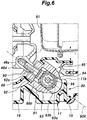
Figure 6 is an enlarged view of a part VI ofFigure 4 . - In the following, an embodiment of the present invention will be described in detail with reference to the drawings.
- As shown in
Figures 1 to 4 , an engine generator 1 includes an engine 2 (seeFigures 3 and4 ) and a generator 3 (seeFigures 3 and4 ) as power equipment driven by theengine 2. The engine generator 1 is engine power equipment that drives thegenerator 3 by theengine 2 to generate electricity. Theengine 2 and thegenerator 3 compose apower generation unit 4 as a power unit and are housed in acase 11. Thecase 11 is made of synthetic resin and defines an outline of the engine generator 1. In this sense, the engine generator 1 is an engine device including theengine 2 and thecase 11. - The
case 11 includes aleft side cover 12, aright side cover 13, afront cover 14, arear cover 15, and an undercover 16. Theleft side cover 12 and theright side cover 13 are integrally joined to each other, and a carryinghandle 17 for carrying the engine generator 1 is formed in the upper parts of theleft side cover 12 and theright side cover 13. A lattice-like reinforcement rib 17a is formed inside the carrying handle 17 (seeFigures 3 and4 ). Theleft side cover 12 is provided with an ignitionplug replacement lid 12a (seeFigure 1 and2 ), and theright side cover 13 is provided with amaintenance lid 13a (seeFigure 2 ). Thefront cover 14 is provided with anoperation panel 18, acontrol unit 19 arranged behind theoperation panel 18 so as to control the operations of theengine 2 and thegenerator 3, and aninverter unit 20 arranged behind thecontrol unit 19 so as to control the output frequency of thegenerator 3. Further, a lower part of thefront cover 14 is provided with an air introduction opening 14a (seeFigure 3 ) for introducing a cooling air and a fresh air, which is supplied to theengine 2, into thecase 11. Therear cover 15 is provided with a coolingair discharge opening 15a for discharging the cooling air from thecase 11 and an exhaust gas discharge opening 15b for discharging the burned gas of theengine 2. The undercover 16 is provided with fourrubber support legs 21 that abut against the ground or the floor when the engine generator 1 is placed thereon. - Left and right reinforcement frames 26 (only the
left reinforcement frame 26 is shown inFigures 1 and3 ) made of FRP are provided at the front of thecase 11. Eachreinforcement frame 26 is formed in an inverted L shape. Lower end of eachreinforcement frame 26 is fixed to a lateral surface of theunder cover 16 by abolt 28. Eachreinforcement frame 26 extends upward and inward in the lateral direction from the lower end thereof along an inner surface of the corresponding left and right side covers 12, 13. An upper end of eachreinforcement frame 26 is provided with anattachment part 26a that bends upward. The left andright reinforcement frames 26 have a gate-like shape as a whole, and are fastened together by screwing abolt 29 inserted from a side of theleft side cover 12 into an embeddednut 30 of theright side cover 13 in a state where theattachment parts 26a are opposed to each other and interposed between theleft side cover 12 and theright side cover 13 at the front of thecarrying handle 17. - As shown in
Figure 3 , a rubbertubular seal member 31 is attached to a portion where upper surfaces of theleft side cover 12, theright side cover 13, and thefront cover 14 are joined together. Afuel port 32a of afuel tank 32 arranged above theinverter unit 20 penetrates theseal member 31 from the bottom to the top, and is closed by adetachable cap 33.Protrusions 32b provided on both left and right side surfaces of thefuel tank 32 are loosely fitted to fueltank support parts 26b formed on the left and right reinforcement frames 26, respectively. Thereby, thefuel tank 32 is positioned so as not to vibrate. A rubber lower partvibration proof member 34 provided on an upper surface of theinverter unit 20 is opposed to a lower surface of thefuel tank 32 with a small gap. When thefuel tank 32 supplied with fuel expands and is deformed downward due to a load, the lower surface of thefuel tank 32 abuts against an upper surface of the lower partvibration proof member 34, so that the load of thefuel tank 32 is supported by theinverter unit 20. - Thus, the
fuel tank 32 is interposed laterally between theleft side cover 12 and theright side cover 13 so as to be supported by theleft side cover 12 and theright side cover 13. Therefore, thefuel tank 32 can be attached/detached by separating theleft side cover 12 and theright side cover 13. Moreover, thefuel tank 32 is surrounded by the left and right reinforcement frames 26, so that thefuel tank 32 can be protected from an impact applied from the outside. The left and right reinforcement frames 26 do not cover the entire engine generator 1, so that the weight is not significantly increased. - As shown in
Figure 2 , anelectric fuel pump 35 for supplying fuel in thefuel tank 32 to theengine 2 is provided on an inner surface of an upper portion of theright reinforcement frame 26. Afuel cock 36 that shuts off fuel to be supplied to theengine 2 and anengine switch 42 are provided on a lower outer surface of theright reinforcement frame 26. Anoperation knob 36a to open/close thefuel cock 36 penetrates theright side cover 13 so as to be exposed to the outside. Thus, thefuel pump 35 and thefuel cock 36 are supported by using theright reinforcement frame 26, so that a special support member is not required and the number of parts is reduced. Moreover, the fuel supply elements such as thefuel tank 32, thefuel pump 35, thefuel cock 36, and the like are collectively supported by the left and right reinforcement frames 26 instead of the left and right side covers 12, 13. Therefore, the left and right side covers 12, 13 can be easily detached when the maintenance of the fuel supply elements is performed. - A
fuel tube 37 that supplies fuel to thefuel cock 36 is connected to the bottom of thefuel tank 32, afuel tube 38 that supplies fuel to thefuel pump 35 is connected to thefuel cock 36, and afuel tube 39 that supplies fuel to acarburetor 41 arranged at a right side surface of acylinder head 50 of theengine 2 is connected to thefuel pump 35. A pulsation of an internal pressure of a crankcase of theengine 2 is transmitted to a diaphragm inside thefuel pump 35, so that thefuel pump 35 operates. - Next, the structure of the
power generation unit 4 will be described. As shown inFigures 4 and5 , theengine 2 consists of a four-cycle single cylinder engine that arranges a crank axis in the fore and aft direction and a cylinder axis vertically. Acrankcase 46 defines a crankchamber 46a for accommodating acrankshaft 45 and rotatably supports thecrankshaft 45. Thecrankcase 46 constitutes a lower part of theengine 2. Acylinder block 47 defines acylinder 47a having a lower end communicating with thecrank chamber 46a. Apiston 49 is slidably provided in thecylinder 47a and is connected to thecrankshaft 45 via a connectingrod 48. An upper end of thecylinder 47a is closed by acylinder head 50, and avalve actuation chamber 51a is formed between ahead cover 51 and thecylinder head 50. - The
crankcase 46 has a two-part structure and includes anupper half 46c that mainly constitutes a front half and alower half 46d that mainly constitutes a rear half. Theupper half 46c and thelower half 46d are joined to each other bybolts 52 on aninterface 46b which is inclined rearward and upward by about 50° with respect to the axis of thecrankshaft 45. Theupper half 46c of thecrankcase 46 is integrally formed with thecylinder block 47 and thecylinder head 50, and rotatably supports a front end side of thecrankshaft 45 via a ball bearing. Thelower half 46d of thecrankcase 46 rotatably supports a rear end side of thecrankshaft 45 via a ball bearing. - A lower part of the
crank chamber 46a defines an oil reservoir. Anoil level sensor 78 is attached to a bottom wall of thecrankcase 46. Acentrifugal governor 79 for speed control is attached to a rear wall of thecrankcase 46 behind theoil level sensor 78. Thecentrifugal governor 79 is provided with a rotating disk rotatably supported by a support shaft fixed to an inner surface of thelower half 46d of thecrankcase 46, and a driven gear and a lubricating oil splashing blade are integrally formed on an outer circumference of the rotating disk. - The
head cover 51 includes an ignition plug attachment/detachment hole 51b, and is detachably joined to thecylinder head 50 by four bolts 53 (seeFigure 5 ). - As shown in
Figure 4 , thegenerator 3 consists of an outer-rotor type generator provided in a cantilever manner on a shaft end of thecrankshaft 45 protruding forward from thecrankcase 46. Thegenerator 3 includes a stator composed of acoil 54 fixed to a front surface of thecrankcase 46 and a rotor composed of apermanent magnet 56 fixed to an inner circumferential surface of aflywheel 55 fixed to thecrankshaft 45. Thepermanent magnet 56 is opposed to the outer circumferential surface of thecoil 54. A coolingfan 57 is coaxially fixed to a front surface of theflywheel 55. - As shown in
Figures 2 and5 , anair cleaner 59 connected to thecarburetor 41 by anintake pipe 58 is arranged in front of thecarburetor 41. As shown inFigures 3 and5 , a front end of anexhaust pipe 60 extending rearward is connected to a left side surface of thecylinder head 50 of theengine 2, and a box-shapedmuffler 61 is connected to a rear end of theexhaust pipe 60. As shown inFigure 4 , themuffler 61 internally defines an expansion chamber for silencing, and accommodates anexhaust catalyst 62 for purifying exhaust gas. Themuffler 61 is arranged behind theengine 2 such that anoutlet opening 63a of anoutlet pipe 63 extending rearward from theexhaust catalyst 62 is opposed to the exhaust gas discharge opening 15b of therear cover 15. Themuffler 61 is fixed to a rear surface of theengine 2 by bolts. - As shown in
Figure 5 , ashroud 66, which is made of synthetic resin, covers theengine 2. Theshroud 66 includes aleft shroud half 67 and aright shroud half 68. Theleft shroud half 67 is fastened to left side surfaces of thecrankcase 46 and thecylinder block 47 of theengine 2 by two bolts 69 (seeFigures 3 and5 ). Theright shroud half 68 is fastened to right side surfaces of thecrankcase 46 and thecylinder block 47 of theengine 2 by two bolts 70 (only onebolt 70 is shown inFigure 5 ). - As shown in
Figure 4 , theshroud 66 has openings on a front surface and a rear surface thereof. An outer circumference of themuffler 61 is fitted to the opening on the rear surface of theshroud 66 with a gap therebetween. Afan cover 71 made of die-cast aluminum is fitted to theshroud 66 so as to cover the opening on the front surface of theshroud 66. Thefan cover 71 is fastened to thecylinder head 50 and thecrankcase 46 of theengine 2 by bolts, and covers thegenerator 3 and the coolingfan 57. - A
recoil starter 75 is fixed to an opening formed at a front end of thefan cover 71 by bolts. Therecoil starter 75 includes a reel, an operation cable, and a driving member. The reel is rotatably supported by a recoil starter cover. One end side of the operation cable is wound around the reel, and another end side of the operation cable penetrates through theright reinforcement frame 26 and theright side cover 13. The driving member is provided on the reel and detachably engaged with a driven member integrated with the coolingfan 57. When the operation cable is pulled and the reel is rotated, the driving member is engaged with the driven member so as to rotate the coolingfan 57, and thereby thecrankshaft 45 connected to the coolingfan 57 via theflywheel 55 is cranked, so that theengine 2 can be started. - When the
engine 2 is started, the coolingfan 57 provided on theflywheel 55 of thegenerator 3 rotates in theshroud 66. Due to the negative pressure generated by the rotation of the coolingfan 57, the outside air passes through the air introduction opening 14a (seeFigure 3 ) of thefront cover 14 and is introduced into thecase 11 as cooling air. The cooling air cools thegenerator 3, theengine 2, and themuffler 61 that are housed inside thefan cover 71 and theshroud 66. Thereafter, the cooling air is discharged to the outside of thecase 11 from the coolingair discharge opening 15a of therear cover 15. - As shown in
Figures 2 and4 , upper parts of theleft shroud half 67 and theright shroud half 68 are provided with connection parts connected with thefan cover 71, and the connection parts are provided with arectangular opening 66a surrounded by the upper parts thereof. The head cover 51 of theengine 2 protrudes to the outside of theshroud 66 via theopening 66a. Thehead cover 51 is provided with the ignition plug attachment/detachment hole 51b into which anignition plug 76 is inserted. The ignition plug attachment/detachment hole 51b is closed by adetachable plug cap 77. An ignition coil 65 (seeFigure 3 ) is provided at an upper end of thefan cover 71 adjacent to theignition plug 76. - As shown in
Figures 1 and2 , theplug cap 77 is opposed to the ignitionplug replacement lid 12a of theleft side cover 12, so that the maintenance of theignition plug 76 can be easily performed by simply opening the ignitionplug replacement lid 12a and removing theplug cap 77. Further, when theleft side cover 12 and theright side cover 13 are detached, the maintenance of the valve actuation mechanism covered by the head cover 51 (for example, the adjustment of a tappet clearance) can be easily performed by detaching thehead cover 51 exposed from theshroud 66 without detaching theleft shroud half 67 and theright shroud half 68. - As shown in
Figures 3 to 5 , thepower generation unit 4 is attached to thecase 11 via three support parts of an upperportion support part 81, a rear lowerportion support part 82, and a front lowerportion support part 83. The upperportion support part 81 attaches an upper portion of theengine 2 to a rear part of the carryinghandle 17 of thecase 11. The rear lowerportion support part 82 attaches a rear lower portion of theengine 2 to a rear part of theunder cover 16 of thecase 11. The front lowerportion support part 83 attaches a front lower portion of thefan cover 71 to a front part of theunder cover 16 of thecase 11. - First, the upper
portion support part 81 will be described. Asupport plate 51c extending in the fore and aft direction protrudes on an upper surface of thehead cover 51 of theengine 2. A pair of left andright rubber bushings 85 are fitted to a circular support hole 5 1d formed in the center of thesupport plate 51c, and acollar 86 is inserted into the pair of left andright rubber bushings 85. In a state wherewashers 88 are arranged at both ends of the pair of left andright rubber bushings 85, both ends of a connectingpin 89 penetrating through thewashers 88 and thecollar 86 are fitted to a pair ofattachment bosses 11a as mounting parts (seeFigure 5 ) formed on theleft side cover 12 and theright side cover 13 at the rear of the carryinghandle 17. Thereby, thesupport plate 51c of thehead cover 51 is elastically supported by thecase 11 via therubber bushings 85. - Next, the rear lower
portion support part 82 will be described. As shown inFigures 5 and6 , twoscrew holes 46e with bottoms are formed at a rear corner of a bottom of thecrankcase 46 of theengine 2. The twoscrew holes 46e are parallel to each other and formed obliquely inward so as to have an upward and forward inclination angle of about 40°. Anattachment bracket 91 is fixed to the rear corner of the bottom of thecrankcase 46 of theengine 2 by twofastening bolts 90 screwed into thescrew holes 46e. The twofastening bolts 90 have mutuallyparallel axes 90X orthogonal to theinterface 46b (seeFigure 4 ) of thecrankcase 46. That is, thescrew holes 46e are orthogonal to theinterface 46b like insertion holes of thebolts 52 for fastening thelower half 46d of thecrankcase 46 to theupper half 46c thereof are orthogonal to theinterface 46b, so that thescrew holes 46e can be formed easily. - The
attachment bracket 91 includes amain part 92 having two throughholes 92a through which thefastening bolts 90 penetrate and twocylindrical parts 93 extending obliquely downward and rearward from themain part 92 and protruding to the outside of theshroud 66 from anopening 66b formed in a rear lower part of theshroud 66. Each of thecylindrical parts 93 defines anattachment hole 93a having an axis extending laterally. Theattachment bracket 91 supports theshroud 66 by holding an edge of theopening 66b of theshroud 66 by thecylindrical parts 93. The twocylindrical parts 93 are separated by anotch 93b provided on theaxes 90X of thefastening bolts 90. The twocylindrical parts 93 are integrated with each other on a side of themain part 92, namely, on a side excluding thenotch 93b. Thenotch 93b has a size to allow penetration of thefastening bolts 90 and entry of a tool that engages with the heads of thefastening bolts 90 when thefastening bolts 90 are attached/detached. That is, the two throughholes 92a are provided in a part of themain part 92 corresponding to thenotch 93b (a part of themain part 92 between the two cylindrical parts 93). Accordingly, it is possible to prevent the size of theattachment bracket 91 from increasing. A pair of left and rightcylindrical rubber bushings 94 are fitted to thecylindrical parts 93 such that a part of eachrubber bushing 94 in the axial direction is inserted into eachcylindrical part 93. - On a lower rear side of the
case 11, a pair of left andright attachment ribs 11b as mounting parts are formed so as to protrude upward from a rear upper surface of theunder cover 16. Acollar 95 is inserted intosupport holes 11d provided in the pair ofattachment ribs 11b so that both ends of thecollar 95 are supported by thesupport holes 11d. The pair ofrubber bushings 94 are interposed between a pair of left andright washers 98 and supported on an outer circumference of a middle portion of thecollar 95. A mountingbolt 96, which is inserted from theattachment boss 11a formed in theright side cover 13, penetrates through thecollar 95. The mountingbolt 96 is fastened to an embeddednut 97 provided in theattachment boss 11a formed in theleft side cover 12. Accordingly, theattachment bracket 91 exposed from theshroud 66 is elastically supported by theunder cover 16 via therubber bushings 94. Thereby, it is possible to prevent the vibration of theengine 2 from being transmitted to thecase 11. Further, thecollar 95 is provided inside therubber bushings 94, and the mountingbolt 96 is provided in thecollar 95. Thereby, therubber bushings 94 are not pressed against the mountingbolt 96 when the mountingbolt 96 is tightened. Therefore, the mountingbolt 96 can be securely fastened to the embeddednut 97. - The mounting
bolt 96 and thecollar 95 surrounding the mountingbolt 96 extend in the horizontal direction (the direction orthogonal to the vertical plane including an axis of thecylinder 47a). The twocylindrical parts 93 surround the axial middle parts of the mountingbolt 96 and thecollar 95, and are attached to theattachment bosses 11a via the mountingbolt 96 and thecollar 95. Theaxes 90X of thefastening bolts 90 are orthogonal to theinterface 46b (seeFigure 4 ) of thecrankcase 46, and are orthogonal to thecollar 95 and mountingbolt 96. Therefore, thecollar 95 and the mountingbolt 96 at least partially overlap with thefastening bolts 90 when viewed in the axial direction of thefastening bolts 90. Therefore, the load transmitted from theengine 2 to theattachment bracket 91 via thefastening bolts 90 is linearly transmitted to thecollar 95. Accordingly, the bending moment acting on theattachment bracket 91 becomes small, and the bending moment acting on thefastening bolts 90 and thescrew holes 46e also becomes small. Therefore, it is possible to prevent the support stiffness in the rear lowerportion support part 82 from being lowered. - The front lower
portion support part 83 will be described. As shown inFigure 4 , anattachment bracket 71a is integrally formed on a lower portion of thefan cover 71. A pair of left andright attachment ribs 11c as mounting parts are formed on a lower front side of thecase 11 and protrude upward from a front upper surface of theunder cover 16. Theattachment bracket 71a is elastically supported by the pair of left andright attachment ribs 11c via a mountingbolt 96 and arubber bushing 94. The support structure of theattachment bracket 71a is substantially the same as the support structure of theattachment bracket 91. - As shown in
Figures 4 and5 , when the user lifts the carrying handle 17 to carry the engine generator 1, most of the load of thepower generation unit 4 including theengine 2 and thegenerator 3 is transmitted from thesupport plate 51c of thehead cover 51 to the carryinghandle 17 of thecase 11 via therubber bushings 85, the connectingpin 89, and theattachment bosses 11a. That is, thepower generation unit 4 comes to be directly suspended from the carryinghandle 17, so that it is not necessary to support the load of thepower generation unit 4 by thecase 11 itself. Accordingly, it is possible to reduce the thickness and weight of thecase 11 that extends downward from the carryinghandle 17. In addition, the flexibility in designing the shape and material of thecase 11 is significantly increased. - As shown in
Figure 3 , a front part of theunder cover 16 that supports a lower front part of thepower generation unit 4 is joined to a front part of the carryinghandle 17 via the left and right reinforcement frames 26 having high stiffness. Therefore, theleft side cover 12 and theright side cover 13 do not bear the load, but the carryinghandle 17 bears the load dispersed back and forth. Therefore, it is possible to reduce the bending stress generated in thecase 11 near the carryinghandle 17. - On the other hand, in a state where the engine generator 1 is placed on the ground or the floor, most of the load of the
power generation unit 4 is directly transmitted to theunder cover 16 provided with thesupport legs 21. Therefore, even if the stiffness of theleft side cover 12 and theright side cover 13 is set to be low, the deformation due to the load does not occur. - Further, the
power generation unit 4 is elastically supported by thecase 11 at three parts of the upperportion support part 81, the rear lowerportion support part 82, and the front lowerportion support part 83, so that the load of thepower generation unit 4 is dispersed to each part of thecase 11. Moreover, according to the vibration absorbing effect of therubber bushings engine 2 to the carryinghandle 17 but also the resonance of thecase 11 due to the vibration of theengine 2. - In a state where the engine generator 1 is placed on the ground or the floor, the
left side cover 12 and theright side cover 13 can be separated from theunder cover 16 by simply removing the fourbolts engine 2 and thegenerator 3 can be exposed and easily maintained without bedding the engine generator 1. - In the engine generator 1 of the present embodiment, the
fastening bolts 90 that fasten theattachment bracket 91 to thecrankcase 46 penetrate through the throughholes 92a of theattachment bracket 91 and are screwed into thescrew holes 46e formed obliquely inward at the corner of the bottom of thecrankcase 46. Therefore, it is possible to enlarge the space inside thecase 11 without lowering the support stiffness of the rear lowerportion support part 82. That is, as shown by imaginary lines inFigure 6 , if theattachment bracket 91 protrudes horizontally rearward, the position of theattachment bracket 91 is relatively high and the space above theattachment bracket 91 is relatively small. On the other hand, with the above configuration, theattachment bracket 91 is displaced downward, and the space inside thecase 11 is enlarged accordingly. Therefore, it is possible to increase the size of themuffler 61 arranged on an upper side of theattachment bracket 91 inside thecase 11. Accordingly, it is possible to increase the size of theexhaust catalyst 62 and thereby to improve the exhaust purification performance without reducing the muffling effect of themuffler 61. - Concrete embodiments of the present invention have been described in the foregoing, but the present invention should not be limited by the foregoing embodiments and various modifications and alterations are possible. For example, in the above embodiments, the present invention is applied to the engine generator 1. However, the present invention may be applied to other engine power equipment such as an engine pump and a construction machine, or may be applied to an engine device including an engine for driving power equipment separated therefrom. Also, a specific configuration, an arrangement, quantity, an angle, and the like of each member and each portion thereof can be changed as appropriate within the scope of the present invention. Further, not all of the structural elements shown in the above embodiments are necessarily indispensable and they may be selectively adopted as appropriate.
-
1: engine generator (engine device) 2: engine 3: generator (power equipment) 4: power generation unit 11: case 11b: attachment ribs (mounting parts) 11d: support holes 45: crankshaft 46: crankcase 46b: interface 46c: upper half (first half) 46d: lower half (second half) 46e: screw hole 61: muffler 62: exhaust catalyst 81: upper portion support part 82: rear lower portion support part 83: front lower portion support part 90: fastening bolt 90X: axis 91: attachment bracket 92: main part 92a: through hole 93: cylindrical part 93a: attachment hole 94: rubber bushing 95: collar (mounting axial member) 96: mounting bolt (mounting axial member)
Claims (7)
- An engine device comprising:an engine; anda case that accommodates the engine,wherein the engine includes a crankcase constituting a lower part thereof and is attached to the case via support parts,at least one of the support parts includes a mounting part provided in the case and an attachment bracket fastened to a bottom of the crankcase by a fastening bolt and attached to the mounting part, andthe fastening bolt penetrates through a through hole provided in the attachment bracket and is screwed into a screw hole formed obliquely inward at a corner of the bottom of the crankcase.
- The engine device according to claim 1, wherein the crankcase includes a first half and a second half joined to each other by bolts on an interface formed obliquely with respect to a crank axis, and
the second half is provided with the screw hole, and the screw hole is orthogonal to the interface. - The engine device according to claim 2, wherein the attachment bracket is attached to the mounting part via a mounting axial member penetrating horizontally through an attachment hole provided in the attachment bracket and a support hole provided in the mounting part, and
the mounting axial member at least partially overlaps with the fastening bolt when viewed in an axial direction of the fastening bolt. - The engine device according to claim 3, wherein the mounting part is provided at each of two ends of the mounting axial member,
the attachment bracket includes two cylindrical parts surrounding a middle part of the mounting axial member between the two ends thereof, and
each cylindrical part is supported by the mounting axial member via a rubber bushing provided between an outer circumference of the mounting axial member and an inner circumference of the cylindrical part. - The engine device according to claim 4, wherein the through hole is provided inside a part of the attachment bracket between the two cylindrical parts.
- The engine device according to claim 4, wherein the mounting axial member includes a mounting bolt and a collar surrounding the mounting bolt.
- The engine device according to any one of claims 1 to 5, further comprising a muffler accommodating an exhaust catalyst and provided in a space defined between the case and a side of the engine where the attachment bracket is attached.
Applications Claiming Priority (1)
| Application Number | Priority Date | Filing Date | Title |
|---|---|---|---|
| PCT/JP2017/044444 WO2019116434A1 (en) | 2017-12-11 | 2017-12-11 | Engine device |
Publications (3)
| Publication Number | Publication Date |
|---|---|
| EP3693569A1 true EP3693569A1 (en) | 2020-08-12 |
| EP3693569A4 EP3693569A4 (en) | 2020-10-28 |
| EP3693569B1 EP3693569B1 (en) | 2022-04-20 |
Family
ID=66819053
Family Applications (1)
| Application Number | Title | Priority Date | Filing Date |
|---|---|---|---|
| EP17934924.6A Active EP3693569B1 (en) | 2017-12-11 | 2017-12-11 | Engine device |
Country Status (5)
| Country | Link |
|---|---|
| US (1) | US11143139B2 (en) |
| EP (1) | EP3693569B1 (en) |
| JP (1) | JP6773921B2 (en) |
| CN (1) | CN111433444B (en) |
| WO (1) | WO2019116434A1 (en) |
Families Citing this family (2)
| Publication number | Priority date | Publication date | Assignee | Title |
|---|---|---|---|---|
| CN113357039B (en) * | 2021-07-19 | 2022-06-03 | 赣州市领沃电子科技有限公司 | Detachable engine harness plastic shell protection shell |
| US11732634B1 (en) * | 2022-05-25 | 2023-08-22 | Kawasaki Motors, Ltd. | Engine |
Family Cites Families (20)
| Publication number | Priority date | Publication date | Assignee | Title |
|---|---|---|---|---|
| US2287399A (en) * | 1939-12-23 | 1942-06-23 | Packard Motor Car Co | Internal combustion engine |
| JPS6140425A (en) * | 1984-07-31 | 1986-02-26 | Yanmar Diesel Engine Co Ltd | Case containing type engine generator |
| JPS6132897U (en) * | 1984-07-31 | 1986-02-27 | ヤンマーディーゼル株式会社 | engine mounting device |
| US4729353A (en) * | 1986-12-29 | 1988-03-08 | Engineered Air Systems, Inc. | Fuel container support system for a combustion engine |
| DE4413255A1 (en) * | 1994-04-16 | 1995-10-19 | Bayerische Motoren Werke Ag | Method for breaking separation of the bearing cover of a multi-part bearing arrangement, in particular in crankcases of internal combustion engines |
| JPH10121959A (en) * | 1996-10-15 | 1998-05-12 | Yamaha Motor Co Ltd | Water cooling device for multi-cylinder internal combustion engine |
| JP3418079B2 (en) * | 1997-01-24 | 2003-06-16 | 澤藤電機株式会社 | Power generator |
| JP3340665B2 (en) * | 1998-01-19 | 2002-11-05 | 本田技研工業株式会社 | Engine working machine |
| JP3347044B2 (en) * | 1998-01-19 | 2002-11-20 | 本田技研工業株式会社 | Portable engine working machine |
| JP3871829B2 (en) * | 1999-07-12 | 2007-01-24 | 本田技研工業株式会社 | Engine generator |
| JP3754579B2 (en) * | 1999-07-12 | 2006-03-15 | 本田技研工業株式会社 | Engine working machine |
| JP3886002B2 (en) * | 2002-03-27 | 2007-02-28 | ヤマハ発動機株式会社 | Engine generator |
| CN100427746C (en) * | 2006-09-30 | 2008-10-22 | 无锡开普动力有限公司 | Four-stroke engine |
| JP4475327B2 (en) * | 2007-12-21 | 2010-06-09 | トヨタ自動車株式会社 | Bracket fastening structure |
| CN103016138A (en) * | 2012-11-07 | 2013-04-03 | 沈阳航天三菱汽车发动机制造有限公司 | Turbocharged engine |
| JP6725269B2 (en) | 2016-03-09 | 2020-07-15 | 本田技研工業株式会社 | Overhead camshaft engine |
| JP6839923B2 (en) * | 2016-03-11 | 2021-03-10 | 三菱重工サーマルシステムズ株式会社 | In-vehicle device and electric compressor |
| JP6666177B2 (en) * | 2016-03-15 | 2020-03-13 | 本田技研工業株式会社 | Engine driven work machine |
| JP2017166400A (en) * | 2016-03-16 | 2017-09-21 | 本田技研工業株式会社 | Engine drive work machine |
| CN205663509U (en) * | 2016-06-03 | 2016-10-26 | 韩群山 | It mixes generator and engine crankshaft coupling device to increase form electricity |
-
2017
- 2017-12-11 JP JP2019559437A patent/JP6773921B2/en active Active
- 2017-12-11 WO PCT/JP2017/044444 patent/WO2019116434A1/en unknown
- 2017-12-11 CN CN201780097356.3A patent/CN111433444B/en active Active
- 2017-12-11 EP EP17934924.6A patent/EP3693569B1/en active Active
- 2017-12-11 US US16/758,931 patent/US11143139B2/en active Active
Also Published As
| Publication number | Publication date |
|---|---|
| WO2019116434A1 (en) | 2019-06-20 |
| CN111433444A (en) | 2020-07-17 |
| JP6773921B2 (en) | 2020-10-21 |
| EP3693569A4 (en) | 2020-10-28 |
| EP3693569B1 (en) | 2022-04-20 |
| US11143139B2 (en) | 2021-10-12 |
| CN111433444B (en) | 2021-09-03 |
| US20200309062A1 (en) | 2020-10-01 |
| JPWO2019116434A1 (en) | 2020-07-16 |
Similar Documents
| Publication | Publication Date | Title |
|---|---|---|
| KR100394383B1 (en) | Engine generating machine | |
| KR100348872B1 (en) | Engine operated machine | |
| EP3693569B1 (en) | Engine device | |
| JP4145912B2 (en) | Engine working machine | |
| EP3219952B1 (en) | Engine-driven working machine | |
| JP2007002713A (en) | Muffler cover structure for general-purpose engine | |
| JP4785624B2 (en) | Internal combustion engine having an electrical holder | |
| JPH1182049A (en) | Auxiliary machine mounting structure for internal combustion engine | |
| JP4145911B2 (en) | Engine working machine | |
| JP3754697B2 (en) | Engine working machine | |
| JP3871829B2 (en) | Engine generator | |
| JP4145899B2 (en) | Engine generator | |
| JP2722089B2 (en) | Engine work machine assembly | |
| JP2001027125A (en) | Engine generator | |
| JP2004353677A5 (en) | ||
| JP2005282581A5 (en) |
Legal Events
| Date | Code | Title | Description |
|---|---|---|---|
| STAA | Information on the status of an ep patent application or granted ep patent |
Free format text: STATUS: THE INTERNATIONAL PUBLICATION HAS BEEN MADE |
|
| PUAI | Public reference made under article 153(3) epc to a published international application that has entered the european phase |
Free format text: ORIGINAL CODE: 0009012 |
|
| STAA | Information on the status of an ep patent application or granted ep patent |
Free format text: STATUS: REQUEST FOR EXAMINATION WAS MADE |
|
| 17P | Request for examination filed |
Effective date: 20200504 |
|
| AK | Designated contracting states |
Kind code of ref document: A1 Designated state(s): AL AT BE BG CH CY CZ DE DK EE ES FI FR GB GR HR HU IE IS IT LI LT LU LV MC MK MT NL NO PL PT RO RS SE SI SK SM TR |
|
| AX | Request for extension of the european patent |
Extension state: BA ME |
|
| A4 | Supplementary search report drawn up and despatched |
Effective date: 20200930 |
|
| RIC1 | Information provided on ipc code assigned before grant |
Ipc: F02F 7/00 20060101ALI20200924BHEP Ipc: F02F 1/00 20060101ALI20200924BHEP Ipc: F02B 63/04 20060101AFI20200924BHEP |
|
| STAA | Information on the status of an ep patent application or granted ep patent |
Free format text: STATUS: EXAMINATION IS IN PROGRESS |
|
| STAA | Information on the status of an ep patent application or granted ep patent |
Free format text: STATUS: EXAMINATION IS IN PROGRESS |
|
| 17Q | First examination report despatched |
Effective date: 20201204 |
|
| DAV | Request for validation of the european patent (deleted) | ||
| DAX | Request for extension of the european patent (deleted) | ||
| STAA | Information on the status of an ep patent application or granted ep patent |
Free format text: STATUS: EXAMINATION IS IN PROGRESS |
|
| GRAP | Despatch of communication of intention to grant a patent |
Free format text: ORIGINAL CODE: EPIDOSNIGR1 |
|
| STAA | Information on the status of an ep patent application or granted ep patent |
Free format text: STATUS: GRANT OF PATENT IS INTENDED |
|
| INTG | Intention to grant announced |
Effective date: 20220202 |
|
| GRAS | Grant fee paid |
Free format text: ORIGINAL CODE: EPIDOSNIGR3 |
|
| GRAA | (expected) grant |
Free format text: ORIGINAL CODE: 0009210 |
|
| STAA | Information on the status of an ep patent application or granted ep patent |
Free format text: STATUS: THE PATENT HAS BEEN GRANTED |
|
| AK | Designated contracting states |
Kind code of ref document: B1 Designated state(s): AL AT BE BG CH CY CZ DE DK EE ES FI FR GB GR HR HU IE IS IT LI LT LU LV MC MK MT NL NO PL PT RO RS SE SI SK SM TR |
|
| REG | Reference to a national code |
Ref country code: GB Ref legal event code: FG4D |
|
| REG | Reference to a national code |
Ref country code: CH Ref legal event code: EP |
|
| REG | Reference to a national code |
Ref country code: IE Ref legal event code: FG4D |
|
| REG | Reference to a national code |
Ref country code: DE Ref legal event code: R096 Ref document number: 602017056412 Country of ref document: DE |
|
| REG | Reference to a national code |
Ref country code: AT Ref legal event code: REF Ref document number: 1485308 Country of ref document: AT Kind code of ref document: T Effective date: 20220515 |
|
| REG | Reference to a national code |
Ref country code: LT Ref legal event code: MG9D |
|
| REG | Reference to a national code |
Ref country code: NL Ref legal event code: MP Effective date: 20220420 |
|
| REG | Reference to a national code |
Ref country code: AT Ref legal event code: MK05 Ref document number: 1485308 Country of ref document: AT Kind code of ref document: T Effective date: 20220420 |
|
| PG25 | Lapsed in a contracting state [announced via postgrant information from national office to epo] |
Ref country code: NL Free format text: LAPSE BECAUSE OF FAILURE TO SUBMIT A TRANSLATION OF THE DESCRIPTION OR TO PAY THE FEE WITHIN THE PRESCRIBED TIME-LIMIT Effective date: 20220420 |
|
| PG25 | Lapsed in a contracting state [announced via postgrant information from national office to epo] |
Ref country code: SE Free format text: LAPSE BECAUSE OF FAILURE TO SUBMIT A TRANSLATION OF THE DESCRIPTION OR TO PAY THE FEE WITHIN THE PRESCRIBED TIME-LIMIT Effective date: 20220420 Ref country code: PT Free format text: LAPSE BECAUSE OF FAILURE TO SUBMIT A TRANSLATION OF THE DESCRIPTION OR TO PAY THE FEE WITHIN THE PRESCRIBED TIME-LIMIT Effective date: 20220822 Ref country code: NO Free format text: LAPSE BECAUSE OF FAILURE TO SUBMIT A TRANSLATION OF THE DESCRIPTION OR TO PAY THE FEE WITHIN THE PRESCRIBED TIME-LIMIT Effective date: 20220720 Ref country code: LT Free format text: LAPSE BECAUSE OF FAILURE TO SUBMIT A TRANSLATION OF THE DESCRIPTION OR TO PAY THE FEE WITHIN THE PRESCRIBED TIME-LIMIT Effective date: 20220420 Ref country code: HR Free format text: LAPSE BECAUSE OF FAILURE TO SUBMIT A TRANSLATION OF THE DESCRIPTION OR TO PAY THE FEE WITHIN THE PRESCRIBED TIME-LIMIT Effective date: 20220420 Ref country code: GR Free format text: LAPSE BECAUSE OF FAILURE TO SUBMIT A TRANSLATION OF THE DESCRIPTION OR TO PAY THE FEE WITHIN THE PRESCRIBED TIME-LIMIT Effective date: 20220721 Ref country code: FI Free format text: LAPSE BECAUSE OF FAILURE TO SUBMIT A TRANSLATION OF THE DESCRIPTION OR TO PAY THE FEE WITHIN THE PRESCRIBED TIME-LIMIT Effective date: 20220420 Ref country code: ES Free format text: LAPSE BECAUSE OF FAILURE TO SUBMIT A TRANSLATION OF THE DESCRIPTION OR TO PAY THE FEE WITHIN THE PRESCRIBED TIME-LIMIT Effective date: 20220420 Ref country code: BG Free format text: LAPSE BECAUSE OF FAILURE TO SUBMIT A TRANSLATION OF THE DESCRIPTION OR TO PAY THE FEE WITHIN THE PRESCRIBED TIME-LIMIT Effective date: 20220720 Ref country code: AT Free format text: LAPSE BECAUSE OF FAILURE TO SUBMIT A TRANSLATION OF THE DESCRIPTION OR TO PAY THE FEE WITHIN THE PRESCRIBED TIME-LIMIT Effective date: 20220420 |
|
| PG25 | Lapsed in a contracting state [announced via postgrant information from national office to epo] |
Ref country code: RS Free format text: LAPSE BECAUSE OF FAILURE TO SUBMIT A TRANSLATION OF THE DESCRIPTION OR TO PAY THE FEE WITHIN THE PRESCRIBED TIME-LIMIT Effective date: 20220420 Ref country code: PL Free format text: LAPSE BECAUSE OF FAILURE TO SUBMIT A TRANSLATION OF THE DESCRIPTION OR TO PAY THE FEE WITHIN THE PRESCRIBED TIME-LIMIT Effective date: 20220420 Ref country code: LV Free format text: LAPSE BECAUSE OF FAILURE TO SUBMIT A TRANSLATION OF THE DESCRIPTION OR TO PAY THE FEE WITHIN THE PRESCRIBED TIME-LIMIT Effective date: 20220420 Ref country code: IS Free format text: LAPSE BECAUSE OF FAILURE TO SUBMIT A TRANSLATION OF THE DESCRIPTION OR TO PAY THE FEE WITHIN THE PRESCRIBED TIME-LIMIT Effective date: 20220820 |
|
| REG | Reference to a national code |
Ref country code: DE Ref legal event code: R097 Ref document number: 602017056412 Country of ref document: DE |
|
| PG25 | Lapsed in a contracting state [announced via postgrant information from national office to epo] |
Ref country code: SM Free format text: LAPSE BECAUSE OF FAILURE TO SUBMIT A TRANSLATION OF THE DESCRIPTION OR TO PAY THE FEE WITHIN THE PRESCRIBED TIME-LIMIT Effective date: 20220420 Ref country code: SK Free format text: LAPSE BECAUSE OF FAILURE TO SUBMIT A TRANSLATION OF THE DESCRIPTION OR TO PAY THE FEE WITHIN THE PRESCRIBED TIME-LIMIT Effective date: 20220420 Ref country code: RO Free format text: LAPSE BECAUSE OF FAILURE TO SUBMIT A TRANSLATION OF THE DESCRIPTION OR TO PAY THE FEE WITHIN THE PRESCRIBED TIME-LIMIT Effective date: 20220420 Ref country code: EE Free format text: LAPSE BECAUSE OF FAILURE TO SUBMIT A TRANSLATION OF THE DESCRIPTION OR TO PAY THE FEE WITHIN THE PRESCRIBED TIME-LIMIT Effective date: 20220420 Ref country code: DK Free format text: LAPSE BECAUSE OF FAILURE TO SUBMIT A TRANSLATION OF THE DESCRIPTION OR TO PAY THE FEE WITHIN THE PRESCRIBED TIME-LIMIT Effective date: 20220420 Ref country code: CZ Free format text: LAPSE BECAUSE OF FAILURE TO SUBMIT A TRANSLATION OF THE DESCRIPTION OR TO PAY THE FEE WITHIN THE PRESCRIBED TIME-LIMIT Effective date: 20220420 |
|
| PLBE | No opposition filed within time limit |
Free format text: ORIGINAL CODE: 0009261 |
|
| STAA | Information on the status of an ep patent application or granted ep patent |
Free format text: STATUS: NO OPPOSITION FILED WITHIN TIME LIMIT |
|
| 26N | No opposition filed |
Effective date: 20230123 |
|
| PG25 | Lapsed in a contracting state [announced via postgrant information from national office to epo] |
Ref country code: AL Free format text: LAPSE BECAUSE OF FAILURE TO SUBMIT A TRANSLATION OF THE DESCRIPTION OR TO PAY THE FEE WITHIN THE PRESCRIBED TIME-LIMIT Effective date: 20220420 |
|
| PG25 | Lapsed in a contracting state [announced via postgrant information from national office to epo] |
Ref country code: SI Free format text: LAPSE BECAUSE OF FAILURE TO SUBMIT A TRANSLATION OF THE DESCRIPTION OR TO PAY THE FEE WITHIN THE PRESCRIBED TIME-LIMIT Effective date: 20220420 |
|
| REG | Reference to a national code |
Ref country code: CH Ref legal event code: PL |
|
| GBPC | Gb: european patent ceased through non-payment of renewal fee |
Effective date: 20221211 |
|
| REG | Reference to a national code |
Ref country code: BE Ref legal event code: MM Effective date: 20221231 |
|
| PG25 | Lapsed in a contracting state [announced via postgrant information from national office to epo] |
Ref country code: LU Free format text: LAPSE BECAUSE OF NON-PAYMENT OF DUE FEES Effective date: 20221211 |
|
| PG25 | Lapsed in a contracting state [announced via postgrant information from national office to epo] |
Ref country code: LI Free format text: LAPSE BECAUSE OF NON-PAYMENT OF DUE FEES Effective date: 20221231 Ref country code: IE Free format text: LAPSE BECAUSE OF NON-PAYMENT OF DUE FEES Effective date: 20221211 Ref country code: GB Free format text: LAPSE BECAUSE OF NON-PAYMENT OF DUE FEES Effective date: 20221211 Ref country code: CH Free format text: LAPSE BECAUSE OF NON-PAYMENT OF DUE FEES Effective date: 20221231 |
|
| PG25 | Lapsed in a contracting state [announced via postgrant information from national office to epo] |
Ref country code: BE Free format text: LAPSE BECAUSE OF NON-PAYMENT OF DUE FEES Effective date: 20221231 |
|
| PG25 | Lapsed in a contracting state [announced via postgrant information from national office to epo] |
Ref country code: IT Free format text: LAPSE BECAUSE OF FAILURE TO SUBMIT A TRANSLATION OF THE DESCRIPTION OR TO PAY THE FEE WITHIN THE PRESCRIBED TIME-LIMIT Effective date: 20220420 |
|
| PGFP | Annual fee paid to national office [announced via postgrant information from national office to epo] |
Ref country code: FR Payment date: 20231009 Year of fee payment: 7 Ref country code: DE Payment date: 20231017 Year of fee payment: 7 |
|
| PG25 | Lapsed in a contracting state [announced via postgrant information from national office to epo] |
Ref country code: CY Free format text: LAPSE BECAUSE OF FAILURE TO SUBMIT A TRANSLATION OF THE DESCRIPTION OR TO PAY THE FEE WITHIN THE PRESCRIBED TIME-LIMIT Effective date: 20220420 |