EP3693559B1 - Stützvorrichtung für ein zentrales entlüftungsrohr eines turbofantriebwerks - Google Patents
Stützvorrichtung für ein zentrales entlüftungsrohr eines turbofantriebwerks Download PDFInfo
- Publication number
- EP3693559B1 EP3693559B1 EP18863980.1A EP18863980A EP3693559B1 EP 3693559 B1 EP3693559 B1 EP 3693559B1 EP 18863980 A EP18863980 A EP 18863980A EP 3693559 B1 EP3693559 B1 EP 3693559B1
- Authority
- EP
- European Patent Office
- Prior art keywords
- wall portion
- ring
- sleeve
- support device
- pressure shaft
- Prior art date
- Legal status (The legal status is an assumption and is not a legal conclusion. Google has not performed a legal analysis and makes no representation as to the accuracy of the status listed.)
- Active
Links
Images






Classifications
-
- F—MECHANICAL ENGINEERING; LIGHTING; HEATING; WEAPONS; BLASTING
- F01—MACHINES OR ENGINES IN GENERAL; ENGINE PLANTS IN GENERAL; STEAM ENGINES
- F01D—NON-POSITIVE DISPLACEMENT MACHINES OR ENGINES, e.g. STEAM TURBINES
- F01D25/00—Component parts, details, or accessories, not provided for in, or of interest apart from, other groups
- F01D25/28—Supporting or mounting arrangements, e.g. for turbine casing
-
- F—MECHANICAL ENGINEERING; LIGHTING; HEATING; WEAPONS; BLASTING
- F01—MACHINES OR ENGINES IN GENERAL; ENGINE PLANTS IN GENERAL; STEAM ENGINES
- F01D—NON-POSITIVE DISPLACEMENT MACHINES OR ENGINES, e.g. STEAM TURBINES
- F01D25/00—Component parts, details, or accessories, not provided for in, or of interest apart from, other groups
- F01D25/32—Collecting of condensation water; Drainage ; Removing solid particles
-
- F—MECHANICAL ENGINEERING; LIGHTING; HEATING; WEAPONS; BLASTING
- F01—MACHINES OR ENGINES IN GENERAL; ENGINE PLANTS IN GENERAL; STEAM ENGINES
- F01D—NON-POSITIVE DISPLACEMENT MACHINES OR ENGINES, e.g. STEAM TURBINES
- F01D5/00—Blades; Blade-carrying members; Heating, heat-insulating, cooling or antivibration means on the blades or the members
- F01D5/02—Blade-carrying members, e.g. rotors
- F01D5/026—Shaft to shaft connections
-
- F—MECHANICAL ENGINEERING; LIGHTING; HEATING; WEAPONS; BLASTING
- F01—MACHINES OR ENGINES IN GENERAL; ENGINE PLANTS IN GENERAL; STEAM ENGINES
- F01D—NON-POSITIVE DISPLACEMENT MACHINES OR ENGINES, e.g. STEAM TURBINES
- F01D5/00—Blades; Blade-carrying members; Heating, heat-insulating, cooling or antivibration means on the blades or the members
- F01D5/02—Blade-carrying members, e.g. rotors
- F01D5/08—Heating, heat-insulating or cooling means
- F01D5/085—Heating, heat-insulating or cooling means cooling fluid circulating inside the rotor
-
- F—MECHANICAL ENGINEERING; LIGHTING; HEATING; WEAPONS; BLASTING
- F02—COMBUSTION ENGINES; HOT-GAS OR COMBUSTION-PRODUCT ENGINE PLANTS
- F02C—GAS-TURBINE PLANTS; AIR INTAKES FOR JET-PROPULSION PLANTS; CONTROLLING FUEL SUPPLY IN AIR-BREATHING JET-PROPULSION PLANTS
- F02C7/00—Features, components parts, details or accessories, not provided for in, or of interest apart form groups F02C1/00 - F02C6/00; Air intakes for jet-propulsion plants
-
- F—MECHANICAL ENGINEERING; LIGHTING; HEATING; WEAPONS; BLASTING
- F02—COMBUSTION ENGINES; HOT-GAS OR COMBUSTION-PRODUCT ENGINE PLANTS
- F02C—GAS-TURBINE PLANTS; AIR INTAKES FOR JET-PROPULSION PLANTS; CONTROLLING FUEL SUPPLY IN AIR-BREATHING JET-PROPULSION PLANTS
- F02C7/00—Features, components parts, details or accessories, not provided for in, or of interest apart form groups F02C1/00 - F02C6/00; Air intakes for jet-propulsion plants
- F02C7/06—Arrangements of bearings; Lubricating
-
- F—MECHANICAL ENGINEERING; LIGHTING; HEATING; WEAPONS; BLASTING
- F02—COMBUSTION ENGINES; HOT-GAS OR COMBUSTION-PRODUCT ENGINE PLANTS
- F02C—GAS-TURBINE PLANTS; AIR INTAKES FOR JET-PROPULSION PLANTS; CONTROLLING FUEL SUPPLY IN AIR-BREATHING JET-PROPULSION PLANTS
- F02C7/00—Features, components parts, details or accessories, not provided for in, or of interest apart form groups F02C1/00 - F02C6/00; Air intakes for jet-propulsion plants
- F02C7/28—Arrangement of seals
-
- F—MECHANICAL ENGINEERING; LIGHTING; HEATING; WEAPONS; BLASTING
- F02—COMBUSTION ENGINES; HOT-GAS OR COMBUSTION-PRODUCT ENGINE PLANTS
- F02K—JET-PROPULSION PLANTS
- F02K3/00—Plants including a gas turbine driving a compressor or a ducted fan
- F02K3/02—Plants including a gas turbine driving a compressor or a ducted fan in which part of the working fluid by-passes the turbine and combustion chamber
- F02K3/04—Plants including a gas turbine driving a compressor or a ducted fan in which part of the working fluid by-passes the turbine and combustion chamber the plant including ducted fans, i.e. fans with high volume, low pressure outputs, for augmenting the jet thrust, e.g. of double-flow type
- F02K3/06—Plants including a gas turbine driving a compressor or a ducted fan in which part of the working fluid by-passes the turbine and combustion chamber the plant including ducted fans, i.e. fans with high volume, low pressure outputs, for augmenting the jet thrust, e.g. of double-flow type with front fan
-
- F—MECHANICAL ENGINEERING; LIGHTING; HEATING; WEAPONS; BLASTING
- F05—INDEXING SCHEMES RELATING TO ENGINES OR PUMPS IN VARIOUS SUBCLASSES OF CLASSES F01-F04
- F05D—INDEXING SCHEME FOR ASPECTS RELATING TO NON-POSITIVE-DISPLACEMENT MACHINES OR ENGINES, GAS-TURBINES OR JET-PROPULSION PLANTS
- F05D2220/00—Application
- F05D2220/30—Application in turbines
- F05D2220/32—Application in turbines in gas turbines
- F05D2220/323—Application in turbines in gas turbines for aircraft propulsion, e.g. jet engines
-
- F—MECHANICAL ENGINEERING; LIGHTING; HEATING; WEAPONS; BLASTING
- F05—INDEXING SCHEMES RELATING TO ENGINES OR PUMPS IN VARIOUS SUBCLASSES OF CLASSES F01-F04
- F05D—INDEXING SCHEME FOR ASPECTS RELATING TO NON-POSITIVE-DISPLACEMENT MACHINES OR ENGINES, GAS-TURBINES OR JET-PROPULSION PLANTS
- F05D2230/00—Manufacture
- F05D2230/60—Assembly methods
-
- F—MECHANICAL ENGINEERING; LIGHTING; HEATING; WEAPONS; BLASTING
- F05—INDEXING SCHEMES RELATING TO ENGINES OR PUMPS IN VARIOUS SUBCLASSES OF CLASSES F01-F04
- F05D—INDEXING SCHEME FOR ASPECTS RELATING TO NON-POSITIVE-DISPLACEMENT MACHINES OR ENGINES, GAS-TURBINES OR JET-PROPULSION PLANTS
- F05D2230/00—Manufacture
- F05D2230/60—Assembly methods
- F05D2230/64—Assembly methods using positioning or alignment devices for aligning or centring, e.g. pins
-
- F—MECHANICAL ENGINEERING; LIGHTING; HEATING; WEAPONS; BLASTING
- F05—INDEXING SCHEMES RELATING TO ENGINES OR PUMPS IN VARIOUS SUBCLASSES OF CLASSES F01-F04
- F05D—INDEXING SCHEME FOR ASPECTS RELATING TO NON-POSITIVE-DISPLACEMENT MACHINES OR ENGINES, GAS-TURBINES OR JET-PROPULSION PLANTS
- F05D2230/00—Manufacture
- F05D2230/60—Assembly methods
- F05D2230/64—Assembly methods using positioning or alignment devices for aligning or centring, e.g. pins
- F05D2230/644—Assembly methods using positioning or alignment devices for aligning or centring, e.g. pins for adjusting the position or the alignment, e.g. wedges or eccenters
-
- F—MECHANICAL ENGINEERING; LIGHTING; HEATING; WEAPONS; BLASTING
- F05—INDEXING SCHEMES RELATING TO ENGINES OR PUMPS IN VARIOUS SUBCLASSES OF CLASSES F01-F04
- F05D—INDEXING SCHEME FOR ASPECTS RELATING TO NON-POSITIVE-DISPLACEMENT MACHINES OR ENGINES, GAS-TURBINES OR JET-PROPULSION PLANTS
- F05D2240/00—Components
- F05D2240/55—Seals
-
- F—MECHANICAL ENGINEERING; LIGHTING; HEATING; WEAPONS; BLASTING
- F05—INDEXING SCHEMES RELATING TO ENGINES OR PUMPS IN VARIOUS SUBCLASSES OF CLASSES F01-F04
- F05D—INDEXING SCHEME FOR ASPECTS RELATING TO NON-POSITIVE-DISPLACEMENT MACHINES OR ENGINES, GAS-TURBINES OR JET-PROPULSION PLANTS
- F05D2240/00—Components
- F05D2240/60—Shafts
- F05D2240/61—Hollow
-
- F—MECHANICAL ENGINEERING; LIGHTING; HEATING; WEAPONS; BLASTING
- F05—INDEXING SCHEMES RELATING TO ENGINES OR PUMPS IN VARIOUS SUBCLASSES OF CLASSES F01-F04
- F05D—INDEXING SCHEME FOR ASPECTS RELATING TO NON-POSITIVE-DISPLACEMENT MACHINES OR ENGINES, GAS-TURBINES OR JET-PROPULSION PLANTS
- F05D2240/00—Components
- F05D2240/60—Shafts
- F05D2240/63—Glands for admission or removal of fluids from shafts
-
- F—MECHANICAL ENGINEERING; LIGHTING; HEATING; WEAPONS; BLASTING
- F05—INDEXING SCHEMES RELATING TO ENGINES OR PUMPS IN VARIOUS SUBCLASSES OF CLASSES F01-F04
- F05D—INDEXING SCHEME FOR ASPECTS RELATING TO NON-POSITIVE-DISPLACEMENT MACHINES OR ENGINES, GAS-TURBINES OR JET-PROPULSION PLANTS
- F05D2260/00—Function
- F05D2260/30—Retaining components in desired mutual position
-
- F—MECHANICAL ENGINEERING; LIGHTING; HEATING; WEAPONS; BLASTING
- F05—INDEXING SCHEMES RELATING TO ENGINES OR PUMPS IN VARIOUS SUBCLASSES OF CLASSES F01-F04
- F05D—INDEXING SCHEME FOR ASPECTS RELATING TO NON-POSITIVE-DISPLACEMENT MACHINES OR ENGINES, GAS-TURBINES OR JET-PROPULSION PLANTS
- F05D2260/00—Function
- F05D2260/30—Retaining components in desired mutual position
- F05D2260/37—Retaining components in desired mutual position by a press fit connection
-
- F—MECHANICAL ENGINEERING; LIGHTING; HEATING; WEAPONS; BLASTING
- F05—INDEXING SCHEMES RELATING TO ENGINES OR PUMPS IN VARIOUS SUBCLASSES OF CLASSES F01-F04
- F05D—INDEXING SCHEME FOR ASPECTS RELATING TO NON-POSITIVE-DISPLACEMENT MACHINES OR ENGINES, GAS-TURBINES OR JET-PROPULSION PLANTS
- F05D2260/00—Function
- F05D2260/60—Fluid transfer
- F05D2260/605—Venting into the ambient atmosphere or the like
-
- F—MECHANICAL ENGINEERING; LIGHTING; HEATING; WEAPONS; BLASTING
- F05—INDEXING SCHEMES RELATING TO ENGINES OR PUMPS IN VARIOUS SUBCLASSES OF CLASSES F01-F04
- F05D—INDEXING SCHEME FOR ASPECTS RELATING TO NON-POSITIVE-DISPLACEMENT MACHINES OR ENGINES, GAS-TURBINES OR JET-PROPULSION PLANTS
- F05D2260/00—Function
- F05D2260/60—Fluid transfer
- F05D2260/609—Deoiling or demisting
Definitions
- the present disclosure relates to a device for supporting a center vent tube inside a hollow main shaft of a turbofan engine.
- a turbofan engine TF is composed of a fan F placed in the foremost portion, and a core engine CE placed coaxially with and behind the fan F.
- the core engine CE includes a low pressure compressor LC, a high pressure compressor HC, a combustor CB, a high pressure turbine HT, and a low pressure turbine LT in this order from the front (upstream side) to the rear (downstream side).
- a rotor HTr of the high pressure turbine HT rotates a rotor HCr of the high pressure compressor HC through a high pressure shaft HS
- a rotor LTr of the low pressure turbine LT rotates the fan F and a rotor LCr of the low pressure compressor LC through a low pressure shaft LS.
- the fan F and the rotor LCr of the low pressure compressor LC, the low pressure shaft LS, and the rotor LTr of the low pressure turbine LT are collectively referred to as a low-pressure rotor LR
- the rotor HCr of the high pressure compressor HC, the high pressure shaft HS, and the rotor HTr of the high pressure turbine HT are collectively referred to as a high-pressure rotor HR.
- both the high pressure shaft HS and the low pressure shaft LS are hollow shafts, and the low pressure shaft LS is placed inside the high pressure shaft HS.
- a part of air sucked in and compressed by the fan F flows into the core engine CE, contributes to generation of high-temperature and high-pressure gas for driving the low pressure turbine LT which is the rotary drive source of the fan F and the low pressure compressor LC, and the rest of the air bypasses the core engine CE and is discharged from the rear to contribute to generation of a large part of thrust.
- the low-pressure rotor LR is conventionally supported by bearings (reference numerals B1, B2, and B5 in FIG. 1 ) at the front of a front end portion of the high-pressure rotor HR and at the rear of a rear end portion of the high-pressure rotor HR.
- the high-pressure rotor HR is supported by bearings (reference numerals B3 and B4 in FIG. 1 ) at the front of the high pressure compressor HC and at the front of the high pressure turbine HT. Note that the bearing B4 that supports a rear portion of the high-pressure rotor HR is placed at the rear of the high pressure turbine HT in some cases.
- Each of the bearings supports the main shaft rotating at high speed, and therefore is lubricated directly by an oil jet injected from a nozzle, or indirectly by forcibly supplying a lubricating oil to the rolling elements through the inner diameter side of an inner ring. For this reason, the bearings are placed inside a sump.
- one bearing may be placed inside a dedicated sump, or multiple bearings placed close to one another may be placed inside a shared sump.
- the bearings B1, B2, and B3, the bearing B4, and the bearing B5 are each placed inside one sump.
- Oil mist generated by lubricating oil supplied to lubricate the bearing and having splashed on the rotor is filled inside the sumps.
- a shaft seal such as a labyrinth seal or a carbon seal is placed in an axial end portion (part where main shaft penetrates) of the sump, and air extracted from an appropriate stage of the low pressure compressor LC or the high pressure compressor HC is caused to flow into the sump through the shaft seal to prevent leakage of the oil mist to the outside of the sump.
- the air that flows into the sump is cleared of the oil mist by an oil separator and then is discharged to the outside of the engine.
- the discharge of air may be carried out through piping laid along a stationary structure of the engine or may be carried out through piping placed inside the low pressure shaft LS.
- the latter piping is referred to as a center vent tube.
- the turbofan engine TF shown in FIG. 1 is configured such that discharge of air from a front sump FS accommodating the bearings B1, B2, and B3 and a rear sump RS accommodating the bearing B5 is carried out through a center vent tube CVT placed inside the low pressure shaft LS.
- the center vent tube CVT is a member having only the function of discharging air from the sump, and, unlike the low pressure shaft LS having the torque transmission function, does not require high structural strength, and therefore is reduced in weight by being formed as a thin cylinder. Additionally, the center vent tube CVT is also a long member extending over almost the entire length of the low pressure shaft LS. Hence, the center vent tube CVT has low stiffness, and when placed inside the low pressure shaft LS, the center vent tube CVT needs to be supported by restricting radial displacement at multiple points in the axial direction to prevent resonance during operation of the engine.
- Patent Document 1 As a device for supporting a center vent tube in such a manner inside a hollow main shaft of a turbofan engine, a technique of Patent Document 1 (e.g., JP 2004 - 514 841 A ) has been known.
- This support device of JP 2004 - 514 841 A includes an annular sleeve ("sheath 9") having an inner surface that is in contact with an outer surface of an "annular portion 3a" of a center vent tube (“tube 3"), a ring (“ring 12") placed between the sleeve and a shaft (“low pressure turbine shaft 7"), and an annular nut ("nut 14") for fixing the ring to the sleeve.
- An outer surface of the sleeve and an inner surface of the ring are formed as parts of a conical surface having an equivalent vertex angle (see FIG. 2 ).
- the ring of the support device of JP 2004 - 514 841 A is formed in a C shape having one cutout ("slit 16") in the circumferential direction (see FIG. 3 ).
- Patent Document 1 JP 2004 - 514 841 A ;
- the ring of the support device of Patent Document 1 is formed in a C shape, and therefore deforms asymmetrically when pushed outward in the radial direction. Meanwhile, the sleeve is in contact with the ring through the conical surface, and therefore also deforms asymmetrically in a similar manner with the asymmetrical deformation of the ring.
- a center vent tube support device of an aspect of the present disclosure is center vent tube support device for supporting a center vent tube inside a hollow main shaft of a turbofan engine, the center vent tube support device including: an annular sleeve having an inner surface that comes into contact with an outer surface of the center vent tube; a ring formed of a pair of ring segments and placed between the sleeve and the main shaft; and an annular nut for fixing the ring to the sleeve, in which: an outer surface of the sleeve or the nut includes a pressurizing surface formed as a conical surface; each of the ring segments includes a supporting surface formed as a part of a cylindrical surface having a diameter equal to an inner diameter of the main shaft in a portion where the device is to be installed, a bearing surface formed as a part of a conical surface having a vertex angle equal to that of the conical surface forming the pressurizing surface, a pair of side surfaces formed as planes parallel to
- the center vent tube support device of the present disclosure is configured such that the ring placed between the center vent tube and the main shaft through the sleeve is formed of a pair of ring segments, and comes into contact with an inner surface of the main shaft on a supporting surface formed as a part of a cylindrical surface having a diameter equal to the inner diameter of the main shaft.
- each ring segment when bringing the supporting surface of the ring segment into contact with the inner surface of the main shaft at the time of assembly of the support device, each ring segment only moves in the radial direction and does not deform. Additionally, even after assembly, since the supporting surface of the ring segment is in close contact with the inner surface of the main shaft, there is no fear of deformation. Hence, the sleeve placed between the ring segment and the center vent tube is also unlikely to deform.
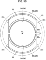
- the pair of ring segments 22 shown in FIG. 5B are obtained.
- the two planes S are planes parallel to a plane S0 (second plane) that includes the axis CL and is perpendicular to the side surface 21e of the ring mid-process body 21 (in other words, perpendicular to the aforementioned first plane), and are spaced from the plane S0 at an equal distance L (second distance).
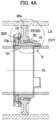
- the center vent tube CVT is inserted into the low pressure shaft LS, and is supported by the inner surface 12i of the inner wall portion 12 of the sleeve 10 of the support devices 1.
- each ring segment 22 when bringing the supporting surface of the ring segment 22 into contact with the inner surface of the main shaft at the time of assembly of the support device 1, each ring segment 22 only moves in the radial direction and does not deform. Additionally, even after assembly, since the supporting surface of the ring segment 22 is in close contact with the inner surface of the main shaft, there is no fear of deformation. Hence, the sleeve 10 placed between the ring segment 22 and the center vent tube CVT is also unlikely to deform.
Landscapes
- Engineering & Computer Science (AREA)
- Mechanical Engineering (AREA)
- General Engineering & Computer Science (AREA)
- Chemical & Material Sciences (AREA)
- Combustion & Propulsion (AREA)
- Structures Of Non-Positive Displacement Pumps (AREA)
Claims (1)
- Turbofan-Triebwerk (TF), umfassend eine hohle Niederdruckwelle (LS) und eine Stützvorrichtung (1) zum Stützen eines zentralen Entlüftungsrohrs (CVT) innerhalb der Niederdruckwelle (LS), wobei die Stützvorrichtung (1) umfasst:eine Hülse (10, 110);einen Ring (20), der aus einem Paar von Ringsegmenten (22, 122) gebildet und zwischen der Hülse (10) und der Niederdruckwelle (LS) angeordnet ist; undeine Ringmutter (30) zum axialen Fixieren der Ringsegmente (22, 122) an der Hülse (10, 110) und zum radialen Drücken der Ringsegmente (22, 122) gegen einen Innendurchmesser der Niederdruckwelle (LS), wobei:die Hülse (10, 110) einen Innenwandabschnitt (12), einen sich von einem vorderen Ende des Innenwandabschnitts (12) radial nach außen erstreckenden radialen Wandabschnitt (14, 114) und einen Außenwandabschnitt (16, 116) umfasst,der Innenwandabschnitt (12) eine Innenfläche (12i) und eine Außenfläche (12o) aufweist, die Innenfläche (12i) als zylindrische Fläche gebildet ist und mit einer Außenfläche des zentralen Entlüftungsrohrs (CVT) in Kontakt kommt, der radiale Wandabschnitt (14) eine teilweise abgeschnittene Ringform aufweist und ein Paar von Seitenflächen (14e) umfasst, die als Ebenen parallel zu einer ersten Ebene einschließlich einer Achse (CL) gebildet sind, deren Richtung mit der Richtung der Achse des Turbofan-Triebwerks (TF) übereinstimmt und von denen jede in einem ersten Abstand von der ersten Ebene beabstandet ist,die Mutter (30) eine Innenfläche (30i), die mit einem Gewindeabschnitt (30t) versehen ist, der mit einem Gewindeabschnitt (12t) ineinandergreift, der an der Außenfläche (12o) vorgesehen ist, und eine Außenfläche (30o) mit einer Druckfläche umfasst, die als konische Fläche gebildet ist, wobei die Innenfläche (30i) und die Außenfläche (30o) als im Wesentlichen zylindrische Flächen gebildet sind,jedes der Ringsegmente (22, 122) aus einem radial inneren zylindrischen Bohrungsabschnitt (24), einem radial äußeren zylindrischen Randabschnitt (26) und einem Stegabschnitt (28, 128) gebildet ist, der sich radial zwischen dem Bohrungsabschnitt (24) und dem Randabschnitt (26) erstreckt, um die Abschnitte (24, 26) zu verbinden, und eine Stützfläche umfasst, die durch mindestens einen Teil einer Außenfläche (26o) des Randabschnitts (26) als Teil einer zylindrischen Fläche mit einem Durchmesser gleich dem Innendurchmesser der Niederdruckwelle (LS) in einem Abschnitt, in dem die Stützvorrichtung (1) eingebaut werden soll, gebildet ist,eine Auflagefläche, die durch mindestens einen Teil einer Innenfläche (24i) des Bohrungsabschnitts (24) als Teil einer konischen Fläche mit einem Scheitelwinkel gebildet ist, der gleich dem der konischen Fläche ist, welche die Druckfläche bildet,ein Paar von Seitenflächen (22e), die als Ebenen parallel zu der ersten Ebene gebildet und jeweils von der ersten Ebene um den ersten Abstand beabstandet sind, undein Paar von Endflächen (22c), die als Ebenen gebildet sind, von denen jede von einer zweiten Ebene (S0) einschließlich der Achse (CL) und senkrecht zu der ersten Ebene in einem zweiten Abstand (L) beabstandet ist;dadurch gekennzeichnet, dass:der Außenwandabschnitt (16) der Hülse (10) von einer Außenkante des radialen Wandabschnitts (14) nach hinten vorsteht, wobei die Außenkante als zwei bogenförmige Abschnitte gebildet ist und der Außenwandabschnitt (16) aus zwei bogenförmigen Teilen gebildet ist, ein Außenloch (16a) den Außenwandabschnitt (16) radial durchdringt, das Außenloch (16a) in einem Umfangsmittelabschnitt des Außenwandabschnitts (16) vorgesehen und auf der gleichen Achse wie ein Innenloch (12a) gebildet ist, wobei das Innenloch (12a) den Innenwandabschnitt (12) und den radialen Wandabschnitt (14) der Hülse (10) überspannt und durchdringt,ein Positionierungsstift (10p) in das Innenloch (12a) eingepresst ist, ein Ausschnitt (24Fn), der den Positionierungsstift (10p) aufnimmt, in einem der Ringsegmente (22) vorgesehen ist oder ein Positionierungsstift (110p) in ein Axialloch (128a) eingepresst ist, das den Stegabschnitt (128) des Ringsegments (122) axial durchdringt, und in einem nach vorne vorstehenden Zustand fixiert ist, und ein Ausschnitt (116n), der den radialen Wandabschnitt (114) und den Außenwandabschnitt (116) radial durchdringt, während er diese überspannt, in einem Umfangsmittelabschnitt der Hülse (110) vorgesehen ist, wobeiin einem Zustand, in dem eine Vorderfläche des Bohrungsabschnitts (24) von jedem der Ringsegmente (22) mit dem radialen Wandabschnitt (14) der Hülse (10) in Kontakt kommt, der Positionierungsstift (10p) und der Ausschnitt (24Fn) in Beziehung zueinander wirken, um eine Relativbewegung der Hülse (10) und der Ringsegmente (22) in der Umfangsrichtung zu begrenzen und die Seitenflächen (14e) des radialen Wandabschnitts (14) der Hülse (10) und die Seitenflächen (22e) des Ringsegments (22) parallel zueinander zu halten,wobei die Druckfläche der Mutter (30) eingerichtet ist, die Auflagefläche des Ringsegments (22) nach oben und radial nach außen zu drücken, wenn die Mutter (30) mit der Druckfläche der Mutter (30) und der Auflagefläche des Ringsegments (22) in Kontakt miteinander auf die Hülse (10) vorwärtsgeschraubt wird, wobeidie Niederdruckwelle (LS) in der Nähe ihres hinteren Endes einen Abschnitt mit kleinem Durchmesser (SD) aufweist, der den Abschnitt mit dem kleinsten Durchmesser der Niederdruckwelle (LS) darstellt, dessen Innendurchmesser kleiner ist als derjenige der Position, an der die Stützvorrichtung (1) anzuordnen ist, und wobeidie teilweise abgeschnittene Ringform des radialen Wandabschnitts (14) der Hülse (10) und des Paars von Ringsegmenten (22) derart eingerichtet sind, dass in einem Anordnungszustand, in dem die Endflächen (22c) des Paars von Ringsegmenten (22) miteinander in Kontakt gebracht sind und ein Verbindungsring (20R) um eine Außenfläche des Bohrungsabschnitts (24) des Paars von Ringsegmenten (22) vorgesehen ist;ein Durchmesser eines Kreises, der eine projizierte Form der Stützvorrichtung (1) in einer Richtung senkrecht zu der zweiten Ebene (S0) umschreibt, kleiner ist als der Innendurchmesser der Niederdruckwelle (LS) an dem Abschnitt mit kleinem Durchmesser (SD).
Applications Claiming Priority (2)
| Application Number | Priority Date | Filing Date | Title |
|---|---|---|---|
| JP2017192744 | 2017-10-02 | ||
| PCT/JP2018/035769 WO2019069769A1 (ja) | 2017-10-02 | 2018-09-26 | ターボファンエンジンのセンターベントチューブ支持装置 |
Publications (3)
| Publication Number | Publication Date |
|---|---|
| EP3693559A1 EP3693559A1 (de) | 2020-08-12 |
| EP3693559A4 EP3693559A4 (de) | 2021-01-27 |
| EP3693559B1 true EP3693559B1 (de) | 2025-06-25 |
Family
ID=65995059
Family Applications (1)
| Application Number | Title | Priority Date | Filing Date |
|---|---|---|---|
| EP18863980.1A Active EP3693559B1 (de) | 2017-10-02 | 2018-09-26 | Stützvorrichtung für ein zentrales entlüftungsrohr eines turbofantriebwerks |
Country Status (4)
| Country | Link |
|---|---|
| US (1) | US11248496B2 (de) |
| EP (1) | EP3693559B1 (de) |
| JP (1) | JP6864273B2 (de) |
| WO (1) | WO2019069769A1 (de) |
Families Citing this family (1)
| Publication number | Priority date | Publication date | Assignee | Title |
|---|---|---|---|---|
| JP7426859B2 (ja) * | 2020-03-12 | 2024-02-02 | 本田技研工業株式会社 | 接合用支持治具 |
Family Cites Families (11)
| Publication number | Priority date | Publication date | Assignee | Title |
|---|---|---|---|---|
| US5205189A (en) * | 1990-12-17 | 1993-04-27 | General Electric Company | Engine shaft balance assembly |
| FR2817289B1 (fr) * | 2000-11-30 | 2003-01-31 | Snecma Moteurs | Dispositif de centrage d'un tube dans un arbre de turbine |
| FR2926604B1 (fr) * | 2008-01-23 | 2010-03-26 | Snecma | Centrage d'une piece a l'interieur d'un arbre de rotor dans une turbomachine |
| FR2957973B1 (fr) * | 2010-03-26 | 2013-04-12 | Snecma | Tube de degazage d'un turboreacteur, procede de montage d'un tel tube et turboreacteur avec un tel tube |
| CN202926472U (zh) * | 2012-11-15 | 2013-05-08 | 中航商用航空发动机有限责任公司 | 涡轮机轴内管平衡定心装置 |
| FR3007788B1 (fr) * | 2013-06-28 | 2015-07-24 | Snecma | Systeme d'accouplement ameliore d'un arbre de turbine a un tube de degazage de turbomachine |
| FR3008135B1 (fr) * | 2013-07-08 | 2017-05-26 | Snecma | Centrage d'une piece a l'interieur d'un arbre de rotor dans une turbomachine |
| JP6215740B2 (ja) * | 2014-03-14 | 2017-10-18 | 本田技研工業株式会社 | 部品の締結構造 |
| EP2933432A1 (de) * | 2014-04-15 | 2015-10-21 | Siemens Aktiengesellschaft | Rotor mit axial gesichertem Stützring |
| EP3176407B1 (de) | 2014-11-14 | 2019-05-15 | IHI Corporation | Triebwerk |
| JP6455179B2 (ja) * | 2015-01-26 | 2019-01-23 | 株式会社Ihi | センターベントチューブ調芯機構及びセンターベントチューブ支持装置 |
-
2018
- 2018-09-26 EP EP18863980.1A patent/EP3693559B1/de active Active
- 2018-09-26 JP JP2019546655A patent/JP6864273B2/ja active Active
- 2018-09-26 WO PCT/JP2018/035769 patent/WO2019069769A1/ja not_active Ceased
-
2020
- 2020-03-06 US US16/810,922 patent/US11248496B2/en active Active
Also Published As
| Publication number | Publication date |
|---|---|
| EP3693559A1 (de) | 2020-08-12 |
| WO2019069769A1 (ja) | 2019-04-11 |
| US11248496B2 (en) | 2022-02-15 |
| JPWO2019069769A1 (ja) | 2020-01-23 |
| JP6864273B2 (ja) | 2021-04-28 |
| EP3693559A4 (de) | 2021-01-27 |
| US20200208539A1 (en) | 2020-07-02 |
Similar Documents
| Publication | Publication Date | Title |
|---|---|---|
| EP2157289B1 (de) | Öldichtung mit pumpenden Laufrad | |
| US7458202B2 (en) | Lubrication system for a counter-rotating turbine engine and method of assembling same | |
| US7296398B2 (en) | Counter-rotating turbine engine and method of assembling same | |
| CA2659823C (en) | Thrust bearing housing for a gas turbine engine | |
| EP3719266B1 (de) | Anordnung für eine lagerkammer eines gasturbinentriebwerks | |
| EP2855892B1 (de) | Zwischengehäuse einer gasturbine welche eine dichtungsfläche beinhaltet | |
| EP3045668A1 (de) | Kühlkanäle für einen mittelturbinenrahmen | |
| CA2958347A1 (en) | Intermittent spigot joint for gas turbine engine casing connection | |
| EP3093431A1 (de) | Zwischenwellenintegrierte dichtungs- und kontermutter | |
| EP3070273A1 (de) | Kühlkanäle für einen mittelturbinenrahmen eines gasturbinentriebwerks | |
| US9022741B2 (en) | System for securing two tubular components one in the other, carrying a roller bearing | |
| EP2971820B1 (de) | Mit einer rinne und einem oder mehreren fluidpfaden konfiguriertes wälzlager | |
| EP3045669B1 (de) | Kühlkanäle für einen mittelturbinenrahmen | |
| EP1087101B1 (de) | Kopplunszusammenbau und Verfahren zur Befestigung von Luftleitungen in Gasturbinenrotoren | |
| US11248496B2 (en) | Center vent tube support device of turbofan engine | |
| US9957799B2 (en) | Balance ring for gas turbine engine | |
| EP3524783B1 (de) | Dichtungsträger für flugzeugtriebwerke mit verdrehsicherung | |
| EP3401562B1 (de) | Lager mit ungleichmässigem käfigspiel | |
| EP4012162B1 (de) | Drehhülse zur steuerung des spiels einer dichtungsanordnung einer gasturbine | |
| US10138940B2 (en) | Roller bearing cage for use in a gearbox | |
| US9644487B2 (en) | Fixed turbine engine receiver part comprising an assembly for holding ancillary systems in position inside a fixed hollow shaft | |
| EP3054090B1 (de) | Gasturbinenmotoren mit intern gestreckten zugwellen |
Legal Events
| Date | Code | Title | Description |
|---|---|---|---|
| STAA | Information on the status of an ep patent application or granted ep patent |
Free format text: STATUS: THE INTERNATIONAL PUBLICATION HAS BEEN MADE |
|
| PUAI | Public reference made under article 153(3) epc to a published international application that has entered the european phase |
Free format text: ORIGINAL CODE: 0009012 |
|
| STAA | Information on the status of an ep patent application or granted ep patent |
Free format text: STATUS: REQUEST FOR EXAMINATION WAS MADE |
|
| 17P | Request for examination filed |
Effective date: 20200402 |
|
| AK | Designated contracting states |
Kind code of ref document: A1 Designated state(s): AL AT BE BG CH CY CZ DE DK EE ES FI FR GB GR HR HU IE IS IT LI LT LU LV MC MK MT NL NO PL PT RO RS SE SI SK SM TR |
|
| AX | Request for extension of the european patent |
Extension state: BA ME |
|
| DAV | Request for validation of the european patent (deleted) | ||
| DAX | Request for extension of the european patent (deleted) | ||
| A4 | Supplementary search report drawn up and despatched |
Effective date: 20210113 |
|
| RIC1 | Information provided on ipc code assigned before grant |
Ipc: F02C 7/00 20060101ALI20201222BHEP Ipc: F01D 25/00 20060101AFI20201222BHEP Ipc: F01D 5/02 20060101ALI20201222BHEP |
|
| STAA | Information on the status of an ep patent application or granted ep patent |
Free format text: STATUS: EXAMINATION IS IN PROGRESS |
|
| 17Q | First examination report despatched |
Effective date: 20221221 |
|
| GRAP | Despatch of communication of intention to grant a patent |
Free format text: ORIGINAL CODE: EPIDOSNIGR1 |
|
| STAA | Information on the status of an ep patent application or granted ep patent |
Free format text: STATUS: GRANT OF PATENT IS INTENDED |
|
| INTG | Intention to grant announced |
Effective date: 20250319 |
|
| GRAS | Grant fee paid |
Free format text: ORIGINAL CODE: EPIDOSNIGR3 |
|
| GRAA | (expected) grant |
Free format text: ORIGINAL CODE: 0009210 |
|
| STAA | Information on the status of an ep patent application or granted ep patent |
Free format text: STATUS: THE PATENT HAS BEEN GRANTED |
|
| AK | Designated contracting states |
Kind code of ref document: B1 Designated state(s): AL AT BE BG CH CY CZ DE DK EE ES FI FR GB GR HR HU IE IS IT LI LT LU LV MC MK MT NL NO PL PT RO RS SE SI SK SM TR |
|
| REG | Reference to a national code |
Ref country code: GB Ref legal event code: FG4D |
|
| REG | Reference to a national code |
Ref country code: CH Ref legal event code: EP |
|
| REG | Reference to a national code |
Ref country code: DE Ref legal event code: R096 Ref document number: 602018083001 Country of ref document: DE |
|
| REG | Reference to a national code |
Ref country code: CH Ref legal event code: EP |
|
| REG | Reference to a national code |
Ref country code: IE Ref legal event code: FG4D |
|
| PG25 | Lapsed in a contracting state [announced via postgrant information from national office to epo] |
Ref country code: FI Free format text: LAPSE BECAUSE OF FAILURE TO SUBMIT A TRANSLATION OF THE DESCRIPTION OR TO PAY THE FEE WITHIN THE PRESCRIBED TIME-LIMIT Effective date: 20250625 |
|
| REG | Reference to a national code |
Ref country code: LT Ref legal event code: MG9D |
|
| PG25 | Lapsed in a contracting state [announced via postgrant information from national office to epo] |
Ref country code: NO Free format text: LAPSE BECAUSE OF FAILURE TO SUBMIT A TRANSLATION OF THE DESCRIPTION OR TO PAY THE FEE WITHIN THE PRESCRIBED TIME-LIMIT Effective date: 20250925 Ref country code: GR Free format text: LAPSE BECAUSE OF FAILURE TO SUBMIT A TRANSLATION OF THE DESCRIPTION OR TO PAY THE FEE WITHIN THE PRESCRIBED TIME-LIMIT Effective date: 20250926 |
|
| PG25 | Lapsed in a contracting state [announced via postgrant information from national office to epo] |
Ref country code: BG Free format text: LAPSE BECAUSE OF FAILURE TO SUBMIT A TRANSLATION OF THE DESCRIPTION OR TO PAY THE FEE WITHIN THE PRESCRIBED TIME-LIMIT Effective date: 20250625 |
|
| PG25 | Lapsed in a contracting state [announced via postgrant information from national office to epo] |
Ref country code: HR Free format text: LAPSE BECAUSE OF FAILURE TO SUBMIT A TRANSLATION OF THE DESCRIPTION OR TO PAY THE FEE WITHIN THE PRESCRIBED TIME-LIMIT Effective date: 20250625 |
|
| PGFP | Annual fee paid to national office [announced via postgrant information from national office to epo] |
Ref country code: FR Payment date: 20250924 Year of fee payment: 8 |
|
| PG25 | Lapsed in a contracting state [announced via postgrant information from national office to epo] |
Ref country code: RS Free format text: LAPSE BECAUSE OF FAILURE TO SUBMIT A TRANSLATION OF THE DESCRIPTION OR TO PAY THE FEE WITHIN THE PRESCRIBED TIME-LIMIT Effective date: 20250925 |
|
| PG25 | Lapsed in a contracting state [announced via postgrant information from national office to epo] |
Ref country code: LV Free format text: LAPSE BECAUSE OF FAILURE TO SUBMIT A TRANSLATION OF THE DESCRIPTION OR TO PAY THE FEE WITHIN THE PRESCRIBED TIME-LIMIT Effective date: 20250625 |
|
| REG | Reference to a national code |
Ref country code: NL Ref legal event code: MP Effective date: 20250625 |
|
| PG25 | Lapsed in a contracting state [announced via postgrant information from national office to epo] |
Ref country code: NL Free format text: LAPSE BECAUSE OF FAILURE TO SUBMIT A TRANSLATION OF THE DESCRIPTION OR TO PAY THE FEE WITHIN THE PRESCRIBED TIME-LIMIT Effective date: 20250625 |
|
| PG25 | Lapsed in a contracting state [announced via postgrant information from national office to epo] |
Ref country code: PT Free format text: LAPSE BECAUSE OF FAILURE TO SUBMIT A TRANSLATION OF THE DESCRIPTION OR TO PAY THE FEE WITHIN THE PRESCRIBED TIME-LIMIT Effective date: 20251027 |
|
| REG | Reference to a national code |
Ref country code: AT Ref legal event code: MK05 Ref document number: 1806633 Country of ref document: AT Kind code of ref document: T Effective date: 20250625 |
|
| PG25 | Lapsed in a contracting state [announced via postgrant information from national office to epo] |
Ref country code: IS Free format text: LAPSE BECAUSE OF FAILURE TO SUBMIT A TRANSLATION OF THE DESCRIPTION OR TO PAY THE FEE WITHIN THE PRESCRIBED TIME-LIMIT Effective date: 20251025 |
|
| PG25 | Lapsed in a contracting state [announced via postgrant information from national office to epo] |
Ref country code: AT Free format text: LAPSE BECAUSE OF FAILURE TO SUBMIT A TRANSLATION OF THE DESCRIPTION OR TO PAY THE FEE WITHIN THE PRESCRIBED TIME-LIMIT Effective date: 20250625 Ref country code: SM Free format text: LAPSE BECAUSE OF FAILURE TO SUBMIT A TRANSLATION OF THE DESCRIPTION OR TO PAY THE FEE WITHIN THE PRESCRIBED TIME-LIMIT Effective date: 20250625 |
|
| PG25 | Lapsed in a contracting state [announced via postgrant information from national office to epo] |
Ref country code: CZ Free format text: LAPSE BECAUSE OF FAILURE TO SUBMIT A TRANSLATION OF THE DESCRIPTION OR TO PAY THE FEE WITHIN THE PRESCRIBED TIME-LIMIT Effective date: 20250625 |
|
| PG25 | Lapsed in a contracting state [announced via postgrant information from national office to epo] |
Ref country code: PL Free format text: LAPSE BECAUSE OF FAILURE TO SUBMIT A TRANSLATION OF THE DESCRIPTION OR TO PAY THE FEE WITHIN THE PRESCRIBED TIME-LIMIT Effective date: 20250625 |
|
| PG25 | Lapsed in a contracting state [announced via postgrant information from national office to epo] |
Ref country code: EE Free format text: LAPSE BECAUSE OF FAILURE TO SUBMIT A TRANSLATION OF THE DESCRIPTION OR TO PAY THE FEE WITHIN THE PRESCRIBED TIME-LIMIT Effective date: 20250625 |
|
| PG25 | Lapsed in a contracting state [announced via postgrant information from national office to epo] |
Ref country code: SK Free format text: LAPSE BECAUSE OF FAILURE TO SUBMIT A TRANSLATION OF THE DESCRIPTION OR TO PAY THE FEE WITHIN THE PRESCRIBED TIME-LIMIT Effective date: 20250625 |
|
| PG25 | Lapsed in a contracting state [announced via postgrant information from national office to epo] |
Ref country code: ES Free format text: LAPSE BECAUSE OF FAILURE TO SUBMIT A TRANSLATION OF THE DESCRIPTION OR TO PAY THE FEE WITHIN THE PRESCRIBED TIME-LIMIT Effective date: 20250625 |
|
| PG25 | Lapsed in a contracting state [announced via postgrant information from national office to epo] |
Ref country code: RO Free format text: LAPSE BECAUSE OF FAILURE TO SUBMIT A TRANSLATION OF THE DESCRIPTION OR TO PAY THE FEE WITHIN THE PRESCRIBED TIME-LIMIT Effective date: 20250625 |
|
| PG25 | Lapsed in a contracting state [announced via postgrant information from national office to epo] |
Ref country code: DK Free format text: LAPSE BECAUSE OF FAILURE TO SUBMIT A TRANSLATION OF THE DESCRIPTION OR TO PAY THE FEE WITHIN THE PRESCRIBED TIME-LIMIT Effective date: 20250625 |
|
| PG25 | Lapsed in a contracting state [announced via postgrant information from national office to epo] |
Ref country code: IT Free format text: LAPSE BECAUSE OF FAILURE TO SUBMIT A TRANSLATION OF THE DESCRIPTION OR TO PAY THE FEE WITHIN THE PRESCRIBED TIME-LIMIT Effective date: 20250625 |
|
| PLBE | No opposition filed within time limit |
Free format text: ORIGINAL CODE: 0009261 |
|
| STAA | Information on the status of an ep patent application or granted ep patent |
Free format text: STATUS: NO OPPOSITION FILED WITHIN TIME LIMIT |
|
| REG | Reference to a national code |
Ref country code: CH Ref legal event code: H13 Free format text: ST27 STATUS EVENT CODE: U-0-0-H10-H13 (AS PROVIDED BY THE NATIONAL OFFICE) Effective date: 20260504 |
|
| REG | Reference to a national code |
Ref country code: CH Ref legal event code: L10 Free format text: ST27 STATUS EVENT CODE: U-0-0-L10-L00 (AS PROVIDED BY THE NATIONAL OFFICE) Effective date: 20260507 |