EP3693553A1 - Feather seal assembly with leakage metering - Google Patents
Feather seal assembly with leakage metering Download PDFInfo
- Publication number
- EP3693553A1 EP3693553A1 EP20155234.6A EP20155234A EP3693553A1 EP 3693553 A1 EP3693553 A1 EP 3693553A1 EP 20155234 A EP20155234 A EP 20155234A EP 3693553 A1 EP3693553 A1 EP 3693553A1
- Authority
- EP
- European Patent Office
- Prior art keywords
- seal
- cooling hole
- feather seal
- feather
- cooling
- Prior art date
- Legal status (The legal status is an assumption and is not a legal conclusion. Google has not performed a legal analysis and makes no representation as to the accuracy of the status listed.)
- Granted
Links
Images



Classifications
-
- F—MECHANICAL ENGINEERING; LIGHTING; HEATING; WEAPONS; BLASTING
- F01—MACHINES OR ENGINES IN GENERAL; ENGINE PLANTS IN GENERAL; STEAM ENGINES
- F01D—NON-POSITIVE DISPLACEMENT MACHINES OR ENGINES, e.g. STEAM TURBINES
- F01D11/00—Preventing or minimising internal leakage of working-fluid, e.g. between stages
- F01D11/005—Sealing means between non relatively rotating elements
- F01D11/006—Sealing the gap between rotor blades or blades and rotor
-
- F—MECHANICAL ENGINEERING; LIGHTING; HEATING; WEAPONS; BLASTING
- F01—MACHINES OR ENGINES IN GENERAL; ENGINE PLANTS IN GENERAL; STEAM ENGINES
- F01D—NON-POSITIVE DISPLACEMENT MACHINES OR ENGINES, e.g. STEAM TURBINES
- F01D5/00—Blades; Blade-carrying members; Heating, heat-insulating, cooling or antivibration means on the blades or the members
- F01D5/12—Blades
- F01D5/14—Form or construction
- F01D5/18—Hollow blades, i.e. blades with cooling or heating channels or cavities; Heating, heat-insulating or cooling means on blades
- F01D5/187—Convection cooling
-
- F—MECHANICAL ENGINEERING; LIGHTING; HEATING; WEAPONS; BLASTING
- F01—MACHINES OR ENGINES IN GENERAL; ENGINE PLANTS IN GENERAL; STEAM ENGINES
- F01D—NON-POSITIVE DISPLACEMENT MACHINES OR ENGINES, e.g. STEAM TURBINES
- F01D11/00—Preventing or minimising internal leakage of working-fluid, e.g. between stages
- F01D11/02—Preventing or minimising internal leakage of working-fluid, e.g. between stages by non-contact sealings, e.g. of labyrinth type
- F01D11/04—Preventing or minimising internal leakage of working-fluid, e.g. between stages by non-contact sealings, e.g. of labyrinth type using sealing fluid, e.g. steam
- F01D11/06—Control thereof
-
- F—MECHANICAL ENGINEERING; LIGHTING; HEATING; WEAPONS; BLASTING
- F01—MACHINES OR ENGINES IN GENERAL; ENGINE PLANTS IN GENERAL; STEAM ENGINES
- F01D—NON-POSITIVE DISPLACEMENT MACHINES OR ENGINES, e.g. STEAM TURBINES
- F01D25/00—Component parts, details, or accessories, not provided for in, or of interest apart from, other groups
- F01D25/08—Cooling; Heating; Heat-insulation
-
- F—MECHANICAL ENGINEERING; LIGHTING; HEATING; WEAPONS; BLASTING
- F01—MACHINES OR ENGINES IN GENERAL; ENGINE PLANTS IN GENERAL; STEAM ENGINES
- F01D—NON-POSITIVE DISPLACEMENT MACHINES OR ENGINES, e.g. STEAM TURBINES
- F01D9/00—Stators
- F01D9/06—Fluid supply conduits to nozzles or the like
- F01D9/065—Fluid supply or removal conduits traversing the working fluid flow, e.g. for lubrication-, cooling-, or sealing fluids
-
- F—MECHANICAL ENGINEERING; LIGHTING; HEATING; WEAPONS; BLASTING
- F05—INDEXING SCHEMES RELATING TO ENGINES OR PUMPS IN VARIOUS SUBCLASSES OF CLASSES F01-F04
- F05D—INDEXING SCHEME FOR ASPECTS RELATING TO NON-POSITIVE-DISPLACEMENT MACHINES OR ENGINES, GAS-TURBINES OR JET-PROPULSION PLANTS
- F05D2230/00—Manufacture
- F05D2230/50—Building or constructing in particular ways
- F05D2230/54—Building or constructing in particular ways by sheet metal manufacturing
-
- F—MECHANICAL ENGINEERING; LIGHTING; HEATING; WEAPONS; BLASTING
- F05—INDEXING SCHEMES RELATING TO ENGINES OR PUMPS IN VARIOUS SUBCLASSES OF CLASSES F01-F04
- F05D—INDEXING SCHEME FOR ASPECTS RELATING TO NON-POSITIVE-DISPLACEMENT MACHINES OR ENGINES, GAS-TURBINES OR JET-PROPULSION PLANTS
- F05D2240/00—Components
- F05D2240/10—Stators
- F05D2240/12—Fluid guiding means, e.g. vanes
-
- F—MECHANICAL ENGINEERING; LIGHTING; HEATING; WEAPONS; BLASTING
- F05—INDEXING SCHEMES RELATING TO ENGINES OR PUMPS IN VARIOUS SUBCLASSES OF CLASSES F01-F04
- F05D—INDEXING SCHEME FOR ASPECTS RELATING TO NON-POSITIVE-DISPLACEMENT MACHINES OR ENGINES, GAS-TURBINES OR JET-PROPULSION PLANTS
- F05D2240/00—Components
- F05D2240/55—Seals
- F05D2240/57—Leaf seals
-
- F—MECHANICAL ENGINEERING; LIGHTING; HEATING; WEAPONS; BLASTING
- F05—INDEXING SCHEMES RELATING TO ENGINES OR PUMPS IN VARIOUS SUBCLASSES OF CLASSES F01-F04
- F05D—INDEXING SCHEME FOR ASPECTS RELATING TO NON-POSITIVE-DISPLACEMENT MACHINES OR ENGINES, GAS-TURBINES OR JET-PROPULSION PLANTS
- F05D2250/00—Geometry
- F05D2250/10—Two-dimensional
- F05D2250/19—Two-dimensional machined; miscellaneous
- F05D2250/191—Two-dimensional machined; miscellaneous perforated
-
- F—MECHANICAL ENGINEERING; LIGHTING; HEATING; WEAPONS; BLASTING
- F05—INDEXING SCHEMES RELATING TO ENGINES OR PUMPS IN VARIOUS SUBCLASSES OF CLASSES F01-F04
- F05D—INDEXING SCHEME FOR ASPECTS RELATING TO NON-POSITIVE-DISPLACEMENT MACHINES OR ENGINES, GAS-TURBINES OR JET-PROPULSION PLANTS
- F05D2250/00—Geometry
- F05D2250/20—Three-dimensional
- F05D2250/29—Three-dimensional machined; miscellaneous
-
- F—MECHANICAL ENGINEERING; LIGHTING; HEATING; WEAPONS; BLASTING
- F05—INDEXING SCHEMES RELATING TO ENGINES OR PUMPS IN VARIOUS SUBCLASSES OF CLASSES F01-F04
- F05D—INDEXING SCHEME FOR ASPECTS RELATING TO NON-POSITIVE-DISPLACEMENT MACHINES OR ENGINES, GAS-TURBINES OR JET-PROPULSION PLANTS
- F05D2250/00—Geometry
- F05D2250/20—Three-dimensional
- F05D2250/29—Three-dimensional machined; miscellaneous
- F05D2250/294—Three-dimensional machined; miscellaneous grooved
-
- F—MECHANICAL ENGINEERING; LIGHTING; HEATING; WEAPONS; BLASTING
- F05—INDEXING SCHEMES RELATING TO ENGINES OR PUMPS IN VARIOUS SUBCLASSES OF CLASSES F01-F04
- F05D—INDEXING SCHEME FOR ASPECTS RELATING TO NON-POSITIVE-DISPLACEMENT MACHINES OR ENGINES, GAS-TURBINES OR JET-PROPULSION PLANTS
- F05D2250/00—Geometry
- F05D2250/30—Arrangement of components
- F05D2250/31—Arrangement of components according to the direction of their main axis or their axis of rotation
- F05D2250/313—Arrangement of components according to the direction of their main axis or their axis of rotation the axes being perpendicular to each other
-
- F—MECHANICAL ENGINEERING; LIGHTING; HEATING; WEAPONS; BLASTING
- F05—INDEXING SCHEMES RELATING TO ENGINES OR PUMPS IN VARIOUS SUBCLASSES OF CLASSES F01-F04
- F05D—INDEXING SCHEME FOR ASPECTS RELATING TO NON-POSITIVE-DISPLACEMENT MACHINES OR ENGINES, GAS-TURBINES OR JET-PROPULSION PLANTS
- F05D2250/00—Geometry
- F05D2250/70—Shape
- F05D2250/75—Shape given by its similarity to a letter, e.g. T-shaped
Definitions
- the present disclosure relates to gas turbine engines, and in particular, to an intersegment seal assembly.
- Feather seals are commonly used in aerospace and other industries to provide a seal between two adjacent components.
- gas turbine engine vanes are arranged in a circumferential configuration to form an annular vane ring assembly about a center axis of the gas turbine engine.
- each stator segment includes an airfoil and a platform section. When assembled, the platforms abut and define a radially inner and radially outer boundary to a core flow path.
- each platform includes a channel which receives a feather seal assembly that seals the hot gas core flow from a surrounding medium, such as a cooling airflow.
- a feather seal assembly that seals the hot gas core flow from a surrounding medium, such as a cooling airflow.
- the edges of the platform that are exposed to the hot gas core flow require cooling to reduce wear and corrosion.
- cooling holes have been formed in the edges of the platform that direct cooling air from a passage inside the vane to the edges. These cooling holes can be difficult and expensive to form.
- an assembly for a gas turbine engine that includes a first component and a second component adjacent to the first component.
- the first component and the second component each include a body having two circumferential sides, a leading end, and a trailing end.
- One of the circumferential sides of the first component is adjacent one of the circumferential sides of the second component, and the circumferential sides each include a seal channel.
- a first feather seal is inside the seal channel between the first component and the second component and includes first cooling hole extending through the first feather seal.
- a second feather seal is inside the seal channel between the first component and the second component and is adjacent to the first feather seal.
- the second feather seal includes a second cooling hole extending through the second feather seal.
- the first cooling hole is positioned over at least a portion of the second cooling hole.
- the assembly of the preceding paragraph can optionally include, additionally and/or alternatively, any one or more of the following features, configurations and/or additional components:
- a seal assembly in accordance with a second aspect of the disclosure, includes a first feather seal with a first cooling hole extending through the first feather seal.
- the seal assembly also includes a second feather seal adjacent to the first feather seal.
- the second feather seal includes a second cooling hole extending through the second feather seal.
- the first cooling hole is positioned over at least a portion of the second cooling hole.
- seal assembly of the preceding paragraph can optionally include, additionally and/or alternatively, any one or more of the following features, configurations and/or additional components:
- a seal assembly for a gas turbine engine includes a first feather seal with a first cooling hole extending through the first feather seal.
- the seal assembly also includes a second feather seal adjacent to the first feather seal.
- the second feather seal includes a second cooling hole extending through the second feather seal.
- the first cooling hole extends over at least a portion of the second cooling hole, and a perimeter of the first cooling hole is larger than a perimeter of the second cooling hole.
- seal assembly of the preceding paragraph can optionally include, additionally and/or alternatively, any one or more of the following features, configurations and/or additional components:
- the seal assembly includes two feather seals stacked together.
- the first feather seal includes a first cooling hole
- the second feather seal includes a second cooling hole.
- the first cooling hole extends over at least a portion of the second cooling hole to provide a cooling air pathway across the seal assembly.
- the geometry and/or orientation of the first cooling hole is different from the second cooling hole such that the cooling air pathway across the seal assembly is not restricted or closed should the first feather seal shift relative the second feather seal.
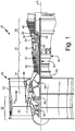
- FIG. 1 is a quarter-sectional view that schematically illustrates example gas turbine engine 20 that includes fan section 22, compressor section 24, combustor section 26 and turbine section 28.
- Alternative engines might include an augmenter section (not shown) among other systems or features.
- Fan section 22 drives air along bypass flowpath B while compressor section 24 draws air in along core flowpath C where air is compressed and communicated to combustor section 26.
- combustor section 26 air is mixed with fuel and ignited to generate a high pressure exhaust gas stream that expands through turbine section 28 where energy is extracted and utilized to drive fan section 22 and compressor section 24.
- turbofan gas turbine engine depicts a turbofan gas turbine engine
- concepts described herein are not limited to use with turbofans as the teachings may be applied to other types of turbine engines; for example, an industrial gas turbine; a reverse-flow gas turbine engine; and a turbine engine including a three-spool architecture in which three spools concentrically rotate about a common axis and where a low spool enables a low pressure turbine to drive a fan via a gearbox, an intermediate spool that enables an intermediate pressure turbine to drive a first compressor of the compressor section, and a high spool that enables a high pressure turbine to drive a high pressure compressor of the compressor section.
- the example gas turbine engine 20 generally includes low speed spool 30 and high speed spool 32 mounted for rotation about center axis A of gas turbine engine 20 relative to engine static structure 36 via several bearing systems 38. It should be understood that various bearing systems 38 at various locations may alternatively or additionally be provided.
- Low speed spool 30 generally includes inner shaft 40 that connects fan 42 and low pressure (or first) compressor section 44 to low pressure (or first) turbine section 46.
- Inner shaft 40 drives fan 42 through a speed change device, such as geared architecture 48, to drive fan 42 at a lower speed than low speed spool 30.
- High-speed spool 32 includes outer shaft 50 that interconnects high pressure (or second) compressor section 52 and high pressure (or second) turbine section 54.
- Inner shaft 40 and outer shaft 50 are concentric and rotate via bearing systems 38 about center axis A.
- Combustor 56 is arranged between high pressure compressor 52 and high pressure turbine 54.
- high pressure turbine 54 includes at least two stages to provide double stage high pressure turbine 54.
- high pressure turbine 54 includes only a single stage.
- a "high pressure" compressor or turbine experiences a higher pressure than a corresponding "low pressure” compressor or turbine.
- the example low pressure turbine 46 has a pressure ratio that is greater than about 5.
- the pressure ratio of the example low pressure turbine 46 is measured prior to an inlet of low pressure turbine 46 as related to the pressure measured at the outlet of low pressure turbine 46 prior to an exhaust nozzle.
- Mid-turbine frame 58 of engine static structure 36 can be arranged generally between high pressure turbine 54 and low pressure turbine 46.
- Mid-turbine frame 58 further supports bearing systems 38 in turbine section 28 as well as setting airflow entering the low pressure turbine 46.
- Mid-turbine frame 58 includes vanes 60, which are in the core flowpath and function as an inlet guide vane for low pressure turbine 46.
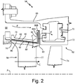
- FIG. 2 is a cross-sectional view of high pressure turbine section 54 with rotor assembly 62 and vane assembly 64.
- FIG. 3 is a perspective view of one segment of vane assembly 64.
- vane assembly 64 is positioned upstream from rotor assembly 62.
- Core casing 66 is disposed around both rotor assembly 62 and vane assembly 64 and is spaced radially from rotor assembly 62 and vane assembly 64 to form plenum 68.
- Cooling airflow F can be directed through plenum 68 to cool the components of high pressure turbine section 54. Cooling airflow F travels through plenum 68 at pressures higher than the pressure of the hot combustion gases in the core flowpath C.
- Rotor assembly 62 includes mounting structure 70, blade outer air seal (BOAS) 72, and turbine blades 74 (only one of which is shown in FIG. 2 ).
- Mounting structure 70 connects BOAS 72 to core casing 66 and spaces BOAS 72 relative turbine blades 74.
- BOAS 72 and mounting structure 70 are static components that do not rotate about center axis A.
- BOAS 72 forms an outer diameter endwall for the portion of core flowpath C in rotor assembly 62.
- BOAS 72 is cooled by cooling airflow F, thereby allowing BOAS 72 to withstand the high temperatures of the hot combustion gases exiting combustor 56 (shown in FIG. 1 ).
- BOAS 72 can be divided into a plurality of segments (only one of which is shown in FIG. 2 ) that are assembled into a ring that extends around center axis A.
- vane assembly 64 includes vane outer diameter (OD) platform 76 and at least one airfoil 77 extending from vane OD platform 76 toward center axis A.
- Vane OD platform 76 is positioned radially outward from center axis A and can be aligned with BOAS 72.
- Vane OD platform 76 is a static component that does not rotate about center axis A.
- Vane OD platform 76 forms the outer diameter flowpath across vane assembly 64 to direct combustion gases from combustor 56 to rotor assembly 62.
- Vane OD platform 76 and airfoils 77 are divided into a plurality of segments (only one of which is shown in FIGS. 2 and 3 ) that are assembled together to form an annular rind around center axis A. Each segment of vane OD platform 76 can be connected to one or more airfoils 77.
- Each segment of vane OD platform 76 includes leading end 78, aft end 80, two circumferential side surfaces 82 (only one of which is shown), aft rail 84, and channel 86.
- Channel 86 includes first branch 86A and second branch 86B.
- Seal assembly 88 is disposed in channel 86 and includes first feather seal 90 and second feather seal 92.
- First feather seal 90 includes axial portion 90A, radial portion 90B, and elbow 90C.
- Second feather seal 92 includes axial portion 92A, radial portion 92B, and elbow 90C.
- first feather seal 90 further includes first cooling hole 94
- second feather seal 92 includes additional cooling holes 96.
- Each segment of vane OD platform 76 extends axially from leading end 78 to aft end 80 and extends circumferentially between the circumferential side surfaces 82.
- Aft rail 84 extends radially outward from aft end 80 of vane OD platform 76.
- Channel 86 is formed on each of circumferential side surfaces 82. Channel 86 extends axially on circumferential side surface 82 from leading end 78 toward aft end 80. Proximate aft end 80, channel 86 splits into first branch 86A and second branch 86B. Both first branch 86A and second branch 86B of channel 86 extending radially outward on circumferential side surface 82 and aft rail 84.
- Second branch 86B is axially spaced from first branch 86A and is aft of first branch 86A so as to form gap 87 between first branch 86A and second branch 86B.
- Channel 86 extends circumferentially into vane OD platform to receive a portion of both first feather seal 90 and second feather seal 92.
- First feather seal 90 and second feather seal 92 are both thin strips of flat metal sheet.
- First feather seal 90 and second feather seal 92 can both be formed from cobalt alloy or any other metal or material capable of withstanding the high temperatures and stresses present in high pressure turbine section 54 during operation of gas turbine engine 20.
- First feather seal 90 is received in channel 86 such that axial portion 90A extends from leading end 78 to elbow 90C, and radial portion 90B extends radially outward from elbow 90C in first branch 86A.
- Second feather seal 92 is received in channel 86 such that axial portion 92A extends from leading end 78 to elbow 92C, and radial portion 92B extends radially outward from elbow 92C in second branch 86B of channel 86. As shown in both FIGS.
- axial portion 90A of first feather seal 90 abuts and is adjacent to axial portion 92A of second feather seal 92.
- Axial portion 90A of first feather seal 90 is radially outward of axial portion 92A of second feather seal 92 and covers most of axial portion 92A.
- Radial portion 92B and elbow 92C of second feather seal 92 are spaced axially aft of radial portion 90B and elbow 90C of first feather seal 90 with gap 87 being formed between radial portion 90B and radial portion 92B.
- first feather seal 90 and second feather seal 92 are received in channel 86 of the second segment to close the space between the two segments and prevent cooling airflow F from leaking uncontrolled between the two segments and into core flowpath C.
- radial portion 90B of first feather seal 90, gap 87 and radial portion 92B of second feather seal 92 provide an effective seal between the two segments at aft rail 84.
- First cooling hole 94 of first feather seal 90 and cooling holes 96 of second feather seal 92 do allow metered cooling flow across seal assembly 88 to cool the space between the two vane OD platform 76 segments that are exposed to core flowpath C. Cooling the space between the two OD platform 76 segments reduces thermal corrosion and damage to vane assembly 64 during engine operation and thereby increases the operating life of vane assembly 64.
- First cooling hole 94 of first feather seal 90 and cooling holes 96 of second feather seal 92 are discussed in detail below with reference to FIGS. 4A and 4B .
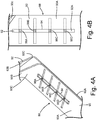
- FIG. 4A is a perspective view of the embodiment of seal assembly 88 from FIG. 3 .
- FIG. 4B is a top elevation view of seal assembly 88 from FIG. 4A .
- first cooling hole 94 is an elongated slot formed in axial portion 90A of first feather seal 90 and that extends axially relative center axis A (shown in FIG. 2 ).
- First cooling hole 94 as embodied in FIGS. 4A and 4B , is centered widthwise on axial portion 90A.
- Cooling holes 96 of second feather seal 92 include four cooling holes 96A, 96B, 96C, and 96D, with each of the four cooling holes 96A, 96B, 96C, and 96D being formed on axial portion 92A of feather seal 92.
- the four cooling holes 96A, 96B, 96C, and 96D are each an elongated slot that extends in the widthwise direction or circumferential direction relative center axis A (shown in FIG. 2 ) and orthogonal to first cooling hole 94.
- Each of the four cooling holes 96A, 96B, 96C, and 96D is individually shorter in length than first cooling hole 94 and has a smaller perimeter than first cooling hole 94.
- first cooling hole 94 is sufficiently long enough to extend over a portion of each of the four cooling holes 96A, 96B, 96C, and 96D.
- first cooling hole 94 and the four cooling holes 96A, 96B, 96C, and 96D are all elongated slots, the flow area through first cooling hole 94 and the four cooling holes 96A, 96B, 96C, and 96D does not change significantly should first feather seal 90 shift axially or circumferentially relative second feather seal 92 inside channel 86 (shown in FIGS. 2 and 3 ).
- cooling airflow F can flow through seal assembly 88 without choking regardless if first feather seal 90 or second feather seal 92 shifts circumferentially and/or axially within channel 86.
- FIGS. 5A-FIG. 10 show various additional embodiments of the cooling holes of first feather seal 90 and second feather seal 92.
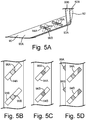
- first feather seal 90 includes two cooling holes 94A and 94B formed in axial portion 90A.
- Second feather seal 92 includes two cooling holes 96A and 96B. Cooling holes 94A, 94B, 96A, and 96B are all elongated slots. Cooling holes 94A and 94B of first feather seal 90 are non-parallel to cooling holes 96A and 96B of second feather seal 92. Cooling hole 94A is positioned over cooling hole 96A. Cooling hole 94B is positioned over cooling hole 96B.
- FIGS. 5A and 5B show first feather seal 90 in a nominal position over second feather seal 92. FIG.
- FIG. 5C shows first feather seal 90 shifted axially relative to second feather seal 92.
- FIG. 5D shows first feather seal 90 shifted circumferentially relative second feather seal 92. In each instance represented by FIGS. 5A-5D , the flow area across first feather seal 90 and second feather seal 92 does not decrease.
- FIGS. 6A and 6B show another embodiment of first feather seal 90 and second feather seal 92.
- first feather seal 90 includes two cooling holes 94A and 94B that are elongated axially-extending slots that are spaced widthwise from each other.
- Second feather seal 92 includes six cooling holes 96A-96F. Cooling holes 96A-96F are elongated slots that each have a length extending in the direction of the width of second feather seal 92.
- cooling hole 94A extends over a portion of each of cooling holes 96B, 96D, and 96F
- cooling hole 94B extends over a portion of each of cooling holes 96A, 96C, and 96E. Similar to the previously described embodiments of FIGS.
- first feather seal 90 shifts circumferentially or axially relative second feather seal 92, the flow area through holes 94A, 94B, and 96A-96F does not decrease.
- first feather seal 90 shift circumferentially such that cooling hole 94A is open to less of cooling holes 96B, 96D, and 96F, cooling hole 94B will shift over cooling holes 96B, 96D, and 96F to compensate while still maintaining the same flow area through cooling holes 96A, 96C, and 96E.
- FIG. 7 discloses an embodiment where cooling holes 94A-94C for first feather seal 90 are elongated slots that each have a length extending in the direction of the width of first feather seal 90. Cooling holes 96A-96C are circular holes that are positioned under cooling holes 94A-94C respectively.
- FIG. 8 discloses an embodiment where cooling holes 94a and 94B are elongated slots that each have a length extending in the direction of the width of first feather seal 90.
- Second feather seal 92 includes a first plurality of circular cooling holes 96A and a second plurality of circular cooling holes 96B spaced on second feather seal 92 from the first plurality of circular cooling holes 96A.
- Cooling hole 94A of first feather seal 90 is positioned over a portion of the first plurality of circular cooling holes 96A
- cooling hole 94B is positioned over a portion of the second plurality of circular cooling holes 96B.
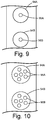
- FIG. 9 discloses an embodiment of first feather seal 90 with cooling holes 94A and 94B that are both circular cooling holes.
- Second feather seal 92 includes cooling holes 96A and 96B that are circular holes that are each smaller in diameter than cooling holes 94A and 94B respectively.
- Cooling holes 94A and 94B are sufficiently larger in diameter than cooling holes 96A and 96B that cooling holes 96A and 96B are always positioned within the perimeters of cooling holes 94A and 94b respectively in the event first feather seal 90 or second feather seal 92 shifts inside channel 86 (shown in FIGS. 2 and 3 ).
- FIG. 10 discloses an embodiment of first feather seal 90 with cooling holes 94A and 94B that are both circular cooling holes.
- Second feather seal 92 includes a first plurality of circular cooling holes 96A and a second plurality of circular cooling holes 96B spaced on second feather seal 92 from the first plurality of circular cooling holes 96A. All of the cooling holes 96A and 96B on second feather seal 92 are significantly smaller in diameter than cooling holes 94A and 94B of first feather seal 90.
- first feather seal 90 is positioned nominally over second feather seal 92
- cooling hole 94A is positioned over the entire first plurality of circular cooling holes 96A
- cooling hole 94B is positioned over the entire second plurality of circular cooling holes 96B.
- Cooling holes 94A and 94B are large enough in diameter that the entire first plurality of circular holes 96A and the entire second plurality of cooling holes 96B are always positioned within the perimeters of cooling holes 94A and 94B respectively in the event first feather seal 90 or second feather seal 92 shifts inside channel 86 (shown in FIGS. 2 and 3 ).
- any relative terms or terms of degree used herein such as “substantially”, “essentially”, “generally”, “approximately”, and the like, should be interpreted in accordance with and subject to any applicable definitions or limits expressly stated herein. In all instances, any relative terms or terms of degree used herein should be interpreted to broadly encompass any relevant disclosed embodiments as well as such ranges or variations as would be understood by a person of ordinary skill in the art in view of the entirety of the present disclosure, such as to encompass ordinary manufacturing tolerance variations, incidental alignment variations, transitory vibrations and sway movements, temporary alignment or shape variations induced by operational conditions, and the like.
- first feather seal 90 and second feather seal 92 can be used in BOAS 72.
- first feather seal 90 and second feather seal 92 can be used between platforms of two rotor blades.
Landscapes
- Engineering & Computer Science (AREA)
- Mechanical Engineering (AREA)
- General Engineering & Computer Science (AREA)
- Physics & Mathematics (AREA)
- Fluid Mechanics (AREA)
- Turbine Rotor Nozzle Sealing (AREA)
Abstract
Description
- The present disclosure relates to gas turbine engines, and in particular, to an intersegment seal assembly.
- Feather seals are commonly used in aerospace and other industries to provide a seal between two adjacent components. For example, gas turbine engine vanes are arranged in a circumferential configuration to form an annular vane ring assembly about a center axis of the gas turbine engine. Typically, each stator segment includes an airfoil and a platform section. When assembled, the platforms abut and define a radially inner and radially outer boundary to a core flow path.
- The edge of each platform includes a channel which receives a feather seal assembly that seals the hot gas core flow from a surrounding medium, such as a cooling airflow. The edges of the platform that are exposed to the hot gas core flow require cooling to reduce wear and corrosion. In the past, cooling holes have been formed in the edges of the platform that direct cooling air from a passage inside the vane to the edges. These cooling holes can be difficult and expensive to form.
- In accordance with a first aspect of the disclosure, an assembly for a gas turbine engine that includes a first component and a second component adjacent to the first component. The first component and the second component each include a body having two circumferential sides, a leading end, and a trailing end. One of the circumferential sides of the first component is adjacent one of the circumferential sides of the second component, and the circumferential sides each include a seal channel. A first feather seal is inside the seal channel between the first component and the second component and includes first cooling hole extending through the first feather seal. A second feather seal is inside the seal channel between the first component and the second component and is adjacent to the first feather seal. The second feather seal includes a second cooling hole extending through the second feather seal. The first cooling hole is positioned over at least a portion of the second cooling hole.
- The assembly of the preceding paragraph can optionally include, additionally and/or alternatively, any one or more of the following features, configurations and/or additional components:
- the first component is a platform of a first vane segment and the second component is a platform of a second vane segment;
- the first component is a first segment of a blade outer air seal and the second component is a second segment of the blade outer air seal;
- the first component is a platform of a first blade segment and the second component is a platform of a second blade segment;
- the first cooling hole is an elongated slot;
- the second cooling hole is an elongated slot that is non-parallel with the first cooling hole;
- the second cooling hole is a circular hole;
- a third cooling hole is formed in the second feather seal, and wherein the first cooling hole extends over a portion of the second and third cooling holes; and/or
- a fourth cooling hole is formed in the first feather seal, and wherein the fourth cooling hole extends over a portion of the second and third cooling holes.
- In accordance with a second aspect of the disclosure, a seal assembly includes a first feather seal with a first cooling hole extending through the first feather seal. The seal assembly also includes a second feather seal adjacent to the first feather seal. The second feather seal includes a second cooling hole extending through the second feather seal. The first cooling hole is positioned over at least a portion of the second cooling hole.
- The seal assembly of the preceding paragraph can optionally include, additionally and/or alternatively, any one or more of the following features, configurations and/or additional components:
- the second feather seal comprises a plurality of cooling holes, and wherein the first cooling hole extends over at least a portion of each cooling hole in the plurality of cooling holes;
- the first cooling hole is an elongated slot with a length that extends along a length of the first feather seal;
- the second cooling hole is an elongated slot with a length that extends along a width of the second feather seal;
- the first cooling hole is an elongated slot and the second cooling hole is an elongated slot, and wherein the first cooling hole is non-parallel with the second cooling hole; and/or
- the first cooling hole is longer in length than the second cooling hole.
- In accordance with a third aspect of the disclosure, a seal assembly for a gas turbine engine includes a first feather seal with a first cooling hole extending through the first feather seal. The seal assembly also includes a second feather seal adjacent to the first feather seal. The second feather seal includes a second cooling hole extending through the second feather seal. The first cooling hole extends over at least a portion of the second cooling hole, and a perimeter of the first cooling hole is larger than a perimeter of the second cooling hole.
- The seal assembly of the preceding paragraph can optionally include, additionally and/or alternatively, any one or more of the following features, configurations and/or additional components:
- the first cooling hole is an elongated slot;
- the second cooling hole is an elongated slot that is non-parallel with the first cooling hole;
- the second cooling hole is a circular hole; and/or
- the first cooling hole is a circular hole and the second cooling hole is a circular hole with a smaller diameter than the first cooling hole.
- Persons of ordinary skill in the art will recognize that other aspects and embodiments of the present invention are possible in view of the entirety of the present disclosure, including the accompanying figures.
-
-
FIG. 1 is a partial cross-sectional view of a gas turbine engine. -
FIG. 2 is a cross-sectional view of a vane stage and a rotor stage of a high pressure turbine section of the gas turbine engine fromFIG. 1 . -
FIG. 3 is a perspective view of a vane segment with a seal assembly that includes a first feather seal and a second feather seal. -
FIG. 4A is a perspective view of the seal assembly fromFIG. 3 . -
FIG. 4B is a top elevation view of the seal assembly fromFIG. 4A . -
FIG. 5A is a perspective view of another embodiment of the seal assembly with a first feather seal and a second feather seal. -
FIG. 5B is a top elevation view of the seal assembly fromFIG. 5A with the first feather seal in a nominal position relative the second feather seal. -
FIG. 5C is another top elevation view of the seal assembly fromFIG. 5A with the first feather seal shifted axially relative the second feather seal. -
FIG. 5D is another top elevation view of the seal assembly fromFIG. 5A with the first feather seal shifted circumferentially relative the second feather seal. -
FIG. 6A is a perspective view of another embodiment of the seal assembly. -
FIG. 6B is a top elevation view of the seal assembly ofFIG. 6A . -
FIG. 7 is a top elevation view of another embodiment of the seal assembly. -
FIG. 8 is a top elevation view of another embodiment of the seal assembly. -
FIG. 9 is a top elevation view of another embodiment of the seal assembly. -
FIG. 10 is a top elevation view of another embodiment of the seal assembly. - While the above-identified drawing figures set forth one or more embodiments of the invention, other embodiments are also contemplated. In all cases, this disclosure presents the invention by way of representation and not limitation. It should be understood that numerous other modifications and embodiments can be devised by those skilled in the art, which fall within the scope and spirit of the principles of the invention. The figures may not be drawn to scale, and applications and embodiments of the present invention may include features and components not specifically shown in the drawings. Like reference numerals identify similar structural elements.
- This disclosure relates to a seal assembly that allows metered cooling flow across the seal assembly. The seal assembly includes two feather seals stacked together. The first feather seal includes a first cooling hole, and the second feather seal includes a second cooling hole. The first cooling hole extends over at least a portion of the second cooling hole to provide a cooling air pathway across the seal assembly. The geometry and/or orientation of the first cooling hole is different from the second cooling hole such that the cooling air pathway across the seal assembly is not restricted or closed should the first feather seal shift relative the second feather seal. The seal assembly is discussed below with reference to the figures.
-
FIG. 1 is a quarter-sectional view that schematically illustrates examplegas turbine engine 20 that includesfan section 22,compressor section 24,combustor section 26 andturbine section 28. Alternative engines might include an augmenter section (not shown) among other systems or features.Fan section 22 drives air along bypass flowpath B whilecompressor section 24 draws air in along core flowpath C where air is compressed and communicated tocombustor section 26. Incombustor section 26, air is mixed with fuel and ignited to generate a high pressure exhaust gas stream that expands throughturbine section 28 where energy is extracted and utilized to drivefan section 22 andcompressor section 24. - Although the disclosed non-limiting embodiment depicts a turbofan gas turbine engine, it should be understood that the concepts described herein are not limited to use with turbofans as the teachings may be applied to other types of turbine engines; for example, an industrial gas turbine; a reverse-flow gas turbine engine; and a turbine engine including a three-spool architecture in which three spools concentrically rotate about a common axis and where a low spool enables a low pressure turbine to drive a fan via a gearbox, an intermediate spool that enables an intermediate pressure turbine to drive a first compressor of the compressor section, and a high spool that enables a high pressure turbine to drive a high pressure compressor of the compressor section.
- The example
gas turbine engine 20 generally includeslow speed spool 30 andhigh speed spool 32 mounted for rotation about center axis A ofgas turbine engine 20 relative to enginestatic structure 36 viaseveral bearing systems 38. It should be understood that various bearingsystems 38 at various locations may alternatively or additionally be provided. -
Low speed spool 30 generally includesinner shaft 40 that connectsfan 42 and low pressure (or first)compressor section 44 to low pressure (or first)turbine section 46.Inner shaft 40 drivesfan 42 through a speed change device, such as gearedarchitecture 48, to drivefan 42 at a lower speed thanlow speed spool 30. High-speed spool 32 includesouter shaft 50 that interconnects high pressure (or second)compressor section 52 and high pressure (or second)turbine section 54.Inner shaft 40 andouter shaft 50 are concentric and rotate via bearingsystems 38 about center axis A. -
Combustor 56 is arranged betweenhigh pressure compressor 52 andhigh pressure turbine 54. In one example,high pressure turbine 54 includes at least two stages to provide double stagehigh pressure turbine 54. In another example,high pressure turbine 54 includes only a single stage. As used herein, a "high pressure" compressor or turbine experiences a higher pressure than a corresponding "low pressure" compressor or turbine. - The example
low pressure turbine 46 has a pressure ratio that is greater than about 5. The pressure ratio of the examplelow pressure turbine 46 is measured prior to an inlet oflow pressure turbine 46 as related to the pressure measured at the outlet oflow pressure turbine 46 prior to an exhaust nozzle. -
Mid-turbine frame 58 of enginestatic structure 36 can be arranged generally betweenhigh pressure turbine 54 andlow pressure turbine 46.Mid-turbine frame 58 furthersupports bearing systems 38 inturbine section 28 as well as setting airflow entering thelow pressure turbine 46. - The gas flow in core flowpath C is compressed first by
low pressure compressor 44 and then byhigh pressure compressor 52 mixed with fuel and ignited incombustor 56 to produce high speed exhaust gases that are then expanded throughhigh pressure turbine 54 andlow pressure turbine 46.Mid-turbine frame 58 includesvanes 60, which are in the core flowpath and function as an inlet guide vane forlow pressure turbine 46. -
FIGS. 2 and3 will be discussed concurrently.FIG. 2 is a cross-sectional view of highpressure turbine section 54 withrotor assembly 62 andvane assembly 64.FIG. 3 is a perspective view of one segment ofvane assembly 64. As shown inFIG. 2 ,vane assembly 64 is positioned upstream fromrotor assembly 62.Core casing 66 is disposed around bothrotor assembly 62 andvane assembly 64 and is spaced radially fromrotor assembly 62 andvane assembly 64 to form plenum 68. Cooling airflow F can be directed through plenum 68 to cool the components of highpressure turbine section 54. Cooling airflow F travels through plenum 68 at pressures higher than the pressure of the hot combustion gases in the core flowpath C. -
Rotor assembly 62 includes mountingstructure 70, blade outer air seal (BOAS) 72, and turbine blades 74 (only one of which is shown inFIG. 2 ). Mountingstructure 70 connectsBOAS 72 tocore casing 66 andspaces BOAS 72relative turbine blades 74.BOAS 72 and mountingstructure 70 are static components that do not rotate about centeraxis A. BOAS 72 forms an outer diameter endwall for the portion of core flowpath C inrotor assembly 62.BOAS 72 is cooled by cooling airflow F, thereby allowingBOAS 72 to withstand the high temperatures of the hot combustion gases exiting combustor 56 (shown inFIG. 1 ).BOAS 72 can be divided into a plurality of segments (only one of which is shown inFIG. 2 ) that are assembled into a ring that extends around center axis A. - As shown in
FIGS. 2 and3 ,vane assembly 64 includes vane outer diameter (OD)platform 76 and at least oneairfoil 77 extending fromvane OD platform 76 toward center axis A.Vane OD platform 76 is positioned radially outward from center axis A and can be aligned withBOAS 72.Vane OD platform 76 is a static component that does not rotate about center axis A.Vane OD platform 76 forms the outer diameter flowpath acrossvane assembly 64 to direct combustion gases fromcombustor 56 torotor assembly 62.Vane OD platform 76 andairfoils 77 are divided into a plurality of segments (only one of which is shown inFIGS. 2 and3 ) that are assembled together to form an annular rind around center axis A. Each segment ofvane OD platform 76 can be connected to one ormore airfoils 77. - Each segment of
vane OD platform 76 includes leadingend 78,aft end 80, two circumferential side surfaces 82 (only one of which is shown),aft rail 84, andchannel 86.Channel 86 includesfirst branch 86A andsecond branch 86B.Seal assembly 88 is disposed inchannel 86 and includesfirst feather seal 90 andsecond feather seal 92.First feather seal 90 includesaxial portion 90A,radial portion 90B, andelbow 90C.Second feather seal 92 includesaxial portion 92A,radial portion 92B, andelbow 90C. As shown inFIG. 3 ,first feather seal 90 further includesfirst cooling hole 94, andsecond feather seal 92 includes additional cooling holes 96. - Each segment of
vane OD platform 76 extends axially from leadingend 78 toaft end 80 and extends circumferentially between the circumferential side surfaces 82.Aft rail 84 extends radially outward fromaft end 80 ofvane OD platform 76.Channel 86 is formed on each of circumferential side surfaces 82.Channel 86 extends axially on circumferential side surface 82 from leadingend 78 towardaft end 80. Proximateaft end 80,channel 86 splits intofirst branch 86A andsecond branch 86B. Bothfirst branch 86A andsecond branch 86B ofchannel 86 extending radially outward oncircumferential side surface 82 andaft rail 84.Second branch 86B is axially spaced fromfirst branch 86A and is aft offirst branch 86A so as to formgap 87 betweenfirst branch 86A andsecond branch 86B.Channel 86 extends circumferentially into vane OD platform to receive a portion of bothfirst feather seal 90 andsecond feather seal 92. -
First feather seal 90 andsecond feather seal 92 are both thin strips of flat metal sheet.First feather seal 90 andsecond feather seal 92 can both be formed from cobalt alloy or any other metal or material capable of withstanding the high temperatures and stresses present in highpressure turbine section 54 during operation ofgas turbine engine 20.First feather seal 90 is received inchannel 86 such thataxial portion 90A extends from leadingend 78 to elbow 90C, andradial portion 90B extends radially outward fromelbow 90C infirst branch 86A.Second feather seal 92 is received inchannel 86 such thataxial portion 92A extends from leadingend 78 to elbow 92C, andradial portion 92B extends radially outward fromelbow 92C insecond branch 86B ofchannel 86. As shown in bothFIGS. 2 and3 ,axial portion 90A offirst feather seal 90 abuts and is adjacent toaxial portion 92A ofsecond feather seal 92.Axial portion 90A offirst feather seal 90 is radially outward ofaxial portion 92A ofsecond feather seal 92 and covers most ofaxial portion 92A.Radial portion 92B andelbow 92C ofsecond feather seal 92 are spaced axially aft ofradial portion 90B andelbow 90C offirst feather seal 90 withgap 87 being formed betweenradial portion 90B andradial portion 92B. - When the segment of
vane OD platform 76 shown inFIG. 3 is assembled with a second segment (not shown) ofvane OD platform 76, a portion of bothfirst feather seal 90 andsecond feather seal 92 is received inchannel 86 of the second segment to close the space between the two segments and prevent cooling airflow F from leaking uncontrolled between the two segments and into core flowpath C. Together,radial portion 90B offirst feather seal 90,gap 87 andradial portion 92B ofsecond feather seal 92 provide an effective seal between the two segments ataft rail 84. First coolinghole 94 offirst feather seal 90 and cooling holes 96 ofsecond feather seal 92 do allow metered cooling flow acrossseal assembly 88 to cool the space between the twovane OD platform 76 segments that are exposed to core flowpath C. Cooling the space between the twoOD platform 76 segments reduces thermal corrosion and damage tovane assembly 64 during engine operation and thereby increases the operating life ofvane assembly 64. First coolinghole 94 offirst feather seal 90 and cooling holes 96 ofsecond feather seal 92 are discussed in detail below with reference toFIGS. 4A and 4B . -
FIG. 4A is a perspective view of the embodiment ofseal assembly 88 fromFIG. 3 .FIG. 4B is a top elevation view ofseal assembly 88 fromFIG. 4A . As shown inFIGS. 4A and 4B , first coolinghole 94 is an elongated slot formed inaxial portion 90A offirst feather seal 90 and that extends axially relative center axis A (shown inFIG. 2 ). First coolinghole 94, as embodied inFIGS. 4A and 4B , is centered widthwise onaxial portion 90A. Cooling holes 96 ofsecond feather seal 92 include fourcooling holes cooling holes axial portion 92A offeather seal 92. The fourcooling holes FIG. 2 ) and orthogonal tofirst cooling hole 94. Each of the fourcooling holes first cooling hole 94 and has a smaller perimeter thanfirst cooling hole 94. Whenfirst feather seal 90 andsecond feather seal 92 are assembled together,first cooling hole 94 is sufficiently long enough to extend over a portion of each of the fourcooling holes first cooling hole 94 and the fourcooling holes first cooling hole 94 and the fourcooling holes first feather seal 90 shift axially or circumferentially relativesecond feather seal 92 inside channel 86 (shown inFIGS. 2 and3 ). Thus cooling airflow F can flow throughseal assembly 88 without choking regardless iffirst feather seal 90 orsecond feather seal 92 shifts circumferentially and/or axially withinchannel 86.FIGS. 5A-FIG. 10 show various additional embodiments of the cooling holes offirst feather seal 90 andsecond feather seal 92. - In the embodiment of
FIGS. 5A through 5D ,first feather seal 90 includes twocooling holes axial portion 90A.Second feather seal 92 includes twocooling holes holes first feather seal 90 are non-parallel tocooling holes second feather seal 92.Cooling hole 94A is positioned overcooling hole 96A.Cooling hole 94B is positioned overcooling hole 96B.FIGS. 5A and 5B showfirst feather seal 90 in a nominal position oversecond feather seal 92.FIG. 5C showsfirst feather seal 90 shifted axially relative tosecond feather seal 92.FIG. 5D showsfirst feather seal 90 shifted circumferentially relativesecond feather seal 92. In each instance represented byFIGS. 5A-5D , the flow area acrossfirst feather seal 90 andsecond feather seal 92 does not decrease. -
FIGS. 6A and 6B show another embodiment offirst feather seal 90 andsecond feather seal 92. In the embodiment ofFIGS. 6A and 6B ,first feather seal 90 includes twocooling holes Second feather seal 92 includes sixcooling holes 96A-96F. Cooling holes 96A-96F are elongated slots that each have a length extending in the direction of the width ofsecond feather seal 92. In the embodiment ofFIGS. 6A and 6B , the position ofcooling holes second feather seal 92, and the position of cooling holes 96B, 96D, and 96F are biased toward the other side ofsecond feather seal 92. Whenfirst feather seal 90 is positioned in a nominal position oversecond feather seal 92, as shown inFIG. 6 , coolinghole 94A extends over a portion of each of cooling holes 96B, 96D, and 96F, and coolinghole 94B extends over a portion of each ofcooling holes FIGS. 4A-5D , iffirst feather seal 90 shifts circumferentially or axially relativesecond feather seal 92, the flow area throughholes first feather seal 90 shift circumferentially such thatcooling hole 94A is open to less of cooling holes 96B, 96D, and 96F, coolinghole 94B will shift over cooling holes 96B, 96D, and 96F to compensate while still maintaining the same flow area throughcooling holes -
FIG. 7 discloses an embodiment where cooling holes 94A-94C forfirst feather seal 90 are elongated slots that each have a length extending in the direction of the width offirst feather seal 90. Cooling holes 96A-96C are circular holes that are positioned undercooling holes 94A-94C respectively. -
FIG. 8 discloses an embodiment where cooling holes 94a and 94B are elongated slots that each have a length extending in the direction of the width offirst feather seal 90.Second feather seal 92 includes a first plurality ofcircular cooling holes 96A and a second plurality ofcircular cooling holes 96B spaced onsecond feather seal 92 from the first plurality ofcircular cooling holes 96A.Cooling hole 94A offirst feather seal 90 is positioned over a portion of the first plurality ofcircular cooling holes 96A, and coolinghole 94B is positioned over a portion of the second plurality of circular cooling holes 96B. -
FIG. 9 discloses an embodiment offirst feather seal 90 withcooling holes Second feather seal 92 includescooling holes holes first feather seal 90 is positioned nominally oversecond feather seal 92, coolinghole 94A is concentric withcooling hole 96A, and coolinghole 94B is concentric withcooling hole 96B. Coolingholes holes cooling holes 94A and 94b respectively in the eventfirst feather seal 90 orsecond feather seal 92 shifts inside channel 86 (shown inFIGS. 2 and3 ). -
FIG. 10 discloses an embodiment offirst feather seal 90 withcooling holes Second feather seal 92 includes a first plurality ofcircular cooling holes 96A and a second plurality ofcircular cooling holes 96B spaced onsecond feather seal 92 from the first plurality ofcircular cooling holes 96A. All of thecooling holes second feather seal 92 are significantly smaller in diameter than coolingholes first feather seal 90. Whenfirst feather seal 90 is positioned nominally oversecond feather seal 92, coolinghole 94A is positioned over the entire first plurality ofcircular cooling holes 96A, and coolinghole 94B is positioned over the entire second plurality of circular cooling holes 96B. Coolingholes circular holes 96A and the entire second plurality ofcooling holes 96B are always positioned within the perimeters ofcooling holes first feather seal 90 orsecond feather seal 92 shifts inside channel 86 (shown inFIGS. 2 and3 ). - Any relative terms or terms of degree used herein, such as "substantially", "essentially", "generally", "approximately", and the like, should be interpreted in accordance with and subject to any applicable definitions or limits expressly stated herein. In all instances, any relative terms or terms of degree used herein should be interpreted to broadly encompass any relevant disclosed embodiments as well as such ranges or variations as would be understood by a person of ordinary skill in the art in view of the entirety of the present disclosure, such as to encompass ordinary manufacturing tolerance variations, incidental alignment variations, transitory vibrations and sway movements, temporary alignment or shape variations induced by operational conditions, and the like.
- While the invention has been described with reference to an exemplary embodiments), it will be understood by those skilled in the art that various changes may be made and equivalents may be substituted for elements thereof without departing from the scope of the invention. For example, while
FIGS. 2 and3 showfirst feather seal 90 andsecond feather seal 92 as being used invane assembly 64, alternatively,first feather seal 90 andsecond feather seal 92 can be used inBOAS 72. In another example,first feather seal 90 andsecond feather seal 92 can be used between platforms of two rotor blades. In addition, many modifications may be made to adapt a particular situation or material to the teachings of the invention without departing from the essential scope thereof. Therefore, it is intended that the invention not be limited to the particular embodiment(s) disclosed, but that the invention will include all embodiments falling within the scope of the appended claims.
Claims (15)
- A seal assembly (88) comprises:a first feather seal (90) comprising a first cooling hole (94, 94A) extending through the first feather seal (90); anda second feather seal (92) adjacent to the first feather seal (90), wherein the second feather seal (92) comprises a second cooling hole (96, 96A) extending through the second feather seal (92), and wherein the first cooling hole (94, 94A) is positioned over at least a portion of the second cooling hole (96, 96A).
- The seal assembly of claim 1, wherein the first cooling hole (94, 94A) is an elongated slot.
- The seal assembly of claim 1 or 2, wherein the first cooling hole (94, 94A) is an elongated slot with a length that extends along a length of the first feather seal (90)
- The seal assembly of claim 1, 2 or 3, wherein the second cooling hole (96, 96A) is an elongated slot that is non-parallel with the first cooling hole (94, 94A).
- The seal assembly of any preceding claim, wherein the second cooling hole (96, 96A) is an elongated slot with a length that extends along a width of the second feather seal (92).
- The seal assembly of any preceding claim, wherein the first cooling hole (94, 94A) is longer in length than the second cooling hole (96, 96A).
- The seal assembly of claim 1, 2 or 3, wherein the second cooling hole (96A) is a circular hole.
- The seal assembly of claim 1, wherein the first cooling hole (94A) is a circular hole and the second cooling hole (96A) is a circular hole with a smaller diameter than the first cooling hole (94A).
- The seal assembly of any preceding claim, wherein a third cooling hole (96B) is formed in the second feather seal (92), and wherein the first cooling hole (94A) extends over a portion of the second and third cooling holes (96A, 96B).
- The seal assembly of claim 9, wherein a fourth cooling hole (94B) is formed in the first feather seal (90), and wherein the fourth cooling hole (94B) extends over a portion of the second and third cooling holes (96A, 96B).
- The seal assembly of any of claims 1 to 8, wherein the second feather seal (92) comprises a plurality of cooling holes (96, 96A-F), and wherein the first cooling hole (94, 94A) extends over at least a portion of each cooling hole in the plurality of cooling holes (96, 96A-F).
- The seal assembly of any preceding claim, wherein a perimeter of the first cooling hole (94, 94A) is larger than a perimeter of the second cooling hole (96, 96A).
- An assembly for a gas turbine engine comprising:a first component;a second component adjacent to the first component, wherein the first component and the second component each include a body having two circumferential sides (82), a leading end (78), and a trailing end (80), wherein one of the circumferential sides (82) of the first component is adjacent one of the circumferential sides (82) of the second component and the circumferential sides (82) each include a seal channel (86); andthe seal assembly (88) according to any preceding claim, wherein the first feather seal (90) is inside the seal channel (86) between the first component and the second component, the second feather seal (92) is inside the seal channel (86) between the first component and the second component, and the second feather seal (92) is adjacent to the first feather seal (90).
- The assembly of claim 13, wherein the first component is a platform (76) of a first vane segment or a first blade segment and the second component is a platform (76) of a second vane segment or a second blade segment.
- The assembly of claim 13 wherein the first component is a first segment of a blade outer air seal (72) and the second component is a second segment of the blade outer air seal (72).
Applications Claiming Priority (1)
| Application Number | Priority Date | Filing Date | Title |
|---|---|---|---|
| US16/267,799 US11111794B2 (en) | 2019-02-05 | 2019-02-05 | Feather seals with leakage metering |
Publications (2)
| Publication Number | Publication Date |
|---|---|
| EP3693553A1 true EP3693553A1 (en) | 2020-08-12 |
| EP3693553B1 EP3693553B1 (en) | 2024-03-27 |
Family
ID=69467475
Family Applications (1)
| Application Number | Title | Priority Date | Filing Date |
|---|---|---|---|
| EP20155234.6A Active EP3693553B1 (en) | 2019-02-05 | 2020-02-03 | Feather seal assembly with leakage metering |
Country Status (2)
| Country | Link |
|---|---|
| US (1) | US11111794B2 (en) |
| EP (1) | EP3693553B1 (en) |
Families Citing this family (18)
| Publication number | Priority date | Publication date | Assignee | Title |
|---|---|---|---|---|
| US11021966B2 (en) * | 2019-04-24 | 2021-06-01 | Raytheon Technologies Corporation | Vane core assemblies and methods |
| US12286885B1 (en) | 2023-12-04 | 2025-04-29 | Rolls-Royce Corporation | Turbine assembly with confronting vane and turbine shroud segment |
| US12158072B1 (en) | 2023-12-04 | 2024-12-03 | Rolls-Royce Corporation | Turbine shroud segments with damping strip seals |
| US12421862B2 (en) | 2023-12-04 | 2025-09-23 | Rolls-Royce Corporation | Turbine shroud assembly with angled cooling holes |
| US12286906B1 (en) | 2023-12-04 | 2025-04-29 | Rolls-Royce Corporation | Locating plate for use with turbine shroud assemblies |
| US12152499B1 (en) | 2023-12-04 | 2024-11-26 | Rolls-Royce Corporation | Turbine shroud segments with strip seal assemblies having dampened ends |
| US12188365B1 (en) | 2023-12-04 | 2025-01-07 | Rolls-Royce Corporation | Method and apparatus for ceramic matrix composite turbine shroud assembly |
| US12241376B1 (en) | 2023-12-04 | 2025-03-04 | Rolls-Royce Corporation | Locating plate for use with turbine shroud assemblies |
| US12234735B1 (en) * | 2024-01-31 | 2025-02-25 | Rtx Corporation | CMC BOAS with overlapping seals |
| US12421870B1 (en) | 2024-04-30 | 2025-09-23 | Rolls-Royce Corporation | Pin mounted ceramic matrix composite heat shields with impingement cooling |
| US12305525B1 (en) | 2024-05-30 | 2025-05-20 | Rolls-Royce Corporation | Turbine shroud assemblies with rod seal and strip seals |
| US12416241B1 (en) | 2024-05-30 | 2025-09-16 | Rolls-Royce Corporation | Turbine shroud assemblies with strip seals |
| US12215593B1 (en) | 2024-05-30 | 2025-02-04 | Rolls-Royce Corporation | Turbine shroud assembly with inter-segment damping |
| US12258880B1 (en) | 2024-05-30 | 2025-03-25 | Rolls-Royce Corporation | Turbine shroud assemblies with inter-segment strip seal |
| US12352176B1 (en) | 2024-05-31 | 2025-07-08 | Rolls-Royce Corporation | Turbine shroud assemblies with channels for buffer cavity seal thermal management |
| US12577881B2 (en) | 2024-05-31 | 2026-03-17 | Rolls-Royce Corporation | Turbine shroud assemblies with anti-migration seals |
| US12410725B1 (en) | 2024-05-31 | 2025-09-09 | Rolls-Royce Corporation | Turbine shroud assemblies with air activated pistons for biasing buffer cavity seals |
| US12228044B1 (en) | 2024-06-26 | 2025-02-18 | Rolls-Royce Corporation | Turbine shroud system with ceramic matrix composite segments and dual inter-segment seals |
Citations (2)
| Publication number | Priority date | Publication date | Assignee | Title |
|---|---|---|---|---|
| EP2551562A2 (en) * | 2011-07-25 | 2013-01-30 | General Electric Company | Seal For Turbomachine Segments |
| EP3284913A1 (en) * | 2016-08-19 | 2018-02-21 | United Technologies Corporation | Finger seal with flow metering system |
Family Cites Families (10)
| Publication number | Priority date | Publication date | Assignee | Title |
|---|---|---|---|---|
| US4767260A (en) | 1986-11-07 | 1988-08-30 | United Technologies Corporation | Stator vane platform cooling means |
| DE10306915A1 (en) | 2003-02-19 | 2004-09-02 | Alstom Technology Ltd | Seal for use between segments of gas turbine shrouds comprises strip with apertures for passage of gas in pattern designed so that when strip shifts sideways their free cross-section remains constant |
| US7600967B2 (en) * | 2005-07-30 | 2009-10-13 | United Technologies Corporation | Stator assembly, module and method for forming a rotary machine |
| EP2180143A1 (en) | 2008-10-23 | 2010-04-28 | Siemens Aktiengesellschaft | Gas turbine nozzle arrangement and gas turbine |
| US9441497B2 (en) | 2010-02-24 | 2016-09-13 | United Technologies Corporation | Combined featherseal slot and lightening pocket |
| US8727710B2 (en) | 2011-01-24 | 2014-05-20 | United Technologies Corporation | Mateface cooling feather seal assembly |
| US10196913B1 (en) * | 2014-12-17 | 2019-02-05 | United Technologies Corporation | Featherseal having tapered radial portion |
| US9869201B2 (en) * | 2015-05-29 | 2018-01-16 | General Electric Company | Impingement cooled spline seal |
| WO2018004583A1 (en) | 2016-06-30 | 2018-01-04 | Siemens Aktiengesellschaft | Stator vane assembly having mate face seal with cooling holes |
| US10633994B2 (en) * | 2018-03-21 | 2020-04-28 | United Technologies Corporation | Feather seal assembly |
-
2019
- 2019-02-05 US US16/267,799 patent/US11111794B2/en active Active
-
2020
- 2020-02-03 EP EP20155234.6A patent/EP3693553B1/en active Active
Patent Citations (2)
| Publication number | Priority date | Publication date | Assignee | Title |
|---|---|---|---|---|
| EP2551562A2 (en) * | 2011-07-25 | 2013-01-30 | General Electric Company | Seal For Turbomachine Segments |
| EP3284913A1 (en) * | 2016-08-19 | 2018-02-21 | United Technologies Corporation | Finger seal with flow metering system |
Also Published As
| Publication number | Publication date |
|---|---|
| US11111794B2 (en) | 2021-09-07 |
| EP3693553B1 (en) | 2024-03-27 |
| US20200248566A1 (en) | 2020-08-06 |
Similar Documents
| Publication | Publication Date | Title |
|---|---|---|
| EP3693553B1 (en) | Feather seal assembly with leakage metering | |
| US10323534B2 (en) | Blade outer air seal with cooling features | |
| EP2369138B1 (en) | Gas turbine engine with non-axisymmetric surface contoured vane platform | |
| EP3121382B1 (en) | Gas turbine engines including channel-cooled hooks for retaining a part relative to an engine casing structure | |
| EP3594452B1 (en) | Seal segment for a gas turbine engine | |
| EP2372102A2 (en) | Rotor blade platform of a gas turbine engine | |
| US10156144B2 (en) | Turbine airfoil and method of cooling | |
| EP1930552B1 (en) | Turbine assembly to facilitate reducing losses in turbine engines | |
| US20180230839A1 (en) | Turbine engine shroud assembly | |
| EP3203028B1 (en) | Chordal seal with sudden expansion/contraction | |
| EP3090140A1 (en) | Blade outer air seal with secondary air sealing | |
| EP2855855B1 (en) | Ladder seal system for gas turbine engines | |
| EP3647544B1 (en) | Cooled gas turbine guide vane airfoil | |
| US10273821B2 (en) | Advanced stationary sealing cooled cross-section for axial retention of ceramic matrix composite shrouds | |
| EP3553279B1 (en) | Blade outer air seal cooling fin | |
| WO2014159575A1 (en) | Gas turbine engine multi-vaned stator cooling configuration | |
| EP3712387B1 (en) | Clearance control system and method for a gas turbine compressor | |
| EP4474619A1 (en) | Turbine vane baffle chimney | |
| WO2014209464A2 (en) | Gas turbine engine airfoil platform edge geometry | |
| WO2013181389A1 (en) |
Legal Events
| Date | Code | Title | Description |
|---|---|---|---|
| PUAI | Public reference made under article 153(3) epc to a published international application that has entered the european phase |
Free format text: ORIGINAL CODE: 0009012 |
|
| STAA | Information on the status of an ep patent application or granted ep patent |
Free format text: STATUS: THE APPLICATION HAS BEEN PUBLISHED |
|
| AK | Designated contracting states |
Kind code of ref document: A1 Designated state(s): AL AT BE BG CH CY CZ DE DK EE ES FI FR GB GR HR HU IE IS IT LI LT LU LV MC MK MT NL NO PL PT RO RS SE SI SK SM TR |
|
| AX | Request for extension of the european patent |
Extension state: BA ME |
|
| STAA | Information on the status of an ep patent application or granted ep patent |
Free format text: STATUS: REQUEST FOR EXAMINATION WAS MADE |
|
| 17P | Request for examination filed |
Effective date: 20210210 |
|
| RBV | Designated contracting states (corrected) |
Designated state(s): AL AT BE BG CH CY CZ DE DK EE ES FI FR GB GR HR HU IE IS IT LI LT LU LV MC MK MT NL NO PL PT RO RS SE SI SK SM TR |
|
| RAP1 | Party data changed (applicant data changed or rights of an application transferred) |
Owner name: RAYTHEON TECHNOLOGIES CORPORATION |
|
| STAA | Information on the status of an ep patent application or granted ep patent |
Free format text: STATUS: EXAMINATION IS IN PROGRESS |
|
| 17Q | First examination report despatched |
Effective date: 20210914 |
|
| GRAP | Despatch of communication of intention to grant a patent |
Free format text: ORIGINAL CODE: EPIDOSNIGR1 |
|
| STAA | Information on the status of an ep patent application or granted ep patent |
Free format text: STATUS: GRANT OF PATENT IS INTENDED |
|
| INTG | Intention to grant announced |
Effective date: 20230911 |
|
| RAP3 | Party data changed (applicant data changed or rights of an application transferred) |
Owner name: RTX CORPORATION |
|
| GRAS | Grant fee paid |
Free format text: ORIGINAL CODE: EPIDOSNIGR3 |
|
| GRAA | (expected) grant |
Free format text: ORIGINAL CODE: 0009210 |
|
| STAA | Information on the status of an ep patent application or granted ep patent |
Free format text: STATUS: THE PATENT HAS BEEN GRANTED |
|
| RIN1 | Information on inventor provided before grant (corrected) |
Inventor name: SCHNEIDER, ALEX J. Inventor name: MCMAHON, SHAWN M. Inventor name: BITZKO, DAVID |
|
| AK | Designated contracting states |
Kind code of ref document: B1 Designated state(s): AL AT BE BG CH CY CZ DE DK EE ES FI FR GB GR HR HU IE IS IT LI LT LU LV MC MK MT NL NO PL PT RO RS SE SI SK SM TR |
|
| REG | Reference to a national code |
Ref country code: GB Ref legal event code: FG4D |
|
| REG | Reference to a national code |
Ref country code: CH Ref legal event code: EP |
|
| REG | Reference to a national code |
Ref country code: DE Ref legal event code: R096 Ref document number: 602020027743 Country of ref document: DE |
|
| REG | Reference to a national code |
Ref country code: IE Ref legal event code: FG4D |
|
| PG25 | Lapsed in a contracting state [announced via postgrant information from national office to epo] |
Ref country code: LT Free format text: LAPSE BECAUSE OF FAILURE TO SUBMIT A TRANSLATION OF THE DESCRIPTION OR TO PAY THE FEE WITHIN THE PRESCRIBED TIME-LIMIT Effective date: 20240327 |
|
| REG | Reference to a national code |
Ref country code: LT Ref legal event code: MG9D |
|
| PG25 | Lapsed in a contracting state [announced via postgrant information from national office to epo] |
Ref country code: GR Free format text: LAPSE BECAUSE OF FAILURE TO SUBMIT A TRANSLATION OF THE DESCRIPTION OR TO PAY THE FEE WITHIN THE PRESCRIBED TIME-LIMIT Effective date: 20240628 |
|
| PG25 | Lapsed in a contracting state [announced via postgrant information from national office to epo] |
Ref country code: RS Free format text: LAPSE BECAUSE OF FAILURE TO SUBMIT A TRANSLATION OF THE DESCRIPTION OR TO PAY THE FEE WITHIN THE PRESCRIBED TIME-LIMIT Effective date: 20240627 Ref country code: HR Free format text: LAPSE BECAUSE OF FAILURE TO SUBMIT A TRANSLATION OF THE DESCRIPTION OR TO PAY THE FEE WITHIN THE PRESCRIBED TIME-LIMIT Effective date: 20240327 |
|
| PG25 | Lapsed in a contracting state [announced via postgrant information from national office to epo] |
Ref country code: RS Free format text: LAPSE BECAUSE OF FAILURE TO SUBMIT A TRANSLATION OF THE DESCRIPTION OR TO PAY THE FEE WITHIN THE PRESCRIBED TIME-LIMIT Effective date: 20240627 Ref country code: NO Free format text: LAPSE BECAUSE OF FAILURE TO SUBMIT A TRANSLATION OF THE DESCRIPTION OR TO PAY THE FEE WITHIN THE PRESCRIBED TIME-LIMIT Effective date: 20240627 Ref country code: LT Free format text: LAPSE BECAUSE OF FAILURE TO SUBMIT A TRANSLATION OF THE DESCRIPTION OR TO PAY THE FEE WITHIN THE PRESCRIBED TIME-LIMIT Effective date: 20240327 Ref country code: HR Free format text: LAPSE BECAUSE OF FAILURE TO SUBMIT A TRANSLATION OF THE DESCRIPTION OR TO PAY THE FEE WITHIN THE PRESCRIBED TIME-LIMIT Effective date: 20240327 Ref country code: GR Free format text: LAPSE BECAUSE OF FAILURE TO SUBMIT A TRANSLATION OF THE DESCRIPTION OR TO PAY THE FEE WITHIN THE PRESCRIBED TIME-LIMIT Effective date: 20240628 Ref country code: FI Free format text: LAPSE BECAUSE OF FAILURE TO SUBMIT A TRANSLATION OF THE DESCRIPTION OR TO PAY THE FEE WITHIN THE PRESCRIBED TIME-LIMIT Effective date: 20240327 Ref country code: BG Free format text: LAPSE BECAUSE OF FAILURE TO SUBMIT A TRANSLATION OF THE DESCRIPTION OR TO PAY THE FEE WITHIN THE PRESCRIBED TIME-LIMIT Effective date: 20240327 |
|
| REG | Reference to a national code |
Ref country code: NL Ref legal event code: MP Effective date: 20240327 |
|
| PG25 | Lapsed in a contracting state [announced via postgrant information from national office to epo] |
Ref country code: SE Free format text: LAPSE BECAUSE OF FAILURE TO SUBMIT A TRANSLATION OF THE DESCRIPTION OR TO PAY THE FEE WITHIN THE PRESCRIBED TIME-LIMIT Effective date: 20240327 Ref country code: LV Free format text: LAPSE BECAUSE OF FAILURE TO SUBMIT A TRANSLATION OF THE DESCRIPTION OR TO PAY THE FEE WITHIN THE PRESCRIBED TIME-LIMIT Effective date: 20240327 |
|
| PG25 | Lapsed in a contracting state [announced via postgrant information from national office to epo] |
Ref country code: NL Free format text: LAPSE BECAUSE OF FAILURE TO SUBMIT A TRANSLATION OF THE DESCRIPTION OR TO PAY THE FEE WITHIN THE PRESCRIBED TIME-LIMIT Effective date: 20240327 |
|
| REG | Reference to a national code |
Ref country code: AT Ref legal event code: MK05 Ref document number: 1670098 Country of ref document: AT Kind code of ref document: T Effective date: 20240327 |
|
| PG25 | Lapsed in a contracting state [announced via postgrant information from national office to epo] |
Ref country code: NL Free format text: LAPSE BECAUSE OF FAILURE TO SUBMIT A TRANSLATION OF THE DESCRIPTION OR TO PAY THE FEE WITHIN THE PRESCRIBED TIME-LIMIT Effective date: 20240327 |
|
| PG25 | Lapsed in a contracting state [announced via postgrant information from national office to epo] |
Ref country code: IS Free format text: LAPSE BECAUSE OF FAILURE TO SUBMIT A TRANSLATION OF THE DESCRIPTION OR TO PAY THE FEE WITHIN THE PRESCRIBED TIME-LIMIT Effective date: 20240727 |
|
| PG25 | Lapsed in a contracting state [announced via postgrant information from national office to epo] |
Ref country code: SM Free format text: LAPSE BECAUSE OF FAILURE TO SUBMIT A TRANSLATION OF THE DESCRIPTION OR TO PAY THE FEE WITHIN THE PRESCRIBED TIME-LIMIT Effective date: 20240327 Ref country code: PT Free format text: LAPSE BECAUSE OF FAILURE TO SUBMIT A TRANSLATION OF THE DESCRIPTION OR TO PAY THE FEE WITHIN THE PRESCRIBED TIME-LIMIT Effective date: 20240729 |
|
| PG25 | Lapsed in a contracting state [announced via postgrant information from national office to epo] |
Ref country code: ES Free format text: LAPSE BECAUSE OF FAILURE TO SUBMIT A TRANSLATION OF THE DESCRIPTION OR TO PAY THE FEE WITHIN THE PRESCRIBED TIME-LIMIT Effective date: 20240327 |
|
| PG25 | Lapsed in a contracting state [announced via postgrant information from national office to epo] |
Ref country code: CZ Free format text: LAPSE BECAUSE OF FAILURE TO SUBMIT A TRANSLATION OF THE DESCRIPTION OR TO PAY THE FEE WITHIN THE PRESCRIBED TIME-LIMIT Effective date: 20240327 Ref country code: EE Free format text: LAPSE BECAUSE OF FAILURE TO SUBMIT A TRANSLATION OF THE DESCRIPTION OR TO PAY THE FEE WITHIN THE PRESCRIBED TIME-LIMIT Effective date: 20240327 |
|
| PG25 | Lapsed in a contracting state [announced via postgrant information from national office to epo] |
Ref country code: AT Free format text: LAPSE BECAUSE OF FAILURE TO SUBMIT A TRANSLATION OF THE DESCRIPTION OR TO PAY THE FEE WITHIN THE PRESCRIBED TIME-LIMIT Effective date: 20240327 |
|
| PG25 | Lapsed in a contracting state [announced via postgrant information from national office to epo] |
Ref country code: PL Free format text: LAPSE BECAUSE OF FAILURE TO SUBMIT A TRANSLATION OF THE DESCRIPTION OR TO PAY THE FEE WITHIN THE PRESCRIBED TIME-LIMIT Effective date: 20240327 |
|
| PG25 | Lapsed in a contracting state [announced via postgrant information from national office to epo] |
Ref country code: SK Free format text: LAPSE BECAUSE OF FAILURE TO SUBMIT A TRANSLATION OF THE DESCRIPTION OR TO PAY THE FEE WITHIN THE PRESCRIBED TIME-LIMIT Effective date: 20240327 |
|
| PG25 | Lapsed in a contracting state [announced via postgrant information from national office to epo] |
Ref country code: SM Free format text: LAPSE BECAUSE OF FAILURE TO SUBMIT A TRANSLATION OF THE DESCRIPTION OR TO PAY THE FEE WITHIN THE PRESCRIBED TIME-LIMIT Effective date: 20240327 Ref country code: SK Free format text: LAPSE BECAUSE OF FAILURE TO SUBMIT A TRANSLATION OF THE DESCRIPTION OR TO PAY THE FEE WITHIN THE PRESCRIBED TIME-LIMIT Effective date: 20240327 Ref country code: RO Free format text: LAPSE BECAUSE OF FAILURE TO SUBMIT A TRANSLATION OF THE DESCRIPTION OR TO PAY THE FEE WITHIN THE PRESCRIBED TIME-LIMIT Effective date: 20240327 Ref country code: PT Free format text: LAPSE BECAUSE OF FAILURE TO SUBMIT A TRANSLATION OF THE DESCRIPTION OR TO PAY THE FEE WITHIN THE PRESCRIBED TIME-LIMIT Effective date: 20240729 Ref country code: PL Free format text: LAPSE BECAUSE OF FAILURE TO SUBMIT A TRANSLATION OF THE DESCRIPTION OR TO PAY THE FEE WITHIN THE PRESCRIBED TIME-LIMIT Effective date: 20240327 Ref country code: IS Free format text: LAPSE BECAUSE OF FAILURE TO SUBMIT A TRANSLATION OF THE DESCRIPTION OR TO PAY THE FEE WITHIN THE PRESCRIBED TIME-LIMIT Effective date: 20240727 Ref country code: ES Free format text: LAPSE BECAUSE OF FAILURE TO SUBMIT A TRANSLATION OF THE DESCRIPTION OR TO PAY THE FEE WITHIN THE PRESCRIBED TIME-LIMIT Effective date: 20240327 Ref country code: EE Free format text: LAPSE BECAUSE OF FAILURE TO SUBMIT A TRANSLATION OF THE DESCRIPTION OR TO PAY THE FEE WITHIN THE PRESCRIBED TIME-LIMIT Effective date: 20240327 Ref country code: CZ Free format text: LAPSE BECAUSE OF FAILURE TO SUBMIT A TRANSLATION OF THE DESCRIPTION OR TO PAY THE FEE WITHIN THE PRESCRIBED TIME-LIMIT Effective date: 20240327 Ref country code: AT Free format text: LAPSE BECAUSE OF FAILURE TO SUBMIT A TRANSLATION OF THE DESCRIPTION OR TO PAY THE FEE WITHIN THE PRESCRIBED TIME-LIMIT Effective date: 20240327 |
|
| PG25 | Lapsed in a contracting state [announced via postgrant information from national office to epo] |
Ref country code: IT Free format text: LAPSE BECAUSE OF FAILURE TO SUBMIT A TRANSLATION OF THE DESCRIPTION OR TO PAY THE FEE WITHIN THE PRESCRIBED TIME-LIMIT Effective date: 20240327 |
|
| PG25 | Lapsed in a contracting state [announced via postgrant information from national office to epo] |
Ref country code: IT Free format text: LAPSE BECAUSE OF FAILURE TO SUBMIT A TRANSLATION OF THE DESCRIPTION OR TO PAY THE FEE WITHIN THE PRESCRIBED TIME-LIMIT Effective date: 20240327 |
|
| REG | Reference to a national code |
Ref country code: DE Ref legal event code: R097 Ref document number: 602020027743 Country of ref document: DE |
|
| PG25 | Lapsed in a contracting state [announced via postgrant information from national office to epo] |
Ref country code: DK Free format text: LAPSE BECAUSE OF FAILURE TO SUBMIT A TRANSLATION OF THE DESCRIPTION OR TO PAY THE FEE WITHIN THE PRESCRIBED TIME-LIMIT Effective date: 20240327 |
|
| PG25 | Lapsed in a contracting state [announced via postgrant information from national office to epo] |
Ref country code: DK Free format text: LAPSE BECAUSE OF FAILURE TO SUBMIT A TRANSLATION OF THE DESCRIPTION OR TO PAY THE FEE WITHIN THE PRESCRIBED TIME-LIMIT Effective date: 20240327 |
|
| PLBE | No opposition filed within time limit |
Free format text: ORIGINAL CODE: 0009261 |
|
| STAA | Information on the status of an ep patent application or granted ep patent |
Free format text: STATUS: NO OPPOSITION FILED WITHIN TIME LIMIT |
|
| 26N | No opposition filed |
Effective date: 20250103 |
|
| PG25 | Lapsed in a contracting state [announced via postgrant information from national office to epo] |
Ref country code: SI Free format text: LAPSE BECAUSE OF FAILURE TO SUBMIT A TRANSLATION OF THE DESCRIPTION OR TO PAY THE FEE WITHIN THE PRESCRIBED TIME-LIMIT Effective date: 20240327 |
|
| PG25 | Lapsed in a contracting state [announced via postgrant information from national office to epo] |
Ref country code: MC Free format text: LAPSE BECAUSE OF FAILURE TO SUBMIT A TRANSLATION OF THE DESCRIPTION OR TO PAY THE FEE WITHIN THE PRESCRIBED TIME-LIMIT Effective date: 20240327 |
|
| REG | Reference to a national code |
Ref country code: CH Ref legal event code: PL |
|
| PG25 | Lapsed in a contracting state [announced via postgrant information from national office to epo] |
Ref country code: LU Free format text: LAPSE BECAUSE OF NON-PAYMENT OF DUE FEES Effective date: 20250203 |
|
| PG25 | Lapsed in a contracting state [announced via postgrant information from national office to epo] |
Ref country code: CH Free format text: LAPSE BECAUSE OF NON-PAYMENT OF DUE FEES Effective date: 20250228 |
|
| REG | Reference to a national code |
Ref country code: BE Ref legal event code: MM Effective date: 20250228 |
|
| PG25 | Lapsed in a contracting state [announced via postgrant information from national office to epo] |
Ref country code: BE Free format text: LAPSE BECAUSE OF NON-PAYMENT OF DUE FEES Effective date: 20250228 |
|
| PG25 | Lapsed in a contracting state [announced via postgrant information from national office to epo] |
Ref country code: IE Free format text: LAPSE BECAUSE OF NON-PAYMENT OF DUE FEES Effective date: 20250203 |
|
| PGFP | Annual fee paid to national office [announced via postgrant information from national office to epo] |
Ref country code: GB Payment date: 20260122 Year of fee payment: 7 |
|
| PGFP | Annual fee paid to national office [announced via postgrant information from national office to epo] |
Ref country code: DE Payment date: 20260121 Year of fee payment: 7 |
|
| PGFP | Annual fee paid to national office [announced via postgrant information from national office to epo] |
Ref country code: FR Payment date: 20260121 Year of fee payment: 7 |