US10633994B2 - Feather seal assembly - Google Patents
Feather seal assembly Download PDFInfo
- Publication number
- US10633994B2 US10633994B2 US15/927,145 US201815927145A US10633994B2 US 10633994 B2 US10633994 B2 US 10633994B2 US 201815927145 A US201815927145 A US 201815927145A US 10633994 B2 US10633994 B2 US 10633994B2
- Authority
- US
- United States
- Prior art keywords
- hook
- slot
- seal
- elongated
- flange
- Prior art date
- Legal status (The legal status is an assumption and is not a legal conclusion. Google has not performed a legal analysis and makes no representation as to the accuracy of the status listed.)
- Active, expires
Links
Images


Classifications
-
- F—MECHANICAL ENGINEERING; LIGHTING; HEATING; WEAPONS; BLASTING
- F01—MACHINES OR ENGINES IN GENERAL; ENGINE PLANTS IN GENERAL; STEAM ENGINES
- F01D—NON-POSITIVE DISPLACEMENT MACHINES OR ENGINES, e.g. STEAM TURBINES
- F01D11/00—Preventing or minimising internal leakage of working-fluid, e.g. between stages
- F01D11/005—Sealing means between non relatively rotating elements
-
- F—MECHANICAL ENGINEERING; LIGHTING; HEATING; WEAPONS; BLASTING
- F01—MACHINES OR ENGINES IN GENERAL; ENGINE PLANTS IN GENERAL; STEAM ENGINES
- F01D—NON-POSITIVE DISPLACEMENT MACHINES OR ENGINES, e.g. STEAM TURBINES
- F01D11/00—Preventing or minimising internal leakage of working-fluid, e.g. between stages
- F01D11/003—Preventing or minimising internal leakage of working-fluid, e.g. between stages by packing rings; Mechanical seals
-
- F—MECHANICAL ENGINEERING; LIGHTING; HEATING; WEAPONS; BLASTING
- F01—MACHINES OR ENGINES IN GENERAL; ENGINE PLANTS IN GENERAL; STEAM ENGINES
- F01D—NON-POSITIVE DISPLACEMENT MACHINES OR ENGINES, e.g. STEAM TURBINES
- F01D11/00—Preventing or minimising internal leakage of working-fluid, e.g. between stages
- F01D11/08—Preventing or minimising internal leakage of working-fluid, e.g. between stages for sealing space between rotor blade tips and stator
-
- F—MECHANICAL ENGINEERING; LIGHTING; HEATING; WEAPONS; BLASTING
- F01—MACHINES OR ENGINES IN GENERAL; ENGINE PLANTS IN GENERAL; STEAM ENGINES
- F01D—NON-POSITIVE DISPLACEMENT MACHINES OR ENGINES, e.g. STEAM TURBINES
- F01D25/00—Component parts, details, or accessories, not provided for in, or of interest apart from, other groups
- F01D25/24—Casings; Casing parts, e.g. diaphragms, casing fastenings
-
- F—MECHANICAL ENGINEERING; LIGHTING; HEATING; WEAPONS; BLASTING
- F05—INDEXING SCHEMES RELATING TO ENGINES OR PUMPS IN VARIOUS SUBCLASSES OF CLASSES F01-F04
- F05D—INDEXING SCHEME FOR ASPECTS RELATING TO NON-POSITIVE-DISPLACEMENT MACHINES OR ENGINES, GAS-TURBINES OR JET-PROPULSION PLANTS
- F05D2220/00—Application
- F05D2220/30—Application in turbines
- F05D2220/32—Application in turbines in gas turbines
-
- F—MECHANICAL ENGINEERING; LIGHTING; HEATING; WEAPONS; BLASTING
- F05—INDEXING SCHEMES RELATING TO ENGINES OR PUMPS IN VARIOUS SUBCLASSES OF CLASSES F01-F04
- F05D—INDEXING SCHEME FOR ASPECTS RELATING TO NON-POSITIVE-DISPLACEMENT MACHINES OR ENGINES, GAS-TURBINES OR JET-PROPULSION PLANTS
- F05D2240/00—Components
- F05D2240/10—Stators
- F05D2240/11—Shroud seal segments
-
- F—MECHANICAL ENGINEERING; LIGHTING; HEATING; WEAPONS; BLASTING
- F05—INDEXING SCHEMES RELATING TO ENGINES OR PUMPS IN VARIOUS SUBCLASSES OF CLASSES F01-F04
- F05D—INDEXING SCHEME FOR ASPECTS RELATING TO NON-POSITIVE-DISPLACEMENT MACHINES OR ENGINES, GAS-TURBINES OR JET-PROPULSION PLANTS
- F05D2240/00—Components
- F05D2240/55—Seals
- F05D2240/57—Leaf seals
-
- F—MECHANICAL ENGINEERING; LIGHTING; HEATING; WEAPONS; BLASTING
- F05—INDEXING SCHEMES RELATING TO ENGINES OR PUMPS IN VARIOUS SUBCLASSES OF CLASSES F01-F04
- F05D—INDEXING SCHEME FOR ASPECTS RELATING TO NON-POSITIVE-DISPLACEMENT MACHINES OR ENGINES, GAS-TURBINES OR JET-PROPULSION PLANTS
- F05D2250/00—Geometry
- F05D2250/70—Shape
- F05D2250/75—Shape given by its similarity to a letter, e.g. T-shaped
Definitions
- a gas turbine engine typically includes at least a compressor section, a combustor section and a turbine section.
- the compressor section pressurizes air into the combustion section where the air is mixed with fuel and ignited to generate an exhaust gas flow.
- the exhaust gas flow expands through the turbine section to drive the compressor section and, if the engine is designed for propulsion, a fan section.
- the turbine section may include multiple stages of rotatable blades and static vanes.
- An annular shroud may be provided around the blades in close radial proximity to the tips of the blades to reduce the amount of gas flow that escapes around the blades.
- the shroud typically includes a plurality of segments that are circumferentially arranged. Feather seals may be received in adjacent segments to seal the gaps between adjacent segments.
- a seal assembly for a gas turbine engine includes a seal segment.
- the seal segment includes a blade-sealing portion that provides an elongated slot, a flange that extends from the blade sealing portion, and a hook that extends from the blade sealing portion and is spaced from the flange.
- the hook has a surface that at least partially provides a cavity.
- a feather seal has an elongated portion and first and second legs which extend from the elongated portion. The first leg abuts the flange, the second leg is disposed in the cavity, and the elongated portion is disposed in the elongated slot.
- the feather seal has a goalpost shaped cross section.
- the seal assembly includes a middle feather seal.
- the hook provides a hook slot which extends from the elongated slot, and the middle feather seal is received in the hook slot.
- an end of the middle feather seal abuts the elongated portion.
- the hook is a first hook
- the seal segment includes a second hook that is spaced from the first hook and at least partially provides the cavity.
- the first hook provides a first hook slot which extends from the elongated slot
- the second hook provides a second hook slot which extends from the elongated slot
- the distance between the first and second legs is different from the distance between the first hook slot and the second hook slot.
- the distance between the first and second legs is less than the distance between the first hook slot and the second hook slot.
- the seal assembly includes a middle feather seal received in the first hook slot and an L-shaped feather seal received in the second hook slot and the elongated slot.
- the seal assembly includes gasket received against the first leg.
- a gas turbine engine includes a turbine section positioned about an engine central longitudinal axis and a seal assembly of the turbine section.
- the seal assembly includes a seal segment including a blade-sealing portion which provides an axially elongated slot with respect to the engine central longitudinal axis.
- a flange extends radially outward from the blade-sealing portion.
- a hook extends radially outward from the blade-sealing portion and axially aft of the flange, and the hook has a surface that at least partially provides a cavity.
- a feather seal has an elongated portion and first and second legs which extend from the elongated portion. The first leg abuts the flange, the second leg is disposed in the cavity, and the elongated portion is disposed in the elongated slot.
- the hook is a first hook
- the seal segment includes a second hook axially aft of the first hook and at least partially provides the cavity.
- the first hook provides a first hook slot which extends radially outward from the elongated slot
- the second hook provides a second hook slot which extends radially outward from the elongated slot
- the axial distance between the first and second legs is different from the axial distance between the first hook slot and the second hook slot.
- the axial distance between the first and second legs is less than the axial distance between the first hook slot and the second hook slot.
- a middle feather seal is received in the first hook slot and an L-shaped feather seal which is received in the second hook slot and the elongated slot.
- the gas turbine engine includes a rotor section.
- the seal assembly is positioned radially outward of and axially aligned with the rotor section and a stator section is axially spaced from the rotor section.
- a a gasket is received against a forward surface of the flange and a forward surface of the first leg.
- the stator section includes a stator rail, and the gasket is received between the stator rail and the flange.
- a method of assembling a seal assembly for a gas turbine engine includes providing a plurality of circumferentially spaced seal segments radially outward of a rotor with respect to an engine centerline axis.
- Each seal includes a blade-sealing portion which provides an elongated slot, a flange which extends from the blade-sealing portion, and a first hook which extends from the blade-sealing portion and spaced from the flange.
- the hook has a surface that at least partially provides a cavity.
- a feather seal assembly is inserted into circumferentially adjacent ones of the plurality of seal segments.
- the feather seal assembly includes a feather seal which has an elongated portion and first and second legs which extend from the elongated portion.
- the first leg abuts the flange of each of the adjacent ones of the plurality of seal segments.
- the second leg is disposed in the cavity of each of the adjacent ones of the plurality of seal segments, and the elongated portion is disposed in the elongated slot of each of the adjacent ones of the plurality of seal segments.
- FIG. 1 schematically illustrates a gas turbine engine.
- FIG. 2 schematically illustrates an example section of a gas turbine engine.
- FIG. 3 schematically illustrates an example seal assembly.
- FIG. 4 illustrates a cross sectional view of the example seal assembly.
- FIG. 5 illustrates a portion of the example seal assembly.
- FIG. 6 illustrates the example seal assembly
- FIG. 7 illustrates the example seal assembly.
- FIG. 8 illustrates a front view of a portion of the example seal assembly.
- FIG. 9 illustrates a cross sectional view of the example seal assembly.
- FIG. 10 illustrates an example goalpost feather seal and an example seal segment.
- FIG. 1 schematically illustrates a gas turbine engine 20 .
- the gas turbine engine 20 is disclosed herein as a two-spool turbofan that generally incorporates a fan section 22 , a compressor section 24 , a combustor section 26 and a turbine section 28 .
- the fan section 22 drives air along a bypass flow path B in a bypass duct defined within a nacelle 18 , and also drives air along a core flow path C for compression and communication into the combustor section 26 then expansion through the turbine section 28 .
- the exemplary engine 20 generally includes a low speed spool 30 and a high speed spool 32 mounted for rotation about an engine central longitudinal axis A relative to an engine static structure 36 via several bearing systems 38 . It should be understood that various bearing systems 38 at various locations may alternatively or additionally be provided, and the location of bearing systems 38 may be varied as appropriate to the application.
- the low speed spool 30 generally includes an inner shaft 40 that interconnects a fan 42 , a first (or low) pressure compressor 44 and a first (or low) pressure turbine 46 .
- the inner shaft 40 is connected to the fan 42 through a speed change mechanism, which in exemplary gas turbine engine 20 is illustrated as a geared architecture 48 to drive the fan 42 at a lower speed than the low speed spool 30 .
- the high speed spool 32 includes an outer shaft 50 that interconnects a second (or high) pressure compressor 52 and a second (or high) pressure turbine 54 .
- a combustor 56 is arranged in exemplary gas turbine 20 between the high pressure compressor 52 and the high pressure turbine 54 .
- a mid-turbine frame 57 of the engine static structure 36 is arranged generally between the high pressure turbine 54 and the low pressure turbine 46 .
- the mid-turbine frame 57 further supports bearing systems 38 in the turbine section 28 .
- the inner shaft 40 and the outer shaft 50 are concentric and rotate via bearing systems 38 about the engine central longitudinal axis A which is collinear with their longitudinal axes.
- the core airflow is compressed by the low pressure compressor 44 then the high pressure compressor 52 , mixed and burned with fuel in the combustor 56 , then expanded over the high pressure turbine 54 and low pressure turbine 46 .
- the mid-turbine frame 57 includes airfoils 59 which are in the core airflow path C.
- the turbines 46 , 54 rotationally drive the respective low speed spool 30 and high speed spool 32 in response to the expansion.
- gear system 48 may be located aft of combustor section 26 or even aft of turbine section 28
- fan section 22 may be positioned forward or aft of the location of gear system 48 .
- the engine 20 in one example is a high-bypass geared aircraft engine.
- the engine 20 bypass ratio is greater than about six (6), with an example embodiment being greater than about ten (10)
- the geared architecture 48 is an epicyclic gear train, such as a planetary gear system or other gear system, with a gear reduction ratio of greater than about 2.3
- the low pressure turbine 46 has a pressure ratio that is greater than about five.
- the engine 20 bypass ratio is greater than about ten (10:1)
- the fan diameter is significantly larger than that of the low pressure compressor 44
- the low pressure turbine 46 has a pressure ratio that is greater than about five 5:1.
- Low pressure turbine 46 pressure ratio is pressure measured prior to inlet of low pressure turbine 46 as related to the pressure at the outlet of the low pressure turbine 46 prior to an exhaust nozzle.
- the geared architecture 48 may be an epicycle gear train, such as a planetary gear system or other gear system, with a gear reduction ratio of greater than about 2.3:1. It should be understood, however, that the above parameters are only exemplary of one embodiment of a geared architecture engine and that the present invention is applicable to other gas turbine engines including direct drive turbofans.
- the fan section 22 of the engine 20 is designed for a particular flight condition—typically cruise at about 0.8 Mach and about 35,000 feet (10,668 meters).
- ′TSFC Thrust Specific Fuel Consumption
- Low fan pressure ratio is the pressure ratio across the fan blade alone, without a Fan Exit Guide Vane (“FEGV”) system.
- the low fan pressure ratio as disclosed herein according to one non-limiting embodiment is less than about 1.45.
- Low corrected fan tip speed is the actual fan tip speed in ft/sec divided by an industry standard temperature correction read [(Tram ° R)/(518.7° R)] ⁇ circumflex over ( ) ⁇ 0.5.
- the “Low corrected fan tip speed” as disclosed herein according to one non-limiting embodiment is less than about 1150 ft/second (350.5 meters/second).
- FIG. 2 schematically illustrates a section 58 of a gas turbine engine, the example being a portion of the low pressure turbine 46 of the engine 20 .
- the section 58 includes a rotor section 60 having rotor blades 62 extending radially outward from a rotor 64 with respect to the engine central longitudinal axis A.
- the rotor section 60 is axially spaced from a stator section 66 having vanes 68 positioned circumferentially about the engine central longitudinal axis A.
- a blade outer air seal assembly 70 is positioned radially outward of and axially aligned with the blades 62 .
- the seal assembly 70 extends circumferentially about the engine central longitudinal axis A.
- FIG. 3 schematically illustrates a portion of the example seal assembly 70 arranged radially outward of rotor blades 62 .
- the seal assembly 70 includes circumferentially spaced segments 72 forming an annulus about the engine central longitudinal axis A radially outward of the blades 62 .
- a feather seal assembly 74 is received in adjacent segments 72 to seal each circumferential gap 76 between circumferential ends C 1 and C 2 of adjacent segments 72 .
- FIG. 4 illustrates a cross sectional view of the example seal assembly 70 with respect to the cutting plane shown in FIG. 3 .
- the segment 72 includes a blade-sealing portion 78 extending from the first axial end A 1 to the second axial end A 2 of the segment 72 and having a radially inner free surface 80 adjacent the tip of the rotor blade 62 .
- the surface 80 is in close radial proximity to the tip of the blade 62 to reduce the amount of gas flow that escapes over the tip of the blade 62 .
- a first hook 82 extends radially outward of the blade-sealing portion 78 and is for attachment to a seal support 84 .
- a second hook 86 is axially aft of the first hook 82 and extends radially outward of the blade-sealing portion 78 for attachment to the support 84 .
- the first hook 82 and the second hook 86 provide a central cavity 87 axially therebetween.
- the cavity is provided at least partially by the aft surface 89 of the hook 82 and the forward surface 91 of the hook 86 .
- the blade-sealing portion 78 has an axially elongated slot 88 that extends substantially from the axial end A 1 to the axial end A 2 of the segment 72 .
- the hook 82 has a slot 90 extending radially outward from the slot 88
- the hook 86 has a slot 92 extending radially outward from the slot 88
- the feather seal assembly 74 is received in the slots 88 , 90 , 92 .
- the slots 88 , 90 , and 92 are interconnected.
- the example feather seal assembly 74 has three distinct pieces, including a middle feather seal 94 , an L-shaped feather seal 96 , and goalpost feather seal 98 .
- Each feather seal 94 , 96 , 98 may be a thin sheet, and, in some examples, the feather seals are metal or metal alloys.
- the middle feather seal 94 is elongated in the radial direction and received within the slot 90 .
- the L-shaped feather seal 96 is received within the slot 88 and the slot 92 .
- the goalpost feather seal 98 includes a portion 100 received within the slot 88 , and first and second legs 102 , 106 extending from the body portion 100 .
- the goalpost feather seal 98 has a goalpost cross-section, in that substantially parallel legs extend in the same direction from opposite ends of the body portion 100 .
- the first leg 102 is received against a forward surface 104 of a flange 108 extending from the blade-sealing portion 78 .
- the second leg 106 is received within the central cavity 87 .
- the example slot 88 extends at least from the surface 104 to the slot 92 . Portions of both the goalpost feather seal 98 and the L-shaped feather seal 96 are received in the slot 88 .
- an axial indentation 105 is provided in the flange 108 , such that a forward surface 104 of the indentation 105 is axially aft of the forwardmost surface 107 of the flange.
- the leg 102 is received against the forward surface 104 of the indentation 105 .
- the forward surface 115 of the leg 102 does not contact the seal segment 72 .
- FIGS. 6-8 the example feather seal assembly 74 is received in slots at circumferential ends C 1 , C 2 of two adjacent seal segments 72 A, 72 B.
- FIG. 6 illustrates the feather seal assembly 74 received at the circumferential end C 1 of the seal segment 72 A.
- the adjacent seal segment 72 B (see FIG. 7 ) is removed for ease of viewing.
- slots 88 A, 90 A, 92 A are provided at the circumferential end C 1 of the segment 72 A.
- a middle feather seal 94 is received in the slot 90 A, and an L-shaped feather seal 96 is received in the slot 88 A and the slot 92 A.
- a goalpost feather seal 98 is received in the slot 88 A, against the flange 108 and within the cavity 87 .
- Portions of each of middle feather seal 94 , L-shaped feather seal 96 and goalpost feather seal 98 extend circumferentially beyond the end C 1 and can be received in slots in a circumferential end C 2 of an adjacent segment.
- FIG. 7 illustrates the feather seal assembly 74 received in the circumferential end C 2 of the seal segment 72 B.
- the adjacent seal segment 72 A (see FIG. 6 ) is removed for ease of viewing.
- slots 88 B, 90 B, 92 B are provided at the circumferential end C 2 of the segment 72 B.
- at least part of the portions of the feather seal assembly 74 that extend beyond the circumferential end C 1 of segment 72 A are received in the slots 88 B, 90 B, 92 B at circumferential end C 2 of seal segment 72 B.
- the middle feather seal 94 is received in the slot 90 B, and the L-shaped feather seal 96 is received in the slot 88 B and the slot 92 B.
- the goalpost feather seal 98 is received in the slots 88 B, against the flange 108 and within the cavity 87 . Portions of each of middle feather seal 94 , L-shaped feather seal 96 and goalpost feather seal 98 extend circumferentially beyond the end C 2 and can be received in slots in a circumferential end C 1 of an adjacent segment, such as seal segment 72 A shown in FIG. 6 .
- FIG. 8 illustrates an axial view of the example feather seal assembly 74 received in circumferential ends C 1 , C 2 of adjacent seal segments 72 A, 72 B.
- the first leg 102 is received against flanges 108 A, 108 B of adjacent seal segments 72 .
- the feather seal assembly 74 extends across the gap 76 , as the middle feather seal 94 , L-shaped feather seal 96 and goalpost feather seal 98 are received in slots 88 A/ 88 B, 90 A/ 90 B, 92 A/ 92 B in each circumferential end C 1 , C 2 (see FIGS. 6 and 7 ). Accordingly, the feather seal assembly 74 provides sealing in the gap 76 between adjacent segments 72 A, 72 B.
- the gap 76 has a width w 1 between 0.020 and 0.030 inches (0.508 mm and 0.762 mm).
- One or more of the components of the feather seal assembly 74 may have a width w 2 between 0.100 inches and 0.200 inches (2.54 mm and 5.08 mm).
- the seal assembly 70 may provide a forward cavity 112 axially forward of the hook 82 from the central cavity 87 .
- the forward cavity 112 is bound by the hook 82 , the support 84 , a stator rail 111 and a fully annular gasket 113 received between the stator rail 111 and the flange 108 .
- the gasket 113 is received against the forward surface 107 of the flange 108 and the forward surface 115 of the leg 102 for fully annular sealing.
- the forward cavity 112 may be pressurized to a different pressure than the center cavity 87 .
- the middle feather seal 94 and an annularly extending rope seal 114 between the hook 82 and the support 84 provide an axial fluid barrier between the forward cavity 112 and the center cavity 87 at the gaps 76 (see FIG. 8 ), such that the differing pressures can be achieved.
- the radially inner edge of the middle feather seal 94 abuts the goalpost feather seal 98 .
- a portion of the L-shaped feather seal received in the slot 88 is radially inward of and axially aligned with the gasket 113 .
- the L-shaped feather seal 96 and the goalpost feather seal 98 within the slot 88 provide a radial fluid barrier between the cavities 87 , 112 and the gas path G.
- the portion of the L-shaped feather seal 96 within the slot 92 provides an axial fluid barrier between the central cavity 87 and an aft cavity 116 provided at least partially by a brush seal 118 and the hook 86 .
- the aft cavity 116 is pressurized to a different pressure than the central cavity 87 .
- annularly extending second rope seal 126 between the hook 86 and the support 84 and a fully annular ring seal 122 aft of the hook 86 are provided for additional sealing between the central cavity 87 and the aft cavity 116 .
- the rope seal 126 and the ring seal 122 are aft of the L-shaped feather seal 96 .
- the rope seal 114 and the rope seal 126 extend fully annularly, each having two ends that meet to complete an annular seal.
- portions of one or both of the second rope seal 126 and the ring seal 122 are radially inward of the radially outer edge 124 of the L-shaped feather seal 96 to provide fluid separation between the aft cavity 116 and the central cavity 87 .
- the seal assembly 70 provides sealing between the gas path G and cavities 87 , 112 , 116 opposite the gaspath and sealing between the respective cavities 87 , 112 , 116 .
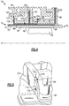
- FIG. 10 illustrates an example segment 72 with only the goalpost feather seal 98 of the feather seal assembly 74 shown.
- the first leg 102 and second leg 106 are a distance d 1 apart.
- the slot 90 and the slot 92 are a distance d 2 apart.
- the distance d 1 is different from the distance d 2 .
- the distance d 1 is less than the distance d 2 .
- the distance d 1 is 80-97 percent of the distance d 2 .
- the distance d 1 is 87-97 percent of the distance d 2 .
- the difference between distance d 1 and distance d 2 provides mistake-proofing for the seal assembly 70 .
- the legs 102 , 106 cannot be mistakenly assembled into the slots 90 and 92 .
- the goalpost feather seal 98 cannot be mistakenly assembled into the slot 88 and the slot 92 , or onto the slot 88 and the slot 90 .
- the goalpost feather seal 98 can therefore only be received in its proper position.
- the leg 106 also prevents the goalpost feather seal 98 from moving too far toward the axial end A 1 , such as during shipping of the assembly 70 , or at a disengagement of the gasket 113 (See FIG. 9 ), by eventually contacting the aft surface 89 of the first hook 82 .
- the goalpost feather seal 98 provides assembly mistake-proofing and added retention of the feather seal assembly 74 .
Abstract
Description
Claims (20)
Priority Applications (2)
| Application Number | Priority Date | Filing Date | Title |
|---|---|---|---|
| US15/927,145 US10633994B2 (en) | 2018-03-21 | 2018-03-21 | Feather seal assembly |
| EP19164118.2A EP3543469B8 (en) | 2018-03-21 | 2019-03-20 | Blade outer air seal assembly with feather seal |
Applications Claiming Priority (1)
| Application Number | Priority Date | Filing Date | Title |
|---|---|---|---|
| US15/927,145 US10633994B2 (en) | 2018-03-21 | 2018-03-21 | Feather seal assembly |
Publications (2)
| Publication Number | Publication Date |
|---|---|
| US20190292927A1 US20190292927A1 (en) | 2019-09-26 |
| US10633994B2 true US10633994B2 (en) | 2020-04-28 |
Family
ID=65894879
Family Applications (1)
| Application Number | Title | Priority Date | Filing Date |
|---|---|---|---|
| US15/927,145 Active 2038-07-04 US10633994B2 (en) | 2018-03-21 | 2018-03-21 | Feather seal assembly |
Country Status (2)
| Country | Link |
|---|---|
| US (1) | US10633994B2 (en) |
| EP (1) | EP3543469B8 (en) |
Cited By (1)
| Publication number | Priority date | Publication date | Assignee | Title |
|---|---|---|---|---|
| US20200248566A1 (en) * | 2019-02-05 | 2020-08-06 | United Technologies Corporation | Feather seals with leakage metering |
Families Citing this family (1)
| Publication number | Priority date | Publication date | Assignee | Title |
|---|---|---|---|---|
| US10633995B2 (en) * | 2018-07-31 | 2020-04-28 | United Technologies Corporation | Sealing surface for ceramic matrix composite blade outer air seal |
Citations (13)
| Publication number | Priority date | Publication date | Assignee | Title |
|---|---|---|---|---|
| US4477086A (en) * | 1982-11-01 | 1984-10-16 | United Technologies Corporation | Seal ring with slidable inner element bridging circumferential gap |
| US4749333A (en) | 1986-05-12 | 1988-06-07 | The United States Of America As Represented By The Secretary Of The Air Force | Vane platform sealing and retention means |
| WO1999030009A1 (en) | 1997-12-05 | 1999-06-17 | Pratt & Whitney Canada Corp. | Seal assembly for a gas turbine engine |
| US5988975A (en) | 1996-05-20 | 1999-11-23 | Pratt & Whitney Canada Inc. | Gas turbine engine shroud seals |
| US20050152777A1 (en) | 2004-01-08 | 2005-07-14 | Thompson Jeff B. | Resilent seal on leading edge of turbine inner shroud |
| US20050232752A1 (en) * | 2004-04-15 | 2005-10-20 | David Meisels | Turbine shroud cooling system |
| US20070025837A1 (en) | 2005-07-30 | 2007-02-01 | Pezzetti Michael C Jr | Stator assembly, module and method for forming a rotary machine |
| US20070104571A1 (en) * | 2005-11-10 | 2007-05-10 | General Electric Company | Methods and apparatus for assembling turbine engines |
| US20100187762A1 (en) * | 2009-01-28 | 2010-07-29 | Alstom Technology Ltd | Strip seal and method for designing a strip seal |
| US20120189424A1 (en) * | 2011-01-24 | 2012-07-26 | Propheter-Hinckley Tracy A | Mateface cooling feather seal assembly |
| US8641371B2 (en) * | 2009-03-27 | 2014-02-04 | Honda Motor Co., Ltd. | Turbine shroud |
| US20150377050A1 (en) | 2014-06-27 | 2015-12-31 | Rolls-Royce Corporation | Turbine shroud with sealed blade track |
| US20160312634A1 (en) * | 2015-04-22 | 2016-10-27 | United Technologies Corporation | Seal |
-
2018
- 2018-03-21 US US15/927,145 patent/US10633994B2/en active Active
-
2019
- 2019-03-20 EP EP19164118.2A patent/EP3543469B8/en active Active
Patent Citations (16)
| Publication number | Priority date | Publication date | Assignee | Title |
|---|---|---|---|---|
| US4477086A (en) * | 1982-11-01 | 1984-10-16 | United Technologies Corporation | Seal ring with slidable inner element bridging circumferential gap |
| US4749333A (en) | 1986-05-12 | 1988-06-07 | The United States Of America As Represented By The Secretary Of The Air Force | Vane platform sealing and retention means |
| US5988975A (en) | 1996-05-20 | 1999-11-23 | Pratt & Whitney Canada Inc. | Gas turbine engine shroud seals |
| WO1999030009A1 (en) | 1997-12-05 | 1999-06-17 | Pratt & Whitney Canada Corp. | Seal assembly for a gas turbine engine |
| US20050152777A1 (en) | 2004-01-08 | 2005-07-14 | Thompson Jeff B. | Resilent seal on leading edge of turbine inner shroud |
| US20050232752A1 (en) * | 2004-04-15 | 2005-10-20 | David Meisels | Turbine shroud cooling system |
| US7600967B2 (en) * | 2005-07-30 | 2009-10-13 | United Technologies Corporation | Stator assembly, module and method for forming a rotary machine |
| US20070025837A1 (en) | 2005-07-30 | 2007-02-01 | Pezzetti Michael C Jr | Stator assembly, module and method for forming a rotary machine |
| US20070104571A1 (en) * | 2005-11-10 | 2007-05-10 | General Electric Company | Methods and apparatus for assembling turbine engines |
| US20100187762A1 (en) * | 2009-01-28 | 2010-07-29 | Alstom Technology Ltd | Strip seal and method for designing a strip seal |
| EP2213841A1 (en) | 2009-01-28 | 2010-08-04 | Alstom Technology Ltd | Strip seal and method for designing a strip seal |
| US8534675B2 (en) | 2009-01-28 | 2013-09-17 | Alstom Technology Ltd | Strip seal and method for designing a strip seal |
| US8641371B2 (en) * | 2009-03-27 | 2014-02-04 | Honda Motor Co., Ltd. | Turbine shroud |
| US20120189424A1 (en) * | 2011-01-24 | 2012-07-26 | Propheter-Hinckley Tracy A | Mateface cooling feather seal assembly |
| US20150377050A1 (en) | 2014-06-27 | 2015-12-31 | Rolls-Royce Corporation | Turbine shroud with sealed blade track |
| US20160312634A1 (en) * | 2015-04-22 | 2016-10-27 | United Technologies Corporation | Seal |
Non-Patent Citations (1)
| Title |
|---|
| European Search Report for European Application No. 19164118.2, dated Jun. 4, 2019. |
Cited By (2)
| Publication number | Priority date | Publication date | Assignee | Title |
|---|---|---|---|---|
| US20200248566A1 (en) * | 2019-02-05 | 2020-08-06 | United Technologies Corporation | Feather seals with leakage metering |
| US11111794B2 (en) * | 2019-02-05 | 2021-09-07 | United Technologies Corporation | Feather seals with leakage metering |
Also Published As
| Publication number | Publication date |
|---|---|
| EP3543469A1 (en) | 2019-09-25 |
| US20190292927A1 (en) | 2019-09-26 |
| EP3543469B1 (en) | 2021-01-06 |
| EP3543469B8 (en) | 2021-04-07 |
Similar Documents
| Publication | Publication Date | Title |
|---|---|---|
| US10550706B2 (en) | Wrapped dog bone seal | |
| US10072517B2 (en) | Gas turbine engine component having variable width feather seal slot | |
| US11421558B2 (en) | Gas turbine engine component | |
| US10753220B2 (en) | Gas turbine engine component | |
| EP3112606B1 (en) | A seal for a gas turbine engine | |
| US9617866B2 (en) | Blade outer air seal for a gas turbine engine | |
| US10329937B2 (en) | Flowpath component for a gas turbine engine including a chordal seal | |
| US10954953B2 (en) | Rotor hub seal | |
| EP2985419B1 (en) | Turbomachine blade assembly with blade root seals | |
| EP3428408A1 (en) | Gas turbine engine variable vane end wall insert | |
| EP3068997B1 (en) | Segmented seal for gas turbine engine | |
| EP3543469B1 (en) | Blade outer air seal assembly with feather seal | |
| US20180080335A1 (en) | Gas turbine engine sealing arrangement | |
| US10415401B2 (en) | Airfoil retention assembly for a gas turbine engine | |
| US10890079B2 (en) | Gas turbine engine arc segments with arced walls | |
| US10648479B2 (en) | Stator segment circumferential gap seal | |
| US10047617B2 (en) | Gas turbine engine airfoil platform edge geometry | |
| US11111802B2 (en) | Seal for a gas turbine engine | |
| EP3495621A1 (en) | Support ring with fluid flow metering |
Legal Events
| Date | Code | Title | Description |
|---|---|---|---|
| AS | Assignment |
Owner name: UNITED TECHNOLOGIES CORPORATION, CONNECTICUT Free format text: ASSIGNMENT OF ASSIGNORS INTEREST;ASSIGNOR:BARKER, WILLIAM M.;REEL/FRAME:045298/0785 Effective date: 20180321 |
|
| FEPP | Fee payment procedure |
Free format text: ENTITY STATUS SET TO UNDISCOUNTED (ORIGINAL EVENT CODE: BIG.); ENTITY STATUS OF PATENT OWNER: LARGE ENTITY |
|
| AS | Assignment |
Owner name: UNITED STATES GOVERNMENT AS REPRESENTED BY THE SEC Free format text: CONFIRMATORY LICENSE;ASSIGNOR:UNITED TECHNOLOGIES CORPORATION PRATT & WHITNEY;REEL/FRAME:046137/0364 Effective date: 20180417 Owner name: UNITED STATES GOVERNMENT AS REPRESENTED BY THE SECRETARY OF THE ARMY, DISTRICT OF COLUMBIA Free format text: CONFIRMATORY LICENSE;ASSIGNOR:UNITED TECHNOLOGIES CORPORATION PRATT & WHITNEY;REEL/FRAME:046137/0364 Effective date: 20180417 |
|
| STPP | Information on status: patent application and granting procedure in general |
Free format text: NON FINAL ACTION MAILED |
|
| STPP | Information on status: patent application and granting procedure in general |
Free format text: RESPONSE TO NON-FINAL OFFICE ACTION ENTERED AND FORWARDED TO EXAMINER |
|
| STPP | Information on status: patent application and granting procedure in general |
Free format text: NOTICE OF ALLOWANCE MAILED -- APPLICATION RECEIVED IN OFFICE OF PUBLICATIONS |
|
| STPP | Information on status: patent application and granting procedure in general |
Free format text: AWAITING TC RESP., ISSUE FEE NOT PAID |
|
| STCF | Information on status: patent grant |
Free format text: PATENTED CASE |
|
| AS | Assignment |
Owner name: RAYTHEON TECHNOLOGIES CORPORATION, MASSACHUSETTS Free format text: CHANGE OF NAME;ASSIGNOR:UNITED TECHNOLOGIES CORPORATION;REEL/FRAME:054062/0001 Effective date: 20200403 |
|
| AS | Assignment |
Owner name: RAYTHEON TECHNOLOGIES CORPORATION, CONNECTICUT Free format text: CORRECTIVE ASSIGNMENT TO CORRECT THE AND REMOVE PATENT APPLICATION NUMBER 11886281 AND ADD PATENT APPLICATION NUMBER 14846874. TO CORRECT THE RECEIVING PARTY ADDRESS PREVIOUSLY RECORDED AT REEL: 054062 FRAME: 0001. ASSIGNOR(S) HEREBY CONFIRMS THE CHANGE OF ADDRESS;ASSIGNOR:UNITED TECHNOLOGIES CORPORATION;REEL/FRAME:055659/0001 Effective date: 20200403 |
|
| AS | Assignment |
Owner name: RTX CORPORATION, CONNECTICUT Free format text: CHANGE OF NAME;ASSIGNOR:RAYTHEON TECHNOLOGIES CORPORATION;REEL/FRAME:064714/0001 Effective date: 20230714 |
|
| MAFP | Maintenance fee payment |
Free format text: PAYMENT OF MAINTENANCE FEE, 4TH YEAR, LARGE ENTITY (ORIGINAL EVENT CODE: M1551); ENTITY STATUS OF PATENT OWNER: LARGE ENTITY Year of fee payment: 4 |