EP3693268B1 - Adaptive modellprädiktive steuerung für elektrischen hybridantrieb - Google Patents
Adaptive modellprädiktive steuerung für elektrischen hybridantrieb Download PDFInfo
- Publication number
- EP3693268B1 EP3693268B1 EP20155575.2A EP20155575A EP3693268B1 EP 3693268 B1 EP3693268 B1 EP 3693268B1 EP 20155575 A EP20155575 A EP 20155575A EP 3693268 B1 EP3693268 B1 EP 3693268B1
- Authority
- EP
- European Patent Office
- Prior art keywords
- model
- hybrid electric
- propulsion system
- composite
- reduced
- Prior art date
- Legal status (The legal status is an assumption and is not a legal conclusion. Google has not performed a legal analysis and makes no representation as to the accuracy of the status listed.)
- Active
Links
- 230000003044 adaptive effect Effects 0.000 title description 2
- 239000002131 composite material Substances 0.000 claims description 64
- 239000012636 effector Substances 0.000 claims description 37
- 238000005457 optimization Methods 0.000 claims description 33
- 238000000034 method Methods 0.000 claims description 29
- 238000005192 partition Methods 0.000 claims description 26
- 230000005540 biological transmission Effects 0.000 claims description 16
- 230000035945 sensitivity Effects 0.000 claims description 16
- 238000004146 energy storage Methods 0.000 claims description 11
- 238000001514 detection method Methods 0.000 claims description 8
- 239000000446 fuel Substances 0.000 description 12
- 230000006870 function Effects 0.000 description 12
- 238000010586 diagram Methods 0.000 description 5
- 230000008859 change Effects 0.000 description 4
- 230000003750 conditioning effect Effects 0.000 description 4
- 238000012545 processing Methods 0.000 description 4
- 230000008878 coupling Effects 0.000 description 3
- 238000010168 coupling process Methods 0.000 description 3
- 238000005859 coupling reaction Methods 0.000 description 3
- 230000009467 reduction Effects 0.000 description 3
- 230000003068 static effect Effects 0.000 description 3
- 230000008901 benefit Effects 0.000 description 2
- 239000003990 capacitor Substances 0.000 description 2
- 238000004891 communication Methods 0.000 description 2
- 238000012937 correction Methods 0.000 description 2
- 230000004044 response Effects 0.000 description 2
- 230000001052 transient effect Effects 0.000 description 2
- 230000001133 acceleration Effects 0.000 description 1
- 230000009286 beneficial effect Effects 0.000 description 1
- 230000006835 compression Effects 0.000 description 1
- 238000007906 compression Methods 0.000 description 1
- 238000013461 design Methods 0.000 description 1
- 230000000694 effects Effects 0.000 description 1
- 238000000605 extraction Methods 0.000 description 1
- 238000009396 hybridization Methods 0.000 description 1
- 230000006872 improvement Effects 0.000 description 1
- 230000010354 integration Effects 0.000 description 1
- 239000011159 matrix material Substances 0.000 description 1
- 238000005259 measurement Methods 0.000 description 1
- 230000007246 mechanism Effects 0.000 description 1
- 230000003287 optical effect Effects 0.000 description 1
- 238000010248 power generation Methods 0.000 description 1
- 230000008569 process Effects 0.000 description 1
- 238000000926 separation method Methods 0.000 description 1
- 238000000638 solvent extraction Methods 0.000 description 1
- 239000013589 supplement Substances 0.000 description 1
- 230000007704 transition Effects 0.000 description 1
Images


Classifications
-
- F—MECHANICAL ENGINEERING; LIGHTING; HEATING; WEAPONS; BLASTING
- F01—MACHINES OR ENGINES IN GENERAL; ENGINE PLANTS IN GENERAL; STEAM ENGINES
- F01D—NON-POSITIVE DISPLACEMENT MACHINES OR ENGINES, e.g. STEAM TURBINES
- F01D15/00—Adaptations of machines or engines for special use; Combinations of engines with devices driven thereby
- F01D15/10—Adaptations for driving, or combinations with, electric generators
-
- F—MECHANICAL ENGINEERING; LIGHTING; HEATING; WEAPONS; BLASTING
- F02—COMBUSTION ENGINES; HOT-GAS OR COMBUSTION-PRODUCT ENGINE PLANTS
- F02C—GAS-TURBINE PLANTS; AIR INTAKES FOR JET-PROPULSION PLANTS; CONTROLLING FUEL SUPPLY IN AIR-BREATHING JET-PROPULSION PLANTS
- F02C9/00—Controlling gas-turbine plants; Controlling fuel supply in air- breathing jet-propulsion plants
-
- B—PERFORMING OPERATIONS; TRANSPORTING
- B64—AIRCRAFT; AVIATION; COSMONAUTICS
- B64D—EQUIPMENT FOR FITTING IN OR TO AIRCRAFT; FLIGHT SUITS; PARACHUTES; ARRANGEMENTS OR MOUNTING OF POWER PLANTS OR PROPULSION TRANSMISSIONS IN AIRCRAFT
- B64D27/00—Arrangement or mounting of power plant in aircraft; Aircraft characterised thereby
- B64D27/02—Aircraft characterised by the type or position of power plant
-
- B64D27/026—
-
- F—MECHANICAL ENGINEERING; LIGHTING; HEATING; WEAPONS; BLASTING
- F05—INDEXING SCHEMES RELATING TO ENGINES OR PUMPS IN VARIOUS SUBCLASSES OF CLASSES F01-F04
- F05D—INDEXING SCHEME FOR ASPECTS RELATING TO NON-POSITIVE-DISPLACEMENT MACHINES OR ENGINES, GAS-TURBINES OR JET-PROPULSION PLANTS
- F05D2220/00—Application
- F05D2220/30—Application in turbines
- F05D2220/32—Application in turbines in gas turbines
- F05D2220/323—Application in turbines in gas turbines for aircraft propulsion, e.g. jet engines
-
- F—MECHANICAL ENGINEERING; LIGHTING; HEATING; WEAPONS; BLASTING
- F05—INDEXING SCHEMES RELATING TO ENGINES OR PUMPS IN VARIOUS SUBCLASSES OF CLASSES F01-F04
- F05D—INDEXING SCHEME FOR ASPECTS RELATING TO NON-POSITIVE-DISPLACEMENT MACHINES OR ENGINES, GAS-TURBINES OR JET-PROPULSION PLANTS
- F05D2220/00—Application
- F05D2220/70—Application in combination with
- F05D2220/76—Application in combination with an electrical generator
-
- F—MECHANICAL ENGINEERING; LIGHTING; HEATING; WEAPONS; BLASTING
- F05—INDEXING SCHEMES RELATING TO ENGINES OR PUMPS IN VARIOUS SUBCLASSES OF CLASSES F01-F04
- F05D—INDEXING SCHEME FOR ASPECTS RELATING TO NON-POSITIVE-DISPLACEMENT MACHINES OR ENGINES, GAS-TURBINES OR JET-PROPULSION PLANTS
- F05D2240/00—Components
- F05D2240/60—Shafts
-
- F—MECHANICAL ENGINEERING; LIGHTING; HEATING; WEAPONS; BLASTING
- F05—INDEXING SCHEMES RELATING TO ENGINES OR PUMPS IN VARIOUS SUBCLASSES OF CLASSES F01-F04
- F05D—INDEXING SCHEME FOR ASPECTS RELATING TO NON-POSITIVE-DISPLACEMENT MACHINES OR ENGINES, GAS-TURBINES OR JET-PROPULSION PLANTS
- F05D2260/00—Function
- F05D2260/80—Diagnostics
-
- F—MECHANICAL ENGINEERING; LIGHTING; HEATING; WEAPONS; BLASTING
- F05—INDEXING SCHEMES RELATING TO ENGINES OR PUMPS IN VARIOUS SUBCLASSES OF CLASSES F01-F04
- F05D—INDEXING SCHEME FOR ASPECTS RELATING TO NON-POSITIVE-DISPLACEMENT MACHINES OR ENGINES, GAS-TURBINES OR JET-PROPULSION PLANTS
- F05D2270/00—Control
- F05D2270/01—Purpose of the control system
- F05D2270/09—Purpose of the control system to cope with emergencies
-
- F—MECHANICAL ENGINEERING; LIGHTING; HEATING; WEAPONS; BLASTING
- F05—INDEXING SCHEMES RELATING TO ENGINES OR PUMPS IN VARIOUS SUBCLASSES OF CLASSES F01-F04
- F05D—INDEXING SCHEME FOR ASPECTS RELATING TO NON-POSITIVE-DISPLACEMENT MACHINES OR ENGINES, GAS-TURBINES OR JET-PROPULSION PLANTS
- F05D2270/00—Control
- F05D2270/01—Purpose of the control system
- F05D2270/20—Purpose of the control system to optimize the performance of a machine
-
- F—MECHANICAL ENGINEERING; LIGHTING; HEATING; WEAPONS; BLASTING
- F05—INDEXING SCHEMES RELATING TO ENGINES OR PUMPS IN VARIOUS SUBCLASSES OF CLASSES F01-F04
- F05D—INDEXING SCHEME FOR ASPECTS RELATING TO NON-POSITIVE-DISPLACEMENT MACHINES OR ENGINES, GAS-TURBINES OR JET-PROPULSION PLANTS
- F05D2270/00—Control
- F05D2270/40—Type of control system
- F05D2270/44—Type of control system active, predictive, or anticipative
-
- F—MECHANICAL ENGINEERING; LIGHTING; HEATING; WEAPONS; BLASTING
- F05—INDEXING SCHEMES RELATING TO ENGINES OR PUMPS IN VARIOUS SUBCLASSES OF CLASSES F01-F04
- F05D—INDEXING SCHEME FOR ASPECTS RELATING TO NON-POSITIVE-DISPLACEMENT MACHINES OR ENGINES, GAS-TURBINES OR JET-PROPULSION PLANTS
- F05D2270/00—Control
- F05D2270/80—Devices generating input signals, e.g. transducers, sensors, cameras or strain gauges
-
- Y—GENERAL TAGGING OF NEW TECHNOLOGICAL DEVELOPMENTS; GENERAL TAGGING OF CROSS-SECTIONAL TECHNOLOGIES SPANNING OVER SEVERAL SECTIONS OF THE IPC; TECHNICAL SUBJECTS COVERED BY FORMER USPC CROSS-REFERENCE ART COLLECTIONS [XRACs] AND DIGESTS
- Y02—TECHNOLOGIES OR APPLICATIONS FOR MITIGATION OR ADAPTATION AGAINST CLIMATE CHANGE
- Y02T—CLIMATE CHANGE MITIGATION TECHNOLOGIES RELATED TO TRANSPORTATION
- Y02T50/00—Aeronautics or air transport
- Y02T50/60—Efficient propulsion technologies, e.g. for aircraft
Definitions
- the subject matter disclosed herein generally relates to rotating machinery and, more particularly, to a method and an apparatus for model predictive control for hybrid electric propulsion.
- a hybrid electric propulsion system for an aircraft can include a gas turbine engine and at least one electric motor that supplements performance of the gas turbine engine.
- Gas turbine engines and electric motors typically have separate control laws to manage gas turbine power and electric power. Separate control laws can increase challenges in effectively managing events, such as rapid transients, thermal-mechanical stress, component lifespan, and/or other control goals.
- WO 2014/158240 discloses a hybrid turbo electric aero-propulsion system control method and apparatus.
- US 2004/102890 discloses a method and apparatus for model predictive control of aircraft gas turbine engines.
- a hybrid electric propulsion system includes a gas turbine engine having at least one compressor section and at least one turbine section operably coupled to a shaft.
- the hybrid electric propulsion system includes an electrical power system comprising an electric motor configured to augment rotational power of the shaft of the gas turbine engine, a mechanical power transmission comprising a gearbox operably coupled between the shaft and the electrical power system; and a plurality of hybrid electric system control effectors operable to control a plurality of states of one or more the gas turbine engine and the electrical power system.
- a controller is operable to determine an estimate of hybrid electric propulsion system parameters based on a composite system model and sensor data, determine a model predictive control state and a prediction based on the hybrid electric propulsion system parameters and the composite system model, determine a model predictive control optimization for the plurality of hybrid electric system control effectors based on the model predictive control state and the prediction using a plurality of reduced-order partitions of the composite system model, and actuate the hybrid electric system control effectors based on the model predictive control optimization.
- the system may include where the controller is further configured to update a plurality of composite system model states of the composite system model based on detection of one or more faults.
- the system may include where the controller is further configured to update one or more reduced-order values based on the reduced-order partitions of the composite system model states of the composite system model.
- the system may include where the one or more reduced-order values are reduced-order Jacobian values based on a plurality of Jacobian equations associated with the composite system model.
- the system may include where the reduced-order partitions include partitions of a propulsion system model including a gas turbine engine model, a mechanical power transmission model, and an electrical power system model that preserve a plurality of dominant states for each partition.
- a propulsion system model including a gas turbine engine model, a mechanical power transmission model, and an electrical power system model that preserve a plurality of dominant states for each partition.
- the system may include where the composite system model includes the propulsion system model, an optimization objective function, and a plurality of constraints.
- the system may include where the Jacobian equations associated with the composite system model include a plurality of model sensitivity matrices that are updated based on the detection of one or more faults.
- the system may include where the model predictive control optimization uses the model sensitivity matrices to determine a set of changes to the hybrid electric system control effectors that optimizes the optimization objective function over a finite time horizon while maintaining the constraints.
- the system may include an electric generator configured to extract power from the shaft, wherein the composite system model includes a plurality of electrical and mechanical physics-based models of at least the gas turbine engine, the electric motor, the electric generator, and one or more mechanical power transmissions.
- the system may include where the means for controlling the hybrid electric system control effectors includes a controller operable to determine an estimate of a plurality of hybrid electric propulsion system parameters based on a composite system model and a plurality of sensor data, determine a model predictive control state and a prediction based on the hybrid electric propulsion system parameters and the composite system model, determine a model predictive control optimization for the hybrid electric system control effectors based on the model predictive control state and the prediction using a plurality of reduced-order partitions of the composite system model, and actuate the hybrid electric system control effectors based on the model predictive control optimization.
- the means for controlling the hybrid electric system control effectors includes a controller operable to determine an estimate of a plurality of hybrid electric propulsion system parameters based on a composite system model and a plurality of sensor data, determine a model predictive control state and a prediction based on the hybrid electric propulsion system parameters and the composite system model, determine a model predictive control optimization for the hybrid electric system control effectors based on the model predictive control state and the
- a method for controlling a hybrid electric propulsion system includes determining, by a controller, an estimate of a plurality of hybrid electric propulsion system parameters based on a composite system model and a plurality of sensor data, determining, by the controller, a model predictive control state and a prediction based on the hybrid electric propulsion system parameters and the composite system model, determining, by the controller, a model predictive control optimization for a plurality of hybrid electric system control effectors based on the model predictive control state and the prediction using a plurality of reduced-order partitions of the composite system model, and actuating, by the controller, the hybrid electric system control effectors based on the model predictive control optimization
- the hybrid electric propulsion system comprises a gas turbine engine comprising at least one compressor section and at least one turbine section operably coupled to a shaft, an electrical power system comprising an electric motor configured to augment rotational power of the shaft, and a mechanical power transmission comprising a gearbox operably coupled between the shaft and the electrical power system.
- a technical effect of the apparatus, systems and methods is achieved by performing model predictive control for a hybrid electric propulsion system.
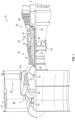
- FIG. 1 schematically illustrates a gas turbine engine 20.
- the gas turbine engine 20 is disclosed herein as a two-spool turbofan that generally incorporates a fan section 22, a compressor section 24, a combustor section 26 and a turbine section 28.
- the fan section 22 drives air along a bypass flow path B in a bypass duct, while the compressor section 24 drives air along a core flow path C for compression and communication into the combustor section 26 then expansion through the turbine section 28.
- FIG. 1 schematically illustrates a gas turbine engine 20.
- the gas turbine engine 20 is disclosed herein as a two-spool turbofan that generally incorporates a fan section 22, a compressor section 24, a combustor section 26 and a turbine section 28.
- the fan section 22 drives air along a bypass flow path B in a bypass duct
- the compressor section 24 drives air along a core flow path C for compression and communication into the combustor section 26 then expansion through the turbine section 28.
- the exemplary engine 20 generally includes a low speed spool 30 and a high speed spool 32 mounted for rotation about an engine central longitudinal axis A relative to an engine static structure 36 via several bearing systems 38. It should be understood that various bearing systems 38 at various locations may alternatively or additionally be provided, and the location of bearing systems 38 may be varied as appropriate to the application.
- the low speed spool 30 generally includes an inner shaft 40 that interconnects a fan 42, a low pressure compressor 44 and a low pressure turbine 46.
- the inner shaft 40 is connected to the fan 42 through a speed change mechanism, which in exemplary gas turbine engine 20 is illustrated as a geared architecture 48 to drive the fan 42 at a lower speed than the low speed spool 30.
- the high speed spool 32 includes an outer shaft 50 that interconnects a high pressure compressor 52 and high pressure turbine 54.
- a combustor 56 is arranged in exemplary gas turbine 20 between the high pressure compressor 52 and the high pressure turbine 54.
- An engine static structure 36 is arranged generally between the high pressure turbine 54 and the low pressure turbine 46.
- the engine static structure 36 further supports bearing systems 38 in the turbine section 28.
- the inner shaft 40 and the outer shaft 50 are concentric and rotate via bearing systems 38 about the engine central longitudinal axis A which is collinear with their longitudinal axes.
- each of the positions of the fan section 22, compressor section 24, combustor section 26, turbine section 28, and fan drive gear system 48 may be varied.
- gear system 48 may be located aft of combustor section 26 or even aft of turbine section 28, and fan section 22 may be positioned forward or aft of the location of gear system 48.
- the engine 20 in one example is a high-bypass geared aircraft engine.
- the engine 20 bypass ratio is greater than about six (6), with an example embodiment being greater than about ten (10)
- the geared architecture 48 is an epicyclic gear train, such as a planetary gear system or other gear system, with a gear reduction ratio of greater than about 2.3
- the low pressure turbine 46 has a pressure ratio that is greater than about five.
- the engine 20 bypass ratio is greater than about ten (10:1)
- the fan diameter is significantly larger than that of the low pressure compressor 44
- the low pressure turbine 46 has a pressure ratio that is greater than about five 5:1.
- Low pressure turbine 46 pressure ratio is pressure measured prior to inlet of low pressure turbine 46 as related to the pressure at the outlet of the low pressure turbine 46 prior to an exhaust nozzle.
- the geared architecture 48 may be an epicycle gear train, such as a planetary gear system or other gear system, with a gear reduction ratio of greater than about 2.3:1. It should be understood, however, that the above parameters are only exemplary of one embodiment of a geared architecture engine and that the present disclosure is applicable to other gas turbine engines including direct drive turbofans.
- the fan section 22 of the engine 20 is designed for a particular flight condition--typically cruise at about 0.8Mach and about 35,000 feet (10,668 meters).
- 'TSFC' Thrust Specific Fuel Consumption
- Low fan pressure ratio is the pressure ratio across the fan blade alone, without a Fan Exit Guide Vane (“FEGV”) system.
- the low fan pressure ratio as disclosed herein according to one non-limiting embodiment is less than about 1.45.
- Low corrected fan tip speed is the actual fan tip speed in ft/sec divided by an industry standard temperature correction of [(Tram °R)/(518.7 °R)] ⁇ 0.5.
- the "Low corrected fan tip speed” as disclosed herein according to one non-limiting embodiment is less than about 1150 ft/second (350.5 m/sec).
- FIG. 1 illustrates one example of the gas turbine engine 20
- any number of spools, inclusion or omission of the gear system 48, and/or other elements and subsystems are contemplated.
- rotor systems described herein can be used in a variety of applications and need not be limited to gas turbine engines for aircraft applications.
- rotor systems can be included in power generation systems, which may be ground-based as a fixed position or mobile system, and other such applications.
- FIG. 2 illustrates a hybrid electric propulsion system 100 (also referred to as hybrid gas turbine engine 100) including a gas turbine engine 120 operably coupled to an electrical power system 210 as part of a hybrid electric aircraft.
- One or more mechanical power transmissions 150 can be operably coupled between the gas turbine engine 120 and the electrical power system 210.
- the gas turbine engine 120 can be an embodiment of the gas turbine engine 20 of FIG.
- the electrical power system 210 can include a first electric motor 212A configured to augment rotational power of the low speed spool 30 and a second electric motor 212B configured to augment rotational power of the high speed spool 32. Although two electric motors 212A, 212B are depicted in FIG.
- the electrical power system 210 can also include a first electric generator 213A configured to convert rotational power of the low speed spool 30 to electric power and a second electric generator 213B configured to convert rotational power of the high speed spool 32 to electric power.
- the electric motors 212A, 212B can be configured as a motor or a generator depending upon an operational mode or system configuration, and thus the electric generators 213A, 213B may be omitted.
- the mechanical power transmission 150A includes a gearbox operably coupled between the inner shaft 40 and a combination of the first electric motor 212A and first electric generator 213A.
- the mechanical power transmission 150B can include a gearbox operably coupled between the outer shaft 50 and a combination of the second electric motor 212B and second electric generator 213B.
- the mechanical power transmission 150A, 150B can be a clutch or other interfacing element(s).
- the electrical power system 210 can also include motor drive electronics 214A, 214B operable to condition current to the electric motors 212A, 212B (e.g., DC-to-AC converters).
- the electrical power system 210 can also include rectifier electronics 215A, 215B operable to condition current from the electric generators 213A, 213B (e.g., AC-to-DC converters).
- the motor drive electronics 214A, 214B and rectifier electronics 215A, 215B can interface with an energy storage management system 216 that further interfaces with an energy storage system 218.
- the energy storage management system 216 can be a bi-directional DC-DC converter that regulates voltages between energy storage system 218 and electronics 214A, 214B, 215A, 215B.
- the energy storage system 218 can include one or more energy storage devices, such as a battery, a super capacitor, an ultra capacitor, and the like.
- a power conditioning unit 220 and/or other components can be powered by the energy storage system 218.
- the power conditioning unit 220 can distribute electric power to support actuation and other functions of the gas turbine engine 120.
- the power conditioning unit 220 can power an integrated fuel control unit 222 to control fuel flow to the gas turbine engine 120.
- the power conditioning unit 220 can power a plurality of actuators 224, such as one or more of a low pressure compressor bleed valve actuator 226, a low pressure compressor vane actuator 228, a high pressure compressor vane actuator 230, an active clearance control actuator 232, and other such effectors.
- any effectors that can change a state of the gas turbine engine 120 and/or the electrical power system 210 maybe referred to as hybrid electric system control effectors 240.
- Examples of the hybrid electric system control effectors 240 can include the electric motors 212A, 212B, electric generators 213A, 213B, integrated fuel control unit 222, actuators 224 and/or other elements (not depicted).
- FIG. 3 is a schematic diagram of control signal paths 250 of the hybrid electric propulsion system 100 of FIG. 2 and is described with continued reference to FIGS. 1 and 2 .
- a controller 256 can interface with the motor drive electronics 214A, 214B, rectifier electronics 215A, 215B, energy storage management system 216, integrated fuel control unit 222, actuators 224, and/or other components (not depicted) of the hybrid electric propulsion system 100.
- the controller 256 can control and monitor for fault conditions of the gas turbine engine 120 and/or the electrical power system 210.
- the controller 256 can be integrally formed or otherwise in communication with a full authority digital engine control (FADEC) of the gas turbine engine 120.
- FADEC full authority digital engine control
- the controller 256 can include a processing system 260, a memory system 262, and an input/output interface 264.
- the controller 256 can also include various operational controls, such as a model predictive control 266 that controls the hybrid electric system control effectors 240 as further described herein.
- the processing system 260 can include any type or combination of central processing unit (CPU), including one or more of: a microprocessor, a digital signal processor (DSP), a microcontroller, an application specific integrated circuit (ASIC), a field programmable gate array (FPGA), or the like.
- the memory system 262 can store data and instructions that are executed by the processing system 260.
- the memory system 262 may include random access memory (RAM), read only memory (ROM), or other electronic, optical, magnetic, or any other computer readable medium onto which is stored data and algorithms in a non-transitory form.
- the input/output interface 264 is configured to collect sensor data from the one or more system sensors ( FIG.
- the controller 256 provides a means for controlling the hybrid electric system control effectors 240 based on a model predictive control 266 that is dynamically updated during operation of the hybrid electric propulsion system 100.
- the means for controlling the hybrid electric system control effectors 240 can be otherwise subdivided, distributed, or combined with other control elements.
- the control system 300 includes the model predictive control 266 that may be embodied within the controller 256 of FIG. 3 and configured to interface with the hybrid electric propulsion system 100.
- the model predictive control 266 includes a composite system model 302 and computational modules to perform a state estimation 304, state and output prediction 306, determine reduced-order values (e.g., reduced-order Jacobian equations) 308, and constrained optimization 310.
- the composite system model 302 can include a propulsion system model 312, an optimization objective function 314, a plurality of constraints 316, and Jacobian equations 318 associated with the composite system model 302.
- the propulsion system model 312 can include a gas turbine engine model 320 of the gas turbine engine 120, a mechanical power transmission model 322 of the mechanical power transmission 150, and an electrical power system model 324 of the electrical power system 210.
- the composite system model 302 can provide model states 326, as well as modeled sensor values 327, to state estimation 304 which also receives sensor data from sensors 330 of the hybrid electric propulsion system 100.
- the state estimation 304 can produce updated state estimates 328, which are provided to update the composite system model 302.
- the state estimation block 304 also receives Jacobian values from composite system model 302. These Jacobian values are sensitivities of modeled sensor values 327 to changes in model states 326 and inputs.
- the Jacobian values are used by the state estimation algorithm within block 304 to compute updated state estimates that align modeled sensor values 327 with the actual sensor data 330. More specifically, in some embodiments, the state estimation algorithm within block 304 is an instance of moving horizon constrained estimation.
- the hybrid electric propulsion system 100 can have multiple potential solutions to achieving a given propulsion system thrust goal. This provides opportunities for real-time optimization of transient and steady-state system performance.
- the optimization objective function 314 can be configured to use electric power only during rapid accelerations, preserving engine life by lowering peak thermal-mechanical stresses that would otherwise be larger during rapid, fuel-only transients.
- a control law for this example can smoothly transition from transient electric power-assist to continuous, quasisteady gas turbine engine supplied power, while maintaining all engine and electric system variables within safe limits as defined in the constraints 316.
- the hybrid electric propulsion system 100 can be significantly more complex than a non-hybrid system, and subject to a larger number of failure modes.
- the performance advantages realized through hybridization can be accompanied by improvements in control system adaptability and tolerance to failures, such as detected and isolated propulsion system failures 332.
- the control system embodied in the model predictive control 266 can make a combination of continuous and discrete decisions through predictions over a plurality of future time steps, for instance, to modulate effectors (e.g., fuel, DC motor power) and/or make discrete decisions, such as power provision versus power extraction.
- the propulsion system model 312 can be used to predict future responses of the system states and outputs by the state and output prediction 306, which can be based on current values of the hybrid electric system control effectors 240.
- the constrained optimization 310 can use model sensitivity matrices (e.g., Jacobian equations 318 reduced as reduced-order values 308) to determine a set of changes to the hybrid electric system control effectors 240 as optimal effector commands 334 that optimize objective function 314, over a finite time horizon, while maintaining the hybrid electric propulsion system 100 within safe limits (e.g., constraints 316).
- the objectives and constraints may also be functions of current and future system inputs, states, and outputs, thus requiring objective and constraint sensitivities, in addition to model sensitivity matrices, to accurately predict/correct system trajectories and satisfy constraints.
- a battery state of charge objective can be a function of the difference of predicted propulsion system thrust and thrust required/requested by an airframe.
- a compressor pressure ratio constraint may be a function of predicted future compressor air flow rate.
- the sensitivity matrices of the Jacobian equations 318 and further reduced as reduced-order values 308 can be computed during operation of the hybrid electric propulsion system 100 rather than a priori in order to maximize adaptability of model predictive control 266 to failures 332.
- Propulsion system goals and airframe commands 336 can be updated during operation to change the optimization objective function 314 in order to adapt the model predictive control 266 to changing mission objectives.
- computational cost of the model predictive control 266 can be reduced by lowering the computational the cost of iteratively computing inverses of the model sensitivity matrices. Therefore, there can be a technical benefit to reducing the size of the sensitivity matrices through state order reduction.
- Some hybrid electric propulsion architectures such as a parallel architecture, have strong but sparse coupling between the aero-thermodynamic propulsion subsystem and the electric power subsystem, through, for example, a gearbox connecting an electric motor to a turbo-machinery shaft.
- the remaining and dominant dynamic states of the electrical subsystem may be largely independent of the dominant dynamic states of the gas turbine engine subsystem.
- This structure of a dynamic model can be characterized as a sparse and nearly block-diagonal structure that can help inform selection of dynamic states for reduced order Jacobians and potentially can leverage efficient sparse matrix algorithms.
- the propulsion system model 312 represents a multi-physics model including aero-thermodynamic, mechanical, and electrical dynamics. State partitioning of the propulsion system model 312 can preserve a quasi-block diagonal structure. A reduced order set of dominant dynamic states for each partition can be determined that preserves state physical identity. The selected reduced order states are used to compute reduced order Jacobians 308 from analytic Jacobian equations of the composite system model 318. The reduced-order Jacobian values 308 are then provided to the constrained optimization 310, which computes optimal effector commands given a set of propulsion system goal and airframe commands 336, objectives 314 and constraints 316, and current estimated state of the engine 328.
- FIG. 5 is a flow chart illustrating a method 400 for off-board modeling and analysis, in accordance with an embodiment.
- the method 400 may be performed, for example, by a computer system external to the hybrid electric propulsion system 100 to construct a composite propulsion system model 302, generate analytic Jacobian equations 318 for the composite system model, and select a set of reduced order model states for reduced order Jacobians 308 for the model predictive control 266 of FIG. 4 .
- the method 400 is described primarily with respect to the hybrid electric propulsion system 100 of FIG. 2 ; however, it will be understood that the method 400 can be performed with respect to other configurations (not depicted).
- a physics-based hybrid electric propulsion system model is constructed that corresponds to design characteristics of the hybrid electric propulsion system 100, as an initial configuration of the propulsion system model 312.
- propulsion system constraint exceedance equations can be determined based on propulsion system constraint equations 406 to determine values for the constraints 316.
- analytic Jacobian equations are generated for the composite system model 302 and implemented as software in the target controller 256 as the Jacobian equations 318, which can include first-order partial derivatives for a collection of dynamic states, adjustments, goals, limits, and the like.
- the analytical Jacobian equations for the composite system model 302 can be loaded as the Jacobian equations 318 into the controller 256.
- the physics-based hybrid electric propulsion system model of block 402 can be partitioned in dynamic states based on a coupling analysis.
- a reduced set of physics states can be selected for each partition based on singular value analysis and time scale separation.
- the reduced set of physics states for each partition can be provided as a set of state indices to load in the controller 256 for producing the reduced-order values 308.
- FIG. 6 is a flow chart illustrating a method 500 for controlling of a hybrid electric propulsion system, in accordance with an embodiment.
- the method 500 may be performed, for example, by the hybrid electric propulsion system 100 of FIG. 2 .
- the method 500 is described primarily with respect to the hybrid electric propulsion system 100 of FIG. 2 ; however, it will be understood that the method 500 can be performed on other configurations (not depicted).
- Method 500 pertains to the controller 256 executing embedded code for the model predictive control 266 to compute optimal hybrid propulsion system control effectors 518 and actuate these effectors 520.
- the composite system model 302, represented in part by differential equations 402, 404, and the corresponding Jacobians 318, are adaptive to detected failure states 332.
- a detected open circuit failure of motor drives 214A or 214B triggers a structural and/or parametric change to the composite system model 302 and corresponding Jacobians 318, reflecting physics of the failure state.
- Model state values from block 506 are used to calculate reduced order Jacobian values in block 508.
- Block 512 receives the model states from block 506 and computes updated state estimates 328, based on modeled sensor values 327 and propulsion system sensor data 330.
- the controller 256 can calculate the reduced-order values 308 (e.g., reduced-order Jacobian values) based on reduced order partitions defined by a reduced order set of physics states.
- controller 256 Indices for the reduced order set of physics states are set in controller 256 at initialization, as defined in block 416 of FIG. 5 and block 510 of FIG. 6 .
- the controller 256 can determine an estimate of hybrid electric propulsion system states based on sensor data from sensors 330 and modeled sensor values 327 and model states 326 of the composite system model 302.
- Initialization 514 of the composite system model 302 can be performed on the first pass of the model predictive control 266
- the controller 256 can execute the model predictive control 266 to determine the state and output prediction 306.
- the controller 256 can execute the model predictive control 266 to determine the constrained optimization 310 for optimal effector commands 334 of the hybrid electric system control effectors 240 based on the reduced-order Jacobian values 308 of block 508.
- the hybrid electric system control effectors 240 can be actuated based on the optimal effector commands 334.
- the method 500 can loop back to block 504 to continue with real-time control and updates as the hybrid electric propulsion system 100 operates.
- FIG. 7 is a flow chart illustrating a method 600 for control of a hybrid electric propulsion system, in accordance with an embodiment.
- the method 600 may be performed, for example, by the hybrid electric propulsion system 100 of FIG. 2 .
- the method 600 is described primarily with respect to the hybrid electric propulsion system 100 of FIG. 2 ; however, it will be understood that the method 600 can be performed on other configurations (not depicted).
- controller 256 can determine an estimate of a plurality of hybrid electric propulsion system parameters based on a composite system model 302 and a plurality of sensor data from sensors 330 using the state estimation 304.
- the controller 256 can determine a model predictive control state and a prediction using the state and output prediction 306 based on the hybrid electric propulsion system parameters and the composite system model 302.
- the controller 256 can determine a model predictive control optimization for a plurality of hybrid electric system control effectors 240 by the constrained optimization 310 based on the model predictive control state and the prediction using a plurality of reduced-order partitions of the composite system model 302.
- the controller 256 can actuate the hybrid electric system control effectors 240 based on the model predictive control optimization.
- the controller 256 can be configured to update a plurality of composite system model states of the composite system model 302 based on detection of one or more faults, such as detected and isolated propulsion system failures 332.
- the controller 256 can be further configured to update one or more reduced-order values 308 based on the reduced-order partitions of the composite system model states of the composite system model 302.
- the one or more reduced-order values 308 can be reduced-order Jacobian values based on a plurality of Jacobian equations 318 associated with the composite system model 302.
- the reduced-order partitions can include partitions of a propulsion system model 312 including a gas turbine engine model 320, a mechanical power transmission model 322, and an electrical power system model 324 that preserve a plurality of dominant states for each partition.
- the composite system model 302 can include the propulsion system model 312, an optimization objective function 314, and a plurality of constraints 316.
- the Jacobian equations 318 associated with the composite system model 302 can include a plurality of model sensitivity matrices that are updated based on the detection of one or more faults.
- the model predictive control optimization can use the model sensitivity matrices to determine a set of changes to the hybrid electric system control effectors 240 that optimizes the optimization objective function 314 over a finite time horizon while maintaining the constraints 316.
Landscapes
- Engineering & Computer Science (AREA)
- Chemical & Material Sciences (AREA)
- Combustion & Propulsion (AREA)
- Mechanical Engineering (AREA)
- General Engineering & Computer Science (AREA)
- Aviation & Aerospace Engineering (AREA)
- Feedback Control In General (AREA)
Claims (14)
- Elektrisches Hybridantriebssystem (100), umfassend:ein Gasturbinentriebwerk (20), das mindestens ein Verdichterteilstück (24) und mindestens ein Turbinenteilstück (28), das an eine Welle wirkgekoppelt ist, umfasst;ein elektrisches Versorgungssystem (210), das einen Elektromotor (212A, 212B) umfasst, der dazu konfiguriert ist, eine Drehleistung der Welle des Gasturbinentriebwerks zu erhöhen;eine mechanische Kraftübertragung (150A, 150B), die ein Getriebe umfasst, das zwischen der Welle und dem elektrischen Versorgungssystem wirkgekoppelt ist; undeine Vielzahl von Steuerungseffektoren (240) des elektrischen Hybridsystems, die betreibbar ist, um eine Vielzahl von Zuständen eines oder mehrerer von dem Gasturbinentriebwerk unddem elektrischen Versorgungssystem zu steuern; undeine Steuerung (256), die zu Folgendem betreibbar ist:Bestimmen einer Schätzung einer Vielzahl von Parametern des elektrischen Hybridantriebssystems basierend auf einem Verbundsystemmodell (302) und einer Vielzahl von Sensordaten;Bestimmen eines Zustands einer modellprädiktiven Steuerung und einer Vorhersage basierend auf den Parametern des elektrischen Hybridantriebssystems und dem Verbundsystemmodell;Bestimmen einer Optimierung der modellprädiktiven Steuerung für die Vielzahl von Steuerungseffektoren (240) des elektrischen Hybridsystems basierend auf dem Zustand der modellprädiktiven Steuerung und der Vorhersage unter Verwendung einer Vielzahl von Partitionen reduzierter Ordnung des Verbundsystemmodells; undBetätigen der Steuerungseffektoren des elektrischen Hybridsystems basierend auf der Optimierung der modellprädiktiven Steuerung.
- Elektrisches Hybridantriebssystem nach Anspruch 1, wobei die Steuerung (256) ferner dazu konfiguriert ist, eine Vielzahl von Verbundsystemmodellzuständen des Verbundsystemmodells (302) basierend auf der Detektion eines oder mehrerer Fehler zu aktualisieren.
- Elektrisches Hybridantriebssystem nach Anspruch 2, wobei die Steuerung (256) ferner dazu konfiguriert ist, einen oder mehrere Werte reduzierter Ordnung basierend auf den Partitionen reduzierter Ordnung der Verbundsystemmodellzustände des Verbundsystemmodells zu aktualisieren.
- Elektrisches Hybridantriebssystem nach Anspruch 3, wobei der eine oder die mehreren Werte reduzierter Ordnung Jacobi-Werte reduzierter Ordnung basierend auf einer Vielzahl von Jacobi-Gleichungen sind, die dem Verbundsystemmodell zugeordnet ist.
- Elektrisches Hybridantriebssystem nach Anspruch 4, wobei die Partitionen reduzierter Ordnung Partitionen eines Antriebssystemmodells (312) umfassen, das ein Gasturbinentriebwerksmodell (320), ein Modell (322) für die mechanische Kraftübertragung und ein Modell (324) für das elektrische Versorgungssystem umfasst, die eine Vielzahl dominanter Zustände für jede Partition bewahren.
- Elektrisches Hybridantriebssystem nach Anspruch 5, wobei das Verbundsystemmodell (302) das Antriebssystemmodell (312), eine Optimierungszielfunktion und eine Vielzahl von Beschränkungen umfasst.
- Elektrisches Hybridantriebssystem nach Anspruch 6, wobei die Jacobi-Gleichungen, die dem Verbundsystemmodell zugeordnet sind, eine Vielzahl von Modellempfindlichkeitsmatrizen umfassen, die basierend auf der Detektion eines oder mehrerer Fehler aktualisiert wird.
- Elektrisches Hybridantriebssystem nach Anspruch 7, wobei die Optimierung der modellprädiktiven Steuerung die Modellempfindlichkeitsmatrizen verwendet, um einen Satz von Änderungen an den Steuerungseffektoren des elektrischen Hybridsystems zu bestimmen, der die Optimierungszielfunktion über einen endlichen Zeithorizont optimiert, während die Beschränkungen beibehalten werden.
- Elektrisches Hybridantriebssystem nach einem der vorhergehenden Ansprüche, das ferner einen Elektrogenerator (213A, 213B) umfasst, der dazu konfiguriert ist, Leistung von der Welle zu extrahieren, wobei das Verbundsystemmodell (302) eine Vielzahl von auf elektrischer und mechanischer Physik basierenden Modellen zumindest von dem Gasturbinentriebwerk (20), dem Elektromotor (212A, 212B), dem Elektrogenerator und einer oder mehreren mechanischen Kraftübertragungen umfasst.
- Elektrisches Hybridantriebssystem nach Anspruch 1, wobei das elektrische Versorgungssystem mindestens zwei Elektromotoren (212A, 212B), mindestens zwei Elektrogeneratoren und ein Energiespeichersystem (218) umfasst.
- Verfahren (600) zum Steuern eines elektrischen Hybridantriebssystems (100), wobei das Verfahren Folgendes umfasst:Bestimmen (602) einer Schätzung einer Vielzahl von Parametern des elektrischen Hybridantriebssystems durch eine Steuerung (256) basierend auf einem Verbundsystemmodell (302) und einer Vielzahl von Sensordaten;Bestimmen (604) eines Zustands der modellprädiktiven Steuerung und einer Vorhersage durch die Steuerung (256) basierend auf den Parametern des elektrischen Hybridantriebssystems und dem Verbundsystemmodell;Bestimmen (606) einer Optimierung der modellprädiktiven Steuerung für eine Vielzahl von Steuerungseffektoren (240) des elektrischen Hybridsystems durch die Steuerung basierend auf dem Zustand der modellprädiktiven Steuerung und der Vorhersage unter Verwendung einer Vielzahl von Partitionen reduzierter Ordnung des Verbundsystemmodells; undBetätigen (608) der Steuerungseffektoren (240) des elektrischen Hybridsystems durch die Steuerung basierend auf der Optimierung der modellprädiktiven Steuerung, wobei das elektrische Hybridantriebssystem (100) ein Gasturbinentriebwerk (20), das mindestens ein Verdichterteilstück (24) und mindestens ein Turbinenteilstück (28), das an eine Welle wirkgekoppelt ist, umfasst, ein elektrisches Versorgungssystem (210), das einen Elektromotor (212A, 212B) umfasst, der dazu konfiguriert ist, eine Drehkraft der Welle zu verstärken, und eine mechanische Kraftübertragung (150A, 150B), die ein Getriebe umfasst, das zwischen der Welle und dem elektrischen Versorgungssystem wirkgekoppelt ist, umfasst.
- Verfahren nach Anspruch 11, ferner umfassend:Aktualisieren einer Vielzahl von Verbundsystemmodellzuständen des Verbundsystemmodells basierend auf der Detektion eines oder mehrerer Fehler; undAktualisieren eines oder mehrerer Werte reduzierter Ordnung basierend auf den Partitionen reduzierter Ordnung der Verbundsystemmodellzustände des Verbundsystemmodells.
- Verfahren nach Anspruch 12, wobei der eine oder die mehreren Werte reduzierter Ordnung Jacobi-Werte reduzierter Ordnung basierend auf einer Vielzahl von Jacobi-Gleichungen sind, die dem Verbundsystemmodell (302) zugeordnet ist, und die Partitionen reduzierter Ordnung Partitionen eines Antriebssystemmodells umfassen, das ein Gasturbinentriebwerksmodell, ein Modell für die mechanische Kraftübertragung und ein Modell für das elektrische Versorgungssystem umfasst, die eine Vielzahl von dominanten Zuständen für jede Partition bewahren.
- Verfahren nach Anspruch 13, wobei das Verbundsystemmodell (302) das Antriebssystemmodell, eine Optimierungszielfunktion und eine Vielzahl von Beschränkungen umfasst und die Jacobi-Gleichungen, die dem Verbundsystemmodell zugeordnet sind, eine Vielzahl von Modellempfindlichkeitsmatrizen umfassen, die basierend auf der Detektion eines oder mehrerer Fehler aktualisiert wird, wobei die Optimierung der modellprädiktiven Steuerung die Modellempfindlichkeitsmatrizen verwendet, um einen Satz von Änderungen an den Steuerungseffektoren des elektrischen Hybridsystems zu bestimmen, der die Optimierungszielfunktion über einen endlichen Zeithorizont optimiert, während die Beschränkungen beibehalten werden.
Applications Claiming Priority (1)
| Application Number | Priority Date | Filing Date | Title |
|---|---|---|---|
| US201962802263P | 2019-02-07 | 2019-02-07 |
Publications (2)
| Publication Number | Publication Date |
|---|---|
| EP3693268A1 EP3693268A1 (de) | 2020-08-12 |
| EP3693268B1 true EP3693268B1 (de) | 2023-05-17 |
Family
ID=69500568
Family Applications (1)
| Application Number | Title | Priority Date | Filing Date |
|---|---|---|---|
| EP20155575.2A Active EP3693268B1 (de) | 2019-02-07 | 2020-02-05 | Adaptive modellprädiktive steuerung für elektrischen hybridantrieb |
Country Status (2)
| Country | Link |
|---|---|
| US (2) | US11555455B2 (de) |
| EP (1) | EP3693268B1 (de) |
Families Citing this family (4)
| Publication number | Priority date | Publication date | Assignee | Title |
|---|---|---|---|---|
| US11401041B2 (en) * | 2018-07-30 | 2022-08-02 | Raytheon Technologies Corporation | Hybrid electric power distribution and control for an aircraft |
| US11565821B2 (en) | 2018-07-30 | 2023-01-31 | Raytheon Technologies Corporation | Hybrid energy storage system control for an aircraft engine |
| US11485503B2 (en) | 2019-03-29 | 2022-11-01 | Pratt & Whitney Canada Corp. | Hybrid aircraft propulsion power plants |
| FR3113926B1 (fr) * | 2020-09-04 | 2022-10-21 | Safran Helicopter Engines | Turbomachine hybride pour aéronef avec un système de contrôle acoustique actif |
Family Cites Families (13)
| Publication number | Priority date | Publication date | Assignee | Title |
|---|---|---|---|---|
| US6823253B2 (en) * | 2002-11-27 | 2004-11-23 | General Electric Company | Methods and apparatus for model predictive control of aircraft gas turbine engines |
| US7853392B2 (en) * | 2007-01-26 | 2010-12-14 | General Electric Company | Systems and methods for initializing dynamic model states using a Kalman filter |
| US9043118B2 (en) * | 2007-04-02 | 2015-05-26 | General Electric Company | Methods and systems for model-based control of gas turbines |
| US7822512B2 (en) * | 2008-01-08 | 2010-10-26 | General Electric Company | Methods and systems for providing real-time comparison with an alternate control strategy for a turbine |
| US9342060B2 (en) * | 2010-09-14 | 2016-05-17 | United Technologies Corporation | Adaptive control for a gas turbine engine |
| US8452515B2 (en) * | 2011-09-15 | 2013-05-28 | General Electric Company | System and method for simulating a gas turbine compressor |
| US8849542B2 (en) * | 2012-06-29 | 2014-09-30 | United Technologies Corporation | Real time linearization of a component-level gas turbine engine model for model-based control |
| US20140121847A1 (en) * | 2012-10-31 | 2014-05-01 | General Electric Company | Systems and Methods for Moving Actuators in a Power Generation Unit |
| CA2902461C (en) * | 2013-03-14 | 2021-04-06 | Rolls-Royce Corporation | Hybrid turbo electric aero-propulsion system control |
| WO2014143187A1 (en) * | 2013-03-15 | 2014-09-18 | Michael Armstrong | Lifing and performance optimization limit management for turbine engine |
| WO2018175349A1 (en) * | 2017-03-19 | 2018-09-27 | Zunum Aero, Inc. | Hybrid-electric aircraft, and methods, apparatus and systems for facilitating same |
| US10156197B1 (en) | 2017-06-16 | 2018-12-18 | GM Global Technology Operations LLC | Model predictive control systems and methods for increasing computational efficiency |
| US20190005826A1 (en) * | 2017-06-28 | 2019-01-03 | Ge Aviation Systems, Llc | Engine load model systems and methods |
-
2020
- 2020-02-05 EP EP20155575.2A patent/EP3693268B1/de active Active
- 2020-02-06 US US16/783,512 patent/US11555455B2/en active Active
-
2023
- 2023-01-12 US US18/153,487 patent/US20230160347A1/en active Pending
Also Published As
| Publication number | Publication date |
|---|---|
| US20200347787A1 (en) | 2020-11-05 |
| US20230160347A1 (en) | 2023-05-25 |
| US11555455B2 (en) | 2023-01-17 |
| EP3693268A1 (de) | 2020-08-12 |
Similar Documents
| Publication | Publication Date | Title |
|---|---|---|
| EP3693268B1 (de) | Adaptive modellprädiktive steuerung für elektrischen hybridantrieb | |
| EP3789603A1 (de) | Elektrische hilfskraftunterstützung für motorneustart im flug | |
| EP3045982B1 (de) | System und verfahren zur steuerung eines gasturbinenmotors | |
| US9878692B2 (en) | Model-based optimal control for stall margin limit protection in an aircraft engine | |
| US7861578B2 (en) | Methods and systems for estimating operating parameters of an engine | |
| EP3767090B1 (de) | Steuerung der betriebsfähigkeit eines kompressors für einen hybriden elektrischen antrieb | |
| EP3242259B1 (de) | Wärmeverwaltungssystemsteuerung und verlängerung der lebensdauer eines wärmetauschers | |
| EP3779147B1 (de) | Rotordynamikausgleich unter verwendung von elektrischem hilfsantrieb | |
| EP3244040B1 (de) | Multivariable treibstoffkontrolle und -schätzer (mfce) zur verhinderung von brennkammerausblasen | |
| US11557995B2 (en) | Aircraft engine power-assist start stability control | |
| JP2005171789A (ja) | 航空機用ガスタービンのモデル予測制御のための方法及び装置 | |
| EP3451085B1 (de) | Verfahren zur auswahl optimaler motorbetriebsbedingungen zur erzeugung linearisierter modelle für bordsteuerung und schätzung | |
| Connolly et al. | Propulsion controls modeling for a small turbofan engine | |
| EP3705956B1 (de) | Verteilte steuerungsmodule mit kumulierenden befehlsreferenzen | |
| EP3112638A1 (de) | Verfahren zur steuerung einer positionsbestätigungssystemkomponente für einen gasturbinenmotor | |
| EP3640749A2 (de) | Hydraulikflussverwaltung mit modellprädiktivem steuerungsuntersystem | |
| Bianco et al. | Hybrid-Electric Aero-Propulsion Controls Testbed Results with Energy Storage | |
| US20220397067A1 (en) | Hybrid electric idle transition for aircraft | |
| EP3779150B1 (de) | Verbesserung bei der materialermüdung für hybride antriebssysteme | |
| EP3767092B1 (de) | Modulierter brennkammer-bypass für hybridleerlauf | |
| US11821372B2 (en) | Hybrid electric engine with electric tip clearance mechanism | |
| US11649763B1 (en) | Rating control architecture and method for hybrid electric engine | |
| US20230332547A1 (en) | Aircraft hybrid duplex-triplex control architecture | |
| Behbahani et al. | Integrated model-based controls and PHM for improving turbine engine performance, reliability, and cost |
Legal Events
| Date | Code | Title | Description |
|---|---|---|---|
| PUAI | Public reference made under article 153(3) epc to a published international application that has entered the european phase |
Free format text: ORIGINAL CODE: 0009012 |
|
| STAA | Information on the status of an ep patent application or granted ep patent |
Free format text: STATUS: THE APPLICATION HAS BEEN PUBLISHED |
|
| AK | Designated contracting states |
Kind code of ref document: A1 Designated state(s): AL AT BE BG CH CY CZ DE DK EE ES FI FR GB GR HR HU IE IS IT LI LT LU LV MC MK MT NL NO PL PT RO RS SE SI SK SM TR |
|
| AX | Request for extension of the european patent |
Extension state: BA ME |
|
| STAA | Information on the status of an ep patent application or granted ep patent |
Free format text: STATUS: REQUEST FOR EXAMINATION WAS MADE |
|
| 17P | Request for examination filed |
Effective date: 20210212 |
|
| RAP1 | Party data changed (applicant data changed or rights of an application transferred) |
Owner name: RAYTHEON TECHNOLOGIES CORPORATION |
|
| RBV | Designated contracting states (corrected) |
Designated state(s): AL AT BE BG CH CY CZ DE DK EE ES FI FR GB GR HR HU IE IS IT LI LT LU LV MC MK MT NL NO PL PT RO RS SE SI SK SM TR |
|
| GRAP | Despatch of communication of intention to grant a patent |
Free format text: ORIGINAL CODE: EPIDOSNIGR1 |
|
| STAA | Information on the status of an ep patent application or granted ep patent |
Free format text: STATUS: GRANT OF PATENT IS INTENDED |
|
| RIC1 | Information provided on ipc code assigned before grant |
Ipc: F01D 7/00 20060101ALI20221207BHEP Ipc: B64D 27/24 20060101ALI20221207BHEP Ipc: B64C 11/30 20060101AFI20221207BHEP |
|
| INTG | Intention to grant announced |
Effective date: 20221221 |
|
| GRAS | Grant fee paid |
Free format text: ORIGINAL CODE: EPIDOSNIGR3 |
|
| GRAA | (expected) grant |
Free format text: ORIGINAL CODE: 0009210 |
|
| STAA | Information on the status of an ep patent application or granted ep patent |
Free format text: STATUS: THE PATENT HAS BEEN GRANTED |
|
| AK | Designated contracting states |
Kind code of ref document: B1 Designated state(s): AL AT BE BG CH CY CZ DE DK EE ES FI FR GB GR HR HU IE IS IT LI LT LU LV MC MK MT NL NO PL PT RO RS SE SI SK SM TR |
|
| REG | Reference to a national code |
Ref country code: GB Ref legal event code: FG4D |
|
| REG | Reference to a national code |
Ref country code: CH Ref legal event code: EP |
|
| REG | Reference to a national code |
Ref country code: DE Ref legal event code: R096 Ref document number: 602020010872 Country of ref document: DE |
|
| REG | Reference to a national code |
Ref country code: IE Ref legal event code: FG4D |
|
| REG | Reference to a national code |
Ref country code: AT Ref legal event code: REF Ref document number: 1568297 Country of ref document: AT Kind code of ref document: T Effective date: 20230615 |
|
| REG | Reference to a national code |
Ref country code: LT Ref legal event code: MG9D |
|
| REG | Reference to a national code |
Ref country code: NL Ref legal event code: MP Effective date: 20230517 |
|
| REG | Reference to a national code |
Ref country code: AT Ref legal event code: MK05 Ref document number: 1568297 Country of ref document: AT Kind code of ref document: T Effective date: 20230517 |
|
| PG25 | Lapsed in a contracting state [announced via postgrant information from national office to epo] |
Ref country code: SE Free format text: LAPSE BECAUSE OF FAILURE TO SUBMIT A TRANSLATION OF THE DESCRIPTION OR TO PAY THE FEE WITHIN THE PRESCRIBED TIME-LIMIT Effective date: 20230517 Ref country code: PT Free format text: LAPSE BECAUSE OF FAILURE TO SUBMIT A TRANSLATION OF THE DESCRIPTION OR TO PAY THE FEE WITHIN THE PRESCRIBED TIME-LIMIT Effective date: 20230918 Ref country code: NO Free format text: LAPSE BECAUSE OF FAILURE TO SUBMIT A TRANSLATION OF THE DESCRIPTION OR TO PAY THE FEE WITHIN THE PRESCRIBED TIME-LIMIT Effective date: 20230817 Ref country code: NL Free format text: LAPSE BECAUSE OF FAILURE TO SUBMIT A TRANSLATION OF THE DESCRIPTION OR TO PAY THE FEE WITHIN THE PRESCRIBED TIME-LIMIT Effective date: 20230517 Ref country code: ES Free format text: LAPSE BECAUSE OF FAILURE TO SUBMIT A TRANSLATION OF THE DESCRIPTION OR TO PAY THE FEE WITHIN THE PRESCRIBED TIME-LIMIT Effective date: 20230517 Ref country code: AT Free format text: LAPSE BECAUSE OF FAILURE TO SUBMIT A TRANSLATION OF THE DESCRIPTION OR TO PAY THE FEE WITHIN THE PRESCRIBED TIME-LIMIT Effective date: 20230517 |
|
| RAP4 | Party data changed (patent owner data changed or rights of a patent transferred) |
Owner name: RTX CORPORATION |
|
| PG25 | Lapsed in a contracting state [announced via postgrant information from national office to epo] |
Ref country code: RS Free format text: LAPSE BECAUSE OF FAILURE TO SUBMIT A TRANSLATION OF THE DESCRIPTION OR TO PAY THE FEE WITHIN THE PRESCRIBED TIME-LIMIT Effective date: 20230517 Ref country code: PL Free format text: LAPSE BECAUSE OF FAILURE TO SUBMIT A TRANSLATION OF THE DESCRIPTION OR TO PAY THE FEE WITHIN THE PRESCRIBED TIME-LIMIT Effective date: 20230517 Ref country code: LV Free format text: LAPSE BECAUSE OF FAILURE TO SUBMIT A TRANSLATION OF THE DESCRIPTION OR TO PAY THE FEE WITHIN THE PRESCRIBED TIME-LIMIT Effective date: 20230517 Ref country code: LT Free format text: LAPSE BECAUSE OF FAILURE TO SUBMIT A TRANSLATION OF THE DESCRIPTION OR TO PAY THE FEE WITHIN THE PRESCRIBED TIME-LIMIT Effective date: 20230517 Ref country code: IS Free format text: LAPSE BECAUSE OF FAILURE TO SUBMIT A TRANSLATION OF THE DESCRIPTION OR TO PAY THE FEE WITHIN THE PRESCRIBED TIME-LIMIT Effective date: 20230917 Ref country code: HR Free format text: LAPSE BECAUSE OF FAILURE TO SUBMIT A TRANSLATION OF THE DESCRIPTION OR TO PAY THE FEE WITHIN THE PRESCRIBED TIME-LIMIT Effective date: 20230517 Ref country code: GR Free format text: LAPSE BECAUSE OF FAILURE TO SUBMIT A TRANSLATION OF THE DESCRIPTION OR TO PAY THE FEE WITHIN THE PRESCRIBED TIME-LIMIT Effective date: 20230818 |
|
| PG25 | Lapsed in a contracting state [announced via postgrant information from national office to epo] |
Ref country code: FI Free format text: LAPSE BECAUSE OF FAILURE TO SUBMIT A TRANSLATION OF THE DESCRIPTION OR TO PAY THE FEE WITHIN THE PRESCRIBED TIME-LIMIT Effective date: 20230517 |
|
| PG25 | Lapsed in a contracting state [announced via postgrant information from national office to epo] |
Ref country code: SK Free format text: LAPSE BECAUSE OF FAILURE TO SUBMIT A TRANSLATION OF THE DESCRIPTION OR TO PAY THE FEE WITHIN THE PRESCRIBED TIME-LIMIT Effective date: 20230517 |
|
| PG25 | Lapsed in a contracting state [announced via postgrant information from national office to epo] |
Ref country code: SM Free format text: LAPSE BECAUSE OF FAILURE TO SUBMIT A TRANSLATION OF THE DESCRIPTION OR TO PAY THE FEE WITHIN THE PRESCRIBED TIME-LIMIT Effective date: 20230517 Ref country code: SK Free format text: LAPSE BECAUSE OF FAILURE TO SUBMIT A TRANSLATION OF THE DESCRIPTION OR TO PAY THE FEE WITHIN THE PRESCRIBED TIME-LIMIT Effective date: 20230517 Ref country code: RO Free format text: LAPSE BECAUSE OF FAILURE TO SUBMIT A TRANSLATION OF THE DESCRIPTION OR TO PAY THE FEE WITHIN THE PRESCRIBED TIME-LIMIT Effective date: 20230517 Ref country code: EE Free format text: LAPSE BECAUSE OF FAILURE TO SUBMIT A TRANSLATION OF THE DESCRIPTION OR TO PAY THE FEE WITHIN THE PRESCRIBED TIME-LIMIT Effective date: 20230517 Ref country code: DK Free format text: LAPSE BECAUSE OF FAILURE TO SUBMIT A TRANSLATION OF THE DESCRIPTION OR TO PAY THE FEE WITHIN THE PRESCRIBED TIME-LIMIT Effective date: 20230517 Ref country code: CZ Free format text: LAPSE BECAUSE OF FAILURE TO SUBMIT A TRANSLATION OF THE DESCRIPTION OR TO PAY THE FEE WITHIN THE PRESCRIBED TIME-LIMIT Effective date: 20230517 |
|
| REG | Reference to a national code |
Ref country code: DE Ref legal event code: R097 Ref document number: 602020010872 Country of ref document: DE |
|
| PLBE | No opposition filed within time limit |
Free format text: ORIGINAL CODE: 0009261 |
|
| STAA | Information on the status of an ep patent application or granted ep patent |
Free format text: STATUS: NO OPPOSITION FILED WITHIN TIME LIMIT |
|
| 26N | No opposition filed |
Effective date: 20240220 |
|
| PGFP | Annual fee paid to national office [announced via postgrant information from national office to epo] |
Ref country code: DE Payment date: 20240123 Year of fee payment: 5 Ref country code: GB Payment date: 20240123 Year of fee payment: 5 |
|
| PG25 | Lapsed in a contracting state [announced via postgrant information from national office to epo] |
Ref country code: SI Free format text: LAPSE BECAUSE OF FAILURE TO SUBMIT A TRANSLATION OF THE DESCRIPTION OR TO PAY THE FEE WITHIN THE PRESCRIBED TIME-LIMIT Effective date: 20230517 |