EP3045982B1 - System und verfahren zur steuerung eines gasturbinenmotors - Google Patents
System und verfahren zur steuerung eines gasturbinenmotors Download PDFInfo
- Publication number
- EP3045982B1 EP3045982B1 EP16151977.2A EP16151977A EP3045982B1 EP 3045982 B1 EP3045982 B1 EP 3045982B1 EP 16151977 A EP16151977 A EP 16151977A EP 3045982 B1 EP3045982 B1 EP 3045982B1
- Authority
- EP
- European Patent Office
- Prior art keywords
- signal
- engine
- model
- gas turbine
- receive
- Prior art date
- Legal status (The legal status is an assumption and is not a legal conclusion. Google has not performed a legal analysis and makes no representation as to the accuracy of the status listed.)
- Active
Links
- 238000000034 method Methods 0.000 title claims description 21
- 238000005457 optimization Methods 0.000 claims description 46
- 239000000446 fuel Substances 0.000 claims description 39
- 230000006978 adaptation Effects 0.000 claims description 17
- 238000004891 communication Methods 0.000 claims description 12
- 230000003044 adaptive effect Effects 0.000 claims description 11
- 238000005259 measurement Methods 0.000 claims description 10
- 239000012636 effector Substances 0.000 claims description 7
- 238000013500 data storage Methods 0.000 claims description 6
- 238000013528 artificial neural network Methods 0.000 claims description 5
- 238000009472 formulation Methods 0.000 claims description 2
- 239000000203 mixture Substances 0.000 claims description 2
- 239000007789 gas Substances 0.000 description 133
- 230000006870 function Effects 0.000 description 11
- 230000008859 change Effects 0.000 description 4
- 230000008569 process Effects 0.000 description 4
- 230000015572 biosynthetic process Effects 0.000 description 3
- 239000000567 combustion gas Substances 0.000 description 3
- 230000007613 environmental effect Effects 0.000 description 3
- 230000004044 response Effects 0.000 description 3
- 230000003068 static effect Effects 0.000 description 3
- 238000003786 synthesis reaction Methods 0.000 description 3
- 238000013459 approach Methods 0.000 description 2
- 238000012804 iterative process Methods 0.000 description 2
- 238000012545 processing Methods 0.000 description 2
- 238000011084 recovery Methods 0.000 description 2
- 230000009467 reduction Effects 0.000 description 2
- 238000004088 simulation Methods 0.000 description 2
- 239000000243 solution Substances 0.000 description 2
- 230000004075 alteration Effects 0.000 description 1
- 230000008901 benefit Effects 0.000 description 1
- 238000007906 compression Methods 0.000 description 1
- 230000006835 compression Effects 0.000 description 1
- 238000012937 correction Methods 0.000 description 1
- 230000008878 coupling Effects 0.000 description 1
- 238000010168 coupling process Methods 0.000 description 1
- 238000005859 coupling reaction Methods 0.000 description 1
- 230000000694 effects Effects 0.000 description 1
- 235000010979 hydroxypropyl methyl cellulose Nutrition 0.000 description 1
- 229920003088 hydroxypropyl methyl cellulose Polymers 0.000 description 1
- 238000002347 injection Methods 0.000 description 1
- 239000007924 injection Substances 0.000 description 1
- 230000010354 integration Effects 0.000 description 1
- 230000007246 mechanism Effects 0.000 description 1
- 238000012986 modification Methods 0.000 description 1
- 230000004048 modification Effects 0.000 description 1
- 230000001737 promoting effect Effects 0.000 description 1
- 230000001052 transient effect Effects 0.000 description 1
Images


Classifications
-
- F—MECHANICAL ENGINEERING; LIGHTING; HEATING; WEAPONS; BLASTING
- F01—MACHINES OR ENGINES IN GENERAL; ENGINE PLANTS IN GENERAL; STEAM ENGINES
- F01D—NON-POSITIVE DISPLACEMENT MACHINES OR ENGINES, e.g. STEAM TURBINES
- F01D21/00—Shutting-down of machines or engines, e.g. in emergency; Regulating, controlling, or safety means not otherwise provided for
- F01D21/003—Arrangements for testing or measuring
-
- G—PHYSICS
- G05—CONTROLLING; REGULATING
- G05B—CONTROL OR REGULATING SYSTEMS IN GENERAL; FUNCTIONAL ELEMENTS OF SUCH SYSTEMS; MONITORING OR TESTING ARRANGEMENTS FOR SUCH SYSTEMS OR ELEMENTS
- G05B13/00—Adaptive control systems, i.e. systems automatically adjusting themselves to have a performance which is optimum according to some preassigned criterion
- G05B13/02—Adaptive control systems, i.e. systems automatically adjusting themselves to have a performance which is optimum according to some preassigned criterion electric
- G05B13/04—Adaptive control systems, i.e. systems automatically adjusting themselves to have a performance which is optimum according to some preassigned criterion electric involving the use of models or simulators
- G05B13/048—Adaptive control systems, i.e. systems automatically adjusting themselves to have a performance which is optimum according to some preassigned criterion electric involving the use of models or simulators using a predictor
-
- F—MECHANICAL ENGINEERING; LIGHTING; HEATING; WEAPONS; BLASTING
- F01—MACHINES OR ENGINES IN GENERAL; ENGINE PLANTS IN GENERAL; STEAM ENGINES
- F01D—NON-POSITIVE DISPLACEMENT MACHINES OR ENGINES, e.g. STEAM TURBINES
- F01D17/00—Regulating or controlling by varying flow
- F01D17/02—Arrangement of sensing elements
- F01D17/06—Arrangement of sensing elements responsive to speed
-
- F—MECHANICAL ENGINEERING; LIGHTING; HEATING; WEAPONS; BLASTING
- F01—MACHINES OR ENGINES IN GENERAL; ENGINE PLANTS IN GENERAL; STEAM ENGINES
- F01D—NON-POSITIVE DISPLACEMENT MACHINES OR ENGINES, e.g. STEAM TURBINES
- F01D17/00—Regulating or controlling by varying flow
- F01D17/10—Final actuators
- F01D17/105—Final actuators by passing part of the fluid
-
- F—MECHANICAL ENGINEERING; LIGHTING; HEATING; WEAPONS; BLASTING
- F05—INDEXING SCHEMES RELATING TO ENGINES OR PUMPS IN VARIOUS SUBCLASSES OF CLASSES F01-F04
- F05D—INDEXING SCHEME FOR ASPECTS RELATING TO NON-POSITIVE-DISPLACEMENT MACHINES OR ENGINES, GAS-TURBINES OR JET-PROPULSION PLANTS
- F05D2220/00—Application
- F05D2220/30—Application in turbines
- F05D2220/32—Application in turbines in gas turbines
-
- F—MECHANICAL ENGINEERING; LIGHTING; HEATING; WEAPONS; BLASTING
- F05—INDEXING SCHEMES RELATING TO ENGINES OR PUMPS IN VARIOUS SUBCLASSES OF CLASSES F01-F04
- F05D—INDEXING SCHEME FOR ASPECTS RELATING TO NON-POSITIVE-DISPLACEMENT MACHINES OR ENGINES, GAS-TURBINES OR JET-PROPULSION PLANTS
- F05D2240/00—Components
- F05D2240/10—Stators
- F05D2240/12—Fluid guiding means, e.g. vanes
-
- F—MECHANICAL ENGINEERING; LIGHTING; HEATING; WEAPONS; BLASTING
- F05—INDEXING SCHEMES RELATING TO ENGINES OR PUMPS IN VARIOUS SUBCLASSES OF CLASSES F01-F04
- F05D—INDEXING SCHEME FOR ASPECTS RELATING TO NON-POSITIVE-DISPLACEMENT MACHINES OR ENGINES, GAS-TURBINES OR JET-PROPULSION PLANTS
- F05D2270/00—Control
- F05D2270/30—Control parameters, e.g. input parameters
- F05D2270/304—Spool rotational speed
-
- F—MECHANICAL ENGINEERING; LIGHTING; HEATING; WEAPONS; BLASTING
- F05—INDEXING SCHEMES RELATING TO ENGINES OR PUMPS IN VARIOUS SUBCLASSES OF CLASSES F01-F04
- F05D—INDEXING SCHEME FOR ASPECTS RELATING TO NON-POSITIVE-DISPLACEMENT MACHINES OR ENGINES, GAS-TURBINES OR JET-PROPULSION PLANTS
- F05D2270/00—Control
- F05D2270/30—Control parameters, e.g. input parameters
- F05D2270/335—Output power or torque
-
- F—MECHANICAL ENGINEERING; LIGHTING; HEATING; WEAPONS; BLASTING
- F05—INDEXING SCHEMES RELATING TO ENGINES OR PUMPS IN VARIOUS SUBCLASSES OF CLASSES F01-F04
- F05D—INDEXING SCHEME FOR ASPECTS RELATING TO NON-POSITIVE-DISPLACEMENT MACHINES OR ENGINES, GAS-TURBINES OR JET-PROPULSION PLANTS
- F05D2270/00—Control
- F05D2270/50—Control logic embodiments
- F05D2270/52—Control logic embodiments by electrical means, e.g. relays or switches
-
- F—MECHANICAL ENGINEERING; LIGHTING; HEATING; WEAPONS; BLASTING
- F05—INDEXING SCHEMES RELATING TO ENGINES OR PUMPS IN VARIOUS SUBCLASSES OF CLASSES F01-F04
- F05D—INDEXING SCHEME FOR ASPECTS RELATING TO NON-POSITIVE-DISPLACEMENT MACHINES OR ENGINES, GAS-TURBINES OR JET-PROPULSION PLANTS
- F05D2270/00—Control
- F05D2270/60—Control system actuates means
- F05D2270/62—Electrical actuators
Definitions
- the present disclosure is directed generally toward gas turbine engines, and more specifically toward a control system and method for a gas turbine engine.
- a gas turbine power system can include a control system, a gas turbine engine having a plurality of engine actuators, and a plurality of engine sensors.
- the control system controls the engine by generating and providing effector signals to the engine actuators.
- effector signal is used herein to describe a command signal that controls operation of the engine through the engine actuators.
- the effector signals can be generated by processing goals, limits and a basepoint estimate by a control system such that at least some of the goals are satisfied, subject to each limit being held (i.e., no limit is violated).
- An example of a goal is to operate the engine at a certain thrust level.
- An example of a limit i.e., a maximum or minimum
- a limit is "active" when its limit value has been met; e.g., when a temperature of a component is, or is predicted to be, at or above a maximum limit temperature.
- a basepoint estimate is a set of goal and limit values that correspond to an equilibrium point at which each active limit is held and at least some of the goals are satisfied.
- US 2013/0158680 discloses a hybrid control system for predicting behavior of a physical system.
- the hybrid control system includes a model inverting control system capable of implementing a model inverting control law and determining an active set of goals and limits, and a model predictive control system capable of implementing a model predictive control law and utilizing the active set of goals and limits to determine current effector requests.
- the engine may experience various real-time changes in its system parameters. Changes in the system parameters can result from updated control signals, changes in environmental conditions and changes in operating conditions. Such changes can create discrepancies between engine parameters predicted by the control system and corresponding engine parameters measured by the engine sensors, which in turn can create error in the estimated basepoint.
- a typical engine controller can compensate for discrepancies between predicted and measured engine parameters by determining basepoint error and correcting the next basepoint estimate as a function of the basepoint error.
- the basepoint error can be determined as a function of the goals, inequality limit equations derived from the limits, and equality basepoint equations generated by a basepoint estimator.
- US 2015/0345403 discloses a control system for a gas turbine engine including a hybrid model predictive control (HMPC) module.
- the HPMC module receives power goals and operability limits and determining a multi-variable control command for the gas turbine enging using the power goals, the operability limits, actuator goals, sensor signals, and synthesis signals.
- the control system further includes system sensors for determining the sensor signals and a nonlinear engine model for estimating corrected speed signals and synthesis signals using the sensor signals, the synthesis signals including an estimated stall margin remaining.
- the control system further includes a goal generation module for determining actuator goals for the HMPC module using the corrected speed signals and an actuator for controlling the gas turbine engine based on the multivariable control command.
- US 2011/0054704 discloses a control system for a gas turbine engine.
- the control system comprises a processor and a control law for controlling flow along a gas path.
- the processor includes an output module, a plurality of temperature modules, a thermodynamic module, a comparator and an estimator.
- the output module generates an output to direct the control law, as a function of rotor and housing temperatures defined along the gas path.
- the thermodynamic module models boundary conditions for the gas path, and the comparator determines errors in the boundary conditions.
- the estimator estimates the rotor and housing temperatures based on time derivatives, such that the errors are minimized and the flow is controlled along the gas path.
- a control system for a gas turbine engine comprising: (at least one) first sensor configured (operative) to generate a thrust lever angle signal indicative of a thrust lever angle commanded of the gas turbine engine; (at least one) second sensor in communication with the gas turbine engine and configured (operative) to generate at least one operating parameter signal indicative of at least one operating parameter of the gas turbine engine; a power rating module configured (operable) to receive the thrust lever angle signal and generate at least one goal signal indicative of an operating point goal for the gas turbine engine; an adaptation logic module configured (operable) to receive the at least one goal signal and the at least one operating parameter signal and generate a bandwidth signal indicative of an error between the at least one goal signal and the at least one operating parameter signal; a model-based estimation module configured (operable) to receive the bandwidth signal and generate an engine estimate signal indicative of estimated current engine parameters of the gas turbine engine based at least in part on the bandwidth signal; and a model-based control module configured (operable) to receive the at least one operating parameter signal, the at least
- model-based control module may be configured to use a model-based constrained dynamic inversion methodology to determine at least one of the fuel flow, the inlet guide vane schedules and the stability bleed schedules.
- the at least one operating parameter signal may comprise at least one of real-time speed, power, torque and thrust of the gas turbine engine.
- the power rating module may utilize predetermined tables to generate the at least one goal signal.
- model-based control module may be also further configured to receive signals indicative of operation limits of the gas turbine engine, real-time inlet guide vane schedules and real-time stability bleed schedules.
- the at least one operating parameter signal may comprise current engine speed, power, torque and/or thrust of the gas turbine engine.
- the adaptation logic module may comprise: a comparator configured (operative) to determine an error signal comprising a difference between the at least one goal signal and the at least one operating parameter signal; a low pass filter configured (operable) to receive the error signal and produce a filtered error signal; an integrator configured (operable) to receive the filtered error signal and produce an integrated error signal; and a look-up table configured (operable) to produce the bandwidth signal based at least in part on at least one of the filtered error signal and the integrated error signal.
- the model-based estimation module may comprise: a comparator configured (operative) to determine an error signal comprising a difference between the at least at least one operating parameter signal and a measurement of the engine estimate signal; a bias estimator configured operable to receive the error signal and the bandwidth signal and to produce a bias signal; a state variable model configured (operative) to produce a prediction signal indicative of a current state of the gas turbine engine; a prediction signal biasing device configured (operable) to receive the bias signal and the prediction signal and produce a predicted parameter signal indicative of the current state of the gas turbine engine; and a data storage device configured (operable) to store the predicted parameter signal and to produce the engine estimate signal.
- a comparator configured (operative) to determine an error signal comprising a difference between the at least at least one operating parameter signal and a measurement of the engine estimate signal
- a bias estimator configured operable to receive the error signal and the bandwidth signal and to produce a bias signal
- a state variable model configured (operative) to produce a prediction signal indicative of a current state of the gas
- the bias estimator may comprise one of a low pass filter, a Kalman filter, a neural network, optimal estimation, recursive system identification, asymptotic observer and an adaptive logic based on L1 adaptive control theory.
- a control system for a gas turbine engine including a power turbine comprising: at least one sensor (operably coupled to) in communication with the gas turbine engine and configured (operative) to generate at least one operating parameter signal indicative of at least one operating parameter of the gas turbine engine; a load control module configured (operable) to receive a desired power turbine speed signal and to output a power turbine torque request (Qpt_req); and an adaptation logic module configured (operable) to receive the desired power turbine speed signal and the at least one operating parameter signal and generate a bandwidth signal indicative of an error between the desired power turbine speed signal and the at least one operating parameter signal; a model- based estimation module configured (operable) to receive the bandwidth signal and generate an engine estimate signal indicative of estimated current engine parameters of the gas turbine engine based at least in part on the bandwidth signal; and a gas generator control module configured (operable) to receive the power turbine torque request (Qpt_req) from the load control module and the estimated current engine parameters from the model-based estimation module, to determine at least one sensor (operably coupled to
- the gas generator control module may be configured to use a model-based constrained dynamic inversion methodology to determine at least one of the fuel flow, the inlet guide vane schedules and the stability bleed schedules.
- the gas generator control module may comprise: a gas generator model configured to determine system data based at least in part on the at least one operating parameter; an optimization formulation module configured to determine optimization data based at least in part on the system data; and a constrained optimization solver configured to use the model-based constrained dynamic inversion of the optimization data to determine at least one of the fuel flow, the inlet guide vane schedules and the stability bleed schedules.
- the load control module may comprise: a rotor model configured or operable to receive a real-time collective lever angle command signal and to determine model system data; an optimization formulator configured or operable to receive the model system data and to produce optimization data; and a constrained optimization solver configured or operable to receive the optimization data and to generate the power turbine torque request (Qpt_req).
- a load may be produced by a rotor coupled to the power turbine.
- the at least one operating parameter signal may comprise current engine speed, power and/or thrust of the gas turbine engine.
- the adaptation logic module may comprise: a comparator configured (operative) to determine an error signal comprising a difference between the desired power turbine speed signal and the at least one operating parameter signal; a low pass filter configured (operable) to receive the error signal and produce a filtered error signal; an integrator configured (operable) to receive the filtered error signal and produce an integrated error signal; and a look-up table configured (operable) to produce the bandwidth signal based at least in part on at least one of the filtered error signal and the integrated error signal.
- the model-based estimation module may comprise: a comparator configured (operative) to determine an error signal comprising a difference between the at least at least one operating parameter signal and a feedback of the engine estimate signal; a bias estimator configured (operable) to receive the error signal and the bandwidth signal and to produce a bias signal; a state variable model configured (operative) to produce a prediction signal indicative of a current state of the gas turbine engine; a prediction signal biasing device configured (operable) to receive the bias signal and the prediction signal and produce a predicted parameter signal indicative of the current state of the gas turbine engine; and a data storage device configured (operable) to store the predicted parameter signal and to produce the engine estimate signal.
- a comparator configured (operative) to determine an error signal comprising a difference between the at least at least one operating parameter signal and a feedback of the engine estimate signal
- a bias estimator configured (operable) to receive the error signal and the bandwidth signal and to produce a bias signal
- a state variable model configured (operative) to produce a prediction signal indicative of a current
- the bias estimator may comprise one of a low pass filter, a Kalman filter, a neural network, optimal estimation, recursive system identification, asymptotic observer and an adaptive logic based on L1 adaptive control theory.
- the model-based estimation module may comprise: a state variable model configured (operative) to produce a prediction signal indicative of a current state of the gas turbine engine; a comparator configured (operative) to determine an error signal comprising a difference between the prediction signal and a feedback of the engine estimate signal; a low pass filter configured (operable) to receive the error signal and the bandwidth signal and to produce a bias signal; a prediction signal biasing device configured (operable) to receive the bias signal and the prediction signal and produce the engine estimate signal.
- FIG. 1 schematically illustrates a gas turbine engine 20.
- the gas turbine engine 20 is disclosed herein as a two-spool turbofan that generally incorporates a fan section 22, a compressor section 24, a combustor section 26 and a turbine section 28.
- Alternative engines might include an augmentor section (not shown) among other systems or features.
- the fan section 22 drives air along a bypass flow path B in a bypass duct, while the compressor section 24 drives air along a core flow path C for compression and communication into the combustor section 26 then expansion through the turbine section 28.
- the exemplary engine 20 generally includes a low speed spool 30 and a high speed spool 32 mounted for rotation about an engine central longitudinal axis A relative to an engine static structure 36 via several bearing systems 38. It should be understood that various bearing systems 38 at various locations may alternatively or additionally be provided, and the location of bearing systems 38 may be varied as appropriate to the application.
- the low speed spool 30 generally includes an inner shaft 40 that interconnects a fan 42, a low pressure compressor 44 and a low pressure turbine 46.
- the inner shaft 40 is connected to the fan 42 through a speed change mechanism, which in exemplary gas turbine engine 20 is illustrated as a geared architecture 48 to drive the fan 42 at a lower speed than the low speed spool 30.
- the high speed spool 32 includes an outer shaft 50 that interconnects a high pressure compressor 52 and high pressure turbine 54.
- a combustor 56 is arranged in exemplary gas turbine 20 between the high pressure compressor 52 and the high pressure turbine 54.
- An engine static structure 36 is arranged generally between the high pressure turbine 54 and the low pressure turbine 46.
- the engine static structure 36 further supports bearing systems 38 in the turbine section 28.
- the inner shaft 40 and the outer shaft 50 are concentric and rotate via bearing systems 38 about the engine central longitudinal axis A which is collincar with their longitudinal axes.
- each of the positions of the fan section 22, compressor section 24, combustor section 26, turbine section 28, and fan drive gear system 48 may be varied.
- gear system 48 may be located aft of combustor section 26 or even aft of turbine section 28, and fan section 22 may be positioned forward or aft of the location of gear system 48.
- the engine 20 in one example is a high-bypass geared aircraft engine.
- the engine 20 bypass ratio is greater than about six (6), with an example embodiment being greater than about ten (10)
- the geared architecture 48 is an epicyclic gear train, such as a planetary gear system or other gear system, with a gear reduction ratio of greater than about 2.3
- the low pressure turbine 46 has a pressure ratio that is greater than about five.
- the engine 20 bypass ratio is greater than about ten (10:1)
- the fan diameter is significantly larger than that of the low pressure compressor 44
- the low pressure turbine 46 has a pressure ratio that is greater than about five 5:1.
- Low pressure turbine 46 pressure ratio is pressure measured prior to inlet of low pressure turbine 46 as related to the pressure at the outlet of the low pressure turbine 46 prior to an exhaust nozzle.
- the geared architecture 48 may be an epicycle gear train, such as a planetary gear system or other gear system, with a gear reduction ratio of greater than about 23:1. It should be understood, however, that the above parameters are only exemplary of one embodiment of a geared architecture engine and that the present invention is applicable to other gas turbine engines including direct drive turbofans.
- the fan section 22 of the engine 20 is designed for a particular flight conditiontypically cruise at about 0.8 Mach and about 35,000 feet (10,688 meters).
- the flight condition of 0.8 Mach and 35,000 ft (10,688 meters), with the engine at its best fuel consumption - also known as "bucket cruise Thrust Specific Fuel Consumption ('TSFC')" - is the industry standard parameter of lbm of fuel being burned divided by lbf of thrust the engine produces at that minimum point.
- "Low fan pressure ratio” is the pressure ratio across the fan blade alone, without a Fan Exit Guide Vane (“FEGV”) system.
- the low fan pressure ratio as disclosed herein according to one non-limiting embodiment is less than about 1.45.
- Low corrected fan tip speed is the actual fan tip speed in ft/sec divided by an industry standard temperature correction of [(Tram °R) / (518.7 °R)] 0.5 .
- the "Low corrected fan tip speed” as disclosed herein according to one non-limiting embodiment is less than about 1150 ft / second (350.5 m/sec).
- the present embodiments include a system and method for controlling a multivariable system such as a gas turbine engine to compensate for real-time changes in its system parameters.
- the engine system parameters may include a speed of one or more of the spools, pressure, temperature and air flow of various engine components and sections, and engine operation parameters such as stall margin remain, etc. Some of the engine system parameters may be used as engine system states in a physics engine model.
- Changes in the system parameters can create discrepancies between one or more predicted engine parameters and corresponding measured engine parameters, which discrepancies can be referred to as "model error".
- the present system and method can compensate for such changes by processing one or more goal values derived from respective goals and one or more limit values derived from respective limits along with one or more biases using a control methodology, which will be described below in further detail.
- the biases are numerical values (e.g., -5, 3/16, 8.7, etc.) used within the control system to adjust (e.g., correct) the goal and/or limit values for modeling error due to, for example, changes in engine state, engine efficiency (or inefficiency), wear, or a net effect of these or other signals.
- the present system and method therefore, can (i) quickly respond to changes in system parameters and/or (ii) enable inclusion of additional goals and/or limits.
- control system 60 for the gas turbine engine 20 is shown, according to an embodiment of the present disclosure.
- the control system 60 may comprise digital and/or analog elements.
- the control system 60 may comprise a non-transitory computer readable storage medium having stored thereon computer-executable instructions, such as, at least one computer processor.
- the control system 60 may include a model-based control module 64.
- the model-based control module 64 is in communication with the gas turbine engine 20 (e.g., control units and/or sensors of the gas turbine engine 20).
- the control system 60 may include a plurality of sensors operatively connected to the computer processor.
- the plurality of sensors may be disposed on the gas turbine engine 20, generating signals indicative of operating parameters, such as, without limitation, a real-time speed (NL), power and/or thrust 80.
- NL real-time speed
- the model-based control module 64 manages power demand of the gas turbine engine 20.
- a goals signal 66 (for example, speed (NL), power and/or thrust) may be sent to the model-based control module 64 from a power rating module 68.
- Power rating module 68 receives a thrust lever angle signal (TLA) from an appropriate sensor to generate goals signal. Since engine 20 speed, power and thrust are a function of the thrust lever angle (TLA), power rating module 68 may utilize tables to generate the goals signal 66 based on the thrust lever angle (TLA) command and flight conditions.
- TLA thrust lever angle signal
- the model-based control module 64 may receive a signal indicative of estimated current engine parameters 70 in real-time from model-based estimation module 72.
- Model-based estimation module 72 may determine the estimated current engine parameters using a bandwidth signal 73 provided by adaptation logic module 75, as described in greater detail hereinbelow.
- Other inputs such as, signals indicative of gas turbine engine limits 74, real-time inlet guide vane (IGV) and stability bleed (BLD) schedules 76, and measured values 78 from sensors on engine 20 may also be received by the model-based control module 64.
- model-based control module 64 may receive actual current engine 20 speed, power and/or thrust signals 80.
- a function of the model-based control module 64 is to make the goals signal 66 dynamically match the measurement signal 80 by controlling fuel (WF), inlet guide vane (IGV) schedules, and/or stability bleed (BLD) schedules.
- WF fuel
- IGV inlet guide vane
- BLD stability bleed
- estimated quantities 70 from the model-based estimation module 72 may be used,
- the model-based control module 64 may also choose between measurement signals 80 and estimated signals 70 for better closed-loop performance.
- inlet guide vane schedules may refer to the positioning of the low compressor stator vanes and the high compressor stator vanes
- stability bleed schedules may refer to the positioning of the bleed valves between the compressors. Both the inlet guide vane angles and the stability bleed valves may be scheduled or adjusted as a function of corrected compressor speed in a way to manage compressor stability margin.
- the model-based control module 64 uses model-based constrained dynamic inversion (such as that disclosed in U.S. Patent Publication US 2013/0158680 A1 , to name one non-limiting example) to determine a fuel flow (WF), inlet guide vane (IGV) schedules, and stability bleed (BLD) schedules of the engine 22 that will achieve engine 20 operation in accordance with at least a portion of the goals 66.
- WF fuel flow
- IGV inlet guide vane
- BLD stability bleed
- a control request signal 79 that includes a fuel flow signal (WF) indicative of the determined fuel flow request, an inlet guide vane signal (IGV) indicative of the determined inlet guide vane position request, and a stability bleed signal (BLD) indicative of the determined stability bleed position request is sent from the model-based control module 64 to the gas turbine engine 20.
- WF fuel flow signal
- IGV inlet guide vane signal
- BLD stability bleed signal
- the adaptation logic module 75 receives both the engine 20 sensor measurements 78 and the goals 66, and uses the error between the goals 66 and the measured feedback signal 78 to determine an approximate quantity of model inaccuracy. Using this inaccuracy determination, the adaptation logic 75 determines bandwidth (i.e., weighting) signal 73 to apply to the model-based estimation module 72.
- the adaptation logic module 75 may be implemented as shown in FIG. 3 .
- a comparator 81 creates an error signal 82 by determining a difference between the goals 66 and the measured feedback signal 78.
- the error signal 82 is applied to a low-pass filter 84 to produce a filtered error signal 86.
- the low-pass filter may be a first order lag filter in an embodiment.
- the filtered error signal 86 is applied to an integrator 88 to produce an integrated error signal 90. At least one of the filtered error signal 86 and the integrated error signal 90 is used as an input to look-up tables 92.
- the output of the look-up tables 92 is the bandwidth signal 73 that is used to determine the estimation bandwidth 73.
- the look-up tables 92 may take the form shown in FIG. 4 in an embodiment. If the integrated error signal 90 is within a predetermined nominal range (for example, for aircraft or rotorcraft operating at cruise), then a predetermined minimum bandwidth Wmin may be chosen. The smaller bandwidth Wmin means that a relatively larger weighting will be given to the linear model prediction of the model-based estimation module 72, therefore the model estimation is given relatively more weighting than the measurement feedback. If, on the other hand, the integrated error signal 90 exceeds the predetermined nominal range (for example, when a fast transient causes a large rotor excursion in a turboshaft application), then a predetermined maximum bandwidth Wmax may be chosen.
- a predetermined nominal range for example, for aircraft or rotorcraft operating at cruise
- a predetermined maximum bandwidth Wmax may be chosen.
- the larger bandwidth Wmax means that a relatively smaller weighting will be given to the linear model prediction of the model-based estimation module 72 and a relatively larger weighting will be given to the measurement 78, thereby favoring the measurement feedback over the model prediction.
- other methods arc used to produce the bandwidth signal 73.
- the model-based estimation module 72 may take the form illustrated in FIG. 5 .
- the measured feedback signal 78 and the estimated current engine parameters 70 are applied to a comparator 94.
- the output of comparator 94 is applied to a bias estimator 96.
- An example of a suitable bias estimator 96 is disclosed in U.S. Patent Application Publication No. 2009/0281641 , which is hereby incorporated by reference in its entirety.
- Other examples of suitable bias estimators include, for example, a low-pass filter, a Kalman filter, a neural network, optimal estimation, recursive system identification, asymptotic observer, an adaptive logic based on L1 adaptive control theory, etc.
- the bias estimator 96 uses the bandwidth signal 73 as a gain signal when determining a bias signal 98.
- An engine on-board state variable model 102 may use the control request signal 79 and/or real control actuation measurements in a real-time model prediction that produces a prediction signal 104. Both the bias signal 98 and the prediction signal 104 are summed together in the operation block 100 to produce output signal 106.
- the predicted parameter signal 106 is applied to a data storage device 108.
- the output of the data storage device 108 is the estimated current engine parameters signal 70.
- the on-board model 102 may model, for example, how the dynamics of the engine 20 will change as a respective engine actuator responds to an effector signal to increase the fuel injection flow rate, for example.
- the on-board model 102 may predicted, for example, that the engine will operate at 60.5% thrust, rather than a goal 60.75% thrust, where environmental conditions have become unfavorable.
- One of the predicted engine parameters 104 therefore may be indicative of a fan speed that corresponds to the engine operating at 60.5% thrust.
- the model-based estimation module 72 may take the form illustrated in FIG. 6 .
- the measured feedback signal 78 and the predicted engine parameters 104 are applied to a comparator 94.
- the output of comparator 94 is applied to a low pass filter 110.
- the bandwidth W signal 73 is also applied to the low pass filter 110.
- An output of the low pass filter 110 is a bias signal 112.
- the bias signal 112 is applied as an input to the prediction signal biasing device 100.
- the engine on-board state variable model 102 produces a prediction signal 104 that is also applied as an input to the prediction signal biasing device 100.
- the output of the prediction signal biasing device 100 is the estimated current engine parameters signal 70.
- the control system 60 may receive the sensed real-time thrust lever angle command (TLA).
- TLA real-time thrust lever angle
- the power rating module 68 of the control system 60 generates the goals 66, based at least in part on the real-time thrust lever angle (TLA) command, at block 384.
- a bandwidth signal 73 is generated by the adaptation logic 75.
- the bandwidth signal 73 is used by the model-based estimation module 72 to generate estimated current engine parameters at block 388.
- the model-based control module 64 of the control system 60 generates the fuel flow (WF), the inlet guide vane (IGV), and the stability bleed (BLD) signals based at least in part on the goals 66 generated by the power rating module 68 and the estimated current engine parameters generated by the model-based estimation module 72.
- the gas turbine engine 20 is operated according to the generated fuel flow (WF), inlet guide vane (IGV), and stability bleed (BLD) signals at block 392.
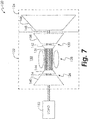
- gas turbine engine 120 is a turboshaft engine, although other types of gas turbine engines are certainly applicable to this disclosure.
- the gas turbine engine 120 may be used on an aircraft for generating thrust or power, on a rotorcraft for generating output shaft power, or in land-based operations for generating power as well.
- the gas turbine engine 120 may generally comprise a gas generator section 122 and a power turbine section 124.
- the gas generator section 122 may include a compressor section 126 where air is pressurized, a combustor 128 downstream of the compressor section which mixes and ignites the compressed air with fuel and thereby generates hot combustion gases, a turbine section 130 downstream of the combustor 128 for extracting power from the hot combustion gases, and an annular flow path 132 extending axially through each.
- the gas generator section 122 may comprise a single-spool configuration or a two-spool configuration.
- the gas generator section 122 comprises a two-spool configuration, particularly, a low spool 134 and a high spool 136.
- Mounted to the low spool 134 is a low pressure turbine 138 which drives a low pressure compressor 140.
- Mounted to the high spool 136 is a high pressure turbine 142 which drives a high pressure compressor 144. More or less than two spools may certainly be used in the gas generator section 122.
- the power turbine section 124 of the gas turbine engine 120 comprises a power turbine 146 mounted to a power turbine spool 148.
- the gas generator section 122 generates combustion gas that imparts torque to the power turbine spool 148 through the power turbine 146.
- the power turbine spool 148 may drive a load 150, such as, without limitation, a rotor, a turbo-pump, an electrical generator, a propeller, or other load.
- a gear box may multiply the torque or power from the power turbine spool 148 to the load 150.
- control system 160 for the gas turbine engine 120 is shown, according to an embodiment of the present disclosure.
- the control system 160 may comprise digital and/or analog elements.
- the control system 160 may comprise a non-transitory computer readable storage medium having stored thereon computer-executable instructions, such as, at least one computer processor.
- the control system 160 may include a load control module 162 in communication with a gas generator control module 164.
- the load and gas generator control modules 162, 164 are also in communication with the gas turbine engine 120 and load 150 (e.g., control units and/or sensors of the gas turbine engine 120 and load 150),
- the control system 160 may include a plurality of sensors operatively connected to the computer processor.
- the plurality of sensors may be disposed on the gas turbine engine 120 and load 150, generating signals indicative of operating parameters, such as, without limitation, a real-time power turbine speed and a real-time estimated power turbine torque.
- the load control module 162 and the gas generator control module 164 create a cascaded architecture of the control system 160 in order to manage power demand of the gas turbine engine 120 and rotor speed of the load 150.
- the load control module 162 may be in communication with the load 150
- the gas generator control module 164 may be in communication with the gas generator section 122 of the gas turbine engine 120.
- the load 150 is a combination of the power turbine and main rotor of the helicopter, although other loads are certainly possible
- the gas generator section 122 and the load 150 may also be in communication with each other.
- a model based estimation module 72 may be in communication with the gas generator control module 164 to provide the estimated current engine parameters 70 thereto, Adaptation logic module 75 provides the bandwidth W signal 73 to the model-based estimation module 72.
- the load control module 162 may receive a signal from the rotor load 150 indicative of current power turbine speed feedback (NP) in real-time.
- the load control module 162 may receive a desired power turbine operation speed (NP_ref) signal and a signal indicative of a collective lever angle command (CLA), that is, a collective pitch command, in real-time.
- the load control module 162 determines a torque request (Qpt_req) of the power turbine that will match the power turbine speed feedback signal (NP) in real-time to the desired power turbine speed (NP_ref) by control regulation. Tn so doing, the load control module 162 may maintain the power turbine 146 at a same rotor speed, or power turbine speed.
- the ratio between rotor speed and power turbine speed may be constant and may be determined by the gear ratio of the gear box coupling the rotor to the power turbine spool in an embodiment.
- a signal indicative of the determined torque request (Qpt_req) is then sent from the load control module 162 to the gas generator control module 164.
- the load control module 162 may employ inversion of a dynamic model.
- the load control module 162 may include a rotor model 268, an optimization formulator 270, and a constrained optimization solver 272.
- the rotor model 268 may model dynamic behavior of the rotor. It is to be understood that the model 268 may apply to other loads than the rotor, such as, without limitation, a turbo-pump, an electrical generator, a propeller, or the like.
- the load control module 162 may also employ other methods, such as, proportional integral plus feed-forward control methods as an approach for dynamically matching the desired power turbine operation speed (NP_ref) and the current power turbine speed feedback (NP) so as to determine the power turbine torque request signal (Qpt_req) for the load control module 162.
- proportional integral plus feed-forward control methods as an approach for dynamically matching the desired power turbine operation speed (NP_ref) and the current power turbine speed feedback (NP) so as to determine the power turbine torque request signal (Qpt_req) for the load control module 162.
- the rotor model 268 may be a linear or nonlinear (e.g., differential algebraic equations, possibly in numerical simulation form), physics and data-based model based at least in part on the power turbine speed feedback signal (NP) and collective lever angle command (CLA), In addition, the model 268 may be based on other inputs, such as operational inputs or environmental conditions including airframe speed, power turbine speed percentage, collective lever angle percentage, and autorotation mode (e.g., autorotation and autorotation recovery). Optimization formulator 270 may receive model system data from the rotor model 268, as well as the desired power turbine speed (NP_ref) and the power turbine speed feedback signal (NP). Based on those inputs, optimization formulator 270 may formulate an optimization problem for which optimization software will be able to solve as a numerically iterative process in real-time.
- NP_ref desired power turbine speed
- NP power turbine speed feedback signal
- Constrained optimization solver 272 may receive optimization data from the optimization formulator 270 in order to generate power turbine torque request (Qpt_req). Constrained optimization solver 272 may be a numerical iteration tool which finds a solution to the optimization problem formulated by optimization formulator 270. In addition, constrained optimization solver 272 may be constrained to certain limits, such as, a torque limit of the power turbine 124. In so doing, the load control module 162 utilizes constrained dynamic inversion of the rotor model in real-time to generate the torque request (Qpt_req).
- the gas generator control module 164 receives the power turbine torque request signal (Qpt_req) from the load control module 162.
- the gas generator control module 164 may receive a signal indicative of an estimated power turbine torque (Qpt_est) in real-time from the model-based estimation module 72.
- Other inputs such as, signals indicative of gas generator speed maximum limit (NG_max), gas turbine engine limits, and inlet guide vane (IGV) and stability bleed (BLD) schedules in real-time may also be received by the gas generator control module 164.
- the gas generator speed maximum limit (NG_max) signal may be sent to the gas generator control module 164 from a power rating module 173.
- Power rating module 173 receives a power lever angle signal (PLA) to generate gas generator speed maximum limit (NG_max) signal. Since gas generator speed is a function of power lever angle, power rating module 173 may utilize tables to generate the gas generator speed maximum limit (NG_max) signal based on the power lever angle (PLA) command.
- PPA power lever angle signal
- NG_max gas generator speed maximum limit
- inlet guide vane schedules may refer to the positioning of the low compressor stator vanes and the high compressor stator vanes.
- stability bleed schedules may refer to the positioning of the bleed valves between the compressors. Both the inlet guide vane angles and the stability bleed valves may be scheduled or adjusted as a function of corrected compressor speed in a way to manage compressor stability margin.
- the gas generator control module 164 determines a fuel flow (WF), inlet guide vane (IGV) schedules, and stability bleed (BLD) schedules of the gas generator section 122 that will deliver the power turbine torque request (Qpt_req) generated by the load control module 162.
- WF fuel flow
- IGV inlet guide vane
- BLD stability bleed
- the gas generator control module 164 manages multi-variable controls of the gas generator section 122 to quickly respond to power demand changes,
- a fuel flow signal (WF) indicative of the determined fuel flow, an inlet guide vane signal (IGV) indicative of the determined inlet guide vane schedules, and a stability bleed signal (BLD) indicative of the determined stability bleed schedules are sent from the gas generator control module 164 to the gas generator section 122 of the gas turbine engine 120,
- the fuel flow, inlet guide vane positions, and stability bleed valves of the gas generator section 122 are then adjusted according to the signals received from the gas generator control module 164,
- the gas generator control module 164 In order to generate the fuel flow (WF), inlet guide vane schedules (IGV), and stability bleed schedules (BLD), the gas generator control module 164 employs a dynamical inversion approach,
- the gas generator control module 164 may include a gas generator model 274, an optimization formulator 276, and a constrained optimization solver 278.
- the gas generator model 274 may describe dynamic behavior of the gas generator.
- the gas generator model 274 may be a linear or nonlinear (e.g., differential algebraic equations, possibly in numerical simulation form), physics and data-based model based at least in part on the power turbine speed feedback signal (NP) and operational inputs.
- the operational inputs may include, but not be limited to an altitude of the airframe (ambient pressure over standard day pressure) and a corrected speed of the rotor spool.
- Optimization formulator 276 may receive collect real-time data to formulate an optimization cost function (in part based on an error between a desired goal and the current state of a variable), and to formulate optimization constraints (in part based on an operational boundary of a variable in real physics). To do so, the optimization formulator 276 may use the power turbine torque request (Qpt_req) and the estimated power turbine torque signal (Qpt_est) to determine a cost function of the power turbine torque goal. The optimization formulator 276 may also use the IGV and BLD schedules together with the system data from the gas-generator model 274 to determine a cost function of the actuation goal.
- the optimization formulator 276 may further use the system data from the gas-generator model 274 together with the engine limits of the gas turbine engine 20, such as, without limitation, a rotor speed limit, a compressor stall limit, a lean blowout limit, a temperature limit, a pressure limit, or the like, as the optimization constraint data in formulating an optimization problem. Based on those inputs, optimization formulator 276 may formulate an optimization problem for which optimization software will be able to solve as a numerically iterative process in real-time. Constrained optimization solver 278 may receive optimization data From the optimization formulator 276 in order to generate the requested fuel flow, inlet guide vane schedules, and stability bleed schedules (WF, IGV & BLD request).
- WF stability bleed schedules
- Constrained optimization solver 278 may be a numerical iteration tool which finds a solution to the optimization problem formulated by optimization formulator 276 using a model-based constrained dynamic inversion (such as that disclosed in U.S. Patent Publication US 2013/0158680 A1 , to name one non-limiting example).
- Real-time implementation of the gas generator control module 164 generates values for fuel flow, inlet guide vane schedules, and stability bleed schedules that deliver a torque of the power turbine section 24 that is proximate or equal to the torque request (Qpt_req) and within the limits of the gas turbine engine 120.
- the control system 160 may receive the real-time collective lever angle command (CLA) and the real-time power turbine speed (NP) signal.
- the load control module 162 of the control system 160 generates the torque request (Qpt_req) based at least in part on the real-time collective lever angle (CLA) command and the real-time power turbine speed (NP) signal, at block 284.
- a bandwidth signal 73 is generated by the adaptation logic 75.
- the bandwidth signal 73 is used by the model-based estimation module 72 to generate estimated current engine parameters at block 288,
- the gas generator control module 164 of the control system 160 generates the fuel flow (WF), the inlet guide vane (IGV), and the stability bleed (BLD) signals based at least in part on the generated torque request (Qpt__req) by the load control module 162 and the estimated current engine parameters generated by the model-based estimation module 72.
- the gas turbine engine 120 is operated according to the generated fuel flow (WF), inlet guide vane (IGV), and stability bleed (BLD) signals at block 292. More specifically, the gas generator control module 164 sends the fuel flow, inlet guide vane, and stability bleed signals to the gas generator section 122 of the gas turbine engine 120 in order to control the torque output of the power turbine section 124.
- the described disclosure provides a multi-variable control system embedded with an adaptive estimation module for a gas turbine engine.
- the presently disclosed control systems and methods may find application in the control of a turboshaft engine, where they allow for the gas turbine engine to promptly deliver a requested change in power demand during flight maneuvers, while at the same time, minimizing power turbine speed excursion caused by a rotor load at various power levels.
- the disclosed system and method coordinate multi-variable controls, i.e., fuel flow and ingle guide vane schedules, in order to meet the power demand under engine operation limits.
- the cascaded architecture of the disclosed control system includes a load control module for power turbine control and a gas generator control module for gas generator control. Based on a collective lever angle command from a pilot of the aircraft, the load control module calculates a power turbine torque request based upon a power turbine speed error, thereby minimizing the power turbine speed excursion. In order to minimize error between the calculated power turbine torque request and an estimated real-time power turbine torque, the gas generator control module utilizes a real-time implementation of a dynamic model for the gas generator to regulate both fuel flow and inlet guide vanes of the gas turbine engine.
- the control system and method disclosed herein By using the control system and method disclosed herein, rotor speed excursion is reduced during quick changes in load or power demand, thereby providing improved flight handling quality at various power levels, In addition, more consistent compressor stall/surge protection is provided due to the limits or constraints incorporated into the gas generator control module, Furthermore, as applied to a turboshaft engine, the multi-variable control system with cascaded architecture affords smoother transients between autorotation and recovery. Moreover, the disclosed system and method provides improved integration with different airframes in load changes.
Claims (15)
- Steuerungssystem (60) für einen Gasturbinenmotor (20), wobei das Steuerungssystem Folgendes umfasst:einen ersten Sensor, der konfiguriert ist, um ein Schubhebelwinkelsignal (SHW) zu erzeugen, das einen Schubhebelwinkel anzeigt, der von dem Gasturbinenmotor verlangt wird;einen zweiten Sensor, der in Kommunikation mit dem Gasturbinenmotor steht und konfiguriert ist, um wenigstens ein Betriebsparametersignal (78) zu erzeugen, das wenigstens einen Betriebsparameter des Gasturbinenmotors anzeigt;ein Leistungsbewertungsmodul (68), das konfiguriert ist, um das Schubhebelwinkelsignal zu empfangen und wenigstens ein Zielsignal (66) zu erzeugen, das ein Betriebspunktziel für den Gasturbinenmotor anzeigt;ein Adaptionslogikmodul (75), das konfiguriert ist, um das wenigstens eine Zielsignal und das wenigstens eine Betriebsparametersignal zu empfangen und ein Bandbreitensignal (73) zu erzeugen, das einen Fehler zwischen dem wenigstens einen Zielsignal und dem wenigstens einen Betriebsparametersignal anzeigt;ein modellbasiertes Schätzmodul (72), das konfiguriert ist, um das Bandbreitensignal zu empfangen und ein Motorschätzsignal (70) zu erzeugen, das wenigstens zum Teil basierend auf dem Bandbreitensignal geschätzte aktuelle Motorparameter des Gasturbinenmotors anzeigt; undein modellbasiertes Steuerungsmodul (64), das konfiguriert ist, um das wenigstens eine Betriebsparametersignal, das wenigstens eine Zielsignal und das Motorschätzsignal zu empfangen und wenigstens zum Teil basierend auf dem empfangenen wenigstens einen Betriebsparametersignal, dem wenigstens einen Zielsignal und dem Motorschätzsignal wenigstens eines zu bestimmen von einem Kraftstofffluss, Einlassleitschaufelzeitplänen und Stabilitätsablasszeitplänen und Effektorsignale an einen Gasgenerator (22) des Gasturbinenmotors zu senden, um den Gasgenerator gemäß von wenigstens einem von dem bestimmten Kraftstofffluss, den Einlassleitschaufelzeitplänen und den Stabilitätsablasszeitplänen zu steuern.
- Steuerungssystem nach Anspruch 1, wobei das modellbasierte Steuerungsmodul konfiguriert ist, um eine modellbasierte beschränkte dynamische Inversionsmethodologie zu verwenden, um wenigstens eines zu bestimmen von dem Kraftstofffluss, den Einlassleitschaufelzeitplänen und den Stabilitätsablasszeitplänen, und/oder wobei das modellbasierte Steuerungsmodul konfiguriert ist, um Signale zu empfangen, die Betriebsgrenzwerte des Gasturbinenmotors, Einlassleitschaufelzeitpläne in Echtzeit und Stabilitätsablasszeitpläne in Echtzeit anzeigen.
- Steuerungssystem nach Anspruch 1 oder 2, wobei das wenigstens eine Betriebsparametersignal wenigstens eines umfasst von einer Drehzahl, einer Leistung, einem Drehmoment und einem Schub des Gasturbinenmotors in Echtzeit oder wobei das wenigstens eine Betriebsparametersignal eine aktuelle Drehzahl, eine aktuelle Leistung, ein aktuelles Drehmoment und/oder einen aktuellen Schub des Gasturbinenmotors umfasst.
- Steuerungssystem nach einem der vorhergehenden Ansprüche, wobei das Leistungsbewertungsmodul vorbestimmte Tabellen einsetzt, um das wenigstens eine Zielsignal zu erzeugen.
- Steuerungssystem nach einem der vorhergehenden Ansprüche, wobei das Adaptionslogikmodul Folgendes umfasst:einen Komparator (81), der konfiguriert ist, um ein Fehlersignal zu bestimmen, das einen Unterschied zwischen dem wenigstens einen Zielsignal und dem wenigstens einen Betriebsparametersignal umfasst;einen Tiefpassfilter (84), der konfiguriert ist, um das Fehlersignal zu empfangen und ein gefiltertes Fehlersignal zu produzieren;einen Integrator (88), der konfiguriert ist, um das gefilterte Fehlersignal zu empfangen und ein integriertes Fehlersignal zu produzieren; undeine Nachschlagetabelle (92), die konfiguriert ist, um wenigstens zum Teil basierend auf zumindest einem von dem gefilterten Fehlersignal und dem integrierten Fehlersignal ein Bandbreitensignal zu produzieren.
- Steuerungssystem nach einem der vorhergehenden Ansprüche, wobei das modellbasierte Schätzmodul Folgendes umfasst:einen Komparator (94), der konfiguriert ist, um ein Fehlersignal zu bestimmen, das einen Unterschied zwischen dem wenigstens einen wenigstens einen Betriebsparametersignal und einem Messwert des Motorschätzsignals umfasst;einen Vorspannschätzer (96), der konfiguriert ist, um das Fehlersignal und das Bandbreitensignal zu empfangen und um ein Vorspannsignal zu produzieren, wobei der Vorspannschätzer vorzugsweise eines umfasst von einem Tiefpassfilter, einem Kalman-Filter, einem neuronalen Netzwerk, einer optimalen Schätzung, einer rekursiven Systemidentifikation, einem asymmetrischen Beobachter und einer adaptiven Logik basierend auf der adaptiven Steuerungstheorie L1;ein statusvariables Modell (102), das konfiguriert ist, um ein Vorhersagesignal zu produzieren, das einen aktuellen Status des Gasturbinenmotors anzeigt;eine Vorhersagesignal-Vorspannvorrichtung (100), die konfiguriert ist, um das Vorspannsignal und das Vorhersagesignal zu empfangen und ein Signal zum vorhergesagten Parameter zu produzieren, das den aktuellen Status des Gasturbinenmotors anzeigt; undeine Datenspeichervorrichtung (108), die konfiguriert ist, um das Signal zum vorhergesagte Parameter zu speichern und das Motorschätzsignal zu produzieren.
- Steuerungssystem nach einem der vorhergehenden Ansprüche, wobei das modellbasierte Schätzmodul Folgendes umfasst:ein statusvariables Modell (102), das konfiguriert ist, um ein Vorhersagesignal zu produzieren, das einen aktuellen Status des Gasturbinenmotors anzeigt;einen Komparator (94), der konfiguriert ist, um ein Fehlersignal zu bestimmen, das einen Unterschied zwischen dem Vorhersagesignal und einer Rückkopplung des Motorschätzsignals umfasst;einen Tiefpassfilter (110), der konfiguriert ist, um das Fehlersignal und das Bandbreitensignal zu empfangen und ein Vorspannsignal zu produzieren;eine Vorhersagesignal-Vorspannvorrichtung (100), die konfiguriert ist, um das Vorspannsignal und das Vorhersagesignal zu empfangen und das Motorschätzsignal zu produzieren.
- Steuerungssystem (160) für einen Gasturbinenmotor (120), der eine Leistungsturbine (124) einschließt, wobei das Steuerungssystem Folgendes umfasst:einen Sensor, der in Kommunikation mit dem Gasturbinenmotor steht und konfiguriert ist, um wenigsten ein Betriebsparametersignal (Qpt) zu erzeugen, das wenigstens einen Betriebsparameter des Gasturbinenmotors anzeigt;ein Laststeuerungsmodul (162), das konfiguriert ist, um ein Signal zur gewünschten Leistungsturbinendrehzahl zu empfangen und eine Leistungsturbinendrehmomentanfrage (Qpt_Anf) auszugeben; undein Adaptionslogikmodul (75), das konfiguriert ist, um das Signal zur gewünschten Leistungsturbinendrehzahl und das wenigstens eine Betriebsparametersignal zu empfangen und ein Bandbreitensignal (73) zu erzeugen, das einen Fehler zwischen dem Signal zur gewünschten Leistungsturbinendrehzahl und dem wenigstens einen Betriebsparametersignal anzeigt;ein modellbasiertes Schätzmodul (72), das konfiguriert ist, um das Bandbreitensignal zu empfangen und um ein Motorschätzsignal (70) zu erzeugen, das wenigstens zum Teil basierend auf dem Bandbreitensignal geschätzte aktuelle Motorparameter des Gasturbinenmotors anzeigt; undein Gasgenerator-Steuerungsmodul (164), das konfiguriert ist, um die Leistungsturbinendrehmomentanfrage (Qpt_Anf) von dem Laststeuerungsmodul und die geschätzten aktuellen Motorparameter von dem modellbasierten Schätzmodul zu empfangen, wenigstens zum Teil basierend auf der empfangenen Leistungsturbinendrehmomentantrage (Qpt_Anf) und den geschätzten aktuellen Motorparametern wenigstens eines zu bestimmen von einem Kraftstofffluss, Einlassleitschaufelzeitplänen und Stabilitätsablasszeitplänen und Signale an einen Gasgenerator (122) des Gasturbinenmotors zu senden, um den Gasturbinenmotor gemäß wenigstens einem von dem bestimmten Kraftstofffluss, den Einlassleitschaufelzeitplänen und den Stabilitätsablasszeitplänen zu steuern.
- Steuerungssystem nach Anspruch 8, wobei das Gasgenerator-Steuerungsmodul konfiguriert ist, um eine modellbasierte beschränkte dynamische Inversionsmethodologie zu verwenden, um wenigstens eines zu bestimmen von dem Kraftstofffluss, den Einlassleitschaufelzeitplänen und den Stabilitätsablasszeitplänen, und wobei vorzugsweise das Gasgenerator-Steuerungsmodul Folgendes umfasst:ein Gasgeneratormodell (274), das konfiguriert ist, um wenigstens zum Teil basierend auf dem wenigstens einen Betriebsparameter Systemdaten zu bestimmen;ein Optimierungsformulierungsmodul (276), das konfiguriert ist, um wenigstens zum Teil basierend auf den Systemdaten Optimierungsdaten zu bestimmen; undeinen beschränkten Optimierungsgleichungslöser (278), der konfiguriert ist, um die modellbasierte beschränkte dynamische Inversion der Optimierungsdaten zu verwenden, um wenigstens eines zu bestimmen von dem Kraftstofffluss, den Einlassleitschaufelzeitplänen und den Stabilitätsablasszeitplänen.
- Steuerungssystem nach Anspruch 8 oder 9, wobei das Laststeuerungsmodul Folgendes umfasst:ein Rotormodell (268), das konfiguriert ist, um ein kollektives Hebelwinkelbefehlssignal in Echtzeit zu empfangen und Modellsystemdaten zu bestimmen;einen Optimierungsformulierer (270), der konfiguriert ist, um die Modellsystemdaten zu empfangen und Optimierungsdaten zu produzieren; undeinen beschränkten Optimierungsgleichungslöser (272), der konfiguriert ist, um die Optimierungsdaten zu empfangen und die Leistungsturbinendrehmomentanfrage (Qpt_Anf) zu erzeugen.
- Steuerungssystem nach Anspruch 8, 9 oder 10, wobei eine Last (150) von einem Rotor produziert wird, der mit der Leistungsturbine gekoppelt ist.
- Steuerungssystem nach einem der Ansprüche 8 bis 11, wobei das wenigstens eine Betriebsparametersignal eine aktuelle Motordrehzahl, eine aktuelle Leistung und/oder einen aktuellen Schub des Gasturbinenmotors umfasst.
- Steuerungssystem nach einem der Ansprüche 8 bis 12, wobei das Adaptionslogikmodul Folgendes umfasst:einen Komparator (81), der konfiguriert ist, um ein Fehlersignal zu bestimmen, das einen Unterschied zwischen dem Signal zur gewünschten Leistungsturbinendrehzahl und dem wenigstens einen Betriebsparametersignal umfasst;einen Tiefpassfilter (84), der konfiguriert ist, um das Fehlersignal zu empfangen und ein gefiltertes Fehlersignal zu produzieren;einen Integrator (88), der konfiguriert ist, um das gefilterte Fehlersignal zu empfangen und ein integriertes Fehlersignal zu produzieren; undeine Nachschlagetabelle (92), die konfiguriert ist, um wenigstens zum Teil basierend auf wenigstens einem von dem gefilterten Fehlersignal und dem integrierten Fehlersignal das Bandbreitensignal zu produzieren.
- Steuerungssystem nach einem der Ansprüche 8 bis 13, wobei das modellbasierte Schätzmodul Folgendes umfasst:einen Komparator (94), der konfiguriert ist, um ein Fehlersignal zu bestimmen, das einen Unterschied zwischen dem wenigstens einen Betriebsparametersignal und einer Rückkopplung des Motorschätzsignals umfasst;einen Vorspannschätzer (96), der konfiguriert ist, um das Fehlersignal und das Bandbreitensignal zu empfangen und um ein Vorspannsignal zu produzieren, wobei der Vorspannschätzer vorzugsweise eines umfasst von einem Tiefpassfilter, einem Kalman-Filter, einem neuronalen Netzwerk, einer optimalen Schätzung, einer rekursiven Systemidentifikation, einem asymmetrischen Beobachter und einer adaptiven Logik basierend auf der adaptiven Steuerungstheorie L1;ein statusvariables Modell (102), das konfiguriert ist, um ein Vorhersagesignal zu produzieren, das einen aktuellen Status des Gasturbinenmotors anzeigt;eine Vorhersagesignal-Vorspannvorrichtung (100), die konfiguriert ist, um das Vorspannsignal und das Vorhersagesignal zu empfangen und ein Signal zum vorhergesagten Parameter zu produzieren, das den aktuellen Status des Gasturbinenmotors anzeigt; undeine Datenspeichervorrichtung (108), die konfiguriert ist, um das Signal zum vorhergesagten Parameter zu speichern und das Motorschätzsignal zu produzieren.
- Steuerungssystem nach einem der Ansprüche 8 bis 14, wobei das modellbasierte Schätzmodul Folgendes umfasst:ein statusvariables Modell (102), das konfiguriert ist, um ein Vorhersagesignal zu produzieren, das einen aktuellen Status des Gasturbinenmotors anzeigt;einen Komparator (94), der konfiguriert ist, um ein Fehlersignal zu bestimmen, das einen Unterschied zwischen dem Vorhersagesignal und einer Rückkopplung des Motorschätzsignals anzeigt;einen Tiefpassfilter (110), der konfiguriert ist, um das Fehlersignal und das Bandbreitensignal zu empfangen und das Vorspannsignal zu produzieren; undeine Vorhersagesignal-Vorspannvorrichtung (100), die konfiguriert ist, um das Vorspannsignal und das Vorhersagesignal zu empfangen und das Motorschätzsignal zu produzieren.
Applications Claiming Priority (1)
| Application Number | Priority Date | Filing Date | Title |
|---|---|---|---|
| US14/599,921 US9732625B2 (en) | 2015-01-19 | 2015-01-19 | System and method for controlling a gas turbine engine |
Publications (2)
| Publication Number | Publication Date |
|---|---|
| EP3045982A1 EP3045982A1 (de) | 2016-07-20 |
| EP3045982B1 true EP3045982B1 (de) | 2018-11-07 |
Family
ID=55221310
Family Applications (1)
| Application Number | Title | Priority Date | Filing Date |
|---|---|---|---|
| EP16151977.2A Active EP3045982B1 (de) | 2015-01-19 | 2016-01-19 | System und verfahren zur steuerung eines gasturbinenmotors |
Country Status (2)
| Country | Link |
|---|---|
| US (1) | US9732625B2 (de) |
| EP (1) | EP3045982B1 (de) |
Families Citing this family (29)
| Publication number | Priority date | Publication date | Assignee | Title |
|---|---|---|---|---|
| JP6260437B2 (ja) * | 2014-04-28 | 2018-01-17 | 株式会社Ihi | 動的システムの推定装置及び方法 |
| US20170159574A1 (en) * | 2015-12-04 | 2017-06-08 | General Electric Company | Adaptive Engine Model Torque Splitting Optimization |
| US11112118B2 (en) * | 2016-06-27 | 2021-09-07 | General Electric Company | Gas turbine lower heating value methods and systems |
| US10473038B2 (en) | 2016-10-26 | 2019-11-12 | Pratt & Whitney Canada Corp. | Power plant thrust management system for turboprop engines |
| US10240544B2 (en) | 2016-10-27 | 2019-03-26 | Rolls-Royce Corporation | Adaptive controller using unmeasured operating parameter |
| US10309330B2 (en) * | 2016-10-27 | 2019-06-04 | Rolls-Royce Corporation | Model reference adaptive controller |
| US10759528B2 (en) * | 2016-11-15 | 2020-09-01 | Sikorsky Aircraft Corporation | Model following control for torque and rotor speed |
| US10604268B2 (en) * | 2017-02-22 | 2020-03-31 | Pratt & Whitney Canada Corp. | Autothrottle control for turboprop engines |
| CN107035430B (zh) * | 2017-05-26 | 2019-11-08 | 国家电网公司 | 一种基于大数据分析的汽轮机阀门流量特性参数优化方法 |
| US10822104B2 (en) | 2017-08-29 | 2020-11-03 | Pratt & Whitney Canada Corp. | Variable geometries transient control logic |
| US10822996B2 (en) | 2018-03-12 | 2020-11-03 | General Electric Company | Gas turbine engine health determination |
| US11092136B2 (en) * | 2018-05-04 | 2021-08-17 | Raytheon Technologies Corporation | Systems and methods for optimal speed protection for power turbine governing |
| WO2019237320A1 (zh) * | 2018-06-15 | 2019-12-19 | 大连理工大学 | 一种基于模型预测的航空发动机在线优化及多变量控制设计方法 |
| DE102018115354A1 (de) * | 2018-06-26 | 2020-01-02 | Rolls-Royce Deutschland Ltd & Co Kg | Vorrichtung und Verfahren zur Bestimmung mindestens eines Rotationsparameters einer rotierenden Vorrichtung |
| US11486316B2 (en) | 2018-09-13 | 2022-11-01 | Pratt & Whitney Canada Corp. | Method and system for adjusting a variable geometry mechanism |
| US10961921B2 (en) | 2018-09-19 | 2021-03-30 | Pratt & Whitney Canada Corp. | Model-based control system and method for a turboprop engine |
| US10767506B2 (en) * | 2018-10-17 | 2020-09-08 | Raytheon Technologies Corporation | Model predictive control sub-system hydraulic flow management |
| US10655494B2 (en) * | 2018-10-17 | 2020-05-19 | United Technologies Corporation | Model predictive control sub-system power management |
| US11391218B2 (en) * | 2019-03-22 | 2022-07-19 | Pratt & Whitney Canada Corp. | Method and system for setting power of an aircraft engine |
| US11047253B2 (en) | 2019-05-03 | 2021-06-29 | Raytheon Technologies Corporation | Model-based rotor speed keep out zone control |
| DE102019207256B4 (de) * | 2019-05-17 | 2023-11-09 | Rolls-Royce Deutschland Ltd & Co Kg | Vorrichtung und Verfahren zur Eigendiagnose einer Überwachungsvorrichtung eines Bauteils, sowie Gasturbinentriebwerk mit einer Vorrichtung zur Eigendiagnose einer Überwachungsvorrichtung eines Bauteils |
| US11346290B2 (en) * | 2020-02-21 | 2022-05-31 | Raytheon Technologies Corporation | Speed limiting for power turbine governing and protection in a turboshaft engine |
| CN111456857B (zh) * | 2020-04-04 | 2023-02-28 | 西北工业大学 | 航空发动机降保守性增益调度二自由度h∞控制器 |
| CN111734533B (zh) * | 2020-05-28 | 2022-09-23 | 北京仿真中心 | 一种基于涡扇发动机的模型预测方法及系统 |
| CN111856933B (zh) * | 2020-07-06 | 2022-08-09 | 大连理工大学 | 一种考虑不确定性的航空发动机自适应控制器设计方法 |
| CN113126599B (zh) * | 2021-06-18 | 2021-08-20 | 成都康拓兴业科技有限责任公司 | 一种进气道电气控制测试系统 |
| CN114265368B (zh) * | 2021-12-07 | 2023-07-25 | 中国航发控制系统研究所 | 航空发动机伺服控制系统组合状态自适应估计方法 |
| US11920521B2 (en) | 2022-02-07 | 2024-03-05 | General Electric Company | Turboshaft load control using feedforward and feedback control |
| CN116979623B (zh) * | 2023-09-22 | 2023-12-08 | 湖南江河能源科技股份有限公司 | 一种水电站自主优化发电控制策略 |
Family Cites Families (8)
| Publication number | Priority date | Publication date | Assignee | Title |
|---|---|---|---|---|
| US7376504B2 (en) * | 2001-11-15 | 2008-05-20 | Goodrich Pump & Engine Control Systems, Inc. | Method of engine surge discrimination |
| US6823675B2 (en) * | 2002-11-13 | 2004-11-30 | General Electric Company | Adaptive model-based control systems and methods for controlling a gas turbine |
| JP4511873B2 (ja) | 2004-03-31 | 2010-07-28 | 本田技研工業株式会社 | ガスタービン・エンジンのセンサ故障検知装置 |
| US7245040B2 (en) * | 2005-07-15 | 2007-07-17 | Honeywell International, Inc. | System and method for controlling the frequency output of dual-spool turbogenerators under varying load |
| US7904282B2 (en) * | 2007-03-22 | 2011-03-08 | General Electric Company | Method and system for fault accommodation of machines |
| US8315741B2 (en) | 2009-09-02 | 2012-11-20 | United Technologies Corporation | High fidelity integrated heat transfer and clearance in component-level dynamic turbine system control |
| US9494925B2 (en) | 2011-12-20 | 2016-11-15 | United Technologies Corporation | Hybrid control system |
| US9441547B2 (en) | 2014-06-02 | 2016-09-13 | United Technologies Corporation | Model-based optimal control for stall margin limit protection in an aircraft engine |
-
2015
- 2015-01-19 US US14/599,921 patent/US9732625B2/en active Active
-
2016
- 2016-01-19 EP EP16151977.2A patent/EP3045982B1/de active Active
Non-Patent Citations (1)
| Title |
|---|
| None * |
Also Published As
| Publication number | Publication date |
|---|---|
| US9732625B2 (en) | 2017-08-15 |
| US20160208639A1 (en) | 2016-07-21 |
| EP3045982A1 (de) | 2016-07-20 |
Similar Documents
| Publication | Publication Date | Title |
|---|---|---|
| EP3045982B1 (de) | System und verfahren zur steuerung eines gasturbinenmotors | |
| US10316760B2 (en) | Turboshaft engine control | |
| US10113487B2 (en) | Cascaded multi-variable control system for a turboshaft engine | |
| Garg | Aircraft turbine engine control research at NASA Glenn research center | |
| May et al. | A high-fidelity simulation of a generic commercial aircraft engine and controller | |
| EP3045696B1 (de) | System und verfahren zur leistungsverwaltung in einem wellentriebwerk | |
| EP3147220A1 (de) | Systeme und verfahren zur einhebel-turbopropsteuerung unter verwendung drehmomentbasierter und leistungsbasierter zeitplanung | |
| US7861578B2 (en) | Methods and systems for estimating operating parameters of an engine | |
| US10794286B2 (en) | Method and system for modulated turbine cooling as a function of engine health | |
| US10711734B2 (en) | Optimal thrust control of an aircraft engine | |
| EP3550127B1 (de) | Systeme und verfahren zur leistungsturbinenregelung | |
| US20180258785A1 (en) | Adaptive Active Clearance Control Logic | |
| EP3705706B1 (de) | Kraftstoffregelungssystem | |
| EP3244040B1 (de) | Multivariable treibstoffkontrolle und -schätzer (mfce) zur verhinderung von brennkammerausblasen | |
| EP3073102B1 (de) | Steuerungsschema mit turbine mit verstellbarem querschnitt und schubdüse zur reduzierung des luftwiderstands | |
| EP3279450B1 (de) | System und verfahren für einen motorenregler auf basis der beschleunigungsleistung | |
| US20200307831A1 (en) | Engine thrust rating architecture and processes | |
| CN110199102B (zh) | 燃气涡轮发动机燃料控制系统和方法 | |
| US11649763B1 (en) | Rating control architecture and method for hybrid electric engine | |
| Viassolo et al. | Advanced controls for fuel consumption and time-on-wing optimization in commercial aircraft engines | |
| BURCHAM, JR et al. | The value of early flight evaluation of propulsion concepts using the NASA F-15 research airplane |
Legal Events
| Date | Code | Title | Description |
|---|---|---|---|
| PUAI | Public reference made under article 153(3) epc to a published international application that has entered the european phase |
Free format text: ORIGINAL CODE: 0009012 |
|
| AK | Designated contracting states |
Kind code of ref document: A1 Designated state(s): AL AT BE BG CH CY CZ DE DK EE ES FI FR GB GR HR HU IE IS IT LI LT LU LV MC MK MT NL NO PL PT RO RS SE SI SK SM TR |
|
| AX | Request for extension of the european patent |
Extension state: BA ME |
|
| RAP1 | Party data changed (applicant data changed or rights of an application transferred) |
Owner name: UNITED TECHNOLOGIES CORPORATION |
|
| STAA | Information on the status of an ep patent application or granted ep patent |
Free format text: STATUS: REQUEST FOR EXAMINATION WAS MADE |
|
| 17P | Request for examination filed |
Effective date: 20170120 |
|
| RBV | Designated contracting states (corrected) |
Designated state(s): AL AT BE BG CH CY CZ DE DK EE ES FI FR GB GR HR HU IE IS IT LI LT LU LV MC MK MT NL NO PL PT RO RS SE SI SK SM TR |
|
| REG | Reference to a national code |
Ref country code: DE Ref legal event code: R079 Ref document number: 602016006852 Country of ref document: DE Free format text: PREVIOUS MAIN CLASS: G05B0013040000 Ipc: F01D0017060000 |
|
| GRAP | Despatch of communication of intention to grant a patent |
Free format text: ORIGINAL CODE: EPIDOSNIGR1 |
|
| STAA | Information on the status of an ep patent application or granted ep patent |
Free format text: STATUS: GRANT OF PATENT IS INTENDED |
|
| RIC1 | Information provided on ipc code assigned before grant |
Ipc: F01D 21/00 20060101ALI20180406BHEP Ipc: F01D 17/10 20060101ALI20180406BHEP Ipc: G05B 13/04 20060101ALI20180406BHEP Ipc: F01D 17/06 20060101AFI20180406BHEP |
|
| INTG | Intention to grant announced |
Effective date: 20180424 |
|
| GRAS | Grant fee paid |
Free format text: ORIGINAL CODE: EPIDOSNIGR3 |
|
| GRAJ | Information related to disapproval of communication of intention to grant by the applicant or resumption of examination proceedings by the epo deleted |
Free format text: ORIGINAL CODE: EPIDOSDIGR1 |
|
| GRAL | Information related to payment of fee for publishing/printing deleted |
Free format text: ORIGINAL CODE: EPIDOSDIGR3 |
|
| STAA | Information on the status of an ep patent application or granted ep patent |
Free format text: STATUS: REQUEST FOR EXAMINATION WAS MADE |
|
| GRAR | Information related to intention to grant a patent recorded |
Free format text: ORIGINAL CODE: EPIDOSNIGR71 |
|
| STAA | Information on the status of an ep patent application or granted ep patent |
Free format text: STATUS: GRANT OF PATENT IS INTENDED |
|
| GRAA | (expected) grant |
Free format text: ORIGINAL CODE: 0009210 |
|
| STAA | Information on the status of an ep patent application or granted ep patent |
Free format text: STATUS: THE PATENT HAS BEEN GRANTED |
|
| INTC | Intention to grant announced (deleted) | ||
| INTG | Intention to grant announced |
Effective date: 20180924 |
|
| AK | Designated contracting states |
Kind code of ref document: B1 Designated state(s): AL AT BE BG CH CY CZ DE DK EE ES FI FR GB GR HR HU IE IS IT LI LT LU LV MC MK MT NL NO PL PT RO RS SE SI SK SM TR |
|
| REG | Reference to a national code |
Ref country code: GB Ref legal event code: FG4D |
|
| REG | Reference to a national code |
Ref country code: CH Ref legal event code: EP Ref country code: AT Ref legal event code: REF Ref document number: 1062299 Country of ref document: AT Kind code of ref document: T Effective date: 20181115 |
|
| REG | Reference to a national code |
Ref country code: DE Ref legal event code: R096 Ref document number: 602016006852 Country of ref document: DE |
|
| REG | Reference to a national code |
Ref country code: IE Ref legal event code: FG4D |
|
| REG | Reference to a national code |
Ref country code: NL Ref legal event code: MP Effective date: 20181107 |
|
| REG | Reference to a national code |
Ref country code: LT Ref legal event code: MG4D |
|
| REG | Reference to a national code |
Ref country code: AT Ref legal event code: MK05 Ref document number: 1062299 Country of ref document: AT Kind code of ref document: T Effective date: 20181107 |
|
| PG25 | Lapsed in a contracting state [announced via postgrant information from national office to epo] |
Ref country code: IS Free format text: LAPSE BECAUSE OF FAILURE TO SUBMIT A TRANSLATION OF THE DESCRIPTION OR TO PAY THE FEE WITHIN THE PRESCRIBED TIME-LIMIT Effective date: 20190307 Ref country code: FI Free format text: LAPSE BECAUSE OF FAILURE TO SUBMIT A TRANSLATION OF THE DESCRIPTION OR TO PAY THE FEE WITHIN THE PRESCRIBED TIME-LIMIT Effective date: 20181107 Ref country code: AT Free format text: LAPSE BECAUSE OF FAILURE TO SUBMIT A TRANSLATION OF THE DESCRIPTION OR TO PAY THE FEE WITHIN THE PRESCRIBED TIME-LIMIT Effective date: 20181107 Ref country code: HR Free format text: LAPSE BECAUSE OF FAILURE TO SUBMIT A TRANSLATION OF THE DESCRIPTION OR TO PAY THE FEE WITHIN THE PRESCRIBED TIME-LIMIT Effective date: 20181107 Ref country code: NO Free format text: LAPSE BECAUSE OF FAILURE TO SUBMIT A TRANSLATION OF THE DESCRIPTION OR TO PAY THE FEE WITHIN THE PRESCRIBED TIME-LIMIT Effective date: 20190207 Ref country code: LV Free format text: LAPSE BECAUSE OF FAILURE TO SUBMIT A TRANSLATION OF THE DESCRIPTION OR TO PAY THE FEE WITHIN THE PRESCRIBED TIME-LIMIT Effective date: 20181107 Ref country code: BG Free format text: LAPSE BECAUSE OF FAILURE TO SUBMIT A TRANSLATION OF THE DESCRIPTION OR TO PAY THE FEE WITHIN THE PRESCRIBED TIME-LIMIT Effective date: 20190207 Ref country code: LT Free format text: LAPSE BECAUSE OF FAILURE TO SUBMIT A TRANSLATION OF THE DESCRIPTION OR TO PAY THE FEE WITHIN THE PRESCRIBED TIME-LIMIT Effective date: 20181107 Ref country code: ES Free format text: LAPSE BECAUSE OF FAILURE TO SUBMIT A TRANSLATION OF THE DESCRIPTION OR TO PAY THE FEE WITHIN THE PRESCRIBED TIME-LIMIT Effective date: 20181107 |
|
| PG25 | Lapsed in a contracting state [announced via postgrant information from national office to epo] |
Ref country code: PT Free format text: LAPSE BECAUSE OF FAILURE TO SUBMIT A TRANSLATION OF THE DESCRIPTION OR TO PAY THE FEE WITHIN THE PRESCRIBED TIME-LIMIT Effective date: 20190307 Ref country code: AL Free format text: LAPSE BECAUSE OF FAILURE TO SUBMIT A TRANSLATION OF THE DESCRIPTION OR TO PAY THE FEE WITHIN THE PRESCRIBED TIME-LIMIT Effective date: 20181107 Ref country code: NL Free format text: LAPSE BECAUSE OF FAILURE TO SUBMIT A TRANSLATION OF THE DESCRIPTION OR TO PAY THE FEE WITHIN THE PRESCRIBED TIME-LIMIT Effective date: 20181107 Ref country code: GR Free format text: LAPSE BECAUSE OF FAILURE TO SUBMIT A TRANSLATION OF THE DESCRIPTION OR TO PAY THE FEE WITHIN THE PRESCRIBED TIME-LIMIT Effective date: 20190208 Ref country code: SE Free format text: LAPSE BECAUSE OF FAILURE TO SUBMIT A TRANSLATION OF THE DESCRIPTION OR TO PAY THE FEE WITHIN THE PRESCRIBED TIME-LIMIT Effective date: 20181107 Ref country code: RS Free format text: LAPSE BECAUSE OF FAILURE TO SUBMIT A TRANSLATION OF THE DESCRIPTION OR TO PAY THE FEE WITHIN THE PRESCRIBED TIME-LIMIT Effective date: 20181107 |
|
| PG25 | Lapsed in a contracting state [announced via postgrant information from national office to epo] |
Ref country code: CZ Free format text: LAPSE BECAUSE OF FAILURE TO SUBMIT A TRANSLATION OF THE DESCRIPTION OR TO PAY THE FEE WITHIN THE PRESCRIBED TIME-LIMIT Effective date: 20181107 Ref country code: IT Free format text: LAPSE BECAUSE OF FAILURE TO SUBMIT A TRANSLATION OF THE DESCRIPTION OR TO PAY THE FEE WITHIN THE PRESCRIBED TIME-LIMIT Effective date: 20181107 Ref country code: DK Free format text: LAPSE BECAUSE OF FAILURE TO SUBMIT A TRANSLATION OF THE DESCRIPTION OR TO PAY THE FEE WITHIN THE PRESCRIBED TIME-LIMIT Effective date: 20181107 Ref country code: PL Free format text: LAPSE BECAUSE OF FAILURE TO SUBMIT A TRANSLATION OF THE DESCRIPTION OR TO PAY THE FEE WITHIN THE PRESCRIBED TIME-LIMIT Effective date: 20181107 |
|
| REG | Reference to a national code |
Ref country code: DE Ref legal event code: R097 Ref document number: 602016006852 Country of ref document: DE |
|
| PG25 | Lapsed in a contracting state [announced via postgrant information from national office to epo] |
Ref country code: SM Free format text: LAPSE BECAUSE OF FAILURE TO SUBMIT A TRANSLATION OF THE DESCRIPTION OR TO PAY THE FEE WITHIN THE PRESCRIBED TIME-LIMIT Effective date: 20181107 Ref country code: EE Free format text: LAPSE BECAUSE OF FAILURE TO SUBMIT A TRANSLATION OF THE DESCRIPTION OR TO PAY THE FEE WITHIN THE PRESCRIBED TIME-LIMIT Effective date: 20181107 Ref country code: RO Free format text: LAPSE BECAUSE OF FAILURE TO SUBMIT A TRANSLATION OF THE DESCRIPTION OR TO PAY THE FEE WITHIN THE PRESCRIBED TIME-LIMIT Effective date: 20181107 Ref country code: MC Free format text: LAPSE BECAUSE OF FAILURE TO SUBMIT A TRANSLATION OF THE DESCRIPTION OR TO PAY THE FEE WITHIN THE PRESCRIBED TIME-LIMIT Effective date: 20181107 Ref country code: SK Free format text: LAPSE BECAUSE OF FAILURE TO SUBMIT A TRANSLATION OF THE DESCRIPTION OR TO PAY THE FEE WITHIN THE PRESCRIBED TIME-LIMIT Effective date: 20181107 |
|
| REG | Reference to a national code |
Ref country code: CH Ref legal event code: PL |
|
| PLBE | No opposition filed within time limit |
Free format text: ORIGINAL CODE: 0009261 |
|
| STAA | Information on the status of an ep patent application or granted ep patent |
Free format text: STATUS: NO OPPOSITION FILED WITHIN TIME LIMIT |
|
| PG25 | Lapsed in a contracting state [announced via postgrant information from national office to epo] |
Ref country code: LU Free format text: LAPSE BECAUSE OF NON-PAYMENT OF DUE FEES Effective date: 20190119 |
|
| 26N | No opposition filed |
Effective date: 20190808 |
|
| REG | Reference to a national code |
Ref country code: BE Ref legal event code: MM Effective date: 20190131 |
|
| REG | Reference to a national code |
Ref country code: IE Ref legal event code: MM4A |
|
| PG25 | Lapsed in a contracting state [announced via postgrant information from national office to epo] |
Ref country code: SI Free format text: LAPSE BECAUSE OF FAILURE TO SUBMIT A TRANSLATION OF THE DESCRIPTION OR TO PAY THE FEE WITHIN THE PRESCRIBED TIME-LIMIT Effective date: 20181107 |
|
| PG25 | Lapsed in a contracting state [announced via postgrant information from national office to epo] |
Ref country code: BE Free format text: LAPSE BECAUSE OF NON-PAYMENT OF DUE FEES Effective date: 20190131 |
|
| PG25 | Lapsed in a contracting state [announced via postgrant information from national office to epo] |
Ref country code: CH Free format text: LAPSE BECAUSE OF NON-PAYMENT OF DUE FEES Effective date: 20190131 Ref country code: LI Free format text: LAPSE BECAUSE OF NON-PAYMENT OF DUE FEES Effective date: 20190131 |
|
| PG25 | Lapsed in a contracting state [announced via postgrant information from national office to epo] |
Ref country code: IE Free format text: LAPSE BECAUSE OF NON-PAYMENT OF DUE FEES Effective date: 20190119 |
|
| PG25 | Lapsed in a contracting state [announced via postgrant information from national office to epo] |
Ref country code: TR Free format text: LAPSE BECAUSE OF FAILURE TO SUBMIT A TRANSLATION OF THE DESCRIPTION OR TO PAY THE FEE WITHIN THE PRESCRIBED TIME-LIMIT Effective date: 20181107 |
|
| PG25 | Lapsed in a contracting state [announced via postgrant information from national office to epo] |
Ref country code: MT Free format text: LAPSE BECAUSE OF NON-PAYMENT OF DUE FEES Effective date: 20190119 |
|
| PG25 | Lapsed in a contracting state [announced via postgrant information from national office to epo] |
Ref country code: CY Free format text: LAPSE BECAUSE OF FAILURE TO SUBMIT A TRANSLATION OF THE DESCRIPTION OR TO PAY THE FEE WITHIN THE PRESCRIBED TIME-LIMIT Effective date: 20181107 |
|
| PG25 | Lapsed in a contracting state [announced via postgrant information from national office to epo] |
Ref country code: HU Free format text: LAPSE BECAUSE OF FAILURE TO SUBMIT A TRANSLATION OF THE DESCRIPTION OR TO PAY THE FEE WITHIN THE PRESCRIBED TIME-LIMIT; INVALID AB INITIO Effective date: 20160119 |
|
| PG25 | Lapsed in a contracting state [announced via postgrant information from national office to epo] |
Ref country code: MK Free format text: LAPSE BECAUSE OF FAILURE TO SUBMIT A TRANSLATION OF THE DESCRIPTION OR TO PAY THE FEE WITHIN THE PRESCRIBED TIME-LIMIT Effective date: 20181107 |
|
| REG | Reference to a national code |
Ref country code: DE Ref legal event code: R081 Ref document number: 602016006852 Country of ref document: DE Owner name: RAYTHEON TECHNOLOGIES CORPORATION (N.D.GES.D.S, US Free format text: FORMER OWNER: UNITED TECHNOLOGIES CORPORATION, FARMINGTON, CONN., US |
|
| P01 | Opt-out of the competence of the unified patent court (upc) registered |
Effective date: 20230520 |
|
| PGFP | Annual fee paid to national office [announced via postgrant information from national office to epo] |
Ref country code: GB Payment date: 20231219 Year of fee payment: 9 |
|
| PGFP | Annual fee paid to national office [announced via postgrant information from national office to epo] |
Ref country code: FR Payment date: 20231219 Year of fee payment: 9 |
|
| PGFP | Annual fee paid to national office [announced via postgrant information from national office to epo] |
Ref country code: DE Payment date: 20231219 Year of fee payment: 9 |