EP3693198A1 - An air vent device for a ventilation system of a vehicle - Google Patents
An air vent device for a ventilation system of a vehicle Download PDFInfo
- Publication number
- EP3693198A1 EP3693198A1 EP19156081.2A EP19156081A EP3693198A1 EP 3693198 A1 EP3693198 A1 EP 3693198A1 EP 19156081 A EP19156081 A EP 19156081A EP 3693198 A1 EP3693198 A1 EP 3693198A1
- Authority
- EP
- European Patent Office
- Prior art keywords
- diffuser
- diffuser portion
- air
- air channel
- pipe
- Prior art date
- Legal status (The legal status is an assumption and is not a legal conclusion. Google has not performed a legal analysis and makes no representation as to the accuracy of the status listed.)
- Granted
Links
Images




Classifications
-
- B—PERFORMING OPERATIONS; TRANSPORTING
- B60—VEHICLES IN GENERAL
- B60H—ARRANGEMENTS OF HEATING, COOLING, VENTILATING OR OTHER AIR-TREATING DEVICES SPECIALLY ADAPTED FOR PASSENGER OR GOODS SPACES OF VEHICLES
- B60H1/00—Heating, cooling or ventilating devices
- B60H1/34—Nozzles; Air-diffusers
- B60H1/345—Nozzles; Air-diffusers with means for adjusting divergence, convergence or oscillation of air stream
-
- B—PERFORMING OPERATIONS; TRANSPORTING
- B60—VEHICLES IN GENERAL
- B60H—ARRANGEMENTS OF HEATING, COOLING, VENTILATING OR OTHER AIR-TREATING DEVICES SPECIALLY ADAPTED FOR PASSENGER OR GOODS SPACES OF VEHICLES
- B60H1/00—Heating, cooling or ventilating devices
- B60H1/34—Nozzles; Air-diffusers
- B60H1/3414—Nozzles; Air-diffusers with means for adjusting the air stream direction
-
- B—PERFORMING OPERATIONS; TRANSPORTING
- B60—VEHICLES IN GENERAL
- B60H—ARRANGEMENTS OF HEATING, COOLING, VENTILATING OR OTHER AIR-TREATING DEVICES SPECIALLY ADAPTED FOR PASSENGER OR GOODS SPACES OF VEHICLES
- B60H1/00—Heating, cooling or ventilating devices
- B60H1/34—Nozzles; Air-diffusers
- B60H2001/3471—Details of actuators
-
- F—MECHANICAL ENGINEERING; LIGHTING; HEATING; WEAPONS; BLASTING
- F24—HEATING; RANGES; VENTILATING
- F24F—AIR-CONDITIONING; AIR-HUMIDIFICATION; VENTILATION; USE OF AIR CURRENTS FOR SCREENING
- F24F13/00—Details common to, or for air-conditioning, air-humidification, ventilation or use of air currents for screening
- F24F13/08—Air-flow control members, e.g. louvres, grilles, flaps or guide plates
- F24F13/10—Air-flow control members, e.g. louvres, grilles, flaps or guide plates movable, e.g. dampers
- F24F13/14—Air-flow control members, e.g. louvres, grilles, flaps or guide plates movable, e.g. dampers built up of tilting members, e.g. louvre
- F24F2013/1493—Air-flow control members, e.g. louvres, grilles, flaps or guide plates movable, e.g. dampers built up of tilting members, e.g. louvre using an elastic membrane
Definitions
- the invention relates to an air vent device for a ventilation system of a vehicle, which device has a pipe forming an air channel for providing air to a compartment of the vehicle and a diffuser arranged for disturbing the airflow provided to the vehicle compartment.
- air nozzles for providing the air to the vehicle compartment can be electrically controlled for directing and focusing (or defocusing) the airflow. Focusing or defocusing the airflow by changing the "cone" formed by the flowing air will increase or decrease the airflow rate. This can be performed by an actuator arranged for adjustment of the shape and size of the air nozzle.
- An objective of the invention is to provide an air intake device for a ventilation system of a vehicle, by which device the air can be provided into a vehicle compartment in a way allowing a relatively high airflow rate at the same time as undesired airflow towards a driver or passenger of the vehicle can be avoided or at least reduced.
- an air vent device for a ventilation system of a vehicle wherein the device has a pipe forming an air channel for providing air to a compartment of the vehicle and a diffuser arranged for disturbing the airflow provided to the vehicle compartment, and wherein the diffuser has a portion made of a flexible material which diffuser portion is arranged to cover a part of a cross-section area of the air channel and the diffuser portion is expandable for varying the size of the covered part of the air channel cross section area.
- the invention is based on the insight that by such an air intake device, at least a large part of the airflow directed towards an occupant can be blocked in order to avoid discomfort for the occupant at the same time as the airflow rate can be relatively high for reaching the desired air temperature in the vehicle compartment.
- the air channel cross-section area covered by the diffuser portion is the area of the air channel overlapping with the diffuser portion when looked at the diffuser portion in a longitudinal direction of the pipe.
- Suitable material for the diffuser portion are different kinds of textile fibre in the form of a fabric for instance, and different kinds of rubber material in the form of a rubber sheet for instance. Such materials are flexible and durable and can adopt different shapes.
- the diffuser is foldable between an unfolded state, where said diffuser portion covers a major part of the cross-section area of the air channel, and a folded state, where said diffuser portion covers a minor part of the cross-section area of the air channel.
- the diffuser function and its impact on the airflow can be selected by a driver.
- major part is meant over 50%, preferably over 70% of the total cross-section area of the air channel.
- minor part is meant less than 20%, preferably less than 10% of the total cross-section area of the air channel.
- the diffuser portion can have the shape of a circular disc in the unfolded state of the diffusor.
- the diffuser portion is preferably arranged to cover a central part of the air channel cross-section area.
- the air flowing past the diffuser portion can be forced to flow along the periphery of the pipe and to leave the nozzle opening in a direction angled outwardly relative to the main airflow direction in the pipe.
- the pipe has a mouth for discharging air into the vehicle compartment and the diffuser portion is arranged at the mouth of the pipe.
- the impact of the diffuser portion on the airflow can be optimized.
- the diffuser can have a support member extending in the longitudinal direction in the centre of the pipe where the diffuser portion is arranged on the support member.
- the diffuser portion can be arranged at the mouth of the pipe without any additional components arranged in the vehicle compartment for this purpose.
- the diffuser portion is displaceable in a longitudinal direction of the pipe for adjustment of the distance between the mouth of the pipe and the diffuser portion while maintaining the size of the diffuser portion.
- the impact of the diffuser can be varied for one and the same diffuser portion size.
- the diffuser has pivotable link arms arranged for shifting from the folded state to the unfolded state of the diffuser while expanding the diffuser portion.
- a rational and non-complicated way of expanding the diffuser portion can be achieved, particularly for stretching the diffuser portion when made from a fabric.
- the diffuser has an inner shaft and an outer shaft, wherein the inner shaft and the outer shaft are arranged concentrically relative to each other forming a telescopic function arranged for shifting between the folded state and the unfolded state of the diffuser, and preferably each link arm has a first end connected to the diffuser portion and a second end pivotally connected to the inner shaft or the outer shaft.
- the diffuser function can be easily operated, for example by a motor displacing the inner shaft and the outer shaft relative to each other.
- the diffuser portion is inflatable for expanding the diffuser portion.
- a design with few mechanical components can be achieved, and components already included in the A/C system, such as a fan, can be used for expanding the diffuser portion.
- the diffuser portion has a circular shape in the unfolded state.
- a relatively non-complicated design can be used for making the diffuser portion expandable for varying the size thereof.
- the diffuser portion has a parabolic shape in the unfolded state.
- a robust diffuser portion that can withstand a relatively high airflow can be achieved.
- a concave surface of the diffuser portion is faced against a main air flow direction of the air channel.
- the airflow can be disturbed for creating turbulence which will promote mixing of the air.
- Fig. 1 shows a schematic view of an air vent device 1 for a ventilation system of a vehicle.
- the device 1 has a pipe 2 forming an air channel 3 for providing air to a compartment 4 of the vehicle.
- a first end 5 of the pipe 2 has a mouth 6 for discharging air into the compartment 4.
- the mouth 6 can be formed by any suitable nozzle 7 arranged at the first end 5 of the pipe 2 or just the pipe end.
- a second end 8 of the pipe 2 is connected to an air source 9 such as an A/C system or HVAC-system comprising a fan blowing air to the vehicle compartment 4.
- the main direction of the air flow in the air channel 3 is from left to right as indicated by an arrow 10.
- Fig. 2a shows an enlarged view of the air vent device 1, where a diffuser 11 of the air vent device is in an unfolded state.
- the air vent device 1 comprises the diffuser 11 for disturbing the airflow provided to the vehicle compartment 4.
- the diffuser 11 is suitably arranged at the mouth 6 of the pipe 2.
- the diffuser 11 has a portion 12 made of a flexible material which diffuser portion 12 is arranged to cover a part of a cross-section area of the air channel 3 and thereby blocking air flowing in the main flow direction 10.
- the diffuser portion 12 is expandable for varying the size of the covered part of the air channel cross-section area.
- the diffuser 11 can be foldable between an unfolded state, where said diffuser portion 12 covers a major part of the cross-section area of the air channel 3, and a folded state, where said diffuser portion 12 covers a minor part of the cross-section area of the air channel 3.
- the diffuser portion In the unfolded state the diffuser portion is suitably disc-shaped.
- the diffuser portion can have a circular shape in the unfolded state.
- the diffuser portion has a parabolic shape and a concave surface 13 of the diffuser portion 12 is faced against the main air flow direction 10 in the air channel 3 of the pipe 2.
- the diffuser portion 12 is preferably arranged to cover a central part of the air channel cross-section area, thereby blocking the airflow in the centre of the air channel 3.
- the diffuser portion 12 is suitably arranged at the mouth 6 of the pipe 2.
- the diffuser portion 12 is arranged close to the mouth 6 of the pipe 2, for example in the mouth 6 or just outside the mouth 6, preferably on the vehicle compartment 4 side, as illustrated.
- air flowing past the diffuser portion 12 will be forced to leave the pipe 2 at the mouth 6 in a direction 14 different from the main flow direction 10.
- the airflow direction 14 at the mouth 6 is outwardly angled relative to the main flow direction 10.
- Fig. 2b shows an enlarged view of the air vent device 1, where the diffuser 11 of the air vent device is in a folded state.
- Fig. 2c and Fig. 2d show views taken along C-C and D-D in Fig. 2a and 2b , respectively.
- Figs. 2c and 2d the area covered by the diffuser portion 12 in the unfolded state of the diffuser and the area covered by the diffuser portion 12 in the folded state of the diffuser are illustrated.
- the diffuser portion covers a major part of the air channel cross-section area at the mouth of the pipe, whereas in Fig. 2d the diffuser portion 12 covers a minor part of the air channel cross-section area at the mouth.
- Figs. 3a and 3b are partly cut perspective views showing an example embodiment of an air vent device.
- the expandable diffuser can be realized by means of an "umbrella"-function.
- Figs. 3a and 3b show an example embodiment of an air vent device where such an umbrella function is used for achieving the unfolded state and the folded state of the diffuser.
- Fig. 3a shows the diffuser in the unfolded state and
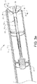
- Fig. 3b shows the diffuser in the folded state.
- the diffuser 11 can have a support member 15 extending in the longitudinal direction in the centre of the air channel 3 of the pipe 2 where the diffuser portion 12 is arranged on the support member 15.
- the diffuser 11 has an inner shaft 16 and an outer shaft 17 which constitute such a support member 15.
- the inner shaft 16 and the outer shaft 17 which are arranged concentrically relative to each other forming a telescopic function are also arranged for shifting between the folded state and the unfolded state of the diffuser 11.
- the diffuser has also pivotable link arms 18.
- the diffuser portion 12 which can be made by fabric for instance is connected to the inner shaft 16 at the centre of the diffuser portion. Further, each link arm 18 has a first end 19 connected to the diffuser portion 12 and a second end 20 pivotally connected to the outer shaft 17. The inner shaft 16 and the outer shaft 17 are displaceable relative to each other and by displacement of the outer shaft 17 relative to the inner shaft 16 the diffuser portion 12 can be folded and unfolded.
- the diffuser portion 12 arranged to cover a part of a cross-section area of the air channel 3 is made by a flexible material such as any suitable fabric which also enables the "umbrella"-function.
- the diffuser portion 12 could be made by a partly air permeable material, though a material impermeable to air often is preferred, or a material which at least will block a major part of the airflow directed to the diffuser portion.
- a material which will block more than 50%, suitably more than 80% and preferably more than 90% of the airflow directed towards the diffuser portion are particularly preferred.
- Fig. 4a shows a further variant of an air vent device 1' for a ventilation system of a vehicle.
- the diffuser portion 12' comprises a hose made from a flexible material, such as a fabric or similar.
- a first end 22 of the hose 12' is attached to an inner shaft 16' and second end 23 of the hose 12' is attached to an outer shaft 17' arranged concentrically around the inner shaft.
- a plurality of link arms 18' is arranged inside the hose 12' between the hose and the inner shaft. These link arms 18' are pivotally connected to the inner shaft 16' and to the outer shaft 17'. Further, each link arm 18' has a pivot joint 24 suitably in the middle of the link arm 18'.
- Fig. 4b shows the diffuser portion 12' in the folded state of the diffuser 11'.
- the diffuser portion 12' can be expanded by movement of the link arms 18' to the unfolded state illustrated in Fig. 4a , and vice versa.
- Fig. 5 shows a further variant of an air vent device 1" for a ventilation system of a vehicle.
- the diffuser portion 12" is inflatable for expanding the diffuser portion.
- the diffuser portion 12" is illustrated both when inflated and not inflated.
- a dashed line 30 indicates the size of the diffuser portion 12" when the diffuser portion is not inflated, whereas the solid line 32 indicates the size of the diffuser portion 12" when the diffuser portion is inflated.
- the flexible material used for the diffuser portion can be a rubber material or similar suitable to be inflated.
- the diffuser portion can be arranged on a tube 31.
- the tube can be connected to an air source and a valve system for providing air to the diffuser portion.
- air can be supplied from the A/C system or HVAC-system used for providing air to the vehicle compartment.
- any other suitable gas could be used for inflating the diffuser portion.
- the diffuser portion could also be displaceable in a longitudinal direction of the pipe for adjustment of the distance between the mouth of the pipe and the diffuser portion while maintaining the size of the diffuser portion.
- Such adjustment of the relative positions of the mouth and the diffuser portion can be also be used for controlling the airflow into the vehicle compartment.
Landscapes
- Physics & Mathematics (AREA)
- Thermal Sciences (AREA)
- Engineering & Computer Science (AREA)
- Mechanical Engineering (AREA)
- Air-Conditioning For Vehicles (AREA)
- Duct Arrangements (AREA)
Abstract
Description
- The invention relates to an air vent device for a ventilation system of a vehicle, which device has a pipe forming an air channel for providing air to a compartment of the vehicle and a diffuser arranged for disturbing the airflow provided to the vehicle compartment.
- In A/C systems or HVAC-systems (Heating, Ventilation and Air Conditioning) for vehicles it is possible to control the flow rate of air into a vehicle compartment. Further, air nozzles for providing the air to the vehicle compartment can be electrically controlled for directing and focusing (or defocusing) the airflow. Focusing or defocusing the airflow by changing the "cone" formed by the flowing air will increase or decrease the airflow rate. This can be performed by an actuator arranged for adjustment of the shape and size of the air nozzle.
- It can however still be a problem with an airflow cooling the skin of a driver or a passenger of a vehicle in an undesired way, particularly in a hot climate when the desired temperature of the air in the vehicle compartment cannot be reached unless the airflow rate from the A/C system is relatively high.
- An objective of the invention is to provide an air intake device for a ventilation system of a vehicle, by which device the air can be provided into a vehicle compartment in a way allowing a relatively high airflow rate at the same time as undesired airflow towards a driver or passenger of the vehicle can be avoided or at least reduced.
- The objective is achieved by an air vent device for a ventilation system of a vehicle, wherein the device has a pipe forming an air channel for providing air to a compartment of the vehicle and a diffuser arranged for disturbing the airflow provided to the vehicle compartment, and wherein the diffuser has a portion made of a flexible material which diffuser portion is arranged to cover a part of a cross-section area of the air channel and the diffuser portion is expandable for varying the size of the covered part of the air channel cross section area.
- The invention is based on the insight that by such an air intake device, at least a large part of the airflow directed towards an occupant can be blocked in order to avoid discomfort for the occupant at the same time as the airflow rate can be relatively high for reaching the desired air temperature in the vehicle compartment.
- The air channel cross-section area covered by the diffuser portion is the area of the air channel overlapping with the diffuser portion when looked at the diffuser portion in a longitudinal direction of the pipe.
- Some examples of "flexible material" for the diffuser portion are different kinds of textile fibre in the form of a fabric for instance, and different kinds of rubber material in the form of a rubber sheet for instance. Such materials are flexible and durable and can adopt different shapes.
- According to one embodiment of the air intake device, the diffuser is foldable between an unfolded state, where said diffuser portion covers a major part of the cross-section area of the air channel, and a folded state, where said diffuser portion covers a minor part of the cross-section area of the air channel. Hereby, the diffuser function and its impact on the airflow can be selected by a driver.
- By "major part" is meant over 50%, preferably over 70% of the total cross-section area of the air channel. By "minor part" is meant less than 20%, preferably less than 10% of the total cross-section area of the air channel.
- The diffuser portion can have the shape of a circular disc in the unfolded state of the diffusor.
- The diffuser portion is preferably arranged to cover a central part of the air channel cross-section area. Hereby, the air flowing past the diffuser portion can be forced to flow along the periphery of the pipe and to leave the nozzle opening in a direction angled outwardly relative to the main airflow direction in the pipe.
- According to a further embodiment of the device, the pipe has a mouth for discharging air into the vehicle compartment and the diffuser portion is arranged at the mouth of the pipe.
- By arranging the diffuser portion at the mouth or nozzle opening, the impact of the diffuser portion on the airflow can be optimized.
- The diffuser can have a support member extending in the longitudinal direction in the centre of the pipe where the diffuser portion is arranged on the support member. Hereby, the diffuser portion can be arranged at the mouth of the pipe without any additional components arranged in the vehicle compartment for this purpose.
- According to a further embodiment of the device, the diffuser portion is displaceable in a longitudinal direction of the pipe for adjustment of the distance between the mouth of the pipe and the diffuser portion while maintaining the size of the diffuser portion. Hereby, the impact of the diffuser can be varied for one and the same diffuser portion size.
- According to another embodiment of the device, the diffuser has pivotable link arms arranged for shifting from the folded state to the unfolded state of the diffuser while expanding the diffuser portion. Hereby, a rational and non-complicated way of expanding the diffuser portion can be achieved, particularly for stretching the diffuser portion when made from a fabric.
- According to a further embodiment of the device, the diffuser has an inner shaft and an outer shaft, wherein the inner shaft and the outer shaft are arranged concentrically relative to each other forming a telescopic function arranged for shifting between the folded state and the unfolded state of the diffuser, and preferably each link arm has a first end connected to the diffuser portion and a second end pivotally connected to the inner shaft or the outer shaft. Hereby, the diffuser function can be easily operated, for example by a motor displacing the inner shaft and the outer shaft relative to each other.
- According to a further embodiment of the device, the diffuser portion is inflatable for expanding the diffuser portion. Hereby, a design with few mechanical components can be achieved, and components already included in the A/C system, such as a fan, can be used for expanding the diffuser portion.
- According to a further embodiment of the device, the diffuser portion has a circular shape in the unfolded state. Hereby, a relatively non-complicated design can be used for making the diffuser portion expandable for varying the size thereof.
- According to a further embodiment of the device, the diffuser portion has a parabolic shape in the unfolded state. Hereby, a robust diffuser portion that can withstand a relatively high airflow can be achieved.
- According to a further embodiment of the device, a concave surface of the diffuser portion is faced against a main air flow direction of the air channel. Hereby, the airflow can be disturbed for creating turbulence which will promote mixing of the air.
- Further advantages and advantageous features of the invention are disclosed in the following description and the claims.
- With reference to the appended drawings, below follows a more detailed description of embodiments of the invention cited as examples.
- In the drawings:
-
Fig. 1 is a schematic view of an air vent device for a ventilation system of a vehicle, -
Fig. 2a is an enlarged view showing a diffuser of the air vent device in an unfolded state, -
Fig. 2b shows the diffuser inFig. 2a in a folded state, -
Fig. 2c is a view taken along C-C inFig. 2a , -
Fig. 2d is a view taken along D-D inFig. 2b , -
Fig. 3a is a partly cut perspective view showing an example embodiment of an air vent device with a diffuser in an unfolded state, -
Fig. 3b shows the air vent device inFig. 3a where the diffuser is folded, -
Fig. 4a is further variant of an air vent device with a diffuser in an unfolded state, -
Fig. 4b shows the air vent device illustrated inFig. 4a where the diffuser is folded, and -
Fig. 5 is a further variant of an air vent device with an inflatable diffuser portion. -
Fig. 1 shows a schematic view of anair vent device 1 for a ventilation system of a vehicle. Thedevice 1 has apipe 2 forming anair channel 3 for providing air to acompartment 4 of the vehicle. Afirst end 5 of thepipe 2 has amouth 6 for discharging air into thecompartment 4. Themouth 6 can be formed by anysuitable nozzle 7 arranged at thefirst end 5 of thepipe 2 or just the pipe end. Asecond end 8 of thepipe 2 is connected to anair source 9 such as an A/C system or HVAC-system comprising a fan blowing air to thevehicle compartment 4. The main direction of the air flow in theair channel 3 is from left to right as indicated by anarrow 10. -
Fig. 2a shows an enlarged view of theair vent device 1, where adiffuser 11 of the air vent device is in an unfolded state. Theair vent device 1 comprises thediffuser 11 for disturbing the airflow provided to thevehicle compartment 4. Thediffuser 11 is suitably arranged at themouth 6 of thepipe 2. Thediffuser 11 has aportion 12 made of a flexible material whichdiffuser portion 12 is arranged to cover a part of a cross-section area of theair channel 3 and thereby blocking air flowing in themain flow direction 10. Thediffuser portion 12 is expandable for varying the size of the covered part of the air channel cross-section area. - The
diffuser 11 can be foldable between an unfolded state, where saiddiffuser portion 12 covers a major part of the cross-section area of theair channel 3, and a folded state, where saiddiffuser portion 12 covers a minor part of the cross-section area of theair channel 3. In the unfolded state the diffuser portion is suitably disc-shaped. The diffuser portion can have a circular shape in the unfolded state. In the example embodiment illustrated inFig. 2a , the diffuser portion has a parabolic shape and aconcave surface 13 of thediffuser portion 12 is faced against the mainair flow direction 10 in theair channel 3 of thepipe 2. - The
diffuser portion 12 is preferably arranged to cover a central part of the air channel cross-section area, thereby blocking the airflow in the centre of theair channel 3. Thediffuser portion 12 is suitably arranged at themouth 6 of thepipe 2. In other words; thediffuser portion 12 is arranged close to themouth 6 of thepipe 2, for example in themouth 6 or just outside themouth 6, preferably on thevehicle compartment 4 side, as illustrated. As further illustrated inFig. 2a , air flowing past thediffuser portion 12 will be forced to leave thepipe 2 at themouth 6 in adirection 14 different from themain flow direction 10. Theairflow direction 14 at themouth 6 is outwardly angled relative to themain flow direction 10. -
Fig. 2b shows an enlarged view of theair vent device 1, where thediffuser 11 of the air vent device is in a folded state. -
Fig. 2c and Fig. 2d show views taken along C-C and D-D inFig. 2a and 2b , respectively. - In
Figs. 2c and 2d , the area covered by thediffuser portion 12 in the unfolded state of the diffuser and the area covered by thediffuser portion 12 in the folded state of the diffuser are illustrated. InFig. 2c , the diffuser portion covers a major part of the air channel cross-section area at the mouth of the pipe, whereas inFig. 2d thediffuser portion 12 covers a minor part of the air channel cross-section area at the mouth. -
Figs. 3a and3b are partly cut perspective views showing an example embodiment of an air vent device. The expandable diffuser can be realized by means of an "umbrella"-function.Figs. 3a and3b show an example embodiment of an air vent device where such an umbrella function is used for achieving the unfolded state and the folded state of the diffuser.Fig. 3a shows the diffuser in the unfolded state andFig. 3b shows the diffuser in the folded state. - The
diffuser 11 can have asupport member 15 extending in the longitudinal direction in the centre of theair channel 3 of thepipe 2 where thediffuser portion 12 is arranged on thesupport member 15. In the example embodiment illustrated inFigs. 3a and3b , thediffuser 11 has aninner shaft 16 and anouter shaft 17 which constitute such asupport member 15. Theinner shaft 16 and theouter shaft 17 which are arranged concentrically relative to each other forming a telescopic function are also arranged for shifting between the folded state and the unfolded state of thediffuser 11. For shifting from the folded state to the unfolded state of thediffuser 11 while expanding thediffuser portion 12, the diffuser has alsopivotable link arms 18. Thediffuser portion 12 which can be made by fabric for instance is connected to theinner shaft 16 at the centre of the diffuser portion. Further, eachlink arm 18 has afirst end 19 connected to thediffuser portion 12 and asecond end 20 pivotally connected to theouter shaft 17. Theinner shaft 16 and theouter shaft 17 are displaceable relative to each other and by displacement of theouter shaft 17 relative to theinner shaft 16 thediffuser portion 12 can be folded and unfolded. - Starting from the unfolded state illustrated in
Fig. 3a , displacement of theouter shaft 17 in a direction from right to left will cause thediffuser portion 12 to be folded and starting from the folded state illustrated inFig. 3b , displacement of theouter shaft 17 in the direction from left to right will cause thediffuser portion 12 to expand to the unfolded state. The relative motion of theinner shaft 16 and theouter shaft 17 can be performed by anelectric motor 21 connected to theouter shaft 17 through a threaded joint, such as a ball screw. - The
diffuser portion 12 arranged to cover a part of a cross-section area of theair channel 3 is made by a flexible material such as any suitable fabric which also enables the "umbrella"-function. - It should be stressed that the
diffuser portion 12 could be made by a partly air permeable material, though a material impermeable to air often is preferred, or a material which at least will block a major part of the airflow directed to the diffuser portion. For example, a material which will block more than 50%, suitably more than 80% and preferably more than 90% of the airflow directed towards the diffuser portion. -
Fig. 4a shows a further variant of an air vent device 1' for a ventilation system of a vehicle. The diffuser portion 12' comprises a hose made from a flexible material, such as a fabric or similar. Afirst end 22 of the hose 12' is attached to an inner shaft 16' andsecond end 23 of the hose 12' is attached to an outer shaft 17' arranged concentrically around the inner shaft. A plurality of link arms 18' is arranged inside the hose 12' between the hose and the inner shaft. These link arms 18' are pivotally connected to the inner shaft 16' and to the outer shaft 17'. Further, each link arm 18' has a pivot joint 24 suitably in the middle of the link arm 18'. -
Fig. 4b shows the diffuser portion 12' in the folded state of the diffuser 11'. By displacement of the inner shaft 16' and the outer shaft 17' relative to each other, the diffuser portion 12' can be expanded by movement of the link arms 18' to the unfolded state illustrated inFig. 4a , and vice versa. -
Fig. 5 shows a further variant of anair vent device 1" for a ventilation system of a vehicle. Thediffuser portion 12" is inflatable for expanding the diffuser portion. Thediffuser portion 12" is illustrated both when inflated and not inflated. A dashedline 30 indicates the size of thediffuser portion 12" when the diffuser portion is not inflated, whereas thesolid line 32 indicates the size of thediffuser portion 12" when the diffuser portion is inflated. The flexible material used for the diffuser portion can be a rubber material or similar suitable to be inflated. The diffuser portion can be arranged on atube 31. The tube can be connected to an air source and a valve system for providing air to the diffuser portion. For example, air can be supplied from the A/C system or HVAC-system used for providing air to the vehicle compartment. Optionally, any other suitable gas could be used for inflating the diffuser portion. - In all example embodiments described herein, in addition to the expandable function, the diffuser portion could also be displaceable in a longitudinal direction of the pipe for adjustment of the distance between the mouth of the pipe and the diffuser portion while maintaining the size of the diffuser portion. Such adjustment of the relative positions of the mouth and the diffuser portion can be also be used for controlling the airflow into the vehicle compartment.
- It is to be understood that the present invention is not limited to the embodiments described above and illustrated in the drawings; rather, the skilled person will recognize that many changes and modifications may be made within the scope of the appended claims.
Claims (15)
- An air vent device (1) for a ventilation system of a vehicle, the device having a pipe (2) forming an air channel (3) for providing air to a compartment (4) of the vehicle and a diffuser (11) for disturbing the airflow provided to the vehicle compartment, characterized in that the diffuser (11) has a portion (12) made of a flexible material which diffuser portion (12) is arranged to cover a part of a cross-section area of the air channel (3) and the diffuser portion is expandable for varying the size of the covered part of the air channel cross section area.
- A device according to claim 1, characterized in that the diffuser (12) is foldable between an unfolded state, where said diffuser portion covers a major part of the cross-section area of the air channel (3) and a folded state, where said diffuser portion covers a minor part of the cross-section area of the air channel (3).
- A device according to claim 2, characterized in that said diffuser portion (12) is disc-shaped in the unfolded state of the diffusor (11).
- A device according to claims 2 or 3, characterized in that the diffuser (11) has pivotable link arms (18) arranged for shifting from the folded state to the unfolded state of the diffuser while expanding the diffuser portion (12).
- A device according to any of claims 2-4, characterized in that the diffuser (11) has an inner shaft (16) and an outer shaft (17), the inner shaft and the outer shaft being arranged concentrically relative to each other forming a telescopic function arranged for shifting between the folded state and the unfolded state of the diffuser (11).
- A device according to claim 4 and 5, characterized in that each link arm (18) has a first end (19) connected to the diffuser portion (12) and a second end (20) connected to the inner shaft (16) or the outer shaft (17).
- A device according to any preceding claim, characterized in that the diffuser portion (12) is made of textile fibres.
- A device according to claim 7, characterized in that the diffuser portion (12) is made of a fabric.
- A device according to any of claims 1-6, characterized in that the diffuser portion (12) is made of rubber material.
- A device according to claim 9, characterized in that the diffuser portion (12) is made of a rubber sheet.
- A device according to any preceding claim, characterized in that the diffuser portion (12) is arranged to cover a central part of the air channel cross-section area.
- A device according to any preceding claim, characterized in that the diffuser (11) has a support member (15) extending in the longitudinal direction in the centre of the pipe (2) and the diffuser portion (12) is arranged on the support member.
- A device according to any preceding claims, characterized in that the pipe (2) has a mouth (6) for discharging air into the vehicle compartment (4) and the diffuser portion (12) is arranged at the mouth of the pipe.
- A device according to claim 13, characterized in that the diffuser portion is displaceable for adjustment of the distance between the diffuser portion and the mouth of the pipe while maintaining the air channel cross-section area covered by the diffuser portion.
- A device according to any preceding claim, characterized in that the diffuser portion (12") is inflatable for expanding the diffuser portion.
Priority Applications (5)
| Application Number | Priority Date | Filing Date | Title |
|---|---|---|---|
| EP19156081.2A EP3693198B1 (en) | 2019-02-07 | 2019-02-07 | An air vent device for a ventilation system of a vehicle |
| EP21157465.2A EP3838638A1 (en) | 2019-02-07 | 2019-02-07 | An air vent device for a ventilation system of a vehicle |
| CN202080009415.9A CN113302068B (en) | 2019-02-07 | 2020-02-04 | Ventilation devices for vehicle ventilation systems |
| PCT/CN2020/074273 WO2020160701A1 (en) | 2019-02-07 | 2020-02-04 | Air vent device for a ventilation system of a vehicle |
| US17/384,296 US12251990B2 (en) | 2019-02-07 | 2021-07-23 | Air vent device for a ventilation system of a vehicle |
Applications Claiming Priority (1)
| Application Number | Priority Date | Filing Date | Title |
|---|---|---|---|
| EP19156081.2A EP3693198B1 (en) | 2019-02-07 | 2019-02-07 | An air vent device for a ventilation system of a vehicle |
Related Child Applications (2)
| Application Number | Title | Priority Date | Filing Date |
|---|---|---|---|
| EP21157465.2A Division-Into EP3838638A1 (en) | 2019-02-07 | 2019-02-07 | An air vent device for a ventilation system of a vehicle |
| EP21157465.2A Division EP3838638A1 (en) | 2019-02-07 | 2019-02-07 | An air vent device for a ventilation system of a vehicle |
Publications (2)
| Publication Number | Publication Date |
|---|---|
| EP3693198A1 true EP3693198A1 (en) | 2020-08-12 |
| EP3693198B1 EP3693198B1 (en) | 2021-05-19 |
Family
ID=65365797
Family Applications (2)
| Application Number | Title | Priority Date | Filing Date |
|---|---|---|---|
| EP19156081.2A Active EP3693198B1 (en) | 2019-02-07 | 2019-02-07 | An air vent device for a ventilation system of a vehicle |
| EP21157465.2A Withdrawn EP3838638A1 (en) | 2019-02-07 | 2019-02-07 | An air vent device for a ventilation system of a vehicle |
Family Applications After (1)
| Application Number | Title | Priority Date | Filing Date |
|---|---|---|---|
| EP21157465.2A Withdrawn EP3838638A1 (en) | 2019-02-07 | 2019-02-07 | An air vent device for a ventilation system of a vehicle |
Country Status (4)
| Country | Link |
|---|---|
| US (1) | US12251990B2 (en) |
| EP (2) | EP3693198B1 (en) |
| CN (1) | CN113302068B (en) |
| WO (1) | WO2020160701A1 (en) |
Cited By (1)
| Publication number | Priority date | Publication date | Assignee | Title |
|---|---|---|---|---|
| US20210245580A1 (en) * | 2020-02-06 | 2021-08-12 | Bruno Dinant | Air vent |
Families Citing this family (5)
| Publication number | Priority date | Publication date | Assignee | Title |
|---|---|---|---|---|
| KR20220057695A (en) * | 2020-10-30 | 2022-05-09 | 현대자동차주식회사 | Apparatus for Roof Vent |
| CN115122877B (en) * | 2022-08-31 | 2022-12-02 | 宁波均胜群英汽车系统股份有限公司 | Air outlet with switchable air outlet direction |
| FR3162165A1 (en) * | 2024-05-16 | 2025-11-21 | Stellantis Auto Sas | VEHICLE AIR VENTILATOR WITH OPTIMIZED COANDA EFFECT IN NEUTRAL DIRECTION AND VEHICLE EQUIPPED WITH SUCH AN AIR VENTILATOR |
| FR3162166A1 (en) * | 2024-05-17 | 2025-11-21 | Stellantis Auto Sas | VEHICLE VENTILATOR WITH COANDA EFFECT AND VEHICLE EQUIPPED WITH SUCH A VENTILATOR |
| EP4653212A1 (en) * | 2024-05-20 | 2025-11-26 | Marelli Automotive Systems Europe plc. | Air vent assembly |
Citations (3)
| Publication number | Priority date | Publication date | Assignee | Title |
|---|---|---|---|---|
| DE102007038212A1 (en) * | 2007-08-14 | 2009-02-19 | Ford Global Technologies, LLC, Dearborn | Ventilating nozzle for use in air-conditioning system in vehicle, for ventilating inner area of vehicle, has air passage housing whose cross section is variably adjustable in comparison to cross section of air supply line |
| WO2016038620A1 (en) * | 2014-09-12 | 2016-03-17 | Faurecia Interior Systems India Pvt. Ltd. | Air vent device comprising a flexible membrane for shutting the air vent device |
| JP2017030684A (en) * | 2015-08-05 | 2017-02-09 | トヨタ自動車株式会社 | Air conditioning register for ceiling |
Family Cites Families (12)
| Publication number | Priority date | Publication date | Assignee | Title |
|---|---|---|---|---|
| GB2156067A (en) * | 1984-03-21 | 1985-10-02 | Austin Rover Group | A closable air vent |
| DE10219696B4 (en) * | 2002-05-02 | 2007-10-11 | Daimlerchrysler Ag | air outlet nozzle |
| DE102009038260A1 (en) * | 2009-08-20 | 2011-02-24 | Fischer Automotive Systems Gmbh & Co. Kg | demister |
| US9500092B2 (en) * | 2013-04-04 | 2016-11-22 | Ford Global Technologies, Llc | Air duct assembly having a flexible vane |
| DE102016001902B3 (en) * | 2016-02-18 | 2017-03-30 | Audi Ag | Device for adjusting an air flow and ventilation device for a vehicle |
| KR101863212B1 (en) * | 2016-10-12 | 2018-06-29 | 서대완 | Damper for duct |
| US20180319253A1 (en) * | 2017-05-02 | 2018-11-08 | GM Global Technology Operations LLC | Vehicle vent assembly with noise damping flap |
| DE102017006124B4 (en) * | 2017-06-28 | 2021-09-09 | Audi Ag | Air vents for a vehicle and instrument panel for a vehicle |
| CN207094934U (en) * | 2017-08-10 | 2018-03-13 | 中国汽车工业工程有限公司 | A kind of square regulating valve of trench air draft |
| DE102018201797A1 (en) * | 2018-02-06 | 2019-08-08 | Bayerische Motoren Werke Aktiengesellschaft | Luftausströmeinheit |
| CN109210748B (en) * | 2018-03-15 | 2025-02-18 | 佛山市润千宇知识产权服务有限公司 | A folding fan structure vent device |
| DE102019000031A1 (en) * | 2019-01-02 | 2020-01-23 | Daimler Ag | Air vents for a vehicle |
-
2019
- 2019-02-07 EP EP19156081.2A patent/EP3693198B1/en active Active
- 2019-02-07 EP EP21157465.2A patent/EP3838638A1/en not_active Withdrawn
-
2020
- 2020-02-04 WO PCT/CN2020/074273 patent/WO2020160701A1/en not_active Ceased
- 2020-02-04 CN CN202080009415.9A patent/CN113302068B/en active Active
-
2021
- 2021-07-23 US US17/384,296 patent/US12251990B2/en active Active
Patent Citations (3)
| Publication number | Priority date | Publication date | Assignee | Title |
|---|---|---|---|---|
| DE102007038212A1 (en) * | 2007-08-14 | 2009-02-19 | Ford Global Technologies, LLC, Dearborn | Ventilating nozzle for use in air-conditioning system in vehicle, for ventilating inner area of vehicle, has air passage housing whose cross section is variably adjustable in comparison to cross section of air supply line |
| WO2016038620A1 (en) * | 2014-09-12 | 2016-03-17 | Faurecia Interior Systems India Pvt. Ltd. | Air vent device comprising a flexible membrane for shutting the air vent device |
| JP2017030684A (en) * | 2015-08-05 | 2017-02-09 | トヨタ自動車株式会社 | Air conditioning register for ceiling |
Cited By (2)
| Publication number | Priority date | Publication date | Assignee | Title |
|---|---|---|---|---|
| US20210245580A1 (en) * | 2020-02-06 | 2021-08-12 | Bruno Dinant | Air vent |
| US11712947B2 (en) * | 2020-02-06 | 2023-08-01 | Faurecia Innenraum Systeme Gmbh | Air vent |
Also Published As
| Publication number | Publication date |
|---|---|
| EP3693198B1 (en) | 2021-05-19 |
| WO2020160701A1 (en) | 2020-08-13 |
| CN113302068A (en) | 2021-08-24 |
| US20210347231A1 (en) | 2021-11-11 |
| CN113302068B (en) | 2023-10-13 |
| US12251990B2 (en) | 2025-03-18 |
| EP3838638A1 (en) | 2021-06-23 |
Similar Documents
| Publication | Publication Date | Title |
|---|---|---|
| US12251990B2 (en) | Air vent device for a ventilation system of a vehicle | |
| US11680581B2 (en) | Nozzle for a fan assembly | |
| US10173561B2 (en) | Seat device operatively connected to HVAC apparatus | |
| CN101622144B (en) | Air outlet with swirl and regular airflow | |
| US9403460B2 (en) | Vehicle seating assembly having a climate controlled seat utilizing a plenum volume and flexible hoses | |
| US6805624B2 (en) | Air outlet nozzle and method of making and using same | |
| CN102725158B (en) | Enhanced air discharging nozzle | |
| JP2007517720A (en) | Vehicle seat | |
| US10457120B2 (en) | Air outlet for arrangement in the passenger compartment of a motor vehicle | |
| EP0703105A1 (en) | Air outlet register for an opening in a vehicle | |
| US12296653B2 (en) | Air vent and vehicle with an air vent | |
| JP6318931B2 (en) | Air blowing device | |
| US6439296B1 (en) | Heating or air-conditioning system for a vehicle occupant compartment | |
| US8512111B2 (en) | Vehicle cowl box structure | |
| US20170326941A1 (en) | Air vent for arrangement in the interior of a motor vehicle | |
| US4163415A (en) | Ventilation device | |
| CN106163845B (en) | Ventilation device comprising a guide element axially movable relative to the housing | |
| JP2019166910A (en) | Seat air conditioner | |
| CN106103156B (en) | Ventilation unit with conducting element that can be movable on guide rail | |
| JPH0687325A (en) | Control device for fluid flow blowout | |
| US11364774B2 (en) | Wind direction adjustment device | |
| JP2002138513A (en) | Cool and warm air blaster for construction machine | |
| JP2007218511A (en) | Air conditioner | |
| EP3191330B1 (en) | Air vent device comprising a flexible membrane for shutting the air vent device | |
| JP7834268B2 (en) | Sun visor |
Legal Events
| Date | Code | Title | Description |
|---|---|---|---|
| PUAI | Public reference made under article 153(3) epc to a published international application that has entered the european phase |
Free format text: ORIGINAL CODE: 0009012 |
|
| STAA | Information on the status of an ep patent application or granted ep patent |
Free format text: STATUS: REQUEST FOR EXAMINATION WAS MADE |
|
| 17P | Request for examination filed |
Effective date: 20190207 |
|
| AK | Designated contracting states |
Kind code of ref document: A1 Designated state(s): AL AT BE BG CH CY CZ DE DK EE ES FI FR GB GR HR HU IE IS IT LI LT LU LV MC MK MT NL NO PL PT RO RS SE SI SK SM TR |
|
| AX | Request for extension of the european patent |
Extension state: BA ME |
|
| GRAP | Despatch of communication of intention to grant a patent |
Free format text: ORIGINAL CODE: EPIDOSNIGR1 |
|
| STAA | Information on the status of an ep patent application or granted ep patent |
Free format text: STATUS: GRANT OF PATENT IS INTENDED |
|
| RIC1 | Information provided on ipc code assigned before grant |
Ipc: F24F 13/14 20060101ALN20210225BHEP Ipc: B60H 1/34 20060101AFI20210225BHEP |
|
| GRAS | Grant fee paid |
Free format text: ORIGINAL CODE: EPIDOSNIGR3 |
|
| GRAA | (expected) grant |
Free format text: ORIGINAL CODE: 0009210 |
|
| STAA | Information on the status of an ep patent application or granted ep patent |
Free format text: STATUS: THE PATENT HAS BEEN GRANTED |
|
| INTG | Intention to grant announced |
Effective date: 20210323 |
|
| RIN1 | Information on inventor provided before grant (corrected) |
Inventor name: PIHLSGARD, MANS Inventor name: SETTERBERG, JOHAN |
|
| AK | Designated contracting states |
Kind code of ref document: B1 Designated state(s): AL AT BE BG CH CY CZ DE DK EE ES FI FR GB GR HR HU IE IS IT LI LT LU LV MC MK MT NL NO PL PT RO RS SE SI SK SM TR |
|
| REG | Reference to a national code |
Ref country code: GB Ref legal event code: FG4D |
|
| REG | Reference to a national code |
Ref country code: CH Ref legal event code: EP |
|
| REG | Reference to a national code |
Ref country code: DE Ref legal event code: R096 Ref document number: 602019004617 Country of ref document: DE |
|
| REG | Reference to a national code |
Ref country code: AT Ref legal event code: REF Ref document number: 1393647 Country of ref document: AT Kind code of ref document: T Effective date: 20210615 |
|
| REG | Reference to a national code |
Ref country code: IE Ref legal event code: FG4D |
|
| REG | Reference to a national code |
Ref country code: LT Ref legal event code: MG9D |
|
| REG | Reference to a national code |
Ref country code: AT Ref legal event code: MK05 Ref document number: 1393647 Country of ref document: AT Kind code of ref document: T Effective date: 20210519 |
|
| REG | Reference to a national code |
Ref country code: NL Ref legal event code: MP Effective date: 20210519 |
|
| PG25 | Lapsed in a contracting state [announced via postgrant information from national office to epo] |
Ref country code: BG Free format text: LAPSE BECAUSE OF FAILURE TO SUBMIT A TRANSLATION OF THE DESCRIPTION OR TO PAY THE FEE WITHIN THE PRESCRIBED TIME-LIMIT Effective date: 20210819 Ref country code: AT Free format text: LAPSE BECAUSE OF FAILURE TO SUBMIT A TRANSLATION OF THE DESCRIPTION OR TO PAY THE FEE WITHIN THE PRESCRIBED TIME-LIMIT Effective date: 20210519 Ref country code: LT Free format text: LAPSE BECAUSE OF FAILURE TO SUBMIT A TRANSLATION OF THE DESCRIPTION OR TO PAY THE FEE WITHIN THE PRESCRIBED TIME-LIMIT Effective date: 20210519 Ref country code: HR Free format text: LAPSE BECAUSE OF FAILURE TO SUBMIT A TRANSLATION OF THE DESCRIPTION OR TO PAY THE FEE WITHIN THE PRESCRIBED TIME-LIMIT Effective date: 20210519 Ref country code: FI Free format text: LAPSE BECAUSE OF FAILURE TO SUBMIT A TRANSLATION OF THE DESCRIPTION OR TO PAY THE FEE WITHIN THE PRESCRIBED TIME-LIMIT Effective date: 20210519 |
|
| PG25 | Lapsed in a contracting state [announced via postgrant information from national office to epo] |
Ref country code: IS Free format text: LAPSE BECAUSE OF FAILURE TO SUBMIT A TRANSLATION OF THE DESCRIPTION OR TO PAY THE FEE WITHIN THE PRESCRIBED TIME-LIMIT Effective date: 20210919 Ref country code: LV Free format text: LAPSE BECAUSE OF FAILURE TO SUBMIT A TRANSLATION OF THE DESCRIPTION OR TO PAY THE FEE WITHIN THE PRESCRIBED TIME-LIMIT Effective date: 20210519 Ref country code: NO Free format text: LAPSE BECAUSE OF FAILURE TO SUBMIT A TRANSLATION OF THE DESCRIPTION OR TO PAY THE FEE WITHIN THE PRESCRIBED TIME-LIMIT Effective date: 20210819 Ref country code: PL Free format text: LAPSE BECAUSE OF FAILURE TO SUBMIT A TRANSLATION OF THE DESCRIPTION OR TO PAY THE FEE WITHIN THE PRESCRIBED TIME-LIMIT Effective date: 20210519 Ref country code: RS Free format text: LAPSE BECAUSE OF FAILURE TO SUBMIT A TRANSLATION OF THE DESCRIPTION OR TO PAY THE FEE WITHIN THE PRESCRIBED TIME-LIMIT Effective date: 20210519 Ref country code: PT Free format text: LAPSE BECAUSE OF FAILURE TO SUBMIT A TRANSLATION OF THE DESCRIPTION OR TO PAY THE FEE WITHIN THE PRESCRIBED TIME-LIMIT Effective date: 20210920 Ref country code: SE Free format text: LAPSE BECAUSE OF FAILURE TO SUBMIT A TRANSLATION OF THE DESCRIPTION OR TO PAY THE FEE WITHIN THE PRESCRIBED TIME-LIMIT Effective date: 20210519 |
|
| PG25 | Lapsed in a contracting state [announced via postgrant information from national office to epo] |
Ref country code: NL Free format text: LAPSE BECAUSE OF FAILURE TO SUBMIT A TRANSLATION OF THE DESCRIPTION OR TO PAY THE FEE WITHIN THE PRESCRIBED TIME-LIMIT Effective date: 20210519 |
|
| PG25 | Lapsed in a contracting state [announced via postgrant information from national office to epo] |
Ref country code: DK Free format text: LAPSE BECAUSE OF FAILURE TO SUBMIT A TRANSLATION OF THE DESCRIPTION OR TO PAY THE FEE WITHIN THE PRESCRIBED TIME-LIMIT Effective date: 20210519 Ref country code: CZ Free format text: LAPSE BECAUSE OF FAILURE TO SUBMIT A TRANSLATION OF THE DESCRIPTION OR TO PAY THE FEE WITHIN THE PRESCRIBED TIME-LIMIT Effective date: 20210519 Ref country code: RO Free format text: LAPSE BECAUSE OF FAILURE TO SUBMIT A TRANSLATION OF THE DESCRIPTION OR TO PAY THE FEE WITHIN THE PRESCRIBED TIME-LIMIT Effective date: 20210519 Ref country code: SM Free format text: LAPSE BECAUSE OF FAILURE TO SUBMIT A TRANSLATION OF THE DESCRIPTION OR TO PAY THE FEE WITHIN THE PRESCRIBED TIME-LIMIT Effective date: 20210519 Ref country code: SK Free format text: LAPSE BECAUSE OF FAILURE TO SUBMIT A TRANSLATION OF THE DESCRIPTION OR TO PAY THE FEE WITHIN THE PRESCRIBED TIME-LIMIT Effective date: 20210519 Ref country code: ES Free format text: LAPSE BECAUSE OF FAILURE TO SUBMIT A TRANSLATION OF THE DESCRIPTION OR TO PAY THE FEE WITHIN THE PRESCRIBED TIME-LIMIT Effective date: 20210519 Ref country code: EE Free format text: LAPSE BECAUSE OF FAILURE TO SUBMIT A TRANSLATION OF THE DESCRIPTION OR TO PAY THE FEE WITHIN THE PRESCRIBED TIME-LIMIT Effective date: 20210519 |
|
| REG | Reference to a national code |
Ref country code: DE Ref legal event code: R097 Ref document number: 602019004617 Country of ref document: DE |
|
| PLBE | No opposition filed within time limit |
Free format text: ORIGINAL CODE: 0009261 |
|
| STAA | Information on the status of an ep patent application or granted ep patent |
Free format text: STATUS: NO OPPOSITION FILED WITHIN TIME LIMIT |
|
| 26N | No opposition filed |
Effective date: 20220222 |
|
| PG25 | Lapsed in a contracting state [announced via postgrant information from national office to epo] |
Ref country code: IS Free format text: LAPSE BECAUSE OF FAILURE TO SUBMIT A TRANSLATION OF THE DESCRIPTION OR TO PAY THE FEE WITHIN THE PRESCRIBED TIME-LIMIT Effective date: 20210919 Ref country code: AL Free format text: LAPSE BECAUSE OF FAILURE TO SUBMIT A TRANSLATION OF THE DESCRIPTION OR TO PAY THE FEE WITHIN THE PRESCRIBED TIME-LIMIT Effective date: 20210519 |
|
| PG25 | Lapsed in a contracting state [announced via postgrant information from national office to epo] |
Ref country code: IT Free format text: LAPSE BECAUSE OF FAILURE TO SUBMIT A TRANSLATION OF THE DESCRIPTION OR TO PAY THE FEE WITHIN THE PRESCRIBED TIME-LIMIT Effective date: 20210519 |
|
| PG25 | Lapsed in a contracting state [announced via postgrant information from national office to epo] |
Ref country code: MC Free format text: LAPSE BECAUSE OF FAILURE TO SUBMIT A TRANSLATION OF THE DESCRIPTION OR TO PAY THE FEE WITHIN THE PRESCRIBED TIME-LIMIT Effective date: 20210519 |
|
| REG | Reference to a national code |
Ref country code: CH Ref legal event code: PL |
|
| REG | Reference to a national code |
Ref country code: BE Ref legal event code: MM Effective date: 20220228 |
|
| PG25 | Lapsed in a contracting state [announced via postgrant information from national office to epo] |
Ref country code: LU Free format text: LAPSE BECAUSE OF NON-PAYMENT OF DUE FEES Effective date: 20220207 |
|
| PG25 | Lapsed in a contracting state [announced via postgrant information from national office to epo] |
Ref country code: LI Free format text: LAPSE BECAUSE OF NON-PAYMENT OF DUE FEES Effective date: 20220228 Ref country code: IE Free format text: LAPSE BECAUSE OF NON-PAYMENT OF DUE FEES Effective date: 20220207 Ref country code: CH Free format text: LAPSE BECAUSE OF NON-PAYMENT OF DUE FEES Effective date: 20220228 |
|
| PG25 | Lapsed in a contracting state [announced via postgrant information from national office to epo] |
Ref country code: BE Free format text: LAPSE BECAUSE OF NON-PAYMENT OF DUE FEES Effective date: 20220228 |
|
| PG25 | Lapsed in a contracting state [announced via postgrant information from national office to epo] |
Ref country code: MK Free format text: LAPSE BECAUSE OF FAILURE TO SUBMIT A TRANSLATION OF THE DESCRIPTION OR TO PAY THE FEE WITHIN THE PRESCRIBED TIME-LIMIT Effective date: 20210519 Ref country code: CY Free format text: LAPSE BECAUSE OF FAILURE TO SUBMIT A TRANSLATION OF THE DESCRIPTION OR TO PAY THE FEE WITHIN THE PRESCRIBED TIME-LIMIT Effective date: 20210519 |
|
| PG25 | Lapsed in a contracting state [announced via postgrant information from national office to epo] |
Ref country code: HU Free format text: LAPSE BECAUSE OF FAILURE TO SUBMIT A TRANSLATION OF THE DESCRIPTION OR TO PAY THE FEE WITHIN THE PRESCRIBED TIME-LIMIT; INVALID AB INITIO Effective date: 20190207 |
|
| PG25 | Lapsed in a contracting state [announced via postgrant information from national office to epo] |
Ref country code: MT Free format text: LAPSE BECAUSE OF FAILURE TO SUBMIT A TRANSLATION OF THE DESCRIPTION OR TO PAY THE FEE WITHIN THE PRESCRIBED TIME-LIMIT Effective date: 20210519 |
|
| PG25 | Lapsed in a contracting state [announced via postgrant information from national office to epo] |
Ref country code: GR Free format text: LAPSE BECAUSE OF NON-PAYMENT OF DUE FEES Effective date: 20210519 |
|
| PG25 | Lapsed in a contracting state [announced via postgrant information from national office to epo] |
Ref country code: GR Free format text: LAPSE BECAUSE OF NON-PAYMENT OF DUE FEES Effective date: 20210519 |
|
| PG25 | Lapsed in a contracting state [announced via postgrant information from national office to epo] |
Ref country code: TR Free format text: LAPSE BECAUSE OF FAILURE TO SUBMIT A TRANSLATION OF THE DESCRIPTION OR TO PAY THE FEE WITHIN THE PRESCRIBED TIME-LIMIT Effective date: 20210519 |
|
| PGFP | Annual fee paid to national office [announced via postgrant information from national office to epo] |
Ref country code: GB Payment date: 20251201 Year of fee payment: 8 |
|
| PGFP | Annual fee paid to national office [announced via postgrant information from national office to epo] |
Ref country code: FR Payment date: 20251201 Year of fee payment: 8 |
|
| PGFP | Annual fee paid to national office [announced via postgrant information from national office to epo] |
Ref country code: DE Payment date: 20260217 Year of fee payment: 8 |