EP3693106A1 - Additive manufacturing cover gas shield - Google Patents
Additive manufacturing cover gas shield Download PDFInfo
- Publication number
- EP3693106A1 EP3693106A1 EP20155678.4A EP20155678A EP3693106A1 EP 3693106 A1 EP3693106 A1 EP 3693106A1 EP 20155678 A EP20155678 A EP 20155678A EP 3693106 A1 EP3693106 A1 EP 3693106A1
- Authority
- EP
- European Patent Office
- Prior art keywords
- gas shield
- recited
- gas
- chamber
- additive manufacturing
- Prior art date
- Legal status (The legal status is an assumption and is not a legal conclusion. Google has not performed a legal analysis and makes no representation as to the accuracy of the status listed.)
- Pending
Links
Images

Classifications
-
- B—PERFORMING OPERATIONS; TRANSPORTING
- B33—ADDITIVE MANUFACTURING TECHNOLOGY
- B33Y—ADDITIVE MANUFACTURING, i.e. MANUFACTURING OF THREE-DIMENSIONAL [3D] OBJECTS BY ADDITIVE DEPOSITION, ADDITIVE AGGLOMERATION OR ADDITIVE LAYERING, e.g. BY 3D PRINTING, STEREOLITHOGRAPHY OR SELECTIVE LASER SINTERING
- B33Y30/00—Apparatus for additive manufacturing; Details thereof or accessories therefor
-
- B—PERFORMING OPERATIONS; TRANSPORTING
- B22—CASTING; POWDER METALLURGY
- B22F—WORKING METALLIC POWDER; MANUFACTURE OF ARTICLES FROM METALLIC POWDER; MAKING METALLIC POWDER; APPARATUS OR DEVICES SPECIALLY ADAPTED FOR METALLIC POWDER
- B22F10/00—Additive manufacturing of workpieces or articles from metallic powder
- B22F10/20—Direct sintering or melting
- B22F10/28—Powder bed fusion, e.g. selective laser melting [SLM] or electron beam melting [EBM]
-
- B—PERFORMING OPERATIONS; TRANSPORTING
- B22—CASTING; POWDER METALLURGY
- B22F—WORKING METALLIC POWDER; MANUFACTURE OF ARTICLES FROM METALLIC POWDER; MAKING METALLIC POWDER; APPARATUS OR DEVICES SPECIALLY ADAPTED FOR METALLIC POWDER
- B22F12/00—Apparatus or devices specially adapted for additive manufacturing; Auxiliary means for additive manufacturing; Combinations of additive manufacturing apparatus or devices with other processing apparatus or devices
- B22F12/70—Gas flow means
-
- B—PERFORMING OPERATIONS; TRANSPORTING
- B29—WORKING OF PLASTICS; WORKING OF SUBSTANCES IN A PLASTIC STATE IN GENERAL
- B29C—SHAPING OR JOINING OF PLASTICS; SHAPING OF MATERIAL IN A PLASTIC STATE, NOT OTHERWISE PROVIDED FOR; AFTER-TREATMENT OF THE SHAPED PRODUCTS, e.g. REPAIRING
- B29C64/00—Additive manufacturing, i.e. manufacturing of three-dimensional [3D] objects by additive deposition, additive agglomeration or additive layering, e.g. by 3D printing, stereolithography or selective laser sintering
- B29C64/10—Processes of additive manufacturing
- B29C64/141—Processes of additive manufacturing using only solid materials
- B29C64/153—Processes of additive manufacturing using only solid materials using layers of powder being selectively joined, e.g. by selective laser sintering or melting
-
- B—PERFORMING OPERATIONS; TRANSPORTING
- B29—WORKING OF PLASTICS; WORKING OF SUBSTANCES IN A PLASTIC STATE IN GENERAL
- B29C—SHAPING OR JOINING OF PLASTICS; SHAPING OF MATERIAL IN A PLASTIC STATE, NOT OTHERWISE PROVIDED FOR; AFTER-TREATMENT OF THE SHAPED PRODUCTS, e.g. REPAIRING
- B29C64/00—Additive manufacturing, i.e. manufacturing of three-dimensional [3D] objects by additive deposition, additive agglomeration or additive layering, e.g. by 3D printing, stereolithography or selective laser sintering
- B29C64/30—Auxiliary operations or equipment
- B29C64/364—Conditioning of environment
-
- B—PERFORMING OPERATIONS; TRANSPORTING
- B22—CASTING; POWDER METALLURGY
- B22F—WORKING METALLIC POWDER; MANUFACTURE OF ARTICLES FROM METALLIC POWDER; MAKING METALLIC POWDER; APPARATUS OR DEVICES SPECIALLY ADAPTED FOR METALLIC POWDER
- B22F10/00—Additive manufacturing of workpieces or articles from metallic powder
- B22F10/30—Process control
- B22F10/32—Process control of the atmosphere, e.g. composition or pressure in a building chamber
- B22F10/322—Process control of the atmosphere, e.g. composition or pressure in a building chamber of the gas flow, e.g. rate or direction
-
- B—PERFORMING OPERATIONS; TRANSPORTING
- B22—CASTING; POWDER METALLURGY
- B22F—WORKING METALLIC POWDER; MANUFACTURE OF ARTICLES FROM METALLIC POWDER; MAKING METALLIC POWDER; APPARATUS OR DEVICES SPECIALLY ADAPTED FOR METALLIC POWDER
- B22F2201/00—Treatment under specific atmosphere
- B22F2201/10—Inert gases
-
- B—PERFORMING OPERATIONS; TRANSPORTING
- B22—CASTING; POWDER METALLURGY
- B22F—WORKING METALLIC POWDER; MANUFACTURE OF ARTICLES FROM METALLIC POWDER; MAKING METALLIC POWDER; APPARATUS OR DEVICES SPECIALLY ADAPTED FOR METALLIC POWDER
- B22F2999/00—Aspects linked to processes or compositions used in powder metallurgy
-
- B—PERFORMING OPERATIONS; TRANSPORTING
- B33—ADDITIVE MANUFACTURING TECHNOLOGY
- B33Y—ADDITIVE MANUFACTURING, i.e. MANUFACTURING OF THREE-DIMENSIONAL [3D] OBJECTS BY ADDITIVE DEPOSITION, ADDITIVE AGGLOMERATION OR ADDITIVE LAYERING, e.g. BY 3D PRINTING, STEREOLITHOGRAPHY OR SELECTIVE LASER SINTERING
- B33Y10/00—Processes of additive manufacturing
-
- B—PERFORMING OPERATIONS; TRANSPORTING
- B33—ADDITIVE MANUFACTURING TECHNOLOGY
- B33Y—ADDITIVE MANUFACTURING, i.e. MANUFACTURING OF THREE-DIMENSIONAL [3D] OBJECTS BY ADDITIVE DEPOSITION, ADDITIVE AGGLOMERATION OR ADDITIVE LAYERING, e.g. BY 3D PRINTING, STEREOLITHOGRAPHY OR SELECTIVE LASER SINTERING
- B33Y40/00—Auxiliary operations or equipment, e.g. for material handling
-
- Y—GENERAL TAGGING OF NEW TECHNOLOGICAL DEVELOPMENTS; GENERAL TAGGING OF CROSS-SECTIONAL TECHNOLOGIES SPANNING OVER SEVERAL SECTIONS OF THE IPC; TECHNICAL SUBJECTS COVERED BY FORMER USPC CROSS-REFERENCE ART COLLECTIONS [XRACs] AND DIGESTS
- Y02—TECHNOLOGIES OR APPLICATIONS FOR MITIGATION OR ADAPTATION AGAINST CLIMATE CHANGE
- Y02P—CLIMATE CHANGE MITIGATION TECHNOLOGIES IN THE PRODUCTION OR PROCESSING OF GOODS
- Y02P10/00—Technologies related to metal processing
- Y02P10/25—Process efficiency
Definitions
- the present disclosure relates to additive manufacturing and, more particularly, to a shield for Laser Powder Bed Fusion.
- Laser Powder Bed Fusion is an additive manufacturing technique in which a laser is utilized to sinter powdered material.
- the laser may be guided by a 3D model to bind the powdered material and grow a solid structure component.
- a cover gas is used to evacuate precipitate / condensate from the build process. Excessive condensate / gas flow may distort the component being additively manufactured through thermal dissipation affects. A distorted additively manufactured part may result in a recoater crash.
- a gas shield for an additive manufacturing system includes a bracket and a flexible curtain mounted to the bracket.
- a further aspect of the present disclosure includes a multiple of magnets attached to the bracket.
- a further aspect of the present disclosure includes that the bracket is flexible.
- a further aspect of the present disclosure includes that the flexible curtain is movable.
- a further aspect of the present disclosure includes that the flexible curtain comprises a multiple of slats.
- An additive manufacturing system includes a chamber a powder dispenser adjacent to the chamber and a gas shield to at least partially segregate the powder dispenser and the chamber.
- a further aspect of the present disclosure includes that the gas shield is magnetically attached adjacent to the chamber.
- a further aspect of the present disclosure includes that the gas shield is located adjacent to the build plate.
- a further aspect of the present disclosure includes that the gas shield is flexible.
- a further aspect of the present disclosure includes that the gas shield permits passage of the recoater blade.
- a method of additively manufacturing according to one disclosed non-limiting embodiment of the present disclosure includes removably mounting a gas shield to at least partially segregate a powder dispenser and a chamber.
- a further aspect of the present disclosure includes adjusting the gas shield to be non-linear.
- a further aspect of the present disclosure includes adjusting the gas shield with respect to a gas flow.
- a further aspect of the present disclosure includes permitting a recoater blade to pass under the gas shield.
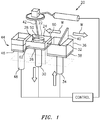
- FIG. 1 schematically illustrates an additive manufacturing system 20 that may have particular applicability to an additive manufacturing process.
- a Laser Powder Bed Fusion system 20 is schematically illustrated it should be appreciated that other additive manufacturing processes that also utilize a recoater blade such as selective laser melting (SLM) will also benefit herefrom.
- SLM selective laser melting
- the additive manufacturing process sequentially builds-up layers of atomized alloy and/or ceramic powder material that include but are not limited to, 625 Alloy, 718 Alloy, 230 Alloy, stainless steel, tool steel, cobalt chrome, titanium, nickel, aluminum and others in atomized powder material form. Alloys such as 625, 718 and 230 may have specific benefit for parts that operate in high temperature environments, such as, for example, environments typically encountered by aerospace and gas turbine engine components.
- the system 20 generally includes a chamber 22 that includes a process space 24 in which a build plate 26 upon which an additively manufactured component 28 is grown. This build plate 26 can be lowered by an actuator 30, so that the component 28 can be produced in the process space 24.
- a stock of powder 32 is located in a powder dispenser 36 atop a dispenser plate 38 that can be raised by an actuator 34.
- the additively manufactured component 28 is grown on the build plate 26 as a recoater blade 40 sweeps across the surface thereof in a linear recoat direction as indicated by arrow W.
- the recoater blade 40 is moved over the stock of powder 32 in the dispenser 36, with the result that, after the lowering of the build plate 26, a further layer of powder is applied and leveled by the recoater blade 40 to form a layer of the component 28 by a laser beam 42.
- the recoater blade 40 then spreads excess powder 32 into a powder collector 44 atop a collector plate 46 that is correspondingly lowered by an actuator 48.
- the additively manufactured component 28 is grown on the build plate 26 and the recoater blade 40 sweeps across the surface thereof in a linear recoat direction as indicated by arrow W.
- the chamber 22 includes a window 50 through which the laser beam 42 is directed.
- An inlet manifold 60 and an outlet manifold 62 communicate an inert process gas 70 such as argon or nitrogen through the process space 24 over the build plate 26.
- This inert process gas sweeps over the surface of the component 28 to minimize undesirable reactions of the melting bath of component material with gaseous constituents to discharge possible evaporation products of the component material through the outlet manifold 62.
- a feed gas may also be provided to facilitate formation of a layer with a composition different from that of the component material.
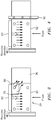
- turbulence in the gas flow from the inlet manifold 60 may result in a no-build zone 80 in the back corner of the build plate 26 adjacent to the inlet manifold 60 and the powder dispenser 36, making it impossible to build certain geometries.
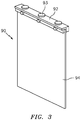
- a gas shield 90 is selectively positioned adjacent to the build plate 26, the inlet manifold 60 and the powder dispenser 36 ( FIG. 4 ).
- the gas shield 90 includes a mounting bracket 92 and a flexible non-outgassing polymer curtain 94.
- the mounting bracket 92 may include attachments 93 (e.g., magnets) which permit the gas shield 90 to be removably attached within the chamber 22.
- the curtain 94 is flexible to permit the recoater blade 40 to pass under during recoat action.
- the gas shield 90 may be automatically moved in response to the movement of the recoater blade 40 during recoat action.
- the gas shield 90 segregates the process space 24 from the powder dispenser 36 to minimize the turbulence in the gas flow from the inlet manifold 60. That is, the gas shield 90 blocks the gas from entering the powder dispenser 36 which causes the turbulence. Clean, laminar gas flow facilitates removal of excessive condensate during the build process.
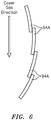
- the curtain 94 may be formed of a multiple of overlapping slats 94A ( FIG. 5 ).
- the overlapping slats 94A may be overlapped with respect to the direction of the flow to facilitate flow to minimize the turbulence in the gas flow from the inlet manifold 60 ( FIG. 6 ).
- the gas shield 90 may include a flexible mounting bracket 92 with a multiple of articulating joints 96 (e.g., chain links), to form a non-linear shield within the process space 24. That is, the curtain 94 forms a non-linear barrier that facilitates concentration and direction of the gas.
- articulating joints 96 e.g., chain links
- the shield segregates and directs the cover gas flow which directly affects build quality.
- the shield also increases the usable area on the build plate and significantly reduces the possibility of a build crash.
Landscapes
- Engineering & Computer Science (AREA)
- Chemical & Material Sciences (AREA)
- Materials Engineering (AREA)
- Manufacturing & Machinery (AREA)
- Physics & Mathematics (AREA)
- Optics & Photonics (AREA)
- Plasma & Fusion (AREA)
- Mechanical Engineering (AREA)
- Health & Medical Sciences (AREA)
- Environmental & Geological Engineering (AREA)
- Toxicology (AREA)
- Powder Metallurgy (AREA)
Abstract
Description
- The present disclosure relates to additive manufacturing and, more particularly, to a shield for Laser Powder Bed Fusion.
- Laser Powder Bed Fusion is an additive manufacturing technique in which a laser is utilized to sinter powdered material. The laser may be guided by a 3D model to bind the powdered material and grow a solid structure component.
- When constructing the component via Laser Powder Bed Fusion, a cover gas is used to evacuate precipitate / condensate from the build process. Excessive condensate / gas flow may distort the component being additively manufactured through thermal dissipation affects. A distorted additively manufactured part may result in a recoater crash.
- A gas shield for an additive manufacturing system according to one disclosed non-limiting embodiment of the present disclosure includes a bracket and a flexible curtain mounted to the bracket.
- A further aspect of the present disclosure includes a multiple of magnets attached to the bracket.
- A further aspect of the present disclosure includes that the bracket is flexible.
- A further aspect of the present disclosure includes that the flexible curtain is movable.
- A further aspect of the present disclosure includes that the flexible curtain comprises a multiple of slats.
- An additive manufacturing system according to one disclosed non-limiting embodiment of the present disclosure includes a chamber a powder dispenser adjacent to the chamber and a gas shield to at least partially segregate the powder dispenser and the chamber.
- A further aspect of the present disclosure includes that the gas shield is magnetically attached adjacent to the chamber.
- A further aspect of the present disclosure includes that the gas shield is located adjacent to the build plate.
- A further aspect of the present disclosure includes that the gas shield is flexible.
- A further aspect of the present disclosure includes that the gas shield permits passage of the recoater blade.
- A method of additively manufacturing according to one disclosed non-limiting embodiment of the present disclosure includes removably mounting a gas shield to at least partially segregate a powder dispenser and a chamber.
- A further aspect of the present disclosure includes adjusting the gas shield to be non-linear.
- A further aspect of the present disclosure includes adjusting the gas shield with respect to a gas flow.
- A further aspect of the present disclosure includes permitting a recoater blade to pass under the gas shield.
- The foregoing features and elements may be combined in various combinations without exclusivity, unless expressly indicated otherwise. These features and elements as well as the operation thereof will become more apparent in light of the following description and the accompanying drawings. It should be understood, however, the following description and drawings are intended to be exemplary in nature and non-limiting.
- Various features will become apparent to those skilled in the art from the following detailed description of the disclosed non-limiting embodiment. The components in the drawings are not necessarily to scale. Moreover, in the drawings, like reference numerals designate corresponding parts throughout the several views. The drawings that accompany the detailed description can be briefly described as follows:
-
FIG. 1 is a schematic cross section of a Laser Powder Bed Fusion system. -
FIG. 2 is a top schematic view of a no-build zone in a back corner of a build plate of the system. -
FIG. 3 is a perspective view of the gas shield according to one disclosed non-limiting embodiment. -
FIG. 4 is a top view of a build plate of the system with a gas shield according to one disclosed non-limiting embodiment. -
FIG. 5 is a perspective view of another gas shield according to one disclosed non-limiting embodiment. -
FIG. 6 is an enlarged view of the gas shield ofFIG. 5 illustrating an arrangement of the gas shield with respect to a gas flow. -
FIG. 1 schematically illustrates anadditive manufacturing system 20 that may have particular applicability to an additive manufacturing process. Although a Laser Powder Bed Fusionsystem 20 is schematically illustrated it should be appreciated that other additive manufacturing processes that also utilize a recoater blade such as selective laser melting (SLM) will also benefit herefrom. The additive manufacturing process sequentially builds-up layers of atomized alloy and/or ceramic powder material that include but are not limited to, 625 Alloy, 718 Alloy, 230 Alloy, stainless steel, tool steel, cobalt chrome, titanium, nickel, aluminum and others in atomized powder material form. Alloys such as 625, 718 and 230 may have specific benefit for parts that operate in high temperature environments, such as, for example, environments typically encountered by aerospace and gas turbine engine components. - The
system 20 generally includes achamber 22 that includes aprocess space 24 in which abuild plate 26 upon which an additively manufacturedcomponent 28 is grown. Thisbuild plate 26 can be lowered by anactuator 30, so that thecomponent 28 can be produced in theprocess space 24. - A stock of
powder 32 is located in apowder dispenser 36 atop adispenser plate 38 that can be raised by anactuator 34. The additively manufacturedcomponent 28 is grown on thebuild plate 26 as arecoater blade 40 sweeps across the surface thereof in a linear recoat direction as indicated by arrow W. Therecoater blade 40 is moved over the stock ofpowder 32 in thedispenser 36, with the result that, after the lowering of thebuild plate 26, a further layer of powder is applied and leveled by therecoater blade 40 to form a layer of thecomponent 28 by alaser beam 42. Therecoater blade 40 then spreadsexcess powder 32 into apowder collector 44 atop acollector plate 46 that is correspondingly lowered by anactuator 48. The additively manufacturedcomponent 28 is grown on thebuild plate 26 and therecoater blade 40 sweeps across the surface thereof in a linear recoat direction as indicated by arrow W. - The
chamber 22 includes awindow 50 through which thelaser beam 42 is directed. Aninlet manifold 60 and anoutlet manifold 62 communicate aninert process gas 70 such as argon or nitrogen through theprocess space 24 over thebuild plate 26. This inert process gas sweeps over the surface of thecomponent 28 to minimize undesirable reactions of the melting bath of component material with gaseous constituents to discharge possible evaporation products of the component material through theoutlet manifold 62. A feed gas may also be provided to facilitate formation of a layer with a composition different from that of the component material. - With reference to
FIG. 2 , turbulence in the gas flow from theinlet manifold 60 may result in a no-build zone 80 in the back corner of thebuild plate 26 adjacent to theinlet manifold 60 and thepowder dispenser 36, making it impossible to build certain geometries. - With reference to
FIG. 3 , agas shield 90 is selectively positioned adjacent to thebuild plate 26, theinlet manifold 60 and the powder dispenser 36 (FIG. 4 ). Thegas shield 90 includes amounting bracket 92 and a flexiblenon-outgassing polymer curtain 94. In one embodiment, themounting bracket 92 may include attachments 93 (e.g., magnets) which permit thegas shield 90 to be removably attached within thechamber 22. Thecurtain 94 is flexible to permit therecoater blade 40 to pass under during recoat action. In another embodiment, thegas shield 90 may be automatically moved in response to the movement of therecoater blade 40 during recoat action. - The
gas shield 90 segregates theprocess space 24 from thepowder dispenser 36 to minimize the turbulence in the gas flow from theinlet manifold 60. That is, thegas shield 90 blocks the gas from entering thepowder dispenser 36 which causes the turbulence. Clean, laminar gas flow facilitates removal of excessive condensate during the build process. - With reference to
FIG. 5 , in another embodiment, thecurtain 94 may be formed of a multiple of overlappingslats 94A (FIG. 5 ). The overlappingslats 94A may be overlapped with respect to the direction of the flow to facilitate flow to minimize the turbulence in the gas flow from the inlet manifold 60 (FIG. 6 ). - In another embodiment, the
gas shield 90 may include aflexible mounting bracket 92 with a multiple of articulating joints 96 (e.g., chain links), to form a non-linear shield within theprocess space 24. That is, thecurtain 94 forms a non-linear barrier that facilitates concentration and direction of the gas. - The shield segregates and directs the cover gas flow which directly affects build quality. The shield also increases the usable area on the build plate and significantly reduces the possibility of a build crash.
- The use of the terms "a," "an," "the," and similar references in the context of description (especially in the context of the following claims) are to be construed to cover both the singular and the plural, unless otherwise indicated herein or specifically contradicted by context. The modifier "about" used in connection with a quantity is inclusive of the stated value and has the meaning dictated by the context (e.g., it includes the degree of error associated with measurement of the particular quantity). All ranges disclosed herein are inclusive of the endpoints, and the endpoints are independently combinable with each other. It should be appreciated that relative positional terms such as "forward," "aft," "upper," "lower," "above," "below," and the like are with reference to the normal operational attitude of the vehicle and should not be considered otherwise limiting.
- Although the different non-limiting embodiments have specific illustrated components, the embodiments of this invention are not limited to those particular combinations. It is possible to use some of the components or features from any of the non-limiting embodiments in combination with features or components from any of the other non-limiting embodiments.
- It should be appreciated that like reference numerals identify corresponding or similar elements throughout the several drawings. It should also be appreciated that although a particular component arrangement is disclosed in the illustrated embodiment, other arrangements will benefit herefrom.
- Although particular step sequences are shown, described, and claimed, it should be understood that steps may be performed in any order, separated or combined unless otherwise indicated and will still benefit from the present disclosure.
- The foregoing description is exemplary rather than defined by the limitations within. Various non-limiting embodiments are disclosed herein, however, one of ordinary skill in the art would recognize that various modifications and variations in light of the above teachings will fall within the scope of the appended claims. It is therefore to be appreciated that within the scope of the appended claims, the disclosure may be practiced other than as specifically described. For that reason the appended claims should be studied to determine true scope and content.
Claims (14)
- A gas shield (90) for an additive manufacturing system (20), comprising:a bracket (92); anda flexible curtain (94) mounted to the bracket (92).
- The gas shield (90) as recited in claim 1, further comprising a multiple of magnets (93) attached to the bracket (92).
- The gas shield (90) as recited in claim 1 or 2, wherein the bracket (92) is flexible.
- The gas shield (90) as recited in claim 1, 2 or 3, wherein the flexible curtain (94) is movable.
- The gas shield (90) as recited in any preceding claim, wherein the flexible curtain (94) comprises a multiple of slats (94A).
- An additive manufacturing system (20), comprising:a chamber (22);a powder dispenser (36) adjacent to the chamber (22); anda gas shield (90) to at least partially segregate the powder dispenser (36) and the chamber (22).
- The system (20) as recited in claim 6, wherein the gas shield (90) is magnetically attached adjacent to the chamber (22).
- The system (20) as recited in claim 6 or 7, wherein the gas shield (90) is located adjacent to a build plate (26).
- The system (20) as recited in claim 6, 7 or 8, wherein the gas shield (90) is flexible.
- The system (20) as recited in any of claims 6 to 9, wherein the gas shield (90) permits passage of a recoater blade (40).
- A method of additively manufacturing, comprising:
removably mounting a gas shield (90) to at least partially segregate a powder dispenser (36) and a chamber (22). - The method as recited in claim 11, further comprising adjusting the gas shield (90) to be non-linear.
- The method as recited in claim 11 or 12, further comprising adjusting the gas shield (90) with respect to a gas flow.
- The method as recited in claim 11, 12 or 13, further comprising permitting a recoater blade (40) to pass under the gas shield (90).
Applications Claiming Priority (1)
| Application Number | Priority Date | Filing Date | Title |
|---|---|---|---|
| US16/267,816 US11420263B2 (en) | 2019-02-05 | 2019-02-05 | Additive manufacturing cover gas shield |
Publications (1)
| Publication Number | Publication Date |
|---|---|
| EP3693106A1 true EP3693106A1 (en) | 2020-08-12 |
Family
ID=69500623
Family Applications (1)
| Application Number | Title | Priority Date | Filing Date |
|---|---|---|---|
| EP20155678.4A Pending EP3693106A1 (en) | 2019-02-05 | 2020-02-05 | Additive manufacturing cover gas shield |
Country Status (2)
| Country | Link |
|---|---|
| US (1) | US11420263B2 (en) |
| EP (1) | EP3693106A1 (en) |
Cited By (1)
| Publication number | Priority date | Publication date | Assignee | Title |
|---|---|---|---|---|
| WO2024160419A1 (en) * | 2023-01-31 | 2024-08-08 | Dmg Mori Additive Gmbh | Machine tool and flow-guiding device |
Families Citing this family (2)
| Publication number | Priority date | Publication date | Assignee | Title |
|---|---|---|---|---|
| WO2021002277A1 (en) * | 2019-07-01 | 2021-01-07 | キヤノン株式会社 | Three-dimensional printing device and method of manufacturing three-dimensional printed object |
| CN113458525B (en) * | 2021-06-24 | 2022-08-12 | 深圳市浩晟达实业有限公司 | Reflow furnace |
Citations (4)
| Publication number | Priority date | Publication date | Assignee | Title |
|---|---|---|---|---|
| FR2738779A1 (en) * | 1995-09-14 | 1997-03-21 | Plastic Omnium Cie | COOLING AIR SUPPLY DEVICE FOR A MOTOR VEHICLE |
| DE102010052206A1 (en) * | 2010-11-10 | 2012-05-10 | Cl Schutzrechtsverwaltungs Gmbh | Device useful for manufacturing three-dimensional object by successive solidification of layers of building material, comprises deflection device which redirects laterally injected protective gas stream back to protective gas suction |
| US20160214173A1 (en) * | 2015-01-28 | 2016-07-28 | MTU Aero Engines AG | Device and method for the manufacture or repair of a three-dimensional object |
| DE102017221909A1 (en) * | 2017-12-05 | 2019-06-06 | MTU Aero Engines AG | Layer construction device for the additive production of at least one component region of a component, flow-guiding device for a layer construction device and method for operating a layer construction device |
Family Cites Families (5)
| Publication number | Priority date | Publication date | Assignee | Title |
|---|---|---|---|---|
| AU2010295585B2 (en) * | 2009-09-17 | 2015-10-08 | Sciaky, Inc. | Electron beam layer manufacturing |
| US20140302187A1 (en) * | 2013-04-04 | 2014-10-09 | Tyco Electronics Corporation | Powder dam for powder bed laser sintering device |
| CN106488819B (en) | 2014-06-20 | 2018-06-22 | 维洛3D公司 | Apparatus, system and method for three-dimensional printing |
| US9821518B2 (en) * | 2014-08-19 | 2017-11-21 | Daniel A. Bloom | Precision platform assembly for three-dimensional printer |
| US11027336B2 (en) * | 2017-11-21 | 2021-06-08 | Hamilton Sundstrand Corporation | Splatter shield systems and methods for additive manufacturing |
-
2019
- 2019-02-05 US US16/267,816 patent/US11420263B2/en active Active
-
2020
- 2020-02-05 EP EP20155678.4A patent/EP3693106A1/en active Pending
Patent Citations (5)
| Publication number | Priority date | Publication date | Assignee | Title |
|---|---|---|---|---|
| FR2738779A1 (en) * | 1995-09-14 | 1997-03-21 | Plastic Omnium Cie | COOLING AIR SUPPLY DEVICE FOR A MOTOR VEHICLE |
| DE102010052206A1 (en) * | 2010-11-10 | 2012-05-10 | Cl Schutzrechtsverwaltungs Gmbh | Device useful for manufacturing three-dimensional object by successive solidification of layers of building material, comprises deflection device which redirects laterally injected protective gas stream back to protective gas suction |
| US20160214173A1 (en) * | 2015-01-28 | 2016-07-28 | MTU Aero Engines AG | Device and method for the manufacture or repair of a three-dimensional object |
| DE102017221909A1 (en) * | 2017-12-05 | 2019-06-06 | MTU Aero Engines AG | Layer construction device for the additive production of at least one component region of a component, flow-guiding device for a layer construction device and method for operating a layer construction device |
| WO2019110029A1 (en) * | 2017-12-05 | 2019-06-13 | MTU Aero Engines AG | Layering apparatus for the additive manufacture of at least one component region of a component, flow-guiding device for a layering apparatus, and method for operating a layering apparatus |
Cited By (1)
| Publication number | Priority date | Publication date | Assignee | Title |
|---|---|---|---|---|
| WO2024160419A1 (en) * | 2023-01-31 | 2024-08-08 | Dmg Mori Additive Gmbh | Machine tool and flow-guiding device |
Also Published As
| Publication number | Publication date |
|---|---|
| US20200246871A1 (en) | 2020-08-06 |
| US11420263B2 (en) | 2022-08-23 |
Similar Documents
| Publication | Publication Date | Title |
|---|---|---|
| US20200254525A1 (en) | Additively manufactured non-contact support | |
| KR101791976B1 (en) | Localized repair of superalloy component | |
| EP3693105B1 (en) | Method for manufacturing an article | |
| EP3693106A1 (en) | Additive manufacturing cover gas shield | |
| US9844812B2 (en) | Process for the production of articles made of a gamma-prime precipitation-strengthened nickel-base superalloy by selective laser melting (SLM) | |
| KR20150106007A (en) | Localized repair of superalloy component | |
| Lin et al. | Deposition of Stellite 6 alloy on steel substrates using wire and arc additive manufacturing | |
| KR101791113B1 (en) | Deposition of superalloys using powdered flux and metal | |
| EP1952932B1 (en) | Laser net shape manufacturing using an adaptive toolpath deposition method | |
| US5890274A (en) | Method of producing a coating layer on a localized area of a superalloy component | |
| KR20160079873A (en) | Additive manufacturing using a fluidized bed of powdered metal and powdered flux | |
| KR20150113149A (en) | Selective laser melting and sintering using powdered solvents | |
| CN102112266B (en) | Method of welding workpieces composed of high temperature resistant superalloys | |
| US11090770B2 (en) | Method of forming a component | |
| US20210362236A1 (en) | Cured layer lamination method and production method for laminated molded article | |
| US20210252600A1 (en) | Cured layer lamination method and production method for laminated molded article | |
| EP3575017A1 (en) | Additive manufacturing procedure and setup | |
| Ahsan | Wire+ Arc Additive Manufacturing (WAAM) of Bimetallic Structures and High Entropy Alloy (HEA) | |
| Eboo et al. | Laser cladding of gas turbine components | |
| Ziesing et al. | Processing of a Martensitic Tool Steel by Wire-Arc Additive Manufacturing. Materials 2022, 15, 7408 |
Legal Events
| Date | Code | Title | Description |
|---|---|---|---|
| PUAI | Public reference made under article 153(3) epc to a published international application that has entered the european phase |
Free format text: ORIGINAL CODE: 0009012 |
|
| STAA | Information on the status of an ep patent application or granted ep patent |
Free format text: STATUS: THE APPLICATION HAS BEEN PUBLISHED |
|
| AK | Designated contracting states |
Kind code of ref document: A1 Designated state(s): AL AT BE BG CH CY CZ DE DK EE ES FI FR GB GR HR HU IE IS IT LI LT LU LV MC MK MT NL NO PL PT RO RS SE SI SK SM TR |
|
| AX | Request for extension of the european patent |
Extension state: BA ME |
|
| STAA | Information on the status of an ep patent application or granted ep patent |
Free format text: STATUS: REQUEST FOR EXAMINATION WAS MADE |
|
| 17P | Request for examination filed |
Effective date: 20210212 |
|
| RAP1 | Party data changed (applicant data changed or rights of an application transferred) |
Owner name: RAYTHEON TECHNOLOGIES CORPORATION |
|
| RBV | Designated contracting states (corrected) |
Designated state(s): AL AT BE BG CH CY CZ DE DK EE ES FI FR GB GR HR HU IE IS IT LI LT LU LV MC MK MT NL NO PL PT RO RS SE SI SK SM TR |
|
| RAP3 | Party data changed (applicant data changed or rights of an application transferred) |
Owner name: RTX CORPORATION |
|
| STAA | Information on the status of an ep patent application or granted ep patent |
Free format text: STATUS: EXAMINATION IS IN PROGRESS |
|
| 17Q | First examination report despatched |
Effective date: 20231129 |
|
| REG | Reference to a national code |
Ref country code: DE Ref legal event code: R079 Free format text: PREVIOUS MAIN CLASS: B22F0003105000 Ipc: B33Y0030000000 |
|
| RIC1 | Information provided on ipc code assigned before grant |
Ipc: B33Y 30/00 20150101AFI20250930BHEP Ipc: B22F 12/70 20210101ALI20250930BHEP Ipc: B33Y 40/00 20200101ALI20250930BHEP Ipc: B33Y 10/00 20150101ALI20250930BHEP Ipc: B22F 10/28 20210101ALI20250930BHEP Ipc: B29C 64/153 20170101ALI20250930BHEP Ipc: B29C 64/364 20170101ALI20250930BHEP |
|
| GRAP | Despatch of communication of intention to grant a patent |
Free format text: ORIGINAL CODE: EPIDOSNIGR1 |
|
| STAA | Information on the status of an ep patent application or granted ep patent |
Free format text: STATUS: GRANT OF PATENT IS INTENDED |
|
| INTG | Intention to grant announced |
Effective date: 20251217 |
|
| GRAJ | Information related to disapproval of communication of intention to grant by the applicant or resumption of examination proceedings by the epo deleted |
Free format text: ORIGINAL CODE: EPIDOSDIGR1 |
|
| STAA | Information on the status of an ep patent application or granted ep patent |
Free format text: STATUS: EXAMINATION IS IN PROGRESS |