EP3693105B1 - Method for manufacturing an article - Google Patents
Method for manufacturing an article Download PDFInfo
- Publication number
- EP3693105B1 EP3693105B1 EP20155510.9A EP20155510A EP3693105B1 EP 3693105 B1 EP3693105 B1 EP 3693105B1 EP 20155510 A EP20155510 A EP 20155510A EP 3693105 B1 EP3693105 B1 EP 3693105B1
- Authority
- EP
- European Patent Office
- Prior art keywords
- temperature
- additively manufactured
- component
- manufactured component
- heating
- Prior art date
- Legal status (The legal status is an assumption and is not a legal conclusion. Google has not performed a legal analysis and makes no representation as to the accuracy of the status listed.)
- Active
Links
- 238000000034 method Methods 0.000 title claims description 62
- 238000004519 manufacturing process Methods 0.000 title claims description 33
- 239000000463 material Substances 0.000 claims description 53
- 238000010438 heat treatment Methods 0.000 claims description 31
- PXHVJJICTQNCMI-UHFFFAOYSA-N Nickel Chemical compound [Ni] PXHVJJICTQNCMI-UHFFFAOYSA-N 0.000 claims description 27
- 239000000654 additive Substances 0.000 claims description 25
- 230000000996 additive effect Effects 0.000 claims description 25
- 239000000843 powder Substances 0.000 claims description 23
- 229910000601 superalloy Inorganic materials 0.000 claims description 19
- 239000000956 alloy Substances 0.000 claims description 16
- 229910045601 alloy Inorganic materials 0.000 claims description 15
- 229910052759 nickel Inorganic materials 0.000 claims description 14
- 238000001953 recrystallisation Methods 0.000 claims description 12
- 230000008018 melting Effects 0.000 claims description 10
- 238000002844 melting Methods 0.000 claims description 10
- 238000001556 precipitation Methods 0.000 claims description 10
- 238000001816 cooling Methods 0.000 claims description 9
- 229910052751 metal Inorganic materials 0.000 claims description 9
- 239000002184 metal Substances 0.000 claims description 8
- 239000000758 substrate Substances 0.000 claims description 5
- 238000010894 electron beam technology Methods 0.000 claims description 4
- 229910000531 Co alloy Inorganic materials 0.000 claims description 2
- 238000000149 argon plasma sintering Methods 0.000 claims description 2
- 239000007787 solid Substances 0.000 claims description 2
- 230000008569 process Effects 0.000 description 24
- 238000005219 brazing Methods 0.000 description 15
- 230000008901 benefit Effects 0.000 description 10
- 238000007669 thermal treatment Methods 0.000 description 9
- 230000015572 biosynthetic process Effects 0.000 description 8
- 230000008439 repair process Effects 0.000 description 8
- 238000005336 cracking Methods 0.000 description 6
- XEEYBQQBJWHFJM-UHFFFAOYSA-N iron Substances [Fe] XEEYBQQBJWHFJM-UHFFFAOYSA-N 0.000 description 5
- 230000002829 reductive effect Effects 0.000 description 5
- 238000004140 cleaning Methods 0.000 description 4
- 230000009467 reduction Effects 0.000 description 4
- 238000010146 3D printing Methods 0.000 description 3
- RTAQQCXQSZGOHL-UHFFFAOYSA-N Titanium Chemical compound [Ti] RTAQQCXQSZGOHL-UHFFFAOYSA-N 0.000 description 3
- XAGFODPZIPBFFR-UHFFFAOYSA-N aluminium Chemical compound [Al] XAGFODPZIPBFFR-UHFFFAOYSA-N 0.000 description 3
- 238000005266 casting Methods 0.000 description 3
- 229910017052 cobalt Inorganic materials 0.000 description 3
- 239000010941 cobalt Substances 0.000 description 3
- GUTLYIVDDKVIGB-UHFFFAOYSA-N cobalt atom Chemical compound [Co] GUTLYIVDDKVIGB-UHFFFAOYSA-N 0.000 description 3
- 238000002485 combustion reaction Methods 0.000 description 3
- 238000011065 in-situ storage Methods 0.000 description 3
- 229910052742 iron Inorganic materials 0.000 description 3
- 238000003754 machining Methods 0.000 description 3
- 229910001092 metal group alloy Inorganic materials 0.000 description 3
- 238000012545 processing Methods 0.000 description 3
- 229910001220 stainless steel Inorganic materials 0.000 description 3
- 239000010935 stainless steel Substances 0.000 description 3
- 238000005728 strengthening Methods 0.000 description 3
- 239000010936 titanium Substances 0.000 description 3
- KRHYYFGTRYWZRS-UHFFFAOYSA-M Fluoride anion Chemical compound [F-] KRHYYFGTRYWZRS-UHFFFAOYSA-M 0.000 description 2
- 229910052782 aluminium Inorganic materials 0.000 description 2
- 238000000137 annealing Methods 0.000 description 2
- 238000013459 approach Methods 0.000 description 2
- 239000010953 base metal Substances 0.000 description 2
- 239000011248 coating agent Substances 0.000 description 2
- 238000000576 coating method Methods 0.000 description 2
- 238000010276 construction Methods 0.000 description 2
- 239000013078 crystal Substances 0.000 description 2
- 230000007547 defect Effects 0.000 description 2
- 238000013461 design Methods 0.000 description 2
- 238000009792 diffusion process Methods 0.000 description 2
- 229910001026 inconel Inorganic materials 0.000 description 2
- 230000000670 limiting effect Effects 0.000 description 2
- 239000007788 liquid Substances 0.000 description 2
- 239000007769 metal material Substances 0.000 description 2
- -1 metallic Substances 0.000 description 2
- 230000036961 partial effect Effects 0.000 description 2
- 238000012805 post-processing Methods 0.000 description 2
- 239000007921 spray Substances 0.000 description 2
- 238000004381 surface treatment Methods 0.000 description 2
- 229910052719 titanium Inorganic materials 0.000 description 2
- 230000007704 transition Effects 0.000 description 2
- 229910000838 Al alloy Inorganic materials 0.000 description 1
- 229910000684 Cobalt-chrome Inorganic materials 0.000 description 1
- 241000264877 Hippospongia communis Species 0.000 description 1
- 229910000831 Steel Inorganic materials 0.000 description 1
- 229910001069 Ti alloy Inorganic materials 0.000 description 1
- 229910001315 Tool steel Inorganic materials 0.000 description 1
- 229910000756 V alloy Inorganic materials 0.000 description 1
- 230000002411 adverse Effects 0.000 description 1
- 239000011230 binding agent Substances 0.000 description 1
- 239000000919 ceramic Substances 0.000 description 1
- 239000010952 cobalt-chrome Substances 0.000 description 1
- 230000001010 compromised effect Effects 0.000 description 1
- 238000007796 conventional method Methods 0.000 description 1
- 230000007797 corrosion Effects 0.000 description 1
- 238000005260 corrosion Methods 0.000 description 1
- 238000000151 deposition Methods 0.000 description 1
- 230000008021 deposition Effects 0.000 description 1
- 230000001627 detrimental effect Effects 0.000 description 1
- 238000009826 distribution Methods 0.000 description 1
- 230000000694 effects Effects 0.000 description 1
- 229910000701 elgiloys (Co-Cr-Ni Alloy) Inorganic materials 0.000 description 1
- 230000003628 erosive effect Effects 0.000 description 1
- 230000008020 evaporation Effects 0.000 description 1
- 238000001704 evaporation Methods 0.000 description 1
- 238000011049 filling Methods 0.000 description 1
- 230000004927 fusion Effects 0.000 description 1
- 229910000856 hastalloy Inorganic materials 0.000 description 1
- 230000035876 healing Effects 0.000 description 1
- 229910001119 inconels 625 Inorganic materials 0.000 description 1
- 229910000816 inconels 718 Inorganic materials 0.000 description 1
- 238000005304 joining Methods 0.000 description 1
- 238000004372 laser cladding Methods 0.000 description 1
- 239000000289 melt material Substances 0.000 description 1
- 238000001465 metallisation Methods 0.000 description 1
- 239000000203 mixture Substances 0.000 description 1
- 238000012986 modification Methods 0.000 description 1
- 230000004048 modification Effects 0.000 description 1
- 230000003647 oxidation Effects 0.000 description 1
- 238000007254 oxidation reaction Methods 0.000 description 1
- 230000000149 penetrating effect Effects 0.000 description 1
- 239000004033 plastic Substances 0.000 description 1
- 239000012254 powdered material Substances 0.000 description 1
- 238000007639 printing Methods 0.000 description 1
- 238000007790 scraping Methods 0.000 description 1
- 238000000110 selective laser sintering Methods 0.000 description 1
- 238000005245 sintering Methods 0.000 description 1
- 238000010583 slow cooling Methods 0.000 description 1
- 238000007711 solidification Methods 0.000 description 1
- 230000008023 solidification Effects 0.000 description 1
- 238000010561 standard procedure Methods 0.000 description 1
- 239000010959 steel Substances 0.000 description 1
- 229920001169 thermoplastic Polymers 0.000 description 1
- 239000004416 thermosoftening plastic Substances 0.000 description 1
- 230000009466 transformation Effects 0.000 description 1
- 238000003466 welding Methods 0.000 description 1
Images


Classifications
-
- B—PERFORMING OPERATIONS; TRANSPORTING
- B23—MACHINE TOOLS; METAL-WORKING NOT OTHERWISE PROVIDED FOR
- B23K—SOLDERING OR UNSOLDERING; WELDING; CLADDING OR PLATING BY SOLDERING OR WELDING; CUTTING BY APPLYING HEAT LOCALLY, e.g. FLAME CUTTING; WORKING BY LASER BEAM
- B23K26/00—Working by laser beam, e.g. welding, cutting or boring
- B23K26/34—Laser welding for purposes other than joining
- B23K26/342—Build-up welding
-
- B—PERFORMING OPERATIONS; TRANSPORTING
- B22—CASTING; POWDER METALLURGY
- B22F—WORKING METALLIC POWDER; MANUFACTURE OF ARTICLES FROM METALLIC POWDER; MAKING METALLIC POWDER; APPARATUS OR DEVICES SPECIALLY ADAPTED FOR METALLIC POWDER
- B22F10/00—Additive manufacturing of workpieces or articles from metallic powder
- B22F10/20—Direct sintering or melting
- B22F10/28—Powder bed fusion, e.g. selective laser melting [SLM] or electron beam melting [EBM]
-
- B—PERFORMING OPERATIONS; TRANSPORTING
- B22—CASTING; POWDER METALLURGY
- B22F—WORKING METALLIC POWDER; MANUFACTURE OF ARTICLES FROM METALLIC POWDER; MAKING METALLIC POWDER; APPARATUS OR DEVICES SPECIALLY ADAPTED FOR METALLIC POWDER
- B22F10/00—Additive manufacturing of workpieces or articles from metallic powder
- B22F10/60—Treatment of workpieces or articles after build-up
- B22F10/62—Treatment of workpieces or articles after build-up by chemical means
-
- B—PERFORMING OPERATIONS; TRANSPORTING
- B22—CASTING; POWDER METALLURGY
- B22F—WORKING METALLIC POWDER; MANUFACTURE OF ARTICLES FROM METALLIC POWDER; MAKING METALLIC POWDER; APPARATUS OR DEVICES SPECIALLY ADAPTED FOR METALLIC POWDER
- B22F10/00—Additive manufacturing of workpieces or articles from metallic powder
- B22F10/60—Treatment of workpieces or articles after build-up
- B22F10/64—Treatment of workpieces or articles after build-up by thermal means
-
- B—PERFORMING OPERATIONS; TRANSPORTING
- B22—CASTING; POWDER METALLURGY
- B22F—WORKING METALLIC POWDER; MANUFACTURE OF ARTICLES FROM METALLIC POWDER; MAKING METALLIC POWDER; APPARATUS OR DEVICES SPECIALLY ADAPTED FOR METALLIC POWDER
- B22F3/00—Manufacture of workpieces or articles from metallic powder characterised by the manner of compacting or sintering; Apparatus specially adapted therefor ; Presses and furnaces
- B22F3/24—After-treatment of workpieces or articles
-
- B—PERFORMING OPERATIONS; TRANSPORTING
- B22—CASTING; POWDER METALLURGY
- B22F—WORKING METALLIC POWDER; MANUFACTURE OF ARTICLES FROM METALLIC POWDER; MAKING METALLIC POWDER; APPARATUS OR DEVICES SPECIALLY ADAPTED FOR METALLIC POWDER
- B22F5/00—Manufacture of workpieces or articles from metallic powder characterised by the special shape of the product
- B22F5/009—Manufacture of workpieces or articles from metallic powder characterised by the special shape of the product of turbine components other than turbine blades
-
- B—PERFORMING OPERATIONS; TRANSPORTING
- B22—CASTING; POWDER METALLURGY
- B22F—WORKING METALLIC POWDER; MANUFACTURE OF ARTICLES FROM METALLIC POWDER; MAKING METALLIC POWDER; APPARATUS OR DEVICES SPECIALLY ADAPTED FOR METALLIC POWDER
- B22F5/00—Manufacture of workpieces or articles from metallic powder characterised by the special shape of the product
- B22F5/04—Manufacture of workpieces or articles from metallic powder characterised by the special shape of the product of turbine blades
-
- B—PERFORMING OPERATIONS; TRANSPORTING
- B23—MACHINE TOOLS; METAL-WORKING NOT OTHERWISE PROVIDED FOR
- B23K—SOLDERING OR UNSOLDERING; WELDING; CLADDING OR PLATING BY SOLDERING OR WELDING; CUTTING BY APPLYING HEAT LOCALLY, e.g. FLAME CUTTING; WORKING BY LASER BEAM
- B23K1/00—Soldering, e.g. brazing, or unsoldering
- B23K1/0008—Soldering, e.g. brazing, or unsoldering specially adapted for particular articles or work
- B23K1/0018—Brazing of turbine parts
-
- B—PERFORMING OPERATIONS; TRANSPORTING
- B23—MACHINE TOOLS; METAL-WORKING NOT OTHERWISE PROVIDED FOR
- B23K—SOLDERING OR UNSOLDERING; WELDING; CLADDING OR PLATING BY SOLDERING OR WELDING; CUTTING BY APPLYING HEAT LOCALLY, e.g. FLAME CUTTING; WORKING BY LASER BEAM
- B23K15/00—Electron-beam welding or cutting
- B23K15/0046—Welding
- B23K15/0086—Welding welding for purposes other than joining, e.g. built-up welding
-
- B—PERFORMING OPERATIONS; TRANSPORTING
- B23—MACHINE TOOLS; METAL-WORKING NOT OTHERWISE PROVIDED FOR
- B23K—SOLDERING OR UNSOLDERING; WELDING; CLADDING OR PLATING BY SOLDERING OR WELDING; CUTTING BY APPLYING HEAT LOCALLY, e.g. FLAME CUTTING; WORKING BY LASER BEAM
- B23K26/00—Working by laser beam, e.g. welding, cutting or boring
- B23K26/70—Auxiliary operations or equipment
- B23K26/702—Auxiliary equipment
- B23K26/703—Cooling arrangements
-
- B—PERFORMING OPERATIONS; TRANSPORTING
- B23—MACHINE TOOLS; METAL-WORKING NOT OTHERWISE PROVIDED FOR
- B23K—SOLDERING OR UNSOLDERING; WELDING; CLADDING OR PLATING BY SOLDERING OR WELDING; CUTTING BY APPLYING HEAT LOCALLY, e.g. FLAME CUTTING; WORKING BY LASER BEAM
- B23K35/00—Rods, electrodes, materials, or media, for use in soldering, welding, or cutting
- B23K35/02—Rods, electrodes, materials, or media, for use in soldering, welding, or cutting characterised by mechanical features, e.g. shape
- B23K35/0222—Rods, electrodes, materials, or media, for use in soldering, welding, or cutting characterised by mechanical features, e.g. shape for use in soldering, brazing
- B23K35/0244—Powders, particles or spheres; Preforms made therefrom
-
- B—PERFORMING OPERATIONS; TRANSPORTING
- B23—MACHINE TOOLS; METAL-WORKING NOT OTHERWISE PROVIDED FOR
- B23K—SOLDERING OR UNSOLDERING; WELDING; CLADDING OR PLATING BY SOLDERING OR WELDING; CUTTING BY APPLYING HEAT LOCALLY, e.g. FLAME CUTTING; WORKING BY LASER BEAM
- B23K35/00—Rods, electrodes, materials, or media, for use in soldering, welding, or cutting
- B23K35/22—Rods, electrodes, materials, or media, for use in soldering, welding, or cutting characterised by the composition or nature of the material
- B23K35/24—Selection of soldering or welding materials proper
- B23K35/30—Selection of soldering or welding materials proper with the principal constituent melting at less than 1550 degrees C
- B23K35/3033—Ni as the principal constituent
-
- B—PERFORMING OPERATIONS; TRANSPORTING
- B23—MACHINE TOOLS; METAL-WORKING NOT OTHERWISE PROVIDED FOR
- B23K—SOLDERING OR UNSOLDERING; WELDING; CLADDING OR PLATING BY SOLDERING OR WELDING; CUTTING BY APPLYING HEAT LOCALLY, e.g. FLAME CUTTING; WORKING BY LASER BEAM
- B23K35/00—Rods, electrodes, materials, or media, for use in soldering, welding, or cutting
- B23K35/22—Rods, electrodes, materials, or media, for use in soldering, welding, or cutting characterised by the composition or nature of the material
- B23K35/24—Selection of soldering or welding materials proper
- B23K35/30—Selection of soldering or welding materials proper with the principal constituent melting at less than 1550 degrees C
- B23K35/3046—Co as the principal constituent
-
- B—PERFORMING OPERATIONS; TRANSPORTING
- B33—ADDITIVE MANUFACTURING TECHNOLOGY
- B33Y—ADDITIVE MANUFACTURING, i.e. MANUFACTURING OF THREE-DIMENSIONAL [3-D] OBJECTS BY ADDITIVE DEPOSITION, ADDITIVE AGGLOMERATION OR ADDITIVE LAYERING, e.g. BY 3-D PRINTING, STEREOLITHOGRAPHY OR SELECTIVE LASER SINTERING
- B33Y40/00—Auxiliary operations or equipment, e.g. for material handling
- B33Y40/20—Post-treatment, e.g. curing, coating or polishing
-
- F—MECHANICAL ENGINEERING; LIGHTING; HEATING; WEAPONS; BLASTING
- F01—MACHINES OR ENGINES IN GENERAL; ENGINE PLANTS IN GENERAL; STEAM ENGINES
- F01D—NON-POSITIVE DISPLACEMENT MACHINES OR ENGINES, e.g. STEAM TURBINES
- F01D5/00—Blades; Blade-carrying members; Heating, heat-insulating, cooling or antivibration means on the blades or the members
- F01D5/005—Repairing methods or devices
-
- B—PERFORMING OPERATIONS; TRANSPORTING
- B22—CASTING; POWDER METALLURGY
- B22F—WORKING METALLIC POWDER; MANUFACTURE OF ARTICLES FROM METALLIC POWDER; MAKING METALLIC POWDER; APPARATUS OR DEVICES SPECIALLY ADAPTED FOR METALLIC POWDER
- B22F10/00—Additive manufacturing of workpieces or articles from metallic powder
- B22F10/20—Direct sintering or melting
- B22F10/25—Direct deposition of metal particles, e.g. direct metal deposition [DMD] or laser engineered net shaping [LENS]
-
- B—PERFORMING OPERATIONS; TRANSPORTING
- B22—CASTING; POWDER METALLURGY
- B22F—WORKING METALLIC POWDER; MANUFACTURE OF ARTICLES FROM METALLIC POWDER; MAKING METALLIC POWDER; APPARATUS OR DEVICES SPECIALLY ADAPTED FOR METALLIC POWDER
- B22F3/00—Manufacture of workpieces or articles from metallic powder characterised by the manner of compacting or sintering; Apparatus specially adapted therefor ; Presses and furnaces
- B22F3/24—After-treatment of workpieces or articles
- B22F2003/241—Chemical after-treatment on the surface
- B22F2003/242—Coating
-
- B—PERFORMING OPERATIONS; TRANSPORTING
- B22—CASTING; POWDER METALLURGY
- B22F—WORKING METALLIC POWDER; MANUFACTURE OF ARTICLES FROM METALLIC POWDER; MAKING METALLIC POWDER; APPARATUS OR DEVICES SPECIALLY ADAPTED FOR METALLIC POWDER
- B22F3/00—Manufacture of workpieces or articles from metallic powder characterised by the manner of compacting or sintering; Apparatus specially adapted therefor ; Presses and furnaces
- B22F3/24—After-treatment of workpieces or articles
- B22F2003/248—Thermal after-treatment
-
- B—PERFORMING OPERATIONS; TRANSPORTING
- B22—CASTING; POWDER METALLURGY
- B22F—WORKING METALLIC POWDER; MANUFACTURE OF ARTICLES FROM METALLIC POWDER; MAKING METALLIC POWDER; APPARATUS OR DEVICES SPECIALLY ADAPTED FOR METALLIC POWDER
- B22F7/00—Manufacture of composite layers, workpieces, or articles, comprising metallic powder, by sintering the powder, with or without compacting wherein at least one part is obtained by sintering or compression
- B22F7/06—Manufacture of composite layers, workpieces, or articles, comprising metallic powder, by sintering the powder, with or without compacting wherein at least one part is obtained by sintering or compression of composite workpieces or articles from parts, e.g. to form tipped tools
- B22F7/062—Manufacture of composite layers, workpieces, or articles, comprising metallic powder, by sintering the powder, with or without compacting wherein at least one part is obtained by sintering or compression of composite workpieces or articles from parts, e.g. to form tipped tools involving the connection or repairing of preformed parts
- B22F2007/066—Manufacture of composite layers, workpieces, or articles, comprising metallic powder, by sintering the powder, with or without compacting wherein at least one part is obtained by sintering or compression of composite workpieces or articles from parts, e.g. to form tipped tools involving the connection or repairing of preformed parts using impregnation
-
- B—PERFORMING OPERATIONS; TRANSPORTING
- B22—CASTING; POWDER METALLURGY
- B22F—WORKING METALLIC POWDER; MANUFACTURE OF ARTICLES FROM METALLIC POWDER; MAKING METALLIC POWDER; APPARATUS OR DEVICES SPECIALLY ADAPTED FOR METALLIC POWDER
- B22F7/00—Manufacture of composite layers, workpieces, or articles, comprising metallic powder, by sintering the powder, with or without compacting wherein at least one part is obtained by sintering or compression
- B22F7/06—Manufacture of composite layers, workpieces, or articles, comprising metallic powder, by sintering the powder, with or without compacting wherein at least one part is obtained by sintering or compression of composite workpieces or articles from parts, e.g. to form tipped tools
- B22F7/062—Manufacture of composite layers, workpieces, or articles, comprising metallic powder, by sintering the powder, with or without compacting wherein at least one part is obtained by sintering or compression of composite workpieces or articles from parts, e.g. to form tipped tools involving the connection or repairing of preformed parts
- B22F2007/068—Manufacture of composite layers, workpieces, or articles, comprising metallic powder, by sintering the powder, with or without compacting wherein at least one part is obtained by sintering or compression of composite workpieces or articles from parts, e.g. to form tipped tools involving the connection or repairing of preformed parts repairing articles
-
- B—PERFORMING OPERATIONS; TRANSPORTING
- B22—CASTING; POWDER METALLURGY
- B22F—WORKING METALLIC POWDER; MANUFACTURE OF ARTICLES FROM METALLIC POWDER; MAKING METALLIC POWDER; APPARATUS OR DEVICES SPECIALLY ADAPTED FOR METALLIC POWDER
- B22F2301/00—Metallic composition of the powder or its coating
- B22F2301/15—Nickel or cobalt
-
- B—PERFORMING OPERATIONS; TRANSPORTING
- B22—CASTING; POWDER METALLURGY
- B22F—WORKING METALLIC POWDER; MANUFACTURE OF ARTICLES FROM METALLIC POWDER; MAKING METALLIC POWDER; APPARATUS OR DEVICES SPECIALLY ADAPTED FOR METALLIC POWDER
- B22F2998/00—Supplementary information concerning processes or compositions relating to powder metallurgy
- B22F2998/10—Processes characterised by the sequence of their steps
-
- B—PERFORMING OPERATIONS; TRANSPORTING
- B22—CASTING; POWDER METALLURGY
- B22F—WORKING METALLIC POWDER; MANUFACTURE OF ARTICLES FROM METALLIC POWDER; MAKING METALLIC POWDER; APPARATUS OR DEVICES SPECIALLY ADAPTED FOR METALLIC POWDER
- B22F3/00—Manufacture of workpieces or articles from metallic powder characterised by the manner of compacting or sintering; Apparatus specially adapted therefor ; Presses and furnaces
- B22F3/24—After-treatment of workpieces or articles
- B22F3/26—Impregnating
-
- B—PERFORMING OPERATIONS; TRANSPORTING
- B23—MACHINE TOOLS; METAL-WORKING NOT OTHERWISE PROVIDED FOR
- B23K—SOLDERING OR UNSOLDERING; WELDING; CLADDING OR PLATING BY SOLDERING OR WELDING; CUTTING BY APPLYING HEAT LOCALLY, e.g. FLAME CUTTING; WORKING BY LASER BEAM
- B23K2101/00—Articles made by soldering, welding or cutting
- B23K2101/001—Turbines
-
- B—PERFORMING OPERATIONS; TRANSPORTING
- B23—MACHINE TOOLS; METAL-WORKING NOT OTHERWISE PROVIDED FOR
- B23K—SOLDERING OR UNSOLDERING; WELDING; CLADDING OR PLATING BY SOLDERING OR WELDING; CUTTING BY APPLYING HEAT LOCALLY, e.g. FLAME CUTTING; WORKING BY LASER BEAM
- B23K2103/00—Materials to be soldered, welded or cut
- B23K2103/08—Non-ferrous metals or alloys
-
- B—PERFORMING OPERATIONS; TRANSPORTING
- B23—MACHINE TOOLS; METAL-WORKING NOT OTHERWISE PROVIDED FOR
- B23K—SOLDERING OR UNSOLDERING; WELDING; CLADDING OR PLATING BY SOLDERING OR WELDING; CUTTING BY APPLYING HEAT LOCALLY, e.g. FLAME CUTTING; WORKING BY LASER BEAM
- B23K2103/00—Materials to be soldered, welded or cut
- B23K2103/18—Dissimilar materials
- B23K2103/24—Ferrous alloys and titanium or alloys thereof
-
- B—PERFORMING OPERATIONS; TRANSPORTING
- B23—MACHINE TOOLS; METAL-WORKING NOT OTHERWISE PROVIDED FOR
- B23K—SOLDERING OR UNSOLDERING; WELDING; CLADDING OR PLATING BY SOLDERING OR WELDING; CUTTING BY APPLYING HEAT LOCALLY, e.g. FLAME CUTTING; WORKING BY LASER BEAM
- B23K2103/00—Materials to be soldered, welded or cut
- B23K2103/18—Dissimilar materials
- B23K2103/26—Alloys of Nickel and Cobalt and Chromium
-
- B—PERFORMING OPERATIONS; TRANSPORTING
- B23—MACHINE TOOLS; METAL-WORKING NOT OTHERWISE PROVIDED FOR
- B23P—METAL-WORKING NOT OTHERWISE PROVIDED FOR; COMBINED OPERATIONS; UNIVERSAL MACHINE TOOLS
- B23P6/00—Restoring or reconditioning objects
- B23P6/04—Repairing fractures or cracked metal parts or products, e.g. castings
- B23P6/045—Repairing fractures or cracked metal parts or products, e.g. castings of turbine components, e.g. moving or stationary blades, rotors, etc.
-
- B—PERFORMING OPERATIONS; TRANSPORTING
- B33—ADDITIVE MANUFACTURING TECHNOLOGY
- B33Y—ADDITIVE MANUFACTURING, i.e. MANUFACTURING OF THREE-DIMENSIONAL [3-D] OBJECTS BY ADDITIVE DEPOSITION, ADDITIVE AGGLOMERATION OR ADDITIVE LAYERING, e.g. BY 3-D PRINTING, STEREOLITHOGRAPHY OR SELECTIVE LASER SINTERING
- B33Y10/00—Processes of additive manufacturing
-
- B—PERFORMING OPERATIONS; TRANSPORTING
- B33—ADDITIVE MANUFACTURING TECHNOLOGY
- B33Y—ADDITIVE MANUFACTURING, i.e. MANUFACTURING OF THREE-DIMENSIONAL [3-D] OBJECTS BY ADDITIVE DEPOSITION, ADDITIVE AGGLOMERATION OR ADDITIVE LAYERING, e.g. BY 3-D PRINTING, STEREOLITHOGRAPHY OR SELECTIVE LASER SINTERING
- B33Y70/00—Materials specially adapted for additive manufacturing
-
- B—PERFORMING OPERATIONS; TRANSPORTING
- B33—ADDITIVE MANUFACTURING TECHNOLOGY
- B33Y—ADDITIVE MANUFACTURING, i.e. MANUFACTURING OF THREE-DIMENSIONAL [3-D] OBJECTS BY ADDITIVE DEPOSITION, ADDITIVE AGGLOMERATION OR ADDITIVE LAYERING, e.g. BY 3-D PRINTING, STEREOLITHOGRAPHY OR SELECTIVE LASER SINTERING
- B33Y80/00—Products made by additive manufacturing
-
- F—MECHANICAL ENGINEERING; LIGHTING; HEATING; WEAPONS; BLASTING
- F05—INDEXING SCHEMES RELATING TO ENGINES OR PUMPS IN VARIOUS SUBCLASSES OF CLASSES F01-F04
- F05D—INDEXING SCHEME FOR ASPECTS RELATING TO NON-POSITIVE-DISPLACEMENT MACHINES OR ENGINES, GAS-TURBINES OR JET-PROPULSION PLANTS
- F05D2230/00—Manufacture
- F05D2230/20—Manufacture essentially without removing material
- F05D2230/23—Manufacture essentially without removing material by permanently joining parts together
- F05D2230/232—Manufacture essentially without removing material by permanently joining parts together by welding
- F05D2230/237—Brazing
-
- F—MECHANICAL ENGINEERING; LIGHTING; HEATING; WEAPONS; BLASTING
- F05—INDEXING SCHEMES RELATING TO ENGINES OR PUMPS IN VARIOUS SUBCLASSES OF CLASSES F01-F04
- F05D—INDEXING SCHEME FOR ASPECTS RELATING TO NON-POSITIVE-DISPLACEMENT MACHINES OR ENGINES, GAS-TURBINES OR JET-PROPULSION PLANTS
- F05D2230/00—Manufacture
- F05D2230/30—Manufacture with deposition of material
- F05D2230/31—Layer deposition
-
- Y—GENERAL TAGGING OF NEW TECHNOLOGICAL DEVELOPMENTS; GENERAL TAGGING OF CROSS-SECTIONAL TECHNOLOGIES SPANNING OVER SEVERAL SECTIONS OF THE IPC; TECHNICAL SUBJECTS COVERED BY FORMER USPC CROSS-REFERENCE ART COLLECTIONS [XRACs] AND DIGESTS
- Y02—TECHNOLOGIES OR APPLICATIONS FOR MITIGATION OR ADAPTATION AGAINST CLIMATE CHANGE
- Y02P—CLIMATE CHANGE MITIGATION TECHNOLOGIES IN THE PRODUCTION OR PROCESSING OF GOODS
- Y02P10/00—Technologies related to metal processing
- Y02P10/25—Process efficiency
Definitions
- the present invention is directed to methods of manufacturing heat treated articles that are formed, at least in part, by additive manufacturing. More particularly, aspects of the present invention relate to methods of manufacturing components and articles, such as components of turbines, having heat treatment to fill cracks formed during thermal treatment and for enhanced performance, extended part life and reduced scrap amounts.
- Metal additive manufacturing methods enable manufacturers to create end-use metal articles that often outperform those produced with traditional machining and casting techniques. These methods may also enable the manufacture of parts that cannot otherwise be made by conventional methods. And they may provide the benefit of significantly reduced manufacturing costs. Once those articles are installed for end-use, they contribute to cost savings because of one or more of light weight, high strength, better functionality and precise fit.
- turbines particularly gas or steam turbines
- a variety of components or portions thereof may be additively manufactured, including, for example: turbine components selected from the group consisting of a hot gas path component, a shroud, a blade (or bucket), a nozzle (vane), and a seal.
- combustor components and hot gas path components may be manufactured by additive processes to enable forming of complex geometries without the requirement for extensive post processing, including, but not limited to, nozzle bars, micromixer plenums, combustion flex tips and microchannel cooled shrouds.
- US2018/0230584A1 suggests manufactured articles, and methods of manufacturing enhanced surface smoothed components and articles. More particularly, surface smoothed components and articles, such as combustor components of turbine engines, having surface treatment conferring reduced roughness for enhanced performance and reduced wear related reduction in part life. More in particular, the treatment may comprise applying a brazed coating covering the entire component or sections of the article on the external and internal surfaces thereof.
- DE 10 2017 208 659 A1 discloses a construction chamber for the additive production of components by laser buildup welding, wherein powdered material supplied in the process is supplied by means of a powder hose.
- the powder hose comprises two partial hoses, in each of which a different powder material can be provided, wherein a mixture of a superalloy with a brazing material can be provided in particular in at least one hose.
- a method for manufacturing a component by means of the construction chamber is further provided.
- a method for producing a component, in particular a turbine component is suggested in which a base component is produced from a metal alloy.
- a powder containing or consisting of a brazing material is applied two-dimensionally to the outer surface of the base component by a thermal spray process, and subsequently the base component with the powder layer is subjected to a high-temperature brazing process in order to seal cracks in the outer surface of the base component.
- EP 1 258 545 teaches a repair method for used single crystal articles.
- the method comprises closing already existing cracks by brazing and heat treating the repaired article, wherein the teaching further focuses on performing the heat treatment to yield an epitaxial single crystal solidification of the brazing alloy.
- EP 2 944 402 discloses a method of post-built up heat treatment of an additively manufactured high strength component made of a gamma-prime (y') strengthened superalloy based on Ni or Co or Fe or combinations thereof.
- An application of a rapid heating-up rate of 25 to 60 °C/min in a specific temperature range during the first post-built heat treatment after additive manufacturing avoids or at least minimizes the gamma-prime precipitation in the component during heat-up. According to the teaching of EP 2 944 402 , this results in crack-free components/articles compared to significant cracking present in conventionally heat treated components.
- the component may be a gas or steam turbine component.
- the components are formed by one or more of various additive manufacturing methods, such as, for example, direct metal laser melting ("DMLM") made components.
- DMLM direct metal laser melting
- Representative examples of components include additively manufactured (by, e.g., DMLM) gas or steam turbine components, including but not limited to any one or more of a combustor, a combustion liner, a transition piece, a hot gas path component, a shroud, a blade (or bucket), a nozzle (vane), a seal, and combinations thereof.
- the components include honeycombs, bucket tips, seals, and fins.
- combustor components and hot gas path components may be manufactured by additive processes to enable forming of complex geometries without the requirement for extensive post processing, particularly components having micro-channels and other complex internal passages for cooling, including, but not limited to, nozzle bars, micromixer plenums, combustion flex tips and microchannel cooled shrouds.
- a component or portion thereof is formed by an additive, or "three-dimensional” (3D) printing process.
- the additively manufactured component or portion is further processed by application of a braze material, the braze material is provided in select locations to fill subsequent cracks that are formed during a thermal treatment process, i.e. on component locations where cracks are expected or where cracks have occurred previously in similar components.
- the braze material is applied and brazed with a suitable brazing technique as required by the specific braze material and base material.
- Additive manufacturing methods generally include any manufacturing method for making and/or forming net or near-net shape structures.
- the phrase “near-net” refers to a structure, such as the component, being formed with a geometry and size very similar to the final geometry and size of the structure, requiring little or no machining and processing after the additive method.
- the phrase “net” refers to the structure being formed with a geometry and size requiring no machining and processing.
- the structure formed by the additive manufacturing method includes any suitable geometry, such as, but not limited to, square, rectangular, triangular, circular, semi-circular, oval, trapezoidal, octagonal, pyramidal, geometrical shapes having features formed therein, any other geometrical shape, or a combination thereof.
- the additive method may include forming cooling features.
- additive manufacturing processes comprise distributing a material to a selected region on a support or substrate/base and selectively melting or sintering the material with a laser or electron beam, or an equivalent process.
- a predetermined design file or two-dimensional slices of a three-dimensional file may be utilized from a computer-aided design program for the formation of the component or portion.
- the material may be in the form of atomized powder.
- additive manufacturing, or three-dimensional printing processes include, but are not limited to, the processes known to those of ordinary skill in the art as Direct Metal Laser Melting (“DMLM”), Direct Metal Laser Sintering (“DMLS”), Selective Laser Sintering (“SLS”), Selective Laser Melting (“SLM”), Electron Beam Melting (“EBM') as well as 'blown powder' additive manufacturing processes, generally known as laser cladding, Laser Powder Fusion ('LPF'), Direct Metal Laser Deposition ('DMLD'), Laser Metal Deposition ('LMD'), or Laser Metal Forming ('LMF').
- DMLM Direct Metal Laser Melting
- DMLS Direct Metal Laser Sintering
- SLS Selective Laser Sintering
- EBM' Electron Beam Melting
- laser cladding generally known as laser cladding
- Laser Powder Fusion 'LPF'
- DMD Direct Metal Laser Deposition
- 'LMD Laser Metal Deposition
- 'LMF' Laser Metal Forming
- three-dimensional printing process refers to the processes described above as well as
- Suitable materials for three-dimensional printing processes may include, but are not limited to, plastic, thermoplastic, metal, metallic, ceramic, other suitable materials, or a combination thereof.
- suitable materials for the atomized powder may include, but are not limited to, stainless steel, tool steel, cobalt chrome, titanium, nickel, aluminum, alloys thereof, and combinations thereof.
- the method for fabricating a component or portion according to the present invention includes, in various examples, providing a metallic powder to a substrate surface, heating the metallic powder to a temperature sufficient to join at least a portion of the metallic powder to form an initial layer, and sequentially forming additional layers over the initial layer to form a component or portion thereof.
- the heating of the metallic powder includes controllably directing a focused energy source toward the metallic powder.
- Suitable focused energy sources include, but are not limited to, a laser device, an electron beam device, or a combination thereof. The parameters of the focused energy source will depend upon the material of the metallic powder used to form the formed component or portion and/or a desired thickness of each layer of the build.
- the material for the atomized powders may include metal alloys, including nickel-based superalloys and cobalt-based superalloys, stainless and alloy steels, and titanium, aluminum and vanadium alloys.
- metal alloys including nickel-based superalloys and cobalt-based superalloys, stainless and alloy steels, and titanium, aluminum and vanadium alloys.
- a suitable example of a cobalt-based alloy may have a formula (by mass) of Co-0.39-0.41Cr-0.19-0.21Ni-0.14-0.16Fe-0.113-0.205-Mo0.06-0.08-Mn0.015-0.025 (commercially available as Co-Cr-Ni alloy).
- a suitable example of a nickel-based alloy may have a formula (by mass) of Fe-0.50-0.55Ni-0.17-0.21Cr-0.028-0.033Mo-0.0475-0.055Nb-0.01Co-0.0035Mn-0.002-0.008Cu-0.0065-0.0115Al-0.003Ti (commercially available as Inconel 718) or a formula (by mass) of Ni-0.20-0.23Cr-0.05Fe-0.08-0.10Mo-0.0315-0.0415 Nb+Ta-0.01Co-0.005Mn-0.004Al-0.004Ti (commercially available as Inconel 625).
- Suitable examples of titanium-based alloys include those known by the trade names Ti-6Al-4Va and Aluminum 6061.
- components may include any suitable material, for example, stainless steel, a nickel-based alloy, an iron-based alloy, or any other suitable metal or metallic material.
- the component or portion thereof is formed of a stainless steel and/or a nickel-based alloy, such as Hastelloy ® X, the aforementioned material being discussed herein as merely illustrative and non-limiting.
- materials for the printed component are selected from CoCrMo (Co-28Cr-6Mo) and Haynes 282 (Ni-20Cr-10Co-8Mo-1.5Al-2Ti), or high-strength, precipitation hardened Ni-superalloys such as Rene108 (Ni-23Cr-11.5Fe-4.2P-6.4Si), Rene80 (60Ni-14Cr-9.5Co-5Ti-4Mo-4W-3Al-0.17C-0.015B-0.03Zr), Inconel 738 (Ni-16Cr-8.5Co-1.7Mo-3.5Al-3.5Ti-1.7Ta-2.5W-0.05Zr-0.09C-0.01B-2Nb) and CM247 (Ni-0.07C-8.1Cr-9.2Co-9.5W-0.5Mo-3.2Ta-5.6Al-0.7Ti-1.4Hf-0.015B-0.015Zr).
- the metallic powder may be a nickel-based superalloy, a co
- braze any suitable braze material.
- braze film a component or portion, such as a turbine component, wherein the process does not include joining workpieces, but rather is performed to affix a braze material directly to the surface of the component to achieve benefits conferred by the resultant braze layer or fill.
- vacuum brazing means and refers to a process that offers the advantages of providing clean, superior, flux-free braze joints and surfaces of high integrity and strength.
- the process is performed inside a vacuum chamber vessel for a period of time from about 10-30 minutes at a typical pressure of not more than 8 ⁇ 10 -4 torr, wherein uniform temperatures typically in the range from about 1500° F to about 2370° F (815°C - 1300°C) are maintained on the work piece under continuous heat to thereby reduce or eliminate the stress that can be introduced by other methods where heating and cooling cycles can occur.
- FIG. 1 is a schematic depicting a portion of an additively manufactured component 100 treated in accordance with the invention.
- a braze material 110 is applied to or disposed on at least a portion of the component 100, such as an outer surface 105.
- the braze material 110 is located in expected crack locations 120, that may occur during the thermal treatment.
- the maximum process temperature is given by the base metal requirements and it could require some compromises from the brazing side. In case the brazing alloy would normally require a lower temperature, a strong flow and spread of the brazing alloy on the base metal could be expected.
- stop-off in form of spray could be used to completely cover the brazing paste and constrain the flow of braze to the location affected by crack formation.
- the high cooling rate in direct metal laser melting (DMLM) generates fine grains. Therefore, an increase in tensile strength, hardness and low-cycle fatigue resistance along with a reduction in creep strength is common for DMLM made parts or components.
- a subsequent annealing or recrystallization process can give a good combination of ductility, strength and creep strength for direct metal laser melted components.
- this thermal treatment (annealing/recrystallization) process can also cause cracks to form in additively manufactured parts.
- DMLM components made from precipitation hardened Ni-superalloys such as Rene80, Rene108, CM247 or Inconel 738.
- these are casting alloys with very high-strength at elevated operation temperature grace to the precipitation of a strengthening ⁇ ' phase.
- additive manufacturing by DMLM does not generate ⁇ ' precipitations in an as-built part or component. Instead, the ⁇ ' precipitations only form during the first post-DMLM heat treatment.
- the formation of this strengthening phase happens in a temperature range, where the component is more brittle than at room temperature.
- the phase transformation induces additional internal stresses, which in combination with the embrittlement can lead to severe cracking.
- Our inventive approach is to locate braze material 110 selectively on these expected crack locations so that the braze can fill and join the crack surfaces in the base material of the component 100 in-situ.
- the crack can thus be healed in the same heat treatment cycle while the component is still in the vacuum furnace at elevated temperature.
- this ensures excellent braze wettability, as no oxide layer has formed, when the cracks occur.
- this has a significant commercial benefit, as the effort and cost for a fluoride ion cleaning process required to remove oxides from the crack and the subsequent braze repair cycle can be avoided.
- the component 100 or portion thereof is characterized in some examples as having braze material 110 applied to any one or more of an internal surface (as long as it can be accessed for braze paste and braze stop application) and an external surface on a metallic substrate, which surfaces may include any one or more of planes, corners, curves, and contours and may further include cracks or other gaps on the surface and penetrating into the substrate of component 100.
- the component 100 has expected crack locations 120, which may be in known areas susceptible to cracking or in regions with complex shapes.
- the braze material 110 is applied after the additive manufacturing process of building component 100.
- the braze material 110 comprises known or novel low or high melt materials, and in particular, for use with nickel-based superalloys, the braze materials are particularly metallurgically compatible with such nickel-based superalloys.
- the braze material includes, but is not limited to, metal alloys and superalloys, including nickel-based superalloys and cobalt-based superalloys, alloys and combinations thereof.
- Suitable examples of a nickel-based alloy may have a formula (by mass) of Ni-14Cr-10Co-3.5Al-2.5Ta-2.75B-0.05Y (commercially available as Amdry DF-4B from Oerlikon Metco, located in Westbury, New York) or a formula (by mass) of Ni-19Cr-10Si (commercially available as BNi-5 from many providers, including Wall Colmonoy, located in Madison Heights, Michigan).
- base materials may be used for forming components by additive manufacturing, and as such, other braze materials may be selected, which may be high melt, low melt or other than high/low melt.
- the proposed manufacturing method includes a tailored heat treatment, which is designed to meet simultaneously two requirements. On the one hand it ensures the microstructural requirements of the DMLM part or component by an appropriate recrystallization (ReX), on the other hand, the temperature cycle allows simultaneously an in-situ braze repair, if cracks are formed at expected locations.
- ReX recrystallization
- FIG. 2 illustrates a schematic depicting a portion of an additively manufactured component 100 treated in accordance with standard procedures.
- the component 100 has been thermally treated and cracks 122 formed in expected crack locations 120 (as shown in FIG. 1 ).
- Such crack formation during the first heat treatment cycle is very likely for precipitation hardened Ni-superalloys processed by DMLM.
- the proposed in-situ repair method discloses a method, where such cracks can be healed in the same heat treatment cycle, when and where the cracks occur.
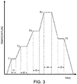
- this thermal treatment process may include heating the component to a first temperature T 1 and holding the component at that first temperature for a predetermined first time period t 1 , which has to be long enough to ensure a uniform temperature profile in the part and the evaporation of the binder contained in the brazing paste/material.
- the first hold temperature T 1 should be about 20-100K below the onset of ⁇ ' formation, which typically goes along with a reduction of the thermal expansion coefficient of the DMLM material.
- the high heating rate shall suppress as much as possible the formation of the ⁇ ' phase in the intermediate low ductility temperature range, where the DMLM part is brittle and where there is therefore a high risk of severe cracking. Still, it is often not possible even with such high heating rates v 2 to completely avoid the formation of macro cracks. Macro cracks form in particular at locations, where a high amount of frozen internal stress from processing is present or where the component design is not optimized leading to local stress peaks. In many cases, the cracks that need to be repaired thus occur during the temperature ramp from T 1 to the upper temperature T 2 .
- T 2 is greater than or equal to about 850°C and chosen high enough, that the high-strength DMLM material has again become ductile allowing the relaxation of remaining internal stresses in the DMLM part.
- T 2 is kept below the solidus temperature of the chosen braze alloy material to avoid partial flow of braze material 120 into the cracks 122, that may have formed during the transition from T 1 to T 2 .
- the heating or dwell time t 2 at T 2 ensures again a homogeneous temperature profile of the DMLM component, before a further temperature increase to T 3 is initiated. At the same time most of the remaining residual stresses will have relaxed after the hold or dwell time t 2 .
- the temperature is further increased at a rate v 3 of about 15-30K/minute to a temperature level T 3 and held there for dwell time t 3 , which temperature is set above the liquidus temperature of the braze material 120.
- the temperature level T 3 is chosen approximately 30K to 100K below the final recrystallisation temperature T 4 of the DMLM alloy.
- the braze material 120 becomes liquid. If a crack 122 had formed previously during the same heat treatment cycle the braze material can now flow into the crack 122 and fill it. Braze material 120 will then remain in the liquid state during the dwell time at the recrystallisation temperature T 4 .
- the component is slowly cooled down at a rate v 5 ⁇ -5K/min to another intermediate temperature T 5 and held there for a dwell time t 5 , which temperature is set to a level, where the braze becomes again solid.
- T 5 shall not be set more than 50K below the solidus temperature of the braze and the slow cooling from T 4 to T 5 shall prevent failures in the repaired braze joint due to fast cooling of the still ductile braze material.
- the cooling rate v 6 to ambient temperature is increased to values in the range from -15K/min to -50K/min to remain compliant with other microstructural requirements of the component until finally ambient temperature is reached.
- the horizontal axis is time and the vertical axis is temperature
- the first temperature T 1 is lower than the second temperature T 2
- the third temperature T 3 is higher than the second temperature T 2
- the final recrystallisation temperature T 4 is higher than T 3 .
- This five-tiered thermal treatment is one example only and more or less than four heating temperatures and one intermediate cooling temperature may be employed as desired for the specific component or material used.
- the methods described herein provide components having sealed cracks as compared with as-printed and thermally treated additively manufactured components.
- the methods disclosed herein may also seal surface cracks present on external and internal surfaces that are artifacts of the additive manufacturing process.
- Treated components demonstrate enhanced surface properties that confer enhanced resistance to corrosion, oxidation, and erosion, as well as increased lifetime.
- the proposed method significantly increases the yield of additive DMLM production, in particular, for components made from high-strength precipitation hardened Ni-superalloys, which are difficult to manufacture without severe defects.
- a technical advantage of the present method and heat treatment includes higher quality, improved yield and greater longevity of additively manufactured parts. Another advantage is reduction of cost associated with repairs as no separate braze repair cycle is required. Additionally, no expensive and time-consuming cleaning process for the cracks is required since such cracks form in a vacuum atmosphere and as a consequence are not oxidized. Another advantage is the option of selecting high-strength powder materials for the additively manufactured parts, including nickel-based superalloys with a high content of the strengthening ⁇ ' phase. These parts may now be heat treated according to the instant invention with braze material to seal cracks or other defects.
Description
- The present invention is directed to methods of manufacturing heat treated articles that are formed, at least in part, by additive manufacturing. More particularly, aspects of the present invention relate to methods of manufacturing components and articles, such as components of turbines, having heat treatment to fill cracks formed during thermal treatment and for enhanced performance, extended part life and reduced scrap amounts.
- Metal additive manufacturing methods enable manufacturers to create end-use metal articles that often outperform those produced with traditional machining and casting techniques. These methods may also enable the manufacture of parts that cannot otherwise be made by conventional methods. And they may provide the benefit of significantly reduced manufacturing costs. Once those articles are installed for end-use, they contribute to cost savings because of one or more of light weight, high strength, better functionality and precise fit. In the context of turbines, particularly gas or steam turbines, a variety of components or portions thereof may be additively manufactured, including, for example: turbine components selected from the group consisting of a hot gas path component, a shroud, a blade (or bucket), a nozzle (vane), and a seal. In some particular examples, combustor components and hot gas path components may be manufactured by additive processes to enable forming of complex geometries without the requirement for extensive post processing, including, but not limited to, nozzle bars, micromixer plenums, combustion flex tips and microchannel cooled shrouds.
- Though there are many benefits to be realized with additive manufacturing, in contrast to some conventional manufacturing techniques, articles that are additively manufactured may have surface features that have complex shapes. These complex shapes can be prone to cracking during thermal treatment. Thus, while many advantages can be achieved through additive manufacturing, a drawback is that the resultant cracks can adversely affect performance both in terms of mechanical integrity, the flow dynamics and leakage, and in some cases the parts cannot be used due to compromised flow integrity due to the gaps and cracks. In case repair approaches are implemented to avoid scraping the article, the part would normally first require a sophisticated cleaning process, a fluoride ion cleaning, to remove the oxides from the crack. Finally, a high temperature vacuum brazing process could be implemented to heal the surface cracks.
- Accordingly, there is a need in the art for a treatment to reduce cracking in additively manufactured parts that must be thermally treated after the build process.
-
US2018/0230584A1 suggests manufactured articles, and methods of manufacturing enhanced surface smoothed components and articles. More particularly, surface smoothed components and articles, such as combustor components of turbine engines, having surface treatment conferring reduced roughness for enhanced performance and reduced wear related reduction in part life. More in particular, the treatment may comprise applying a brazed coating covering the entire component or sections of the article on the external and internal surfaces thereof.DE 10 2017 208 659 A1 discloses a construction chamber for the additive production of components by laser buildup welding, wherein powdered material supplied in the process is supplied by means of a powder hose. In one embodiment, the powder hose comprises two partial hoses, in each of which a different powder material can be provided, wherein a mixture of a superalloy with a brazing material can be provided in particular in at least one hose. A method for manufacturing a component by means of the construction chamber is further provided. InWO 2015/161980 A1 a method for producing a component, in particular a turbine component, is suggested in which a base component is produced from a metal alloy. A powder containing or consisting of a brazing material is applied two-dimensionally to the outer surface of the base component by a thermal spray process, and subsequently the base component with the powder layer is subjected to a high-temperature brazing process in order to seal cracks in the outer surface of the base component. Further art is disclosed inEP 1 258 545 -
EP 2 944 402 discloses a method of post-built up heat treatment of an additively manufactured high strength component made of a gamma-prime (y') strengthened superalloy based on Ni or Co or Fe or combinations thereof. An application of a rapid heating-up rate of 25 to 60 °C/min in a specific temperature range during the first post-built heat treatment after additive manufacturing avoids or at least minimizes the gamma-prime precipitation in the component during heat-up. According to the teaching ofEP 2 944 402 , this results in crack-free components/articles compared to significant cracking present in conventionally heat treated components. - The herein claimed invention resides in the subject matter set forth in the claims.
- Other features and advantages of the present invention will be apparent from the following more detailed description of the preferred embodiment, taken in conjunction with the accompanying drawings which illustrate, by way of example, the principles of the invention.
-
-
FIG. 1 is a schematic view of a component as may be treated with the herein claimed method. -
FIG. 2 illustrates a schematic depicting a portion of an additively manufactured component treated in accordance with the herein claimed method. -
FIG. 3 illustrates an example of a thermal treatment process for an additively manufactured component treated in accordance with an embodiment of the herein disclosed method. - In accordance with the invention, methods are provided for filling cracks that form in a component during a thermal treatment process. The component may be a gas or steam turbine component. In accordance with the various aspects, the components are formed by one or more of various additive manufacturing methods, such as, for example, direct metal laser melting ("DMLM") made components. Representative examples of components include additively manufactured (by, e.g., DMLM) gas or steam turbine components, including but not limited to any one or more of a combustor, a combustion liner, a transition piece, a hot gas path component, a shroud, a blade (or bucket), a nozzle (vane), a seal, and combinations thereof. In some examples, the components include honeycombs, bucket tips, seals, and fins. In some particular examples, combustor components and hot gas path components may be manufactured by additive processes to enable forming of complex geometries without the requirement for extensive post processing, particularly components having micro-channels and other complex internal passages for cooling, including, but not limited to, nozzle bars, micromixer plenums, combustion flex tips and microchannel cooled shrouds.
- In accordance with the invention, a component or portion thereof is formed by an additive, or "three-dimensional" (3D) printing process. The additively manufactured component or portion is further processed by application of a braze material, the braze material is provided in select locations to fill subsequent cracks that are formed during a thermal treatment process, i.e. on component locations where cracks are expected or where cracks have occurred previously in similar components. According to the methods, the braze material is applied and brazed with a suitable brazing technique as required by the specific braze material and base material.
- Additive manufacturing methods generally include any manufacturing method for making and/or forming net or near-net shape structures. As used herein, the phrase "near-net" refers to a structure, such as the component, being formed with a geometry and size very similar to the final geometry and size of the structure, requiring little or no machining and processing after the additive method. As used herein, the phrase "net" refers to the structure being formed with a geometry and size requiring no machining and processing. The structure formed by the additive manufacturing method includes any suitable geometry, such as, but not limited to, square, rectangular, triangular, circular, semi-circular, oval, trapezoidal, octagonal, pyramidal, geometrical shapes having features formed therein, any other geometrical shape, or a combination thereof. For example, the additive method may include forming cooling features.
- In general, additive manufacturing processes comprise distributing a material to a selected region on a support or substrate/base and selectively melting or sintering the material with a laser or electron beam, or an equivalent process. A predetermined design file or two-dimensional slices of a three-dimensional file, for example, may be utilized from a computer-aided design program for the formation of the component or portion. The material may be in the form of atomized powder. Examples of additive manufacturing, or three-dimensional printing processes include, but are not limited to, the processes known to those of ordinary skill in the art as Direct Metal Laser Melting ("DMLM"), Direct Metal Laser Sintering ("DMLS"), Selective Laser Sintering ("SLS"), Selective Laser Melting ("SLM"), Electron Beam Melting ("EBM') as well as 'blown powder' additive manufacturing processes, generally known as laser cladding, Laser Powder Fusion ('LPF'), Direct Metal Laser Deposition ('DMLD'), Laser Metal Deposition ('LMD'), or Laser Metal Forming ('LMF'). As used herein, the term "three-dimensional printing process" refers to the processes described above as well as other suitable current or future processes that include the build-up of materials layer by layer. Suitable materials for three-dimensional printing processes may include, but are not limited to, plastic, thermoplastic, metal, metallic, ceramic, other suitable materials, or a combination thereof. In particular examples, suitable materials for the atomized powder may include, but are not limited to, stainless steel, tool steel, cobalt chrome, titanium, nickel, aluminum, alloys thereof, and combinations thereof.
- Thus, the method for fabricating a component or portion according to the present invention includes, in various examples, providing a metallic powder to a substrate surface, heating the metallic powder to a temperature sufficient to join at least a portion of the metallic powder to form an initial layer, and sequentially forming additional layers over the initial layer to form a component or portion thereof. The heating of the metallic powder includes controllably directing a focused energy source toward the metallic powder. Suitable focused energy sources include, but are not limited to, a laser device, an electron beam device, or a combination thereof. The parameters of the focused energy source will depend upon the material of the metallic powder used to form the formed component or portion and/or a desired thickness of each layer of the build.
- In some particular embodiments, the material for the atomized powders may include metal alloys, including nickel-based superalloys and cobalt-based superalloys, stainless and alloy steels, and titanium, aluminum and vanadium alloys. A suitable example of a cobalt-based alloy may have a formula (by mass) of Co-0.39-0.41Cr-0.19-0.21Ni-0.14-0.16Fe-0.113-0.205-Mo0.06-0.08-Mn0.015-0.025 (commercially available as Co-Cr-Ni alloy). A suitable example of a nickel-based alloy may have a formula (by mass) of Fe-0.50-0.55Ni-0.17-0.21Cr-0.028-0.033Mo-0.0475-0.055Nb-0.01Co-0.0035Mn-0.002-0.008Cu-0.0065-0.0115Al-0.003Ti (commercially available as Inconel 718) or a formula (by mass) of Ni-0.20-0.23Cr-0.05Fe-0.08-0.10Mo-0.0315-0.0415 Nb+Ta-0.01Co-0.005Mn-0.004Al-0.004Ti (commercially available as Inconel 625). Suitable examples of titanium-based alloys include those known by the trade names Ti-6Al-4Va and Aluminum 6061. In various non-limiting examples, components may include any suitable material, for example, stainless steel, a nickel-based alloy, an iron-based alloy, or any other suitable metal or metallic material. In one embodiment the component or portion thereof, is formed of a stainless steel and/or a nickel-based alloy, such as Hastelloy® X, the aforementioned material being discussed herein as merely illustrative and non-limiting. In some exemplary embodiments, materials for the printed component are selected from CoCrMo (Co-28Cr-6Mo) and Haynes 282 (Ni-20Cr-10Co-8Mo-1.5Al-2Ti), or high-strength, precipitation hardened Ni-superalloys such as Rene108 (Ni-23Cr-11.5Fe-4.2P-6.4Si), Rene80 (60Ni-14Cr-9.5Co-5Ti-4Mo-4W-3Al-0.17C-0.015B-0.03Zr), Inconel 738 (Ni-16Cr-8.5Co-1.7Mo-3.5Al-3.5Ti-1.7Ta-2.5W-0.05Zr-0.09C-0.01B-2Nb) and CM247 (Ni-0.07C-8.1Cr-9.2Co-9.5W-0.5Mo-3.2Ta-5.6Al-0.7Ti-1.4Hf-0.015B-0.015Zr). The metallic powder may be a nickel-based superalloy, a cobalt-based superalloy, an iron-based superalloy, and combinations thereof.
- Once formed, the component or portion thereof is further processed by application of a braze material. It will be appreciated that the terms "braze", "brazing". "braze film", "braze material", "braze paste" and "braze coating" as used herein are with reference to surface treatment of a component or portion, such as a turbine component, wherein the process does not include joining workpieces, but rather is performed to affix a braze material directly to the surface of the component to achieve benefits conferred by the resultant braze layer or fill.
- In some embodiments according to the invention, the techniques of vacuum brazing are used. As used herein, vacuum brazing means and refers to a process that offers the advantages of providing clean, superior, flux-free braze joints and surfaces of high integrity and strength. The process is performed inside a vacuum chamber vessel for a period of time from about 10-30 minutes at a typical pressure of not more than 8 × 10⁻⁴ torr, wherein uniform temperatures typically in the range from about 1500° F to about 2370° F (815°C - 1300°C) are maintained on the work piece under continuous heat to thereby reduce or eliminate the stress that can be introduced by other methods where heating and cooling cycles can occur.
- Referring now to the drawings,
FIG. 1 is a schematic depicting a portion of an additively manufacturedcomponent 100 treated in accordance with the invention. In accordance with this representative example, abraze material 110 is applied to or disposed on at least a portion of thecomponent 100, such as anouter surface 105. Thebraze material 110 is located in expectedcrack locations 120, that may occur during the thermal treatment. Generally, the maximum process temperature is given by the base metal requirements and it could require some compromises from the brazing side. In case the brazing alloy would normally require a lower temperature, a strong flow and spread of the brazing alloy on the base metal could be expected. In order to limit this phenomenon, stop-off in form of spray could be used to completely cover the brazing paste and constrain the flow of braze to the location affected by crack formation. The high cooling rate in direct metal laser melting (DMLM) generates fine grains. Therefore, an increase in tensile strength, hardness and low-cycle fatigue resistance along with a reduction in creep strength is common for DMLM made parts or components. A subsequent annealing or recrystallization process can give a good combination of ductility, strength and creep strength for direct metal laser melted components. However, this thermal treatment (annealing/recrystallization) process can also cause cracks to form in additively manufactured parts. This is particularly true for DMLM components made from precipitation hardened Ni-superalloys, such as Rene80, Rene108, CM247 or Inconel 738. Traditionally, these are casting alloys with very high-strength at elevated operation temperature grace to the precipitation of a strengthening γ' phase. In contrast to the conventional manufacturing by casting, additive manufacturing by DMLM does not generate γ' precipitations in an as-built part or component. Instead, the γ' precipitations only form during the first post-DMLM heat treatment. The formation of this strengthening phase happens in a temperature range, where the component is more brittle than at room temperature. Moreover, the phase transformation induces additional internal stresses, which in combination with the embrittlement can lead to severe cracking. Our inventive approach is to locatebraze material 110 selectively on these expected crack locations so that the braze can fill and join the crack surfaces in the base material of thecomponent 100 in-situ. The crack can thus be healed in the same heat treatment cycle while the component is still in the vacuum furnace at elevated temperature. On the one hand this ensures excellent braze wettability, as no oxide layer has formed, when the cracks occur. On the other hand, this has a significant commercial benefit, as the effort and cost for a fluoride ion cleaning process required to remove oxides from the crack and the subsequent braze repair cycle can be avoided. - The
component 100 or portion thereof is characterized in some examples as havingbraze material 110 applied to any one or more of an internal surface (as long as it can be accessed for braze paste and braze stop application) and an external surface on a metallic substrate, which surfaces may include any one or more of planes, corners, curves, and contours and may further include cracks or other gaps on the surface and penetrating into the substrate ofcomponent 100. With specific reference again toFIG 1 , thecomponent 100 has expectedcrack locations 120, which may be in known areas susceptible to cracking or in regions with complex shapes. According to the methods, and as depicted inFIG 1 , thebraze material 110 is applied after the additive manufacturing process of buildingcomponent 100. - In accordance with the methods, the
braze material 110 comprises known or novel low or high melt materials, and in particular, for use with nickel-based superalloys, the braze materials are particularly metallurgically compatible with such nickel-based superalloys. In accordance with the example, the braze material includes, but is not limited to, metal alloys and superalloys, including nickel-based superalloys and cobalt-based superalloys, alloys and combinations thereof. Suitable examples of a nickel-based alloy may have a formula (by mass) of Ni-14Cr-10Co-3.5Al-2.5Ta-2.75B-0.05Y (commercially available as Amdry DF-4B from Oerlikon Metco, located in Westbury, New York) or a formula (by mass) of Ni-19Cr-10Si (commercially available as BNi-5 from many providers, including Wall Colmonoy, located in Madison Heights, Michigan). Of course, it will be appreciated that other base materials may be used for forming components by additive manufacturing, and as such, other braze materials may be selected, which may be high melt, low melt or other than high/low melt. - The proposed manufacturing method includes a tailored heat treatment, which is designed to meet simultaneously two requirements. On the one hand it ensures the microstructural requirements of the DMLM part or component by an appropriate recrystallization (ReX), on the other hand, the temperature cycle allows simultaneously an in-situ braze repair, if cracks are formed at expected locations.
-
FIG. 2 illustrates a schematic depicting a portion of an additively manufacturedcomponent 100 treated in accordance with standard procedures. Thecomponent 100 has been thermally treated andcracks 122 formed in expected crack locations 120 (as shown inFIG. 1 ). Such crack formation during the first heat treatment cycle is very likely for precipitation hardened Ni-superalloys processed by DMLM. The proposed in-situ repair method discloses a method, where such cracks can be healed in the same heat treatment cycle, when and where the cracks occur. - Referring to
FIG. 3 , this thermal treatment process may include heating the component to a first temperature T1 and holding the component at that first temperature for a predetermined first time period t1, which has to be long enough to ensure a uniform temperature profile in the part and the evaporation of the binder contained in the brazing paste/material. If the component is made from a precipitation hardened Ni-superalloy, the first hold temperature T1 should be about 20-100K below the onset of γ' formation, which typically goes along with a reduction of the thermal expansion coefficient of the DMLM material. Once the component has reached a uniform temperature after t1, thecomponent 100 is quickly ramped up to a second temperature T2 at a high ramp rate v2 >20K/min. The high heating rate shall suppress as much as possible the formation of the γ' phase in the intermediate low ductility temperature range, where the DMLM part is brittle and where there is therefore a high risk of severe cracking. Still, it is often not possible even with such high heating rates v2 to completely avoid the formation of macro cracks. Macro cracks form in particular at locations, where a high amount of frozen internal stress from processing is present or where the component design is not optimized leading to local stress peaks. In many cases, the cracks that need to be repaired thus occur during the temperature ramp from T1 to the upper temperature T2. In a preferred embodiment, T2 is greater than or equal to about 850°C and chosen high enough, that the high-strength DMLM material has again become ductile allowing the relaxation of remaining internal stresses in the DMLM part. At the same time, T2 is kept below the solidus temperature of the chosen braze alloy material to avoid partial flow ofbraze material 120 into thecracks 122, that may have formed during the transition from T1 to T2. The heating or dwell time t2 at T2 ensures again a homogeneous temperature profile of the DMLM component, before a further temperature increase to T3 is initiated. At the same time most of the remaining residual stresses will have relaxed after the hold or dwell time t2. Thereafter, the temperature is further increased at a rate v3 of about 15-30K/minute to a temperature level T3 and held there for dwell time t3, which temperature is set above the liquidus temperature of thebraze material 120. Ideally, the temperature level T3 is chosen approximately 30K to 100K below the final recrystallisation temperature T4 of the DMLM alloy. During the temperature increase from T3 to T4, thebraze material 120 becomes liquid. If acrack 122 had formed previously during the same heat treatment cycle the braze material can now flow into thecrack 122 and fill it.Braze material 120 will then remain in the liquid state during the dwell time at the recrystallisation temperature T4. Contrary to the previous temperature ramp, temperature increases now happen at a slow heating rate v4 <5K/min to avoid temperature overshoots that could lead to local incipient melting. The component is kept at T4 for a recrystallization dwell time t4, which has to be long enough to obtain the desired recrystallization microstructure of the DMLM part. At the same time,braze material 120 completely fills thecrack 122 and braze diffusion occurs leading to a more homogeneous elemental distribution in the zone of crack repair. In some cases, the recrystallisation temperature T4 may be above typical temperatures recommendations of braze suppliers. As a positive side effect of such high temperatures T4, diffusion rates are higher and the formation of detrimental brittle phases in the braze joint is significantly reduced. Following the recrystallisation of the DMLM part and crack healing at T4, the component is slowly cooled down at a rate v5 < -5K/min to another intermediate temperature T5 and held there for a dwell time t5, which temperature is set to a level, where the braze becomes again solid. T5 shall not be set more than 50K below the solidus temperature of the braze and the slow cooling from T4 to T5 shall prevent failures in the repaired braze joint due to fast cooling of the still ductile braze material. After reaching T5, the cooling rate v6 to ambient temperature is increased to values in the range from -15K/min to -50K/min to remain compliant with other microstructural requirements of the component until finally ambient temperature is reached. In this example, the horizontal axis is time and the vertical axis is temperature, and the first temperature T1 is lower than the second temperature T2, the third temperature T3 is higher than the second temperature T2 and the final recrystallisation temperature T4 is higher than T3. This five-tiered thermal treatment is one example only and more or less than four heating temperatures and one intermediate cooling temperature may be employed as desired for the specific component or material used. - In accordance with the various embodiments, the methods described herein provide components having sealed cracks as compared with as-printed and thermally treated additively manufactured components. The methods disclosed herein may also seal surface cracks present on external and internal surfaces that are artifacts of the additive manufacturing process. Treated components demonstrate enhanced surface properties that confer enhanced resistance to corrosion, oxidation, and erosion, as well as increased lifetime. At the same time the proposed method significantly increases the yield of additive DMLM production, in particular, for components made from high-strength precipitation hardened Ni-superalloys, which are difficult to manufacture without severe defects.
- Thus, a technical advantage of the present method and heat treatment includes higher quality, improved yield and greater longevity of additively manufactured parts. Another advantage is reduction of cost associated with repairs as no separate braze repair cycle is required. Additionally, no expensive and time-consuming cleaning process for the cracks is required since such cracks form in a vacuum atmosphere and as a consequence are not oxidized. Another advantage is the option of selecting high-strength powder materials for the additively manufactured parts, including nickel-based superalloys with a high content of the strengthening γ' phase. These parts may now be heat treated according to the instant invention with braze material to seal cracks or other defects.
- While the invention has been described with reference to a preferred embodiment, it will be understood by those skilled in the art that various changes may be made and equivalents may be substituted for elements thereof without departing from the scope of the invention. In addition, many modifications may be made to adapt a particular situation or material to the teachings of the invention without departing from the essential scope thereof. Therefore, it is intended that the invention not be limited to the particular embodiment disclosed as the best mode contemplated for carrying out this invention, but that the invention will include all embodiments falling within the scope of the appended claims.
Claims (6)
- A method for fabricating a component, comprising the steps of:forming an additively manufactured component (100) having sequentially joined layers of a metallic powder by an additive manufacturing process;wherein the additive manufacturing process includes providing a metallic powder to a substrate surface, heating the metallic powder to a temperature sufficient to join at least a portion of the metallic powder to form an initial layer, and sequentially forming additional layers over the initial layer to form a component or portion thereof, wherein further heating of the metallic powder controllably directing a focused energy source toward the metallic powder,the method further comprising identifying expected crack locations (120) on a surface (105) of the additively manufactured component;applying a braze material to the expected crack locations (120), wherein the braze material (110) is only and selectively applied to the expected crack locations;heating the additively manufactured component (100) to at least two desired heating temperatures (T1-T4) for at least two desired heating or dwell time periods (t1-t4); wherein the heating comprises heating the additively manufactured component to a first temperature (T1) and maintaining the additively manufactured component at the first temperature for a first dwell time (t1) and subsequently heating the additively manufactured component to a second temperature (T2) and maintaining the additively manufactured component at the second temperature for a second dwell time (t2), wherein the first temperature is lower than the second temperature, wherein the second temperature is at a temperature level where stress relaxation can occur in the additively manufactured component and where the braze material remains in a solid state,the method further comprising cooling the additively manufactured component to a cooling temperature (T5) for a dwell time period (t5); andwherein the braze material (110) fills in a crack (122) formed during at least one of the heating steps.
- The method for fabricating a component according to the preceding claim, wherein the additively manufactured component (100) is formed from a precipitation hardened nickel-based superalloy, which forms a γ' phase.
- The method for fabricating a component according to the preceding claim, wherein the braze material (110) is comprised of a nickel-based alloy or a cobalt-based alloy.
- The method for fabricating a component according to claim 2, wherein the heating step heats the additively manufactured component to a first temperature and then subsequently heats the additively manufactured component to a second temperature, and then subsequently heats the additively manufactured component to a third temperature, and wherein the first temperature is lower than the second temperature, and the second temperature is lower than the third temperature and where the third temperature is kept at 30K to 100K below a recrystallization temperature of the additively manufactured component.
- The method for fabricating a component according to claim 2, wherein the heating step heats the additively manufactured component to a first temperature and then subsequently heats the additively manufactured component to a second temperature, and then subsequently heats the additively manufactured component to a third temperature, and then subsequently heats the additively manufactured component to a fourth temperature and wherein the first temperature is lower than the second temperature, and the second temperature is lower than the third temperature, and the third temperature is lower than the fourth temperature and wherein recrystallization of the additively manufactured component occurs at the fourth temperature.
- The method for fabricating a component according to claim 2, wherein the additive manufacturing process is selected from the group consisting of direct metal laser melting, direct metal laser sintering, selective laser melting, electron beam melting, and combinations thereof.
Applications Claiming Priority (1)
| Application Number | Priority Date | Filing Date | Title |
|---|---|---|---|
| US16/270,107 US11077512B2 (en) | 2019-02-07 | 2019-02-07 | Manufactured article and method |
Publications (2)
| Publication Number | Publication Date |
|---|---|
| EP3693105A1 EP3693105A1 (en) | 2020-08-12 |
| EP3693105B1 true EP3693105B1 (en) | 2022-11-16 |
Family
ID=69468509
Family Applications (1)
| Application Number | Title | Priority Date | Filing Date |
|---|---|---|---|
| EP20155510.9A Active EP3693105B1 (en) | 2019-02-07 | 2020-02-04 | Method for manufacturing an article |
Country Status (3)
| Country | Link |
|---|---|
| US (1) | US11077512B2 (en) |
| EP (1) | EP3693105B1 (en) |
| JP (1) | JP2020147846A (en) |
Families Citing this family (6)
| Publication number | Priority date | Publication date | Assignee | Title |
|---|---|---|---|---|
| GB2565063B (en) | 2017-07-28 | 2020-05-27 | Oxmet Tech Limited | A nickel-based alloy |
| GB2587635B (en) * | 2019-10-02 | 2022-11-02 | Alloyed Ltd | A Nickel-based alloy |
| CN113462997B (en) * | 2021-06-30 | 2022-08-02 | 中国航发动力股份有限公司 | Heat treatment method for improving weld performance after electron beam welding |
| CN113814412A (en) * | 2021-09-18 | 2021-12-21 | 航发优材(镇江)增材制造有限公司 | Crack control method in selective laser melting process of high-strength aluminum alloy component |
| CN114211000A (en) * | 2021-12-16 | 2022-03-22 | 上海工程技术大学 | Selective laser melting method for reducing alloy surface cracks |
| US20240082940A1 (en) * | 2022-09-09 | 2024-03-14 | Pratt & Whitney Canada Corp. | Additively depositing braze material |
Citations (1)
| Publication number | Priority date | Publication date | Assignee | Title |
|---|---|---|---|---|
| EP2944402A1 (en) * | 2014-05-12 | 2015-11-18 | Alstom Technology Ltd | Method for post-built heat treatment of additively manufactured components made of gamma-prime strengthened superalloys |
Family Cites Families (8)
| Publication number | Priority date | Publication date | Assignee | Title |
|---|---|---|---|---|
| DE60107541T2 (en) | 2001-05-14 | 2005-12-08 | Alstom Technology Ltd | Method for isothermal brazing of monocrystalline objects |
| DE102014207622A1 (en) | 2014-04-23 | 2015-10-29 | Siemens Aktiengesellschaft | Method for producing a component |
| US9931695B2 (en) | 2014-09-25 | 2018-04-03 | General Electric Company | Article and method for making an article |
| US9931814B2 (en) | 2014-09-25 | 2018-04-03 | General Electric Company | Article and method for making an article |
| US9849510B2 (en) | 2015-04-16 | 2017-12-26 | General Electric Company | Article and method of forming an article |
| US20160354842A1 (en) | 2015-06-07 | 2016-12-08 | General Electric Company | Additive manufacturing methods and hybrid articles using brazeable additive structures |
| US10174414B2 (en) * | 2017-02-16 | 2019-01-08 | General Electric Company | Manufactured article and method |
| DE102017208659A1 (en) | 2017-05-22 | 2018-11-22 | Siemens Aktiengesellschaft | Use of powder hoses for feeding solder mixtures in the generative production of components by means of laser deposition welding |
-
2019
- 2019-02-07 US US16/270,107 patent/US11077512B2/en active Active
-
2020
- 2020-01-28 JP JP2020011344A patent/JP2020147846A/en active Pending
- 2020-02-04 EP EP20155510.9A patent/EP3693105B1/en active Active
Patent Citations (1)
| Publication number | Priority date | Publication date | Assignee | Title |
|---|---|---|---|---|
| EP2944402A1 (en) * | 2014-05-12 | 2015-11-18 | Alstom Technology Ltd | Method for post-built heat treatment of additively manufactured components made of gamma-prime strengthened superalloys |
Also Published As
| Publication number | Publication date |
|---|---|
| JP2020147846A (en) | 2020-09-17 |
| EP3693105A1 (en) | 2020-08-12 |
| US20200254547A1 (en) | 2020-08-13 |
| US11077512B2 (en) | 2021-08-03 |
Similar Documents
| Publication | Publication Date | Title |
|---|---|---|
| EP3693105B1 (en) | Method for manufacturing an article | |
| EP1803521B1 (en) | Machine components and methods of fabricating and repairing | |
| EP3363585B1 (en) | A manufactured article and method | |
| US5395584A (en) | Nickel-base superalloy compositions | |
| RU2624884C2 (en) | Localized repair of the component from superalloy | |
| EP3072612A2 (en) | Component and method for fabricating a component | |
| EP2543467A1 (en) | Method of welding a gamma-prime precipitate strengthened material | |
| US20180345396A1 (en) | Machine components and methods of fabricating and repairing | |
| US5890274A (en) | Method of producing a coating layer on a localized area of a superalloy component | |
| US20020189722A1 (en) | Turbine engine component having wear coating and method for coating a turbine engine component | |
| JP6595593B2 (en) | Method for manufacturing turbine engine component | |
| US11090770B2 (en) | Method of forming a component | |
| KR20150106007A (en) | Localized repair of superalloy component | |
| EP3823783B1 (en) | Section replacement of a turbine airfoil with a metallic braze presintered preform | |
| RU2763527C1 (en) | Pre-sintered billet for repair of gas turbine service starting components | |
| EP1798316A1 (en) | Repair method of crystalline structures by epitaxy | |
| US11753724B2 (en) | Methods of forming desired geometry on superalloy part using powder mixture of low and high melt temperature superalloys | |
| EP3034229B1 (en) | Weld filler for superalloys | |
| EP3412784B1 (en) | Method of treating superalloy articles | |
| EP4299237A1 (en) | Method and system for thermal spraying braze alloy materials onto a nickel-based component to facilitate high density brazed joint with low discontinuities | |
| Simó Vesperinas | Development of method for processing brittle-hard materials using Laser Metal Deposition (LMD) |
Legal Events
| Date | Code | Title | Description |
|---|---|---|---|
| PUAI | Public reference made under article 153(3) epc to a published international application that has entered the european phase |
Free format text: ORIGINAL CODE: 0009012 |
|
| STAA | Information on the status of an ep patent application or granted ep patent |
Free format text: STATUS: THE APPLICATION HAS BEEN PUBLISHED |
|
| AK | Designated contracting states |
Kind code of ref document: A1 Designated state(s): AL AT BE BG CH CY CZ DE DK EE ES FI FR GB GR HR HU IE IS IT LI LT LU LV MC MK MT NL NO PL PT RO RS SE SI SK SM TR |
|
| AX | Request for extension of the european patent |
Extension state: BA ME |
|
| STAA | Information on the status of an ep patent application or granted ep patent |
Free format text: STATUS: REQUEST FOR EXAMINATION WAS MADE |
|
| 17P | Request for examination filed |
Effective date: 20210211 |
|
| RBV | Designated contracting states (corrected) |
Designated state(s): AL AT BE BG CH CY CZ DE DK EE ES FI FR GB GR HR HU IE IS IT LI LT LU LV MC MK MT NL NO PL PT RO RS SE SI SK SM TR |
|
| STAA | Information on the status of an ep patent application or granted ep patent |
Free format text: STATUS: EXAMINATION IS IN PROGRESS |
|
| 17Q | First examination report despatched |
Effective date: 20210702 |
|
| REG | Reference to a national code |
Ref country code: DE Ref legal event code: R079 Ref document number: 602020006243 Country of ref document: DE Free format text: PREVIOUS MAIN CLASS: B22F0003105000 Ipc: B22F0005000000 |
|
| GRAP | Despatch of communication of intention to grant a patent |
Free format text: ORIGINAL CODE: EPIDOSNIGR1 |
|
| RIC1 | Information provided on ipc code assigned before grant |
Ipc: B23P 6/04 20060101ALN20220405BHEP Ipc: B33Y 80/00 20150101ALN20220405BHEP Ipc: B33Y 10/00 20150101ALN20220405BHEP Ipc: B23K 103/08 20060101ALN20220405BHEP Ipc: B23K 101/00 20060101ALN20220405BHEP Ipc: B22F 7/06 20060101ALN20220405BHEP Ipc: B22F 3/24 20060101ALN20220405BHEP Ipc: B22F 10/28 20210101ALN20220405BHEP Ipc: B22F 10/25 20210101ALN20220405BHEP Ipc: B22F 3/26 20060101ALN20220405BHEP Ipc: F01D 5/00 20060101ALI20220405BHEP Ipc: B33Y 40/20 20200101ALI20220405BHEP Ipc: B23K 35/30 20060101ALI20220405BHEP Ipc: B23K 35/02 20060101ALI20220405BHEP Ipc: B23K 26/342 20140101ALI20220405BHEP Ipc: B23K 15/00 20060101ALI20220405BHEP Ipc: B23K 1/00 20060101ALI20220405BHEP Ipc: B22F 10/64 20210101ALI20220405BHEP Ipc: B22F 5/04 20060101ALI20220405BHEP Ipc: B22F 5/00 20060101AFI20220405BHEP |
|
| STAA | Information on the status of an ep patent application or granted ep patent |
Free format text: STATUS: GRANT OF PATENT IS INTENDED |
|
| INTG | Intention to grant announced |
Effective date: 20220512 |
|
| GRAS | Grant fee paid |
Free format text: ORIGINAL CODE: EPIDOSNIGR3 |
|
| GRAA | (expected) grant |
Free format text: ORIGINAL CODE: 0009210 |
|
| STAA | Information on the status of an ep patent application or granted ep patent |
Free format text: STATUS: THE PATENT HAS BEEN GRANTED |
|
| AK | Designated contracting states |
Kind code of ref document: B1 Designated state(s): AL AT BE BG CH CY CZ DE DK EE ES FI FR GB GR HR HU IE IS IT LI LT LU LV MC MK MT NL NO PL PT RO RS SE SI SK SM TR |
|
| REG | Reference to a national code |
Ref country code: GB Ref legal event code: FG4D |
|
| REG | Reference to a national code |
Ref country code: CH Ref legal event code: EP |
|
| REG | Reference to a national code |
Ref country code: IE Ref legal event code: FG4D |
|
| REG | Reference to a national code |
Ref country code: DE Ref legal event code: R096 Ref document number: 602020006243 Country of ref document: DE |
|
| REG | Reference to a national code |
Ref country code: AT Ref legal event code: REF Ref document number: 1531469 Country of ref document: AT Kind code of ref document: T Effective date: 20221215 |
|
| REG | Reference to a national code |
Ref country code: LT Ref legal event code: MG9D |
|
| REG | Reference to a national code |
Ref country code: NL Ref legal event code: MP Effective date: 20221116 |
|
| REG | Reference to a national code |
Ref country code: AT Ref legal event code: MK05 Ref document number: 1531469 Country of ref document: AT Kind code of ref document: T Effective date: 20221116 |
|
| PG25 | Lapsed in a contracting state [announced via postgrant information from national office to epo] |
Ref country code: SE Free format text: LAPSE BECAUSE OF FAILURE TO SUBMIT A TRANSLATION OF THE DESCRIPTION OR TO PAY THE FEE WITHIN THE PRESCRIBED TIME-LIMIT Effective date: 20221116 Ref country code: PT Free format text: LAPSE BECAUSE OF FAILURE TO SUBMIT A TRANSLATION OF THE DESCRIPTION OR TO PAY THE FEE WITHIN THE PRESCRIBED TIME-LIMIT Effective date: 20230316 Ref country code: NO Free format text: LAPSE BECAUSE OF FAILURE TO SUBMIT A TRANSLATION OF THE DESCRIPTION OR TO PAY THE FEE WITHIN THE PRESCRIBED TIME-LIMIT Effective date: 20230216 Ref country code: LT Free format text: LAPSE BECAUSE OF FAILURE TO SUBMIT A TRANSLATION OF THE DESCRIPTION OR TO PAY THE FEE WITHIN THE PRESCRIBED TIME-LIMIT Effective date: 20221116 Ref country code: FI Free format text: LAPSE BECAUSE OF FAILURE TO SUBMIT A TRANSLATION OF THE DESCRIPTION OR TO PAY THE FEE WITHIN THE PRESCRIBED TIME-LIMIT Effective date: 20221116 Ref country code: ES Free format text: LAPSE BECAUSE OF FAILURE TO SUBMIT A TRANSLATION OF THE DESCRIPTION OR TO PAY THE FEE WITHIN THE PRESCRIBED TIME-LIMIT Effective date: 20221116 Ref country code: AT Free format text: LAPSE BECAUSE OF FAILURE TO SUBMIT A TRANSLATION OF THE DESCRIPTION OR TO PAY THE FEE WITHIN THE PRESCRIBED TIME-LIMIT Effective date: 20221116 |
|
| PG25 | Lapsed in a contracting state [announced via postgrant information from national office to epo] |
Ref country code: RS Free format text: LAPSE BECAUSE OF FAILURE TO SUBMIT A TRANSLATION OF THE DESCRIPTION OR TO PAY THE FEE WITHIN THE PRESCRIBED TIME-LIMIT Effective date: 20221116 Ref country code: PL Free format text: LAPSE BECAUSE OF FAILURE TO SUBMIT A TRANSLATION OF THE DESCRIPTION OR TO PAY THE FEE WITHIN THE PRESCRIBED TIME-LIMIT Effective date: 20221116 Ref country code: LV Free format text: LAPSE BECAUSE OF FAILURE TO SUBMIT A TRANSLATION OF THE DESCRIPTION OR TO PAY THE FEE WITHIN THE PRESCRIBED TIME-LIMIT Effective date: 20221116 Ref country code: IS Free format text: LAPSE BECAUSE OF FAILURE TO SUBMIT A TRANSLATION OF THE DESCRIPTION OR TO PAY THE FEE WITHIN THE PRESCRIBED TIME-LIMIT Effective date: 20230316 Ref country code: HR Free format text: LAPSE BECAUSE OF FAILURE TO SUBMIT A TRANSLATION OF THE DESCRIPTION OR TO PAY THE FEE WITHIN THE PRESCRIBED TIME-LIMIT Effective date: 20221116 Ref country code: GR Free format text: LAPSE BECAUSE OF FAILURE TO SUBMIT A TRANSLATION OF THE DESCRIPTION OR TO PAY THE FEE WITHIN THE PRESCRIBED TIME-LIMIT Effective date: 20230217 |
|
| PGFP | Annual fee paid to national office [announced via postgrant information from national office to epo] |
Ref country code: IT Payment date: 20230228 Year of fee payment: 4 Ref country code: DE Payment date: 20230119 Year of fee payment: 4 |
|
| PG25 | Lapsed in a contracting state [announced via postgrant information from national office to epo] |
Ref country code: NL Free format text: LAPSE BECAUSE OF FAILURE TO SUBMIT A TRANSLATION OF THE DESCRIPTION OR TO PAY THE FEE WITHIN THE PRESCRIBED TIME-LIMIT Effective date: 20221116 |
|
| PG25 | Lapsed in a contracting state [announced via postgrant information from national office to epo] |
Ref country code: SM Free format text: LAPSE BECAUSE OF FAILURE TO SUBMIT A TRANSLATION OF THE DESCRIPTION OR TO PAY THE FEE WITHIN THE PRESCRIBED TIME-LIMIT Effective date: 20221116 Ref country code: RO Free format text: LAPSE BECAUSE OF FAILURE TO SUBMIT A TRANSLATION OF THE DESCRIPTION OR TO PAY THE FEE WITHIN THE PRESCRIBED TIME-LIMIT Effective date: 20221116 Ref country code: EE Free format text: LAPSE BECAUSE OF FAILURE TO SUBMIT A TRANSLATION OF THE DESCRIPTION OR TO PAY THE FEE WITHIN THE PRESCRIBED TIME-LIMIT Effective date: 20221116 Ref country code: DK Free format text: LAPSE BECAUSE OF FAILURE TO SUBMIT A TRANSLATION OF THE DESCRIPTION OR TO PAY THE FEE WITHIN THE PRESCRIBED TIME-LIMIT Effective date: 20221116 Ref country code: CZ Free format text: LAPSE BECAUSE OF FAILURE TO SUBMIT A TRANSLATION OF THE DESCRIPTION OR TO PAY THE FEE WITHIN THE PRESCRIBED TIME-LIMIT Effective date: 20221116 |
|
| REG | Reference to a national code |
Ref country code: DE Ref legal event code: R097 Ref document number: 602020006243 Country of ref document: DE |
|
| PG25 | Lapsed in a contracting state [announced via postgrant information from national office to epo] |
Ref country code: SK Free format text: LAPSE BECAUSE OF FAILURE TO SUBMIT A TRANSLATION OF THE DESCRIPTION OR TO PAY THE FEE WITHIN THE PRESCRIBED TIME-LIMIT Effective date: 20221116 Ref country code: AL Free format text: LAPSE BECAUSE OF FAILURE TO SUBMIT A TRANSLATION OF THE DESCRIPTION OR TO PAY THE FEE WITHIN THE PRESCRIBED TIME-LIMIT Effective date: 20221116 |
|
| PLBE | No opposition filed within time limit |
Free format text: ORIGINAL CODE: 0009261 |
|
| STAA | Information on the status of an ep patent application or granted ep patent |
Free format text: STATUS: NO OPPOSITION FILED WITHIN TIME LIMIT |
|
| PG25 | Lapsed in a contracting state [announced via postgrant information from national office to epo] |
Ref country code: MC Free format text: LAPSE BECAUSE OF FAILURE TO SUBMIT A TRANSLATION OF THE DESCRIPTION OR TO PAY THE FEE WITHIN THE PRESCRIBED TIME-LIMIT Effective date: 20221116 |
|
| REG | Reference to a national code |
Ref country code: CH Ref legal event code: PL |
|
| REG | Reference to a national code |
Ref country code: BE Ref legal event code: MM Effective date: 20230228 |
|
| 26N | No opposition filed |
Effective date: 20230817 |
|
| PG25 | Lapsed in a contracting state [announced via postgrant information from national office to epo] |
Ref country code: LU Free format text: LAPSE BECAUSE OF NON-PAYMENT OF DUE FEES Effective date: 20230204 Ref country code: LI Free format text: LAPSE BECAUSE OF NON-PAYMENT OF DUE FEES Effective date: 20230228 Ref country code: CH Free format text: LAPSE BECAUSE OF NON-PAYMENT OF DUE FEES Effective date: 20230228 |
|
| REG | Reference to a national code |
Ref country code: DE Ref legal event code: R081 Ref document number: 602020006243 Country of ref document: DE Owner name: GENERAL ELECTRIC TECHNOLOGY GMBH, CH Free format text: FORMER OWNER: GENERAL ELECTRIC COMPANY, SCHENECTADY, NY, US |
|
| PG25 | Lapsed in a contracting state [announced via postgrant information from national office to epo] |
Ref country code: SI Free format text: LAPSE BECAUSE OF FAILURE TO SUBMIT A TRANSLATION OF THE DESCRIPTION OR TO PAY THE FEE WITHIN THE PRESCRIBED TIME-LIMIT Effective date: 20221116 |
|
| REG | Reference to a national code |
Ref country code: IE Ref legal event code: MM4A |
|
| PG25 | Lapsed in a contracting state [announced via postgrant information from national office to epo] |
Ref country code: IE Free format text: LAPSE BECAUSE OF NON-PAYMENT OF DUE FEES Effective date: 20230204 Ref country code: FR Free format text: LAPSE BECAUSE OF NON-PAYMENT OF DUE FEES Effective date: 20230228 |
|
| PG25 | Lapsed in a contracting state [announced via postgrant information from national office to epo] |
Ref country code: BE Free format text: LAPSE BECAUSE OF NON-PAYMENT OF DUE FEES Effective date: 20230228 |
|
| REG | Reference to a national code |
Ref country code: GB Ref legal event code: 732E Free format text: REGISTERED BETWEEN 20240222 AND 20240228 |