EP3693104A1 - Procédés de fabrication additive avec des particules mastiquées - Google Patents
Procédés de fabrication additive avec des particules mastiquées Download PDFInfo
- Publication number
- EP3693104A1 EP3693104A1 EP19213196.9A EP19213196A EP3693104A1 EP 3693104 A1 EP3693104 A1 EP 3693104A1 EP 19213196 A EP19213196 A EP 19213196A EP 3693104 A1 EP3693104 A1 EP 3693104A1
- Authority
- EP
- European Patent Office
- Prior art keywords
- particles
- masticated
- deposition
- faceted
- additive manufacturing
- Prior art date
- Legal status (The legal status is an assumption and is not a legal conclusion. Google has not performed a legal analysis and makes no representation as to the accuracy of the status listed.)
- Pending
Links
- 239000002245 particle Substances 0.000 title claims abstract description 244
- 238000000034 method Methods 0.000 title claims abstract description 100
- 238000004519 manufacturing process Methods 0.000 title claims abstract description 72
- 239000000654 additive Substances 0.000 title claims abstract description 46
- 230000000996 additive effect Effects 0.000 title claims abstract description 46
- 230000008021 deposition Effects 0.000 claims abstract description 167
- 230000008018 melting Effects 0.000 claims abstract description 11
- 238000002844 melting Methods 0.000 claims abstract description 11
- 238000000151 deposition Methods 0.000 claims description 167
- 239000000463 material Substances 0.000 claims description 43
- 239000000843 powder Substances 0.000 claims description 31
- PXHVJJICTQNCMI-UHFFFAOYSA-N Nickel Chemical compound [Ni] PXHVJJICTQNCMI-UHFFFAOYSA-N 0.000 claims description 16
- 238000009826 distribution Methods 0.000 claims description 14
- 229910045601 alloy Inorganic materials 0.000 claims description 13
- 239000000956 alloy Substances 0.000 claims description 13
- RTAQQCXQSZGOHL-UHFFFAOYSA-N Titanium Chemical compound [Ti] RTAQQCXQSZGOHL-UHFFFAOYSA-N 0.000 claims description 12
- 239000000155 melt Substances 0.000 claims description 12
- 229910052719 titanium Inorganic materials 0.000 claims description 12
- 239000010936 titanium Substances 0.000 claims description 12
- 238000012360 testing method Methods 0.000 claims description 11
- 238000011065 in-situ storage Methods 0.000 claims description 10
- 229910052782 aluminium Inorganic materials 0.000 claims description 9
- XAGFODPZIPBFFR-UHFFFAOYSA-N aluminium Chemical compound [Al] XAGFODPZIPBFFR-UHFFFAOYSA-N 0.000 claims description 9
- 229910000831 Steel Inorganic materials 0.000 claims description 8
- 229910052759 nickel Inorganic materials 0.000 claims description 8
- 239000010959 steel Substances 0.000 claims description 8
- 239000012798 spherical particle Substances 0.000 claims description 7
- 239000003674 animal food additive Substances 0.000 claims description 6
- 239000010410 layer Substances 0.000 description 13
- 238000012546 transfer Methods 0.000 description 7
- 230000008569 process Effects 0.000 description 6
- 238000009499 grossing Methods 0.000 description 5
- 229910052751 metal Inorganic materials 0.000 description 5
- 239000002184 metal Substances 0.000 description 5
- 239000012255 powdered metal Substances 0.000 description 5
- 230000008878 coupling Effects 0.000 description 4
- 238000010168 coupling process Methods 0.000 description 4
- 238000005859 coupling reaction Methods 0.000 description 4
- 239000011261 inert gas Substances 0.000 description 4
- 230000004048 modification Effects 0.000 description 4
- 238000012986 modification Methods 0.000 description 4
- 238000000879 optical micrograph Methods 0.000 description 4
- 238000001465 metallisation Methods 0.000 description 3
- 239000000203 mixture Substances 0.000 description 3
- 238000012545 processing Methods 0.000 description 3
- 229910001069 Ti alloy Inorganic materials 0.000 description 2
- 238000010586 diagram Methods 0.000 description 2
- 239000007789 gas Substances 0.000 description 2
- 230000018984 mastication Effects 0.000 description 2
- 238000010077 mastication Methods 0.000 description 2
- 150000002739 metals Chemical class 0.000 description 2
- 229920000642 polymer Polymers 0.000 description 2
- 230000009467 reduction Effects 0.000 description 2
- 238000007493 shaping process Methods 0.000 description 2
- RWSOTUBLDIXVET-UHFFFAOYSA-N Dihydrogen sulfide Chemical compound S RWSOTUBLDIXVET-UHFFFAOYSA-N 0.000 description 1
- UFHFLCQGNIYNRP-UHFFFAOYSA-N Hydrogen Chemical compound [H][H] UFHFLCQGNIYNRP-UHFFFAOYSA-N 0.000 description 1
- 230000004075 alteration Effects 0.000 description 1
- 239000004411 aluminium Substances 0.000 description 1
- QVGXLLKOCUKJST-UHFFFAOYSA-N atomic oxygen Chemical compound [O] QVGXLLKOCUKJST-UHFFFAOYSA-N 0.000 description 1
- 238000000889 atomisation Methods 0.000 description 1
- 230000008901 benefit Effects 0.000 description 1
- 230000015572 biosynthetic process Effects 0.000 description 1
- -1 but not limited to Substances 0.000 description 1
- 238000005266 casting Methods 0.000 description 1
- 238000001816 cooling Methods 0.000 description 1
- 230000003247 decreasing effect Effects 0.000 description 1
- 238000011161 development Methods 0.000 description 1
- 230000018109 developmental process Effects 0.000 description 1
- 230000007613 environmental effect Effects 0.000 description 1
- 239000012530 fluid Substances 0.000 description 1
- 230000004927 fusion Effects 0.000 description 1
- 238000009689 gas atomisation Methods 0.000 description 1
- 230000005484 gravity Effects 0.000 description 1
- 238000010438 heat treatment Methods 0.000 description 1
- 239000001257 hydrogen Substances 0.000 description 1
- 229910052739 hydrogen Inorganic materials 0.000 description 1
- 229910000037 hydrogen sulfide Inorganic materials 0.000 description 1
- 230000001939 inductive effect Effects 0.000 description 1
- 238000004372 laser cladding Methods 0.000 description 1
- 229910001338 liquidmetal Inorganic materials 0.000 description 1
- 238000005259 measurement Methods 0.000 description 1
- 230000003287 optical effect Effects 0.000 description 1
- 239000001301 oxygen Substances 0.000 description 1
- 229910052760 oxygen Inorganic materials 0.000 description 1
- 239000002356 single layer Substances 0.000 description 1
- 239000007787 solid Substances 0.000 description 1
- 238000007711 solidification Methods 0.000 description 1
- 230000008023 solidification Effects 0.000 description 1
- 238000001179 sorption measurement Methods 0.000 description 1
- 239000000126 substance Substances 0.000 description 1
- 239000000758 substrate Substances 0.000 description 1
- XLYOFNOQVPJJNP-UHFFFAOYSA-N water Chemical compound O XLYOFNOQVPJJNP-UHFFFAOYSA-N 0.000 description 1
Images


Classifications
-
- B—PERFORMING OPERATIONS; TRANSPORTING
- B22—CASTING; POWDER METALLURGY
- B22F—WORKING METALLIC POWDER; MANUFACTURE OF ARTICLES FROM METALLIC POWDER; MAKING METALLIC POWDER; APPARATUS OR DEVICES SPECIALLY ADAPTED FOR METALLIC POWDER
- B22F3/00—Manufacture of workpieces or articles from metallic powder characterised by the manner of compacting or sintering; Apparatus specially adapted therefor ; Presses and furnaces
- B22F3/115—Manufacture of workpieces or articles from metallic powder characterised by the manner of compacting or sintering; Apparatus specially adapted therefor ; Presses and furnaces by spraying molten metal, i.e. spray sintering, spray casting
-
- B—PERFORMING OPERATIONS; TRANSPORTING
- B22—CASTING; POWDER METALLURGY
- B22F—WORKING METALLIC POWDER; MANUFACTURE OF ARTICLES FROM METALLIC POWDER; MAKING METALLIC POWDER; APPARATUS OR DEVICES SPECIALLY ADAPTED FOR METALLIC POWDER
- B22F1/00—Metallic powder; Treatment of metallic powder, e.g. to facilitate working or to improve properties
- B22F1/06—Metallic powder characterised by the shape of the particles
- B22F1/065—Spherical particles
-
- B—PERFORMING OPERATIONS; TRANSPORTING
- B22—CASTING; POWDER METALLURGY
- B22F—WORKING METALLIC POWDER; MANUFACTURE OF ARTICLES FROM METALLIC POWDER; MAKING METALLIC POWDER; APPARATUS OR DEVICES SPECIALLY ADAPTED FOR METALLIC POWDER
- B22F1/00—Metallic powder; Treatment of metallic powder, e.g. to facilitate working or to improve properties
- B22F1/12—Metallic powder containing non-metallic particles
-
- B—PERFORMING OPERATIONS; TRANSPORTING
- B22—CASTING; POWDER METALLURGY
- B22F—WORKING METALLIC POWDER; MANUFACTURE OF ARTICLES FROM METALLIC POWDER; MAKING METALLIC POWDER; APPARATUS OR DEVICES SPECIALLY ADAPTED FOR METALLIC POWDER
- B22F1/00—Metallic powder; Treatment of metallic powder, e.g. to facilitate working or to improve properties
- B22F1/14—Treatment of metallic powder
-
- B—PERFORMING OPERATIONS; TRANSPORTING
- B22—CASTING; POWDER METALLURGY
- B22F—WORKING METALLIC POWDER; MANUFACTURE OF ARTICLES FROM METALLIC POWDER; MAKING METALLIC POWDER; APPARATUS OR DEVICES SPECIALLY ADAPTED FOR METALLIC POWDER
- B22F10/00—Additive manufacturing of workpieces or articles from metallic powder
- B22F10/20—Direct sintering or melting
- B22F10/25—Direct deposition of metal particles, e.g. direct metal deposition [DMD] or laser engineered net shaping [LENS]
-
- B—PERFORMING OPERATIONS; TRANSPORTING
- B22—CASTING; POWDER METALLURGY
- B22F—WORKING METALLIC POWDER; MANUFACTURE OF ARTICLES FROM METALLIC POWDER; MAKING METALLIC POWDER; APPARATUS OR DEVICES SPECIALLY ADAPTED FOR METALLIC POWDER
- B22F12/00—Apparatus or devices specially adapted for additive manufacturing; Auxiliary means for additive manufacturing; Combinations of additive manufacturing apparatus or devices with other processing apparatus or devices
- B22F12/50—Means for feeding of material, e.g. heads
- B22F12/52—Hoppers
-
- B—PERFORMING OPERATIONS; TRANSPORTING
- B22—CASTING; POWDER METALLURGY
- B22F—WORKING METALLIC POWDER; MANUFACTURE OF ARTICLES FROM METALLIC POWDER; MAKING METALLIC POWDER; APPARATUS OR DEVICES SPECIALLY ADAPTED FOR METALLIC POWDER
- B22F12/00—Apparatus or devices specially adapted for additive manufacturing; Auxiliary means for additive manufacturing; Combinations of additive manufacturing apparatus or devices with other processing apparatus or devices
- B22F12/50—Means for feeding of material, e.g. heads
- B22F12/53—Nozzles
-
- B—PERFORMING OPERATIONS; TRANSPORTING
- B22—CASTING; POWDER METALLURGY
- B22F—WORKING METALLIC POWDER; MANUFACTURE OF ARTICLES FROM METALLIC POWDER; MAKING METALLIC POWDER; APPARATUS OR DEVICES SPECIALLY ADAPTED FOR METALLIC POWDER
- B22F8/00—Manufacture of articles from scrap or waste metal particles
-
- B—PERFORMING OPERATIONS; TRANSPORTING
- B22—CASTING; POWDER METALLURGY
- B22F—WORKING METALLIC POWDER; MANUFACTURE OF ARTICLES FROM METALLIC POWDER; MAKING METALLIC POWDER; APPARATUS OR DEVICES SPECIALLY ADAPTED FOR METALLIC POWDER
- B22F9/00—Making metallic powder or suspensions thereof
- B22F9/02—Making metallic powder or suspensions thereof using physical processes
- B22F9/04—Making metallic powder or suspensions thereof using physical processes starting from solid material, e.g. by crushing, grinding or milling
-
- B—PERFORMING OPERATIONS; TRANSPORTING
- B33—ADDITIVE MANUFACTURING TECHNOLOGY
- B33Y—ADDITIVE MANUFACTURING, i.e. MANUFACTURING OF THREE-DIMENSIONAL [3-D] OBJECTS BY ADDITIVE DEPOSITION, ADDITIVE AGGLOMERATION OR ADDITIVE LAYERING, e.g. BY 3-D PRINTING, STEREOLITHOGRAPHY OR SELECTIVE LASER SINTERING
- B33Y10/00—Processes of additive manufacturing
-
- B—PERFORMING OPERATIONS; TRANSPORTING
- B33—ADDITIVE MANUFACTURING TECHNOLOGY
- B33Y—ADDITIVE MANUFACTURING, i.e. MANUFACTURING OF THREE-DIMENSIONAL [3-D] OBJECTS BY ADDITIVE DEPOSITION, ADDITIVE AGGLOMERATION OR ADDITIVE LAYERING, e.g. BY 3-D PRINTING, STEREOLITHOGRAPHY OR SELECTIVE LASER SINTERING
- B33Y40/00—Auxiliary operations or equipment, e.g. for material handling
- B33Y40/10—Pre-treatment
-
- B—PERFORMING OPERATIONS; TRANSPORTING
- B33—ADDITIVE MANUFACTURING TECHNOLOGY
- B33Y—ADDITIVE MANUFACTURING, i.e. MANUFACTURING OF THREE-DIMENSIONAL [3-D] OBJECTS BY ADDITIVE DEPOSITION, ADDITIVE AGGLOMERATION OR ADDITIVE LAYERING, e.g. BY 3-D PRINTING, STEREOLITHOGRAPHY OR SELECTIVE LASER SINTERING
- B33Y70/00—Materials specially adapted for additive manufacturing
-
- B—PERFORMING OPERATIONS; TRANSPORTING
- B33—ADDITIVE MANUFACTURING TECHNOLOGY
- B33Y—ADDITIVE MANUFACTURING, i.e. MANUFACTURING OF THREE-DIMENSIONAL [3-D] OBJECTS BY ADDITIVE DEPOSITION, ADDITIVE AGGLOMERATION OR ADDITIVE LAYERING, e.g. BY 3-D PRINTING, STEREOLITHOGRAPHY OR SELECTIVE LASER SINTERING
- B33Y80/00—Products made by additive manufacturing
-
- B—PERFORMING OPERATIONS; TRANSPORTING
- B22—CASTING; POWDER METALLURGY
- B22F—WORKING METALLIC POWDER; MANUFACTURE OF ARTICLES FROM METALLIC POWDER; MAKING METALLIC POWDER; APPARATUS OR DEVICES SPECIALLY ADAPTED FOR METALLIC POWDER
- B22F10/00—Additive manufacturing of workpieces or articles from metallic powder
- B22F10/30—Process control
- B22F10/32—Process control of the atmosphere, e.g. composition or pressure in a building chamber
-
- B—PERFORMING OPERATIONS; TRANSPORTING
- B22—CASTING; POWDER METALLURGY
- B22F—WORKING METALLIC POWDER; MANUFACTURE OF ARTICLES FROM METALLIC POWDER; MAKING METALLIC POWDER; APPARATUS OR DEVICES SPECIALLY ADAPTED FOR METALLIC POWDER
- B22F12/00—Apparatus or devices specially adapted for additive manufacturing; Auxiliary means for additive manufacturing; Combinations of additive manufacturing apparatus or devices with other processing apparatus or devices
- B22F12/22—Driving means
- B22F12/222—Driving means for motion along a direction orthogonal to the plane of a layer
-
- B—PERFORMING OPERATIONS; TRANSPORTING
- B22—CASTING; POWDER METALLURGY
- B22F—WORKING METALLIC POWDER; MANUFACTURE OF ARTICLES FROM METALLIC POWDER; MAKING METALLIC POWDER; APPARATUS OR DEVICES SPECIALLY ADAPTED FOR METALLIC POWDER
- B22F12/00—Apparatus or devices specially adapted for additive manufacturing; Auxiliary means for additive manufacturing; Combinations of additive manufacturing apparatus or devices with other processing apparatus or devices
- B22F12/22—Driving means
- B22F12/224—Driving means for motion along a direction within the plane of a layer
-
- B—PERFORMING OPERATIONS; TRANSPORTING
- B22—CASTING; POWDER METALLURGY
- B22F—WORKING METALLIC POWDER; MANUFACTURE OF ARTICLES FROM METALLIC POWDER; MAKING METALLIC POWDER; APPARATUS OR DEVICES SPECIALLY ADAPTED FOR METALLIC POWDER
- B22F12/00—Apparatus or devices specially adapted for additive manufacturing; Auxiliary means for additive manufacturing; Combinations of additive manufacturing apparatus or devices with other processing apparatus or devices
- B22F12/50—Means for feeding of material, e.g. heads
- B22F12/55—Two or more means for feeding material
-
- B—PERFORMING OPERATIONS; TRANSPORTING
- B22—CASTING; POWDER METALLURGY
- B22F—WORKING METALLIC POWDER; MANUFACTURE OF ARTICLES FROM METALLIC POWDER; MAKING METALLIC POWDER; APPARATUS OR DEVICES SPECIALLY ADAPTED FOR METALLIC POWDER
- B22F9/00—Making metallic powder or suspensions thereof
- B22F2009/001—Making metallic powder or suspensions thereof from scrap particles
-
- B—PERFORMING OPERATIONS; TRANSPORTING
- B22—CASTING; POWDER METALLURGY
- B22F—WORKING METALLIC POWDER; MANUFACTURE OF ARTICLES FROM METALLIC POWDER; MAKING METALLIC POWDER; APPARATUS OR DEVICES SPECIALLY ADAPTED FOR METALLIC POWDER
- B22F2301/00—Metallic composition of the powder or its coating
- B22F2301/05—Light metals
- B22F2301/052—Aluminium
-
- B—PERFORMING OPERATIONS; TRANSPORTING
- B22—CASTING; POWDER METALLURGY
- B22F—WORKING METALLIC POWDER; MANUFACTURE OF ARTICLES FROM METALLIC POWDER; MAKING METALLIC POWDER; APPARATUS OR DEVICES SPECIALLY ADAPTED FOR METALLIC POWDER
- B22F2301/00—Metallic composition of the powder or its coating
- B22F2301/15—Nickel or cobalt
-
- B—PERFORMING OPERATIONS; TRANSPORTING
- B22—CASTING; POWDER METALLURGY
- B22F—WORKING METALLIC POWDER; MANUFACTURE OF ARTICLES FROM METALLIC POWDER; MAKING METALLIC POWDER; APPARATUS OR DEVICES SPECIALLY ADAPTED FOR METALLIC POWDER
- B22F2301/00—Metallic composition of the powder or its coating
- B22F2301/20—Refractory metals
- B22F2301/205—Titanium, zirconium or hafnium
-
- B—PERFORMING OPERATIONS; TRANSPORTING
- B22—CASTING; POWDER METALLURGY
- B22F—WORKING METALLIC POWDER; MANUFACTURE OF ARTICLES FROM METALLIC POWDER; MAKING METALLIC POWDER; APPARATUS OR DEVICES SPECIALLY ADAPTED FOR METALLIC POWDER
- B22F2301/00—Metallic composition of the powder or its coating
- B22F2301/35—Iron
-
- B—PERFORMING OPERATIONS; TRANSPORTING
- B22—CASTING; POWDER METALLURGY
- B22F—WORKING METALLIC POWDER; MANUFACTURE OF ARTICLES FROM METALLIC POWDER; MAKING METALLIC POWDER; APPARATUS OR DEVICES SPECIALLY ADAPTED FOR METALLIC POWDER
- B22F2304/00—Physical aspects of the powder
- B22F2304/10—Micron size particles, i.e. above 1 micrometer up to 500 micrometer
-
- B—PERFORMING OPERATIONS; TRANSPORTING
- B22—CASTING; POWDER METALLURGY
- B22F—WORKING METALLIC POWDER; MANUFACTURE OF ARTICLES FROM METALLIC POWDER; MAKING METALLIC POWDER; APPARATUS OR DEVICES SPECIALLY ADAPTED FOR METALLIC POWDER
- B22F2999/00—Aspects linked to processes or compositions used in powder metallurgy
-
- B—PERFORMING OPERATIONS; TRANSPORTING
- B22—CASTING; POWDER METALLURGY
- B22F—WORKING METALLIC POWDER; MANUFACTURE OF ARTICLES FROM METALLIC POWDER; MAKING METALLIC POWDER; APPARATUS OR DEVICES SPECIALLY ADAPTED FOR METALLIC POWDER
- B22F3/00—Manufacture of workpieces or articles from metallic powder characterised by the manner of compacting or sintering; Apparatus specially adapted therefor ; Presses and furnaces
- B22F3/10—Sintering only
- B22F3/105—Sintering only by using electric current other than for infrared radiant energy, laser radiation or plasma ; by ultrasonic bonding
-
- B—PERFORMING OPERATIONS; TRANSPORTING
- B23—MACHINE TOOLS; METAL-WORKING NOT OTHERWISE PROVIDED FOR
- B23K—SOLDERING OR UNSOLDERING; WELDING; CLADDING OR PLATING BY SOLDERING OR WELDING; CUTTING BY APPLYING HEAT LOCALLY, e.g. FLAME CUTTING; WORKING BY LASER BEAM
- B23K26/00—Working by laser beam, e.g. welding, cutting or boring
- B23K26/34—Laser welding for purposes other than joining
- B23K26/342—Build-up welding
-
- B—PERFORMING OPERATIONS; TRANSPORTING
- B33—ADDITIVE MANUFACTURING TECHNOLOGY
- B33Y—ADDITIVE MANUFACTURING, i.e. MANUFACTURING OF THREE-DIMENSIONAL [3-D] OBJECTS BY ADDITIVE DEPOSITION, ADDITIVE AGGLOMERATION OR ADDITIVE LAYERING, e.g. BY 3-D PRINTING, STEREOLITHOGRAPHY OR SELECTIVE LASER SINTERING
- B33Y30/00—Apparatus for additive manufacturing; Details thereof or accessories therefor
-
- Y—GENERAL TAGGING OF NEW TECHNOLOGICAL DEVELOPMENTS; GENERAL TAGGING OF CROSS-SECTIONAL TECHNOLOGIES SPANNING OVER SEVERAL SECTIONS OF THE IPC; TECHNICAL SUBJECTS COVERED BY FORMER USPC CROSS-REFERENCE ART COLLECTIONS [XRACs] AND DIGESTS
- Y02—TECHNOLOGIES OR APPLICATIONS FOR MITIGATION OR ADAPTATION AGAINST CLIMATE CHANGE
- Y02P—CLIMATE CHANGE MITIGATION TECHNOLOGIES IN THE PRODUCTION OR PROCESSING OF GOODS
- Y02P10/00—Technologies related to metal processing
- Y02P10/25—Process efficiency
-
- Y—GENERAL TAGGING OF NEW TECHNOLOGICAL DEVELOPMENTS; GENERAL TAGGING OF CROSS-SECTIONAL TECHNOLOGIES SPANNING OVER SEVERAL SECTIONS OF THE IPC; TECHNICAL SUBJECTS COVERED BY FORMER USPC CROSS-REFERENCE ART COLLECTIONS [XRACs] AND DIGESTS
- Y02—TECHNOLOGIES OR APPLICATIONS FOR MITIGATION OR ADAPTATION AGAINST CLIMATE CHANGE
- Y02W—CLIMATE CHANGE MITIGATION TECHNOLOGIES RELATED TO WASTEWATER TREATMENT OR WASTE MANAGEMENT
- Y02W30/00—Technologies for solid waste management
- Y02W30/50—Reuse, recycling or recovery technologies
Definitions
- the disclosure relates to additive manufacturing and more particularly to methods of additively manufacturing structures with masticated particles.
- Directed energy deposition additive manufacturing is the process by which parts can be made one thin layer at a time using a directed flow of, for example, a very fine particulate metal powder from a deposition nozzle.
- a spherical-shaped powdered metal feedstock is fed from a hopper through the deposition nozzle of the additive manufacturing apparatus.
- the spherical-shaped powdered metal is melted by a focused laser or other suitable energy source as it passes from the deposition nozzle and is spread on a build table or on a previously deposited layer of material.
- the deposition nozzle or build table typically moves vertically away from the deposited layer in one layer increments (e.g., very small increments substantially equal to a height of the melt pool forming the deposited layers) and the deposition nozzle then proceeds to deposit the next layer of material. Once all layers are complete, the part is finished and removed from the build table.
- the spherical-shaped powdered metal feedstock used in directed energy deposition additive manufacturing processes is quite costly, but provides excellent feedstock flowability from the hopper to the deposition nozzle of the process.
- Processes for producing spherical-shaped powdered metals include plasma rotating electrode processing, gas atomization processing, plasma atomization processing, and plasma spheroidizing. Each of these processes for producing spherical-shaped metal powders contributes significantly to the cost of the powdered metal feedstock (and hence the cost of the parts produced thereby) used in directed energy deposition additive manufacturing processes.
- One example of the subject matter according to the present disclosure relates to a method of additively manufacturing a part.
- the method comprises: flowing masticated particles through a deposition nozzle of a directed energy deposition additive manufacturing apparatus, where each particle of the masticated particles comprises a surface formed by at least angular facets; and melting the masticated particles exiting the deposition nozzle with a directed energy source of the directed energy deposition additive manufacturing apparatus so as to form the part.
- Another example of the subject matter according to the present disclosure relates to a method of additively manufacturing a part.
- the method comprises: flowing faceted particles through a deposition nozzle of a directed energy deposition additive manufacturing apparatus; and melting the faceted particles exiting the deposition nozzle so as to form the part.
- Still another example of the subject matter according to the present disclosure relates to a method of additively manufacturing a part.
- the method comprises: flowing faceted particles through at least one respective deposition nozzle of a plurality of deposition heads of a directed energy deposition additive manufacturing apparatus; and melting the faceted particles exiting the at least one respective deposition nozzle so that powder particles from each deposition head form the part.
- Yet another example of the subject matter according to the present disclosure relates to a method of additively manufacturing a part.
- the method comprises: flowing faceted particles through a deposition nozzle of a powder feed additive manufacturing apparatus; and melting the faceted particles exiting the deposition nozzle so as to form the part.
- the aspects of the present disclosure provide for direct energy feed particles in the form of masticated particles 310 that may reduce costs associated with directed energy additive manufacturing.
- the cost to produce spherical Ti6Al-4V additive manufacturing powder feedstock is between about $70.00 USD to about $150.00 USD per pound, where a significant reduction in quality may be seen in the less expensive spherical Ti6Al-4V additive manufacturing powder.
- the masticated particles 310 in accordance with the present disclosure may be produced for an estimated cost of between about $12.00 USD to about $20.00 USD per pound so as to reduce the production cost of the additive manufacturing source materials by about 75% to about 90%.
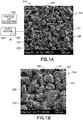
- FIG. 1A an optical micrograph at a 50X magnification level of the masticated particles 310 of the present disclosure is illustrated.
- Fig. 1B is an optical micrograph at a higher magnification level (e.g., 100X) of the masticated particles 310 of Fig. 1A , which more clearly exhibits the structural features of the masticated particles 310.
- the masticated particles 310 are particles that have been formed by grinding and/crushing a source material 360.
- the masticated particles 310 include a surface or surfaces 321 formed of at least angular facets 325 and may be referred to as faceted particles 320.
- the angular facets 325 of each faceted particle 320 may be randomly formed and may be unique from other angular facets 325 of other faceted particles 320.
- a particle size distribution 350 of the masticated particles 310 is about 40 microns to about 180 microns; while in other aspects the particle size distribution 350 of the masticated particles 310 is about 40 microns to about 75 microns. In other aspects, the masticated particles 310 may be smaller than about 40 microns or larger than about 180 microns.
- the masticated particles 310 may be formed of any suitable material including, but not limited to, titanium, steel, nickel, aluminum, or alloys of one or more of the aforementioned metals. In other aspects, the masticated particles 310 may comprise a polymer.
- the masticated particles 310 having the surface 321 with the angular facets 325 of the present disclosure may be formed by the non-limiting exemplary method 200 illustrated in Fig. 2 .
- any suitable source material 360 such as the metals, alloys, or polymer described herein, is provided ( Fig. 2 , Block 210) for producing the masticated particles 310.
- the source material 360 may be a recycled source material 361, such as recycled titanium or titanium alloy scrap material.
- the recycled source material 361 may include machined scrap, fasteners, and/or other types of scrap material. Titanium 64 (Ti64) machined scrap is a particularly advantageous recycled source material as it may be abundantly available, which may further reduce the costs associated with producing the masticated particles 310.
- the source material may be newly manufactured material 362 (i.e., not recycled).
- the source material 360 is embrittled ( Fig. 2 , Block 220) in any suitable manner so that the source material may be masticated (i.e., crushed and or ground) into the masticated particles 310.
- the source material 360 may be embrittled through, as non-limiting examples, hydrogen embrittlement, cryogenic embrittlement, hydrogen sulfide embrittlement, adsorption embrittlement, liquid metal embrittlement, metal-induced embrittlement, neutron embrittlement and combinations thereof.
- the embrittled source material 360 is masticated in any suitable manner to produce the masticated particles 310 ( Fig. 2 , Block 230).
- Masticating the source material 360 may be performed by any suitable apparatus that grinds and/or crushes the embrittled source material 360. Suitable examples of masticating apparatus include, but are not limited to, mills, grinders, shredders, other suitable devices or a combination thereof.
- the masticated particles 310 after mastication, may remain embrittled.
- the masticated particles 310 may be de-embrittled ( Fig. 2 , Block 240) by, for example, dehydriding and/or heating the embrittled masticated particles 310. De-embrittling the masticated particles 310 may relieve any stresses that have built up in the masticated particles 310 during embrittling and mastication.
- the masticated particles 310 are supplied or otherwise fed to a deposition head 132 (see, e.g., Fig. 3 ) of a direct energy deposition additive manufacturing apparatus 100 ( Fig. 2 , Block 250) as illustrated as a powder feed additive manufacturing apparatus 101 in Figs. 3 and 4 .
- the directed energy deposition additive manufacturing apparatus 100 may be configured for laser cladding, direct metal deposition, direct light fabrication, laser direct casting, laser forming, shape deposition manufacturing, laser engineer net shaping, laser powder fusion, laser-aided direct-metal deposition, laser-based multi-directional metal deposition, or laser aided manufacturing process where the masticated particles 310 are fed into or towards a directed energy source 136 (e.g., such as any suitable laser).
- a directed energy source 136 e.g., such as any suitable laser.
- the directed energy deposition additive manufacturing apparatus 100 includes a hopper 110 for storing the masticated particles 310, a deposition head 132 for depositing the masticated particles 310, and a build table 150 (which may hold a substrate 140) onto which the masticated particles 310 are deposited as a melt pool 438 (see Fig. 5 ) to form the part 160.
- the masticated particles 310 are fed or otherwise transferred from the hopper 110 to the deposition head 132 through any suitable transfer line 125 (e.g., a conduit through which the masticated particles 310 pass).
- the masticated particles 310 may be gravity fed, fed with the use of an auger, and/or be pneumatically conveyed from the hopper 110 through the transfer line 125 to the deposition head 132.
- the hopper 110 may include any suitable vibrating device 185 configured to continuously or intermittently vibrate at least side walls 112 of the hopper 110 in order to initiate flow of the masticated particles 310 from the hopper 110 to the deposition head 132.
- the vibrating device 185 may be, for example, an oscillator, a piezoelectric actuator, or any other suitable apparatus inducing movement of the masticated particles 310 within the hopper 110.
- the directed energy deposition additive manufacturing device 100 illustrated in Fig. 3 includes a frame 198 that forms an inert gas filled chamber 190 in which the deposition head 132 and in which the part 160 is produced.
- the deposition head 132 is disposed on a positioning movement system, referred to herein as gantry 170.
- the gantry 170 is controlled by any suitable programmable controller 199 for moving at least the deposition head 132 along a predetermined path in one or more of X, Y, Z directions for depositing the masticated particles 310 as the melt pool 438 ( Fig. 5 ) so as to form part 160.
- the gantry 170 includes an X axis rail 195 to which a carriage 197 is movably coupled (and carried by the X axis rail 195) for movement in the X direction.
- the deposition head 132 is coupled to the carriage 197.
- the X axis rail 195 is movably coupled to and carried by a Z axis rail 196 for movement of the deposition head 132 in the Z direction.
- the Z axis rail 196 is coupled to and carried by a Y axis rail 194 for movement of the deposition head 132 in the Y direction.
- the gantry 170 includes end supports 172 that movably couple the Y axis rail 194 to the frame 198.
- a smoothing head 134 may also be coupled to the carriage 197 for shaping and smoothing deposited material 480 (in a semi-molten state - see Fig. 5 ) deposited on the build table 150 adjacent the melt pool 438 (see Fig. 5 ).
- the build table 150 instead of being fixed in position within the inert gas filled chamber 190, may include a positioning movement system 151 that is controlled by the programmable controller 199 that moves the build table in one or more of the X, Y, Z directions. Where the build table 150 is provided with a degree of freedom of movement in one of the X, Y, Z directions the corresponding degree of freedom of movement may be removed from the gantry 170.
- the directed energy deposition additive manufacturing apparatus 100 may include any suitable number of deposition heads for depositing at least one type of direct energy feed particle 616, where each type of direct energy feed particle has a different material characteristic (e.g., shape, material, size, etc.).
- Fig. 4 illustrates an exemplary side view of the directed energy deposition additive manufacturing apparatus 100 having two deposition heads 132, 632 disposed within the inert gas filled chamber 190.
- the deposition head 132 and the build table 150 are coupled to the frame 198 in a manner substantially similar to that described above with respect to Fig. 3 .
- the deposition head 632 may be coupled to the frame 198 for movement in one or more of the X, Y, Z directions by a gantry 670 that is substantially similar to gantry 170 described above.
- the gantry 670 is controlled by any suitable programmable controller 199 for moving at least the deposition head 632 along a predetermined path in one or more of X, Y, Z directions for depositing the masticated particles 310 (or other suitable direct energy feed particle 616) as a melt pool 438 (see Fig. 5 ) so as to form part 160.
- the gantry 670 includes an X axis rail 695 to which a carriage 697 is movably coupled (and carried by the X axis rail 695) for movement in the X direction.
- a smoothing head 634 may be coupled to the carriage 697 in a manner similar to that described herein for smoothing head 134.
- the deposition head 632 is coupled to the carriage 697.
- the X axis rail 695 is movably coupled to and carried by a Z axis rail (not shown but similar to Z axis rail 196) for movement of the deposition head 632 in the Z direction.
- the Z axis rail is coupled to and carried by a Y axis rail 694 for movement of the deposition head 632 in the Y direction.
- the build table 150 may be movably coupled to the frame 198 for movement in the Y direction.
- the gantry 670 includes end supports 672 that movably couple the Y axis rail 694 to the frame 198.
- the gantry 170 and the gantry 670 may be configured in any suitable manner so that the respective deposition heads 132, 632 follow the same path (i.e., one deposition head follows the other deposition head along a common path) so as to overlay/deposit material from one deposition head 132, 632 on top of material from the other deposition head 132, 632 so as to form an in situ alloy 499 (see Figs. 4 and 5 ).
- the two deposition heads 132, 632 may provide for decreased production cycle time as well as the deposition of more than one type of direct energy feed particle 616 through the respective depositions heads 132, 632.
- one hopper 110 and transfer line 125 supplies direct energy feed particles 616, such as the masticated particles 310 to one of the deposition heads 132.
- the second hopper 614 and transfer line 625 supplies direct energy feed particles 616 to the deposition head 632.
- the direct energy feed particles 616 supplied to the deposition head 632 may have the same or different characteristics than the masticated particles 310 supplied to the deposition head 132.
- At least one of the two direct energy feed particles 616 supplied by the hoppers 110, 614 used in the directed energy deposition additive manufacturing apparatus 100 of Fig. 4 is the masticated particles 310.
- the second direct energy feed particle 616 supplied by the other hopper 110, 614 may be a conventional spherical powder having spherical particles 617.
- both hoppers 110, 614 may supply direct energy feed particles 616 in the form of masticated particles 310, wherein the masticated particles 310 provided by hopper 110 may be different in material composition and/or in mechanical properties than the masticated particles 310 provided by the hopper 614.
- the supply of different types of direct energy feed particles 616 from the two hoppers 110, 614 of Fig. 4 to the respective deposition heads 132, 632 may provide for the formation of an in situ alloy 499 (see Figs. 4 and 5 ) using the directed energy deposition additive manufacturing apparatus 100 having multiple deposition heads 132, 632.
- the deposition head 132 (noting deposition head 632 is substantially similar to deposition head 132) employs the directed energy source 136 to melt at least one direct energy feed particle stream 490 ( Figs. 5 and 6 ) ejected from a respective deposition nozzle 533 ( Figs. 5 and 6 ) of the deposition head 132.
- the directed energy source 136 melts the at least one direct energy feed particle stream 490 into the melt pool 438, which in combination with the movement of the deposition head 132 provided by the gantry 170 ( Fig. 3 ) forms a layer of material 439 that is deposited on the build table 150 or on a previously deposited layer of material 439.
- the smoothing head 134 ( Fig.
- the deposition head 132 may be located adjacent the deposition head 132 so as to remove any irregularities from or shape the layer of material 439 before the deposited material cools and solidifies. Layers of material 439 are deposited one on top of the other (e.g., the deposition head 132 or the build table 150 moves in the Y direction to facilitate stacked layers of material 439S) to form the part 160. The completed part 160 may be removed from the build table 150 in any suitable manner.
- the deposition head 132 (again noting deposition head 632 in Fig. 4 is substantially similar to deposition head 132) includes a frame 532 ( Fig. 6 ).
- the frame 532 forms an aperture 501 through which a beam 136B of the directed energy source 136 passes.
- a focusing lens 535 is disposed in the aperture 501 to focus the beam 136B of the directed energy source 136 at a focal point substantially coincident with the location of the melt pool 438.
- the frame 532 may also form one or more passages 502 through which the beam 136B of the directed energy source 136 passes where the one or more passages 502 are filled with a shield gas 580.
- the shield gas may be any inert or semi-inert gas that protects the melt pool (and the weld area of the melt pool to the underlying layers of material) from large quantities of oxygen and water vapor.
- the deposition head 132 includes one or more passages that form deposition nozzles 533 through which direct energy feed particles 316 (such as the masticated particles 310 - Fig. 3 ) pass.
- the deposition nozzles 533 are coupled to a respective hopper 110, 614 ( Figs. 3 and 4 ) by the respective transfer lines 125, 625 ( Figs. 3 and 4 ) so as to receive the direct energy feed particles 316 (such as the masticated particles 310) from the respective hopper 110, 614.
- the direct energy feed particles 316 (such as the masticated particles 310) are ejected from the respective deposition nozzles 533 as particle streams 490.
- the particles streams 490 are ejected towards the focal point of the beam 136B so that the masticated particles 310 of the particles streams 490 are melted by the directed energy source 136 to form the melt pool 438.
- a single type of masticated particles 310 flows through the deposition nozzles 533 of the deposition head 132.
- the two or more different types of direct energy feed particles 512, 513 employed in the directed energy deposition additive manufacturing apparatus 100 may vary in shape (e.g., conventional spherical powder or masticated particles 310), in chemical composition (e.g., titanium, steel, nickel or aluminum), and/or in mechanical properties.
- direct energy feed particles 512 may be masticated particles 310 formed of titanium or a titanium alloy while the direct energy feed particles 513 may be masticated particles 310 formed of aluminum.
- direct energy feed particles 512 may be the masticated particles
- the direct energy feed particles 316 may be a conventional spherical powder. Any suitable combination of materials may be provided through the respective deposition nozzles 533 to form any desired in situ alloy 499 (see Figs. 4 and 5 ).
- the resulting melt pool 438 will then be a mixture/alloy of two or more materials, which will then form an in situ alloy 499 (see Figs. 4 and 5 ) upon cooling and solidification.
- at least one of the direct energy feed particle streams 590, 591 of the present disclosure includes the masticated particles 310.
- the method 800 includes flowing the masticated particles 310 through at least one deposition nozzle 533 ( Fig. 8 , Block 810) of a directed energy deposition additive manufacturing apparatus 100, where each particle of the masticated particles 310 comprises a surface 321 formed by at least angular facets 325.
- the masticated particles 310 are stored in the hopper 110, 614 ( Figs. 3 and 4 ), which as described above is coupled to the deposition nozzle 533.
- the hopper 110, 614 is at least periodically vibrated by the vibrating device 185 ( Figs.
- more than one type of direct energy feed particles 616 are provided so as to flow through a respective deposition nozzle 533 of the directed energy deposition additive manufacturing apparatus 100 so as to form an in situ alloy 499 (see Figs. 4 and 5 ), wherein at least one of the more than one type of direct energy feed particles 616 comprises the masticated particles 310 having respective surfaces 321 formed by the at least angular facets 325.
- a first type of faceted particles 320 flows through the at least one respective deposition nozzle 533 of one deposition head 132 of a plurality of deposition heads 132, 632 ( Fig. 4 ), and a second type of faceted particles 320 flows through the at least one respective deposition nozzle 533 of another deposition head 132, 632 of the plurality of deposition heads 132, 632.
- a first type of direct energy feed particles 616 flows through a first respective deposition nozzle 533 of one deposition head 132 (and/or deposition head 632), and a second type of direct energy feed particles 616 flows through a second respective deposition nozzle 533 the one deposition head 132 (and/or deposition head 632).
- another of the more than one type of direct energy feed particles 616 comprises spherical powder.
- each of the more than one type of direct energy feed particles 616 comprises different mechanical properties.
- the faceted particles have a flowability of less than 50 seconds per 50 grams as determined by Hall flow testing in accordance with, e.g., the ASTM B213 standard.
- the masticated particles exiting the respective deposition nozzle 533 are melted ( Fig. 8 , Block 820) with a directed energy source 136 of the directed energy deposition additive manufacturing apparatus 100 so as to form the part 160.
- Hall flow testing measurements were conducted (in accordance with the ASTM B213 standard) on masticated Ti64 particles (having a size distribution of about 45 microns to about 75 microns) and spherical Ti64 powder (having a size distribution of about 45 microns to about 150 microns) to quantify the differences in flowability between masticated particles 310 and conventional spherical powder having spherical particles 617.
- the Hall flow test flowability of the feed material should be less than 50 seconds per 50 grams, or less than 45 seconds per 50 grams.
- the Hall flow test results for spherical Ti64 powder were less than 26 sec/50 grams.
- the masticated Ti64 particles may require a tap in order to initiate/induce flow, whereas the spherical Ti64 powder did not require a tap to initiate flow.
- the feed hopper 110, 614 Fig.
- the cost of the masticated Ti64 particles are about 75% to about 90% lower than the spherical Ti64 powder, which provides a tremendous cost reduction opportunity for the methods of additively manufacturing the part 160.
- solid lines, if any, connecting various elements and/or components may represent mechanical, electrical, fluid, optical, electromagnetic, wireless and other couplings and/or combinations thereof.
- "coupled” means associated directly as well as indirectly.
- a member A may be directly associated with a member B, or may be indirectly associated therewith, e.g., via another member C. It will be understood that not all relationships among the various disclosed elements are necessarily represented. Accordingly, couplings other than those depicted in the drawings may also exist.
- Dashed lines, if any, connecting blocks designating the various elements and/or components represent couplings similar in function and purpose to those represented by solid lines; however, couplings represented by the dashed lines may either be selectively provided or may relate to alternative examples of the present disclosure.
- elements and/or components, if any, represented with dashed lines indicate alternative examples of the present disclosure.
- One or more elements shown in solid and/or dashed lines may be omitted from a particular example without departing from the scope of the present disclosure.
- Environmental elements, if any, are represented with dotted lines. Virtual (imaginary) elements may also be shown for clarity.
- the blocks may represent operations and/or portions thereof and lines connecting the various blocks do not imply any particular order or dependency of the operations or portions thereof. Blocks represented by dashed lines indicate alternative operations and/or portions thereof. Dashed lines, if any, connecting the various blocks represent alternative dependencies of the operations or portions thereof. It will be understood that not all dependencies among the various disclosed operations are necessarily represented. Figs. 2 and 8 and the accompanying disclosure describing the operations of the method(s) set forth herein should not be interpreted as necessarily determining a sequence in which the operations are to be performed. Rather, although one illustrative order is indicated, it is to be understood that the sequence of the operations may be modified when appropriate. Accordingly, certain operations may be performed in a different order or substantially simultaneously. Additionally, those skilled in the art will appreciate that not all operations described need be performed.
- first, second, etc. are used herein merely as labels, and are not intended to impose ordinal, positional, or hierarchical requirements on the items to which these terms refer. Moreover, reference to, e.g., a “second” item does not require or preclude the existence of, e.g., a "first” or lower-numbered item, and/or, e.g., a "third" or higher-numbered item.
- a system, apparatus, structure, article, element, component, or hardware “configured to” perform a specified function is indeed capable of performing the specified function without any alteration, rather than merely having potential to perform the specified function after further modification.
- the system, apparatus, structure, article, element, component, or hardware “configured to” perform a specified function is specifically selected, created, implemented, utilized, programmed, and/or designed for the purpose of performing the specified function.
- "configured to” denotes existing characteristics of a system, apparatus, structure, article, element, component, or hardware which enable the system, apparatus, structure, article, element, component, or hardware to perform the specified function without further modification.
- a system, apparatus, structure, article, element, component, or hardware described as being “configured to” perform a particular function may additionally or alternatively be described as being “adapted to” and/or as being “operative to” perform that function.
- Different examples of the device(s), apparatus(es) and method(s) disclosed herein include a variety of components, features, and functionalities. It should be understood that the various examples of the device(s), apparatus(es) and method(s) disclosed herein may include any of the components, features, and functionalities of any of the other examples of the apparatus(es) and method(s) disclosed herein in any combination, and all of such possibilities are intended to be within the scope of the present disclosure.
Landscapes
- Engineering & Computer Science (AREA)
- Chemical & Material Sciences (AREA)
- Manufacturing & Machinery (AREA)
- Materials Engineering (AREA)
- Mechanical Engineering (AREA)
- Nanotechnology (AREA)
- Powder Metallurgy (AREA)
- Manufacture Of Metal Powder And Suspensions Thereof (AREA)
Applications Claiming Priority (1)
| Application Number | Priority Date | Filing Date | Title |
|---|---|---|---|
| US16/267,814 US20200246870A1 (en) | 2019-02-05 | 2019-02-05 | Methods for additive manufacturing with masticated particles |
Publications (1)
| Publication Number | Publication Date |
|---|---|
| EP3693104A1 true EP3693104A1 (fr) | 2020-08-12 |
Family
ID=68766643
Family Applications (1)
| Application Number | Title | Priority Date | Filing Date |
|---|---|---|---|
| EP19213196.9A Pending EP3693104A1 (fr) | 2019-02-05 | 2019-12-03 | Procédés de fabrication additive avec des particules mastiquées |
Country Status (6)
| Country | Link |
|---|---|
| US (1) | US20200246870A1 (fr) |
| EP (1) | EP3693104A1 (fr) |
| JP (1) | JP2020143365A (fr) |
| CN (1) | CN111515396A (fr) |
| AU (1) | AU2019283964A1 (fr) |
| BR (1) | BR102020002336A2 (fr) |
Cited By (1)
| Publication number | Priority date | Publication date | Assignee | Title |
|---|---|---|---|---|
| WO2021123921A1 (fr) * | 2019-12-20 | 2021-06-24 | Beam | Ensemble buse de dépôt d'énergie dirigée avec buse et vibrateur qui fait vibrer la buse, et appareil de dépôt d'énergie dirigée comportant un tel ensemble buse |
Families Citing this family (1)
| Publication number | Priority date | Publication date | Assignee | Title |
|---|---|---|---|---|
| EP3789512B1 (fr) * | 2019-09-09 | 2023-11-15 | Sturm Maschinen- & Anlagenbau GmbH | Installation et procédé de revêtement de pièces |
-
2019
- 2019-02-05 US US16/267,814 patent/US20200246870A1/en not_active Abandoned
- 2019-12-03 EP EP19213196.9A patent/EP3693104A1/fr active Pending
- 2019-12-20 AU AU2019283964A patent/AU2019283964A1/en active Pending
-
2020
- 2020-01-22 JP JP2020007998A patent/JP2020143365A/ja active Pending
- 2020-02-04 BR BR102020002336-5A patent/BR102020002336A2/pt not_active Application Discontinuation
- 2020-02-04 CN CN202010079814.4A patent/CN111515396A/zh active Pending
Non-Patent Citations (6)
| Title |
|---|
| FRANCISCO MEDINA ET AL: "Reducing metal alloy powder costs for use in powder bed fusion additive manufacturing: Improving the economics for production", 31 December 2013 (2013-12-31), XP055670870, ISBN: 978-1-303-71820-5, Retrieved from the Internet <URL:https://epo.summon.serialssolutions.com/2.0.0/link/0/eLvHCXMwtV1LS8QwEA4uHkQvioLKCgN6Wwprm7Zbb8u6roIn6cXT0keqFbctxOID_O_OJG1qFRY8eAllCtP2m9CZTGa-MHaWEeFKGthWIM4Tiwf2xIpdV1iZwL8lj33fF5Rwu5_xcOHfLfhtR8Dcyf7V0ihDW1Pn7B-sbZSiAK_R5jii1XH8ERD_2kpvaLaJjJUSACtBjY60sf4-qspXIo1ISvmiCBhGtVRsIY08xrAzq6UqTU5TXU6> [retrieved on 20200221] * |
| KHALID MAHMOOD ET AL: "Laser metal deposition of steel components using machining waste as build material", LASERS AND ELECTRO-OPTICS (CLEO), LASER SCIENCE TO PHOTONIC APPLICATIONS)-CLEO: 2011 - LASER SCIENCE TO PHOTONIC APPLICATIONS- 1-6 MAY 2011, BALTIMORE, MD, USA, IEEE, US, 1 May 2011 (2011-05-01), pages 1 - 2, XP031892218, ISBN: 978-1-4577-1223-4 * |
| LI WEI ET AL: "Ti6Al4V/SS316 multi-metallic structure fabricated by laser 3D printing and thermodynamic modeling prediction", THE INTERNATIONAL JOURNAL OF ADVANCED MANUFACTURING TECHNOLOGY, SPRINGER, LONDON, vol. 92, no. 9, 20 May 2017 (2017-05-20), pages 4511 - 4523, XP036324041, ISSN: 0268-3768, [retrieved on 20170520], DOI: 10.1007/S00170-017-0543-3 * |
| RENLIANG XU ET AL: "Comparison of sizing small particles using different technologies", POWDER TECHNOLOGY - ELECTROSTATIC PHENOMENA IN PARTICULATE PROCESSES, ELSEVIER, BASEL (CH), vol. 132, no. 2-3, 24 June 2003 (2003-06-24), pages 145 - 153, XP002711749, ISSN: 0032-5910, DOI: 10.1016/S0032-5910(03)00048-2 * |
| TOMASZ DUREJKO ET AL: "The Application of Globular Water-Atomized Iron Powders for Additive Manufacturing by a LENS Technique", MATERIALS, vol. 11, no. 5, 18 May 2018 (2018-05-18), pages 843, XP055670785, DOI: 10.3390/ma11050843 * |
| XUEYANG CHEN LEI YAN WEI LI ZHIYUAN WANG FRANK LIOU JOE NEWKIRK ET AL: "Effect of Powder Particle Size on the Fabrication of Ti-6Al-4V Using Direct Laser Metal Deposition from Elemental Powder Mixture", ????????:???, 10 August 2016 (2016-08-10), pages 348 - 355, XP055670854, Retrieved from the Internet <URL:https://sffsymposium.engr.utexas.edu/sites/default/files/2016/055-Chen.pdf> [retrieved on 20200221], DOI: 10.17265/2159-5275/2016.07.005 * |
Cited By (1)
| Publication number | Priority date | Publication date | Assignee | Title |
|---|---|---|---|---|
| WO2021123921A1 (fr) * | 2019-12-20 | 2021-06-24 | Beam | Ensemble buse de dépôt d'énergie dirigée avec buse et vibrateur qui fait vibrer la buse, et appareil de dépôt d'énergie dirigée comportant un tel ensemble buse |
Also Published As
| Publication number | Publication date |
|---|---|
| US20200246870A1 (en) | 2020-08-06 |
| AU2019283964A1 (en) | 2020-08-20 |
| JP2020143365A (ja) | 2020-09-10 |
| CN111515396A (zh) | 2020-08-11 |
| BR102020002336A2 (pt) | 2020-12-01 |
Similar Documents
| Publication | Publication Date | Title |
|---|---|---|
| JP6840787B2 (ja) | 鋼本体をコーティングする方法 | |
| Wang et al. | Additive manufacturing based on welding arc: a low-cost method | |
| Dietrich et al. | A new approach for a flexible powder production for additive manufacturing | |
| Zhong et al. | Experimental study of porosity reduction in high deposition-rate Laser Material Deposition | |
| Gibson et al. | Directed energy deposition processes | |
| Nouri et al. | Powder morphology in thermal spraying | |
| KR100305425B1 (ko) | 자유형3차원물품을형성하는방법및장치 | |
| JP6553514B2 (ja) | 高エネルギービームを用いた緊密性最適化済み粉末床の選択的溶融又は選択的焼結による部品の積層造形方法 | |
| KR100305343B1 (ko) | 자유형3차원물품을형성하는방법및장치 | |
| EP3693104A1 (fr) | Procédés de fabrication additive avec des particules mastiquées | |
| Gamon et al. | Microstructure and hardness comparison of as-built Inconel 625 alloy following various additive manufacturing processes | |
| MXPA03009813A (es) | Aparato y procedimiento para la deposicion y consolidacion de estado solido de particulas en polvo a alta velocidad utilizando deformacion termica de plastico. | |
| US20160339521A1 (en) | Powder improvement for additive manufacturing | |
| CN108526488A (zh) | 一种增减材制备钛合金零件的方法 | |
| US20220331858A1 (en) | SPHERICAL Ti-BASED POWDER AND MANUFACTURING METHOD THEREFOR | |
| Gibson et al. | Directed energy deposition | |
| Turichin et al. | Theory and technology of direct laser deposition | |
| CN105050756B (zh) | 丸粒的制造方法以及装置 | |
| JP2019112700A (ja) | 金属粉末材料の製造方法 | |
| Zhang et al. | Joining of copper and stainless steel 304L using direct metal deposition | |
| KR102465825B1 (ko) | 열플라즈마를 이용한 금속분말 제조장치 및 그 제조방법 | |
| Naesstroem et al. | From mine to part: directed energy deposition of iron ore | |
| Nowotny et al. | Generative manufacturing and repair of metal parts through direct laser deposition using wire material | |
| Peyre et al. | Additive manufacturing of metal alloys 1: processes, raw materials and numerical simulation | |
| Garg et al. | Evaluating gas-driven flow mechanics of non-spherical powders for directed energy deposition |
Legal Events
| Date | Code | Title | Description |
|---|---|---|---|
| PUAI | Public reference made under article 153(3) epc to a published international application that has entered the european phase |
Free format text: ORIGINAL CODE: 0009012 |
|
| STAA | Information on the status of an ep patent application or granted ep patent |
Free format text: STATUS: THE APPLICATION HAS BEEN PUBLISHED |
|
| AK | Designated contracting states |
Kind code of ref document: A1 Designated state(s): AL AT BE BG CH CY CZ DE DK EE ES FI FR GB GR HR HU IE IS IT LI LT LU LV MC MK MT NL NO PL PT RO RS SE SI SK SM TR |
|
| AX | Request for extension of the european patent |
Extension state: BA ME |
|
| STAA | Information on the status of an ep patent application or granted ep patent |
Free format text: STATUS: REQUEST FOR EXAMINATION WAS MADE |
|
| 17P | Request for examination filed |
Effective date: 20210128 |
|
| RBV | Designated contracting states (corrected) |
Designated state(s): AL AT BE BG CH CY CZ DE DK EE ES FI FR GB GR HR HU IE IS IT LI LT LU LV MC MK MT NL NO PL PT RO RS SE SI SK SM TR |
|
| STAA | Information on the status of an ep patent application or granted ep patent |
Free format text: STATUS: EXAMINATION IS IN PROGRESS |
|
| 17Q | First examination report despatched |
Effective date: 20220609 |
|
| RAP3 | Party data changed (applicant data changed or rights of an application transferred) |
Owner name: THE BOEING COMPANY |