EP3692959A1 - Ultrasonic sealing method and ultrasonic sealing device - Google Patents
Ultrasonic sealing method and ultrasonic sealing device Download PDFInfo
- Publication number
- EP3692959A1 EP3692959A1 EP17934675.4A EP17934675A EP3692959A1 EP 3692959 A1 EP3692959 A1 EP 3692959A1 EP 17934675 A EP17934675 A EP 17934675A EP 3692959 A1 EP3692959 A1 EP 3692959A1
- Authority
- EP
- European Patent Office
- Prior art keywords
- ultrasonic
- ultrasonic wave
- continuous web
- sealing
- wave generator
- Prior art date
- Legal status (The legal status is an assumption and is not a legal conclusion. Google has not performed a legal analysis and makes no representation as to the accuracy of the status listed.)
- Granted
Links
Images





Classifications
-
- B—PERFORMING OPERATIONS; TRANSPORTING
- B29—WORKING OF PLASTICS; WORKING OF SUBSTANCES IN A PLASTIC STATE IN GENERAL
- B29C—SHAPING OR JOINING OF PLASTICS; SHAPING OF MATERIAL IN A PLASTIC STATE, NOT OTHERWISE PROVIDED FOR; AFTER-TREATMENT OF THE SHAPED PRODUCTS, e.g. REPAIRING
- B29C65/00—Joining or sealing of preformed parts, e.g. welding of plastics materials; Apparatus therefor
- B29C65/02—Joining or sealing of preformed parts, e.g. welding of plastics materials; Apparatus therefor by heating, with or without pressure
- B29C65/08—Joining or sealing of preformed parts, e.g. welding of plastics materials; Apparatus therefor by heating, with or without pressure using ultrasonic vibrations
-
- A—HUMAN NECESSITIES
- A61—MEDICAL OR VETERINARY SCIENCE; HYGIENE
- A61F—FILTERS IMPLANTABLE INTO BLOOD VESSELS; PROSTHESES; DEVICES PROVIDING PATENCY TO, OR PREVENTING COLLAPSING OF, TUBULAR STRUCTURES OF THE BODY, e.g. STENTS; ORTHOPAEDIC, NURSING OR CONTRACEPTIVE DEVICES; FOMENTATION; TREATMENT OR PROTECTION OF EYES OR EARS; BANDAGES, DRESSINGS OR ABSORBENT PADS; FIRST-AID KITS
- A61F13/00—Bandages or dressings; Absorbent pads
- A61F13/15—Absorbent pads, e.g. sanitary towels, swabs or tampons for external or internal application to the body; Supporting or fastening means therefor; Tampon applicators
- A61F13/15577—Apparatus or processes for manufacturing
- A61F13/15707—Mechanical treatment, e.g. notching, twisting, compressing, shaping
- A61F13/15739—Sealing, e.g. involving cutting
-
- B—PERFORMING OPERATIONS; TRANSPORTING
- B29—WORKING OF PLASTICS; WORKING OF SUBSTANCES IN A PLASTIC STATE IN GENERAL
- B29C—SHAPING OR JOINING OF PLASTICS; SHAPING OF MATERIAL IN A PLASTIC STATE, NOT OTHERWISE PROVIDED FOR; AFTER-TREATMENT OF THE SHAPED PRODUCTS, e.g. REPAIRING
- B29C65/00—Joining or sealing of preformed parts, e.g. welding of plastics materials; Apparatus therefor
- B29C65/02—Joining or sealing of preformed parts, e.g. welding of plastics materials; Apparatus therefor by heating, with or without pressure
- B29C65/08—Joining or sealing of preformed parts, e.g. welding of plastics materials; Apparatus therefor by heating, with or without pressure using ultrasonic vibrations
- B29C65/083—Joining or sealing of preformed parts, e.g. welding of plastics materials; Apparatus therefor by heating, with or without pressure using ultrasonic vibrations using a rotary sonotrode or a rotary anvil
- B29C65/087—Joining or sealing of preformed parts, e.g. welding of plastics materials; Apparatus therefor by heating, with or without pressure using ultrasonic vibrations using a rotary sonotrode or a rotary anvil using both a rotary sonotrode and a rotary anvil
-
- B—PERFORMING OPERATIONS; TRANSPORTING
- B29—WORKING OF PLASTICS; WORKING OF SUBSTANCES IN A PLASTIC STATE IN GENERAL
- B29C—SHAPING OR JOINING OF PLASTICS; SHAPING OF MATERIAL IN A PLASTIC STATE, NOT OTHERWISE PROVIDED FOR; AFTER-TREATMENT OF THE SHAPED PRODUCTS, e.g. REPAIRING
- B29C65/00—Joining or sealing of preformed parts, e.g. welding of plastics materials; Apparatus therefor
- B29C65/78—Means for handling the parts to be joined, e.g. for making containers or hollow articles, e.g. means for handling sheets, plates, web-like materials, tubular articles, hollow articles or elements to be joined therewith; Means for discharging the joined articles from the joining apparatus
- B29C65/7858—Means for handling the parts to be joined, e.g. for making containers or hollow articles, e.g. means for handling sheets, plates, web-like materials, tubular articles, hollow articles or elements to be joined therewith; Means for discharging the joined articles from the joining apparatus characterised by the feeding movement of the parts to be joined
- B29C65/7879—Means for handling the parts to be joined, e.g. for making containers or hollow articles, e.g. means for handling sheets, plates, web-like materials, tubular articles, hollow articles or elements to be joined therewith; Means for discharging the joined articles from the joining apparatus characterised by the feeding movement of the parts to be joined said parts to be joined moving in a closed path, e.g. a rectangular path
- B29C65/7882—Means for handling the parts to be joined, e.g. for making containers or hollow articles, e.g. means for handling sheets, plates, web-like materials, tubular articles, hollow articles or elements to be joined therewith; Means for discharging the joined articles from the joining apparatus characterised by the feeding movement of the parts to be joined said parts to be joined moving in a closed path, e.g. a rectangular path said parts to be joined moving in a circular path
- B29C65/7885—Rotary turret joining machines, i.e. having several joining tools moving around an axis
-
- B—PERFORMING OPERATIONS; TRANSPORTING
- B29—WORKING OF PLASTICS; WORKING OF SUBSTANCES IN A PLASTIC STATE IN GENERAL
- B29C—SHAPING OR JOINING OF PLASTICS; SHAPING OF MATERIAL IN A PLASTIC STATE, NOT OTHERWISE PROVIDED FOR; AFTER-TREATMENT OF THE SHAPED PRODUCTS, e.g. REPAIRING
- B29C65/00—Joining or sealing of preformed parts, e.g. welding of plastics materials; Apparatus therefor
- B29C65/78—Means for handling the parts to be joined, e.g. for making containers or hollow articles, e.g. means for handling sheets, plates, web-like materials, tubular articles, hollow articles or elements to be joined therewith; Means for discharging the joined articles from the joining apparatus
- B29C65/7858—Means for handling the parts to be joined, e.g. for making containers or hollow articles, e.g. means for handling sheets, plates, web-like materials, tubular articles, hollow articles or elements to be joined therewith; Means for discharging the joined articles from the joining apparatus characterised by the feeding movement of the parts to be joined
- B29C65/7888—Means for handling of moving sheets or webs
- B29C65/7894—Means for handling of moving sheets or webs of continuously moving sheets or webs
-
- B—PERFORMING OPERATIONS; TRANSPORTING
- B29—WORKING OF PLASTICS; WORKING OF SUBSTANCES IN A PLASTIC STATE IN GENERAL
- B29C—SHAPING OR JOINING OF PLASTICS; SHAPING OF MATERIAL IN A PLASTIC STATE, NOT OTHERWISE PROVIDED FOR; AFTER-TREATMENT OF THE SHAPED PRODUCTS, e.g. REPAIRING
- B29C66/00—General aspects of processes or apparatus for joining preformed parts
- B29C66/01—General aspects dealing with the joint area or with the area to be joined
- B29C66/05—Particular design of joint configurations
- B29C66/10—Particular design of joint configurations particular design of the joint cross-sections
- B29C66/11—Joint cross-sections comprising a single joint-segment, i.e. one of the parts to be joined comprising a single joint-segment in the joint cross-section
- B29C66/112—Single lapped joints
- B29C66/1122—Single lap to lap joints, i.e. overlap joints
-
- B—PERFORMING OPERATIONS; TRANSPORTING
- B29—WORKING OF PLASTICS; WORKING OF SUBSTANCES IN A PLASTIC STATE IN GENERAL
- B29C—SHAPING OR JOINING OF PLASTICS; SHAPING OF MATERIAL IN A PLASTIC STATE, NOT OTHERWISE PROVIDED FOR; AFTER-TREATMENT OF THE SHAPED PRODUCTS, e.g. REPAIRING
- B29C66/00—General aspects of processes or apparatus for joining preformed parts
- B29C66/01—General aspects dealing with the joint area or with the area to be joined
- B29C66/05—Particular design of joint configurations
- B29C66/20—Particular design of joint configurations particular design of the joint lines, e.g. of the weld lines
- B29C66/21—Particular design of joint configurations particular design of the joint lines, e.g. of the weld lines said joint lines being formed by a single dot or dash or by several dots or dashes, i.e. spot joining or spot welding
-
- B—PERFORMING OPERATIONS; TRANSPORTING
- B29—WORKING OF PLASTICS; WORKING OF SUBSTANCES IN A PLASTIC STATE IN GENERAL
- B29C—SHAPING OR JOINING OF PLASTICS; SHAPING OF MATERIAL IN A PLASTIC STATE, NOT OTHERWISE PROVIDED FOR; AFTER-TREATMENT OF THE SHAPED PRODUCTS, e.g. REPAIRING
- B29C66/00—General aspects of processes or apparatus for joining preformed parts
- B29C66/01—General aspects dealing with the joint area or with the area to be joined
- B29C66/05—Particular design of joint configurations
- B29C66/20—Particular design of joint configurations particular design of the joint lines, e.g. of the weld lines
- B29C66/23—Particular design of joint configurations particular design of the joint lines, e.g. of the weld lines said joint lines being multiple and parallel or being in the form of tessellations
- B29C66/232—Particular design of joint configurations particular design of the joint lines, e.g. of the weld lines said joint lines being multiple and parallel or being in the form of tessellations said joint lines being multiple and parallel, i.e. the joint being formed by several parallel joint lines
-
- B—PERFORMING OPERATIONS; TRANSPORTING
- B29—WORKING OF PLASTICS; WORKING OF SUBSTANCES IN A PLASTIC STATE IN GENERAL
- B29C—SHAPING OR JOINING OF PLASTICS; SHAPING OF MATERIAL IN A PLASTIC STATE, NOT OTHERWISE PROVIDED FOR; AFTER-TREATMENT OF THE SHAPED PRODUCTS, e.g. REPAIRING
- B29C66/00—General aspects of processes or apparatus for joining preformed parts
- B29C66/01—General aspects dealing with the joint area or with the area to be joined
- B29C66/346—Making joints having variable thicknesses in the joint area, e.g. by using jaws having an adapted configuration
-
- B—PERFORMING OPERATIONS; TRANSPORTING
- B29—WORKING OF PLASTICS; WORKING OF SUBSTANCES IN A PLASTIC STATE IN GENERAL
- B29C—SHAPING OR JOINING OF PLASTICS; SHAPING OF MATERIAL IN A PLASTIC STATE, NOT OTHERWISE PROVIDED FOR; AFTER-TREATMENT OF THE SHAPED PRODUCTS, e.g. REPAIRING
- B29C66/00—General aspects of processes or apparatus for joining preformed parts
- B29C66/40—General aspects of joining substantially flat articles, e.g. plates, sheets or web-like materials; Making flat seams in tubular or hollow articles; Joining single elements to substantially flat surfaces
- B29C66/41—Joining substantially flat articles ; Making flat seams in tubular or hollow articles
- B29C66/43—Joining a relatively small portion of the surface of said articles
- B29C66/431—Joining the articles to themselves
-
- B—PERFORMING OPERATIONS; TRANSPORTING
- B29—WORKING OF PLASTICS; WORKING OF SUBSTANCES IN A PLASTIC STATE IN GENERAL
- B29C—SHAPING OR JOINING OF PLASTICS; SHAPING OF MATERIAL IN A PLASTIC STATE, NOT OTHERWISE PROVIDED FOR; AFTER-TREATMENT OF THE SHAPED PRODUCTS, e.g. REPAIRING
- B29C66/00—General aspects of processes or apparatus for joining preformed parts
- B29C66/70—General aspects of processes or apparatus for joining preformed parts characterised by the composition, physical properties or the structure of the material of the parts to be joined; Joining with non-plastics material
- B29C66/72—General aspects of processes or apparatus for joining preformed parts characterised by the composition, physical properties or the structure of the material of the parts to be joined; Joining with non-plastics material characterised by the structure of the material of the parts to be joined
- B29C66/723—General aspects of processes or apparatus for joining preformed parts characterised by the composition, physical properties or the structure of the material of the parts to be joined; Joining with non-plastics material characterised by the structure of the material of the parts to be joined being multi-layered
-
- B—PERFORMING OPERATIONS; TRANSPORTING
- B29—WORKING OF PLASTICS; WORKING OF SUBSTANCES IN A PLASTIC STATE IN GENERAL
- B29C—SHAPING OR JOINING OF PLASTICS; SHAPING OF MATERIAL IN A PLASTIC STATE, NOT OTHERWISE PROVIDED FOR; AFTER-TREATMENT OF THE SHAPED PRODUCTS, e.g. REPAIRING
- B29C66/00—General aspects of processes or apparatus for joining preformed parts
- B29C66/70—General aspects of processes or apparatus for joining preformed parts characterised by the composition, physical properties or the structure of the material of the parts to be joined; Joining with non-plastics material
- B29C66/73—General aspects of processes or apparatus for joining preformed parts characterised by the composition, physical properties or the structure of the material of the parts to be joined; Joining with non-plastics material characterised by the intensive physical properties of the material of the parts to be joined, by the optical properties of the material of the parts to be joined, by the extensive physical properties of the parts to be joined, by the state of the material of the parts to be joined or by the material of the parts to be joined being a thermoplastic or a thermoset
- B29C66/731—General aspects of processes or apparatus for joining preformed parts characterised by the composition, physical properties or the structure of the material of the parts to be joined; Joining with non-plastics material characterised by the intensive physical properties of the material of the parts to be joined, by the optical properties of the material of the parts to be joined, by the extensive physical properties of the parts to be joined, by the state of the material of the parts to be joined or by the material of the parts to be joined being a thermoplastic or a thermoset characterised by the intensive physical properties of the material of the parts to be joined
- B29C66/7318—Permeability to gases or liquids
- B29C66/73181—Permeability to gases or liquids permeable
- B29C66/73182—Permeability to gases or liquids permeable to gases
-
- B—PERFORMING OPERATIONS; TRANSPORTING
- B29—WORKING OF PLASTICS; WORKING OF SUBSTANCES IN A PLASTIC STATE IN GENERAL
- B29C—SHAPING OR JOINING OF PLASTICS; SHAPING OF MATERIAL IN A PLASTIC STATE, NOT OTHERWISE PROVIDED FOR; AFTER-TREATMENT OF THE SHAPED PRODUCTS, e.g. REPAIRING
- B29C66/00—General aspects of processes or apparatus for joining preformed parts
- B29C66/70—General aspects of processes or apparatus for joining preformed parts characterised by the composition, physical properties or the structure of the material of the parts to be joined; Joining with non-plastics material
- B29C66/73—General aspects of processes or apparatus for joining preformed parts characterised by the composition, physical properties or the structure of the material of the parts to be joined; Joining with non-plastics material characterised by the intensive physical properties of the material of the parts to be joined, by the optical properties of the material of the parts to be joined, by the extensive physical properties of the parts to be joined, by the state of the material of the parts to be joined or by the material of the parts to be joined being a thermoplastic or a thermoset
- B29C66/731—General aspects of processes or apparatus for joining preformed parts characterised by the composition, physical properties or the structure of the material of the parts to be joined; Joining with non-plastics material characterised by the intensive physical properties of the material of the parts to be joined, by the optical properties of the material of the parts to be joined, by the extensive physical properties of the parts to be joined, by the state of the material of the parts to be joined or by the material of the parts to be joined being a thermoplastic or a thermoset characterised by the intensive physical properties of the material of the parts to be joined
- B29C66/7318—Permeability to gases or liquids
- B29C66/73185—Permeability to gases or liquids non-permeable
- B29C66/73187—Permeability to gases or liquids non-permeable to liquids
-
- B—PERFORMING OPERATIONS; TRANSPORTING
- B29—WORKING OF PLASTICS; WORKING OF SUBSTANCES IN A PLASTIC STATE IN GENERAL
- B29C—SHAPING OR JOINING OF PLASTICS; SHAPING OF MATERIAL IN A PLASTIC STATE, NOT OTHERWISE PROVIDED FOR; AFTER-TREATMENT OF THE SHAPED PRODUCTS, e.g. REPAIRING
- B29C66/00—General aspects of processes or apparatus for joining preformed parts
- B29C66/70—General aspects of processes or apparatus for joining preformed parts characterised by the composition, physical properties or the structure of the material of the parts to be joined; Joining with non-plastics material
- B29C66/73—General aspects of processes or apparatus for joining preformed parts characterised by the composition, physical properties or the structure of the material of the parts to be joined; Joining with non-plastics material characterised by the intensive physical properties of the material of the parts to be joined, by the optical properties of the material of the parts to be joined, by the extensive physical properties of the parts to be joined, by the state of the material of the parts to be joined or by the material of the parts to be joined being a thermoplastic or a thermoset
- B29C66/739—General aspects of processes or apparatus for joining preformed parts characterised by the composition, physical properties or the structure of the material of the parts to be joined; Joining with non-plastics material characterised by the intensive physical properties of the material of the parts to be joined, by the optical properties of the material of the parts to be joined, by the extensive physical properties of the parts to be joined, by the state of the material of the parts to be joined or by the material of the parts to be joined being a thermoplastic or a thermoset characterised by the material of the parts to be joined being a thermoplastic or a thermoset
- B29C66/7392—General aspects of processes or apparatus for joining preformed parts characterised by the composition, physical properties or the structure of the material of the parts to be joined; Joining with non-plastics material characterised by the intensive physical properties of the material of the parts to be joined, by the optical properties of the material of the parts to be joined, by the extensive physical properties of the parts to be joined, by the state of the material of the parts to be joined or by the material of the parts to be joined being a thermoplastic or a thermoset characterised by the material of the parts to be joined being a thermoplastic or a thermoset characterised by the material of at least one of the parts being a thermoplastic
- B29C66/73921—General aspects of processes or apparatus for joining preformed parts characterised by the composition, physical properties or the structure of the material of the parts to be joined; Joining with non-plastics material characterised by the intensive physical properties of the material of the parts to be joined, by the optical properties of the material of the parts to be joined, by the extensive physical properties of the parts to be joined, by the state of the material of the parts to be joined or by the material of the parts to be joined being a thermoplastic or a thermoset characterised by the material of the parts to be joined being a thermoplastic or a thermoset characterised by the material of at least one of the parts being a thermoplastic characterised by the materials of both parts being thermoplastics
-
- B—PERFORMING OPERATIONS; TRANSPORTING
- B29—WORKING OF PLASTICS; WORKING OF SUBSTANCES IN A PLASTIC STATE IN GENERAL
- B29C—SHAPING OR JOINING OF PLASTICS; SHAPING OF MATERIAL IN A PLASTIC STATE, NOT OTHERWISE PROVIDED FOR; AFTER-TREATMENT OF THE SHAPED PRODUCTS, e.g. REPAIRING
- B29C66/00—General aspects of processes or apparatus for joining preformed parts
- B29C66/80—General aspects of machine operations or constructions and parts thereof
- B29C66/81—General aspects of the pressing elements, i.e. the elements applying pressure on the parts to be joined in the area to be joined, e.g. the welding jaws or clamps
- B29C66/814—General aspects of the pressing elements, i.e. the elements applying pressure on the parts to be joined in the area to be joined, e.g. the welding jaws or clamps characterised by the design of the pressing elements, e.g. of the welding jaws or clamps
- B29C66/8141—General aspects of the pressing elements, i.e. the elements applying pressure on the parts to be joined in the area to be joined, e.g. the welding jaws or clamps characterised by the design of the pressing elements, e.g. of the welding jaws or clamps characterised by the surface geometry of the part of the pressing elements, e.g. welding jaws or clamps, coming into contact with the parts to be joined
- B29C66/81427—General aspects of the pressing elements, i.e. the elements applying pressure on the parts to be joined in the area to be joined, e.g. the welding jaws or clamps characterised by the design of the pressing elements, e.g. of the welding jaws or clamps characterised by the surface geometry of the part of the pressing elements, e.g. welding jaws or clamps, coming into contact with the parts to be joined comprising a single ridge, e.g. for making a weakening line; comprising a single tooth
-
- B—PERFORMING OPERATIONS; TRANSPORTING
- B29—WORKING OF PLASTICS; WORKING OF SUBSTANCES IN A PLASTIC STATE IN GENERAL
- B29C—SHAPING OR JOINING OF PLASTICS; SHAPING OF MATERIAL IN A PLASTIC STATE, NOT OTHERWISE PROVIDED FOR; AFTER-TREATMENT OF THE SHAPED PRODUCTS, e.g. REPAIRING
- B29C66/00—General aspects of processes or apparatus for joining preformed parts
- B29C66/80—General aspects of machine operations or constructions and parts thereof
- B29C66/81—General aspects of the pressing elements, i.e. the elements applying pressure on the parts to be joined in the area to be joined, e.g. the welding jaws or clamps
- B29C66/814—General aspects of the pressing elements, i.e. the elements applying pressure on the parts to be joined in the area to be joined, e.g. the welding jaws or clamps characterised by the design of the pressing elements, e.g. of the welding jaws or clamps
- B29C66/8145—General aspects of the pressing elements, i.e. the elements applying pressure on the parts to be joined in the area to be joined, e.g. the welding jaws or clamps characterised by the design of the pressing elements, e.g. of the welding jaws or clamps characterised by the constructional aspects of the pressing elements, e.g. of the welding jaws or clamps
-
- B—PERFORMING OPERATIONS; TRANSPORTING
- B29—WORKING OF PLASTICS; WORKING OF SUBSTANCES IN A PLASTIC STATE IN GENERAL
- B29C—SHAPING OR JOINING OF PLASTICS; SHAPING OF MATERIAL IN A PLASTIC STATE, NOT OTHERWISE PROVIDED FOR; AFTER-TREATMENT OF THE SHAPED PRODUCTS, e.g. REPAIRING
- B29C66/00—General aspects of processes or apparatus for joining preformed parts
- B29C66/80—General aspects of machine operations or constructions and parts thereof
- B29C66/81—General aspects of the pressing elements, i.e. the elements applying pressure on the parts to be joined in the area to be joined, e.g. the welding jaws or clamps
- B29C66/814—General aspects of the pressing elements, i.e. the elements applying pressure on the parts to be joined in the area to be joined, e.g. the welding jaws or clamps characterised by the design of the pressing elements, e.g. of the welding jaws or clamps
- B29C66/8145—General aspects of the pressing elements, i.e. the elements applying pressure on the parts to be joined in the area to be joined, e.g. the welding jaws or clamps characterised by the design of the pressing elements, e.g. of the welding jaws or clamps characterised by the constructional aspects of the pressing elements, e.g. of the welding jaws or clamps
- B29C66/81455—General aspects of the pressing elements, i.e. the elements applying pressure on the parts to be joined in the area to be joined, e.g. the welding jaws or clamps characterised by the design of the pressing elements, e.g. of the welding jaws or clamps characterised by the constructional aspects of the pressing elements, e.g. of the welding jaws or clamps being a fluid inflatable bag or bladder, a diaphragm or a vacuum bag for applying isostatic pressure
-
- B—PERFORMING OPERATIONS; TRANSPORTING
- B29—WORKING OF PLASTICS; WORKING OF SUBSTANCES IN A PLASTIC STATE IN GENERAL
- B29C—SHAPING OR JOINING OF PLASTICS; SHAPING OF MATERIAL IN A PLASTIC STATE, NOT OTHERWISE PROVIDED FOR; AFTER-TREATMENT OF THE SHAPED PRODUCTS, e.g. REPAIRING
- B29C66/00—General aspects of processes or apparatus for joining preformed parts
- B29C66/80—General aspects of machine operations or constructions and parts thereof
- B29C66/81—General aspects of the pressing elements, i.e. the elements applying pressure on the parts to be joined in the area to be joined, e.g. the welding jaws or clamps
- B29C66/814—General aspects of the pressing elements, i.e. the elements applying pressure on the parts to be joined in the area to be joined, e.g. the welding jaws or clamps characterised by the design of the pressing elements, e.g. of the welding jaws or clamps
- B29C66/8145—General aspects of the pressing elements, i.e. the elements applying pressure on the parts to be joined in the area to be joined, e.g. the welding jaws or clamps characterised by the design of the pressing elements, e.g. of the welding jaws or clamps characterised by the constructional aspects of the pressing elements, e.g. of the welding jaws or clamps
- B29C66/81463—General aspects of the pressing elements, i.e. the elements applying pressure on the parts to be joined in the area to be joined, e.g. the welding jaws or clamps characterised by the design of the pressing elements, e.g. of the welding jaws or clamps characterised by the constructional aspects of the pressing elements, e.g. of the welding jaws or clamps comprising a plurality of single pressing elements, e.g. a plurality of sonotrodes, or comprising a plurality of single counter-pressing elements, e.g. a plurality of anvils, said plurality of said single elements being suitable for making a single joint
- B29C66/81465—General aspects of the pressing elements, i.e. the elements applying pressure on the parts to be joined in the area to be joined, e.g. the welding jaws or clamps characterised by the design of the pressing elements, e.g. of the welding jaws or clamps characterised by the constructional aspects of the pressing elements, e.g. of the welding jaws or clamps comprising a plurality of single pressing elements, e.g. a plurality of sonotrodes, or comprising a plurality of single counter-pressing elements, e.g. a plurality of anvils, said plurality of said single elements being suitable for making a single joint one placed behind the other in a single row in the feed direction
-
- B—PERFORMING OPERATIONS; TRANSPORTING
- B29—WORKING OF PLASTICS; WORKING OF SUBSTANCES IN A PLASTIC STATE IN GENERAL
- B29C—SHAPING OR JOINING OF PLASTICS; SHAPING OF MATERIAL IN A PLASTIC STATE, NOT OTHERWISE PROVIDED FOR; AFTER-TREATMENT OF THE SHAPED PRODUCTS, e.g. REPAIRING
- B29C66/00—General aspects of processes or apparatus for joining preformed parts
- B29C66/80—General aspects of machine operations or constructions and parts thereof
- B29C66/81—General aspects of the pressing elements, i.e. the elements applying pressure on the parts to be joined in the area to be joined, e.g. the welding jaws or clamps
- B29C66/816—General aspects of the pressing elements, i.e. the elements applying pressure on the parts to be joined in the area to be joined, e.g. the welding jaws or clamps characterised by the mounting of the pressing elements, e.g. of the welding jaws or clamps
- B29C66/8161—General aspects of the pressing elements, i.e. the elements applying pressure on the parts to be joined in the area to be joined, e.g. the welding jaws or clamps characterised by the mounting of the pressing elements, e.g. of the welding jaws or clamps said pressing elements being supported or backed-up by springs or by resilient material
- B29C66/81611—General aspects of the pressing elements, i.e. the elements applying pressure on the parts to be joined in the area to be joined, e.g. the welding jaws or clamps characterised by the mounting of the pressing elements, e.g. of the welding jaws or clamps said pressing elements being supported or backed-up by springs or by resilient material by resilient material
-
- B—PERFORMING OPERATIONS; TRANSPORTING
- B29—WORKING OF PLASTICS; WORKING OF SUBSTANCES IN A PLASTIC STATE IN GENERAL
- B29C—SHAPING OR JOINING OF PLASTICS; SHAPING OF MATERIAL IN A PLASTIC STATE, NOT OTHERWISE PROVIDED FOR; AFTER-TREATMENT OF THE SHAPED PRODUCTS, e.g. REPAIRING
- B29C66/00—General aspects of processes or apparatus for joining preformed parts
- B29C66/80—General aspects of machine operations or constructions and parts thereof
- B29C66/81—General aspects of the pressing elements, i.e. the elements applying pressure on the parts to be joined in the area to be joined, e.g. the welding jaws or clamps
- B29C66/816—General aspects of the pressing elements, i.e. the elements applying pressure on the parts to be joined in the area to be joined, e.g. the welding jaws or clamps characterised by the mounting of the pressing elements, e.g. of the welding jaws or clamps
- B29C66/8163—Self-aligning to the joining plane, e.g. mounted on a ball and socket
-
- B—PERFORMING OPERATIONS; TRANSPORTING
- B29—WORKING OF PLASTICS; WORKING OF SUBSTANCES IN A PLASTIC STATE IN GENERAL
- B29C—SHAPING OR JOINING OF PLASTICS; SHAPING OF MATERIAL IN A PLASTIC STATE, NOT OTHERWISE PROVIDED FOR; AFTER-TREATMENT OF THE SHAPED PRODUCTS, e.g. REPAIRING
- B29C66/00—General aspects of processes or apparatus for joining preformed parts
- B29C66/80—General aspects of machine operations or constructions and parts thereof
- B29C66/82—Pressure application arrangements, e.g. transmission or actuating mechanisms for joining tools or clamps
- B29C66/822—Transmission mechanisms
- B29C66/8221—Scissor or lever mechanisms, i.e. involving a pivot point
-
- B—PERFORMING OPERATIONS; TRANSPORTING
- B29—WORKING OF PLASTICS; WORKING OF SUBSTANCES IN A PLASTIC STATE IN GENERAL
- B29C—SHAPING OR JOINING OF PLASTICS; SHAPING OF MATERIAL IN A PLASTIC STATE, NOT OTHERWISE PROVIDED FOR; AFTER-TREATMENT OF THE SHAPED PRODUCTS, e.g. REPAIRING
- B29C66/00—General aspects of processes or apparatus for joining preformed parts
- B29C66/80—General aspects of machine operations or constructions and parts thereof
- B29C66/82—Pressure application arrangements, e.g. transmission or actuating mechanisms for joining tools or clamps
- B29C66/822—Transmission mechanisms
- B29C66/8226—Cam mechanisms; Wedges; Eccentric mechanisms
- B29C66/82263—Follower pin or roller cooperating with a groove
-
- B—PERFORMING OPERATIONS; TRANSPORTING
- B29—WORKING OF PLASTICS; WORKING OF SUBSTANCES IN A PLASTIC STATE IN GENERAL
- B29C—SHAPING OR JOINING OF PLASTICS; SHAPING OF MATERIAL IN A PLASTIC STATE, NOT OTHERWISE PROVIDED FOR; AFTER-TREATMENT OF THE SHAPED PRODUCTS, e.g. REPAIRING
- B29C66/00—General aspects of processes or apparatus for joining preformed parts
- B29C66/80—General aspects of machine operations or constructions and parts thereof
- B29C66/82—Pressure application arrangements, e.g. transmission or actuating mechanisms for joining tools or clamps
- B29C66/824—Actuating mechanisms
- B29C66/8242—Pneumatic or hydraulic drives
- B29C66/82421—Pneumatic or hydraulic drives using an inflatable element positioned between the joining tool and a backing-up part
-
- B—PERFORMING OPERATIONS; TRANSPORTING
- B29—WORKING OF PLASTICS; WORKING OF SUBSTANCES IN A PLASTIC STATE IN GENERAL
- B29C—SHAPING OR JOINING OF PLASTICS; SHAPING OF MATERIAL IN A PLASTIC STATE, NOT OTHERWISE PROVIDED FOR; AFTER-TREATMENT OF THE SHAPED PRODUCTS, e.g. REPAIRING
- B29C66/00—General aspects of processes or apparatus for joining preformed parts
- B29C66/80—General aspects of machine operations or constructions and parts thereof
- B29C66/83—General aspects of machine operations or constructions and parts thereof characterised by the movement of the joining or pressing tools
- B29C66/832—Reciprocating joining or pressing tools
- B29C66/8324—Joining or pressing tools pivoting around one axis
-
- B—PERFORMING OPERATIONS; TRANSPORTING
- B29—WORKING OF PLASTICS; WORKING OF SUBSTANCES IN A PLASTIC STATE IN GENERAL
- B29C—SHAPING OR JOINING OF PLASTICS; SHAPING OF MATERIAL IN A PLASTIC STATE, NOT OTHERWISE PROVIDED FOR; AFTER-TREATMENT OF THE SHAPED PRODUCTS, e.g. REPAIRING
- B29C66/00—General aspects of processes or apparatus for joining preformed parts
- B29C66/80—General aspects of machine operations or constructions and parts thereof
- B29C66/83—General aspects of machine operations or constructions and parts thereof characterised by the movement of the joining or pressing tools
- B29C66/834—General aspects of machine operations or constructions and parts thereof characterised by the movement of the joining or pressing tools moving with the parts to be joined
- B29C66/8351—Jaws mounted on rollers, cylinders, drums, bands, belts or chains; Flying jaws
- B29C66/83511—Jaws mounted on rollers, cylinders, drums, bands, belts or chains; Flying jaws jaws mounted on rollers, cylinders or drums
-
- B—PERFORMING OPERATIONS; TRANSPORTING
- B29—WORKING OF PLASTICS; WORKING OF SUBSTANCES IN A PLASTIC STATE IN GENERAL
- B29C—SHAPING OR JOINING OF PLASTICS; SHAPING OF MATERIAL IN A PLASTIC STATE, NOT OTHERWISE PROVIDED FOR; AFTER-TREATMENT OF THE SHAPED PRODUCTS, e.g. REPAIRING
- B29C66/00—General aspects of processes or apparatus for joining preformed parts
- B29C66/80—General aspects of machine operations or constructions and parts thereof
- B29C66/83—General aspects of machine operations or constructions and parts thereof characterised by the movement of the joining or pressing tools
- B29C66/834—General aspects of machine operations or constructions and parts thereof characterised by the movement of the joining or pressing tools moving with the parts to be joined
- B29C66/8351—Jaws mounted on rollers, cylinders, drums, bands, belts or chains; Flying jaws
- B29C66/83511—Jaws mounted on rollers, cylinders, drums, bands, belts or chains; Flying jaws jaws mounted on rollers, cylinders or drums
- B29C66/83517—Jaws mounted on rollers, cylinders, drums, bands, belts or chains; Flying jaws jaws mounted on rollers, cylinders or drums said rollers, cylinders or drums being hollow
-
- B—PERFORMING OPERATIONS; TRANSPORTING
- B29—WORKING OF PLASTICS; WORKING OF SUBSTANCES IN A PLASTIC STATE IN GENERAL
- B29C—SHAPING OR JOINING OF PLASTICS; SHAPING OF MATERIAL IN A PLASTIC STATE, NOT OTHERWISE PROVIDED FOR; AFTER-TREATMENT OF THE SHAPED PRODUCTS, e.g. REPAIRING
- B29C66/00—General aspects of processes or apparatus for joining preformed parts
- B29C66/80—General aspects of machine operations or constructions and parts thereof
- B29C66/87—Auxiliary operations or devices
- B29C66/872—Starting or stopping procedures
-
- B—PERFORMING OPERATIONS; TRANSPORTING
- B29—WORKING OF PLASTICS; WORKING OF SUBSTANCES IN A PLASTIC STATE IN GENERAL
- B29C—SHAPING OR JOINING OF PLASTICS; SHAPING OF MATERIAL IN A PLASTIC STATE, NOT OTHERWISE PROVIDED FOR; AFTER-TREATMENT OF THE SHAPED PRODUCTS, e.g. REPAIRING
- B29C66/00—General aspects of processes or apparatus for joining preformed parts
- B29C66/90—Measuring or controlling the joining process
- B29C66/92—Measuring or controlling the joining process by measuring or controlling the pressure, the force, the mechanical power or the displacement of the joining tools
- B29C66/924—Measuring or controlling the joining process by measuring or controlling the pressure, the force, the mechanical power or the displacement of the joining tools by controlling or regulating the pressure, the force, the mechanical power or the displacement of the joining tools
- B29C66/9241—Measuring or controlling the joining process by measuring or controlling the pressure, the force, the mechanical power or the displacement of the joining tools by controlling or regulating the pressure, the force, the mechanical power or the displacement of the joining tools by controlling or regulating the pressure, the force or the mechanical power
- B29C66/92451—Measuring or controlling the joining process by measuring or controlling the pressure, the force, the mechanical power or the displacement of the joining tools by controlling or regulating the pressure, the force, the mechanical power or the displacement of the joining tools by controlling or regulating the pressure, the force or the mechanical power using joining tools having different pressure zones or using several joining tools with different pressures
-
- B—PERFORMING OPERATIONS; TRANSPORTING
- B29—WORKING OF PLASTICS; WORKING OF SUBSTANCES IN A PLASTIC STATE IN GENERAL
- B29C—SHAPING OR JOINING OF PLASTICS; SHAPING OF MATERIAL IN A PLASTIC STATE, NOT OTHERWISE PROVIDED FOR; AFTER-TREATMENT OF THE SHAPED PRODUCTS, e.g. REPAIRING
- B29C66/00—General aspects of processes or apparatus for joining preformed parts
- B29C66/90—Measuring or controlling the joining process
- B29C66/93—Measuring or controlling the joining process by measuring or controlling the speed
- B29C66/934—Measuring or controlling the joining process by measuring or controlling the speed by controlling or regulating the speed
- B29C66/93451—Measuring or controlling the joining process by measuring or controlling the speed by controlling or regulating the speed by controlling or regulating the rotational speed, i.e. the speed of revolution
-
- B—PERFORMING OPERATIONS; TRANSPORTING
- B29—WORKING OF PLASTICS; WORKING OF SUBSTANCES IN A PLASTIC STATE IN GENERAL
- B29C—SHAPING OR JOINING OF PLASTICS; SHAPING OF MATERIAL IN A PLASTIC STATE, NOT OTHERWISE PROVIDED FOR; AFTER-TREATMENT OF THE SHAPED PRODUCTS, e.g. REPAIRING
- B29C66/00—General aspects of processes or apparatus for joining preformed parts
- B29C66/90—Measuring or controlling the joining process
- B29C66/95—Measuring or controlling the joining process by measuring or controlling specific variables not covered by groups B29C66/91 - B29C66/94
- B29C66/951—Measuring or controlling the joining process by measuring or controlling specific variables not covered by groups B29C66/91 - B29C66/94 by measuring or controlling the vibration frequency and/or the vibration amplitude of vibrating joining tools, e.g. of ultrasonic welding tools
- B29C66/9511—Measuring or controlling the joining process by measuring or controlling specific variables not covered by groups B29C66/91 - B29C66/94 by measuring or controlling the vibration frequency and/or the vibration amplitude of vibrating joining tools, e.g. of ultrasonic welding tools by measuring their vibration frequency
-
- B—PERFORMING OPERATIONS; TRANSPORTING
- B29—WORKING OF PLASTICS; WORKING OF SUBSTANCES IN A PLASTIC STATE IN GENERAL
- B29C—SHAPING OR JOINING OF PLASTICS; SHAPING OF MATERIAL IN A PLASTIC STATE, NOT OTHERWISE PROVIDED FOR; AFTER-TREATMENT OF THE SHAPED PRODUCTS, e.g. REPAIRING
- B29C66/00—General aspects of processes or apparatus for joining preformed parts
- B29C66/90—Measuring or controlling the joining process
- B29C66/95—Measuring or controlling the joining process by measuring or controlling specific variables not covered by groups B29C66/91 - B29C66/94
- B29C66/951—Measuring or controlling the joining process by measuring or controlling specific variables not covered by groups B29C66/91 - B29C66/94 by measuring or controlling the vibration frequency and/or the vibration amplitude of vibrating joining tools, e.g. of ultrasonic welding tools
- B29C66/9512—Measuring or controlling the joining process by measuring or controlling specific variables not covered by groups B29C66/91 - B29C66/94 by measuring or controlling the vibration frequency and/or the vibration amplitude of vibrating joining tools, e.g. of ultrasonic welding tools by controlling their vibration frequency
-
- B—PERFORMING OPERATIONS; TRANSPORTING
- B29—WORKING OF PLASTICS; WORKING OF SUBSTANCES IN A PLASTIC STATE IN GENERAL
- B29C—SHAPING OR JOINING OF PLASTICS; SHAPING OF MATERIAL IN A PLASTIC STATE, NOT OTHERWISE PROVIDED FOR; AFTER-TREATMENT OF THE SHAPED PRODUCTS, e.g. REPAIRING
- B29C2793/00—Shaping techniques involving a cutting or machining operation
- B29C2793/009—Shaping techniques involving a cutting or machining operation after shaping
-
- B—PERFORMING OPERATIONS; TRANSPORTING
- B29—WORKING OF PLASTICS; WORKING OF SUBSTANCES IN A PLASTIC STATE IN GENERAL
- B29C—SHAPING OR JOINING OF PLASTICS; SHAPING OF MATERIAL IN A PLASTIC STATE, NOT OTHERWISE PROVIDED FOR; AFTER-TREATMENT OF THE SHAPED PRODUCTS, e.g. REPAIRING
- B29C66/00—General aspects of processes or apparatus for joining preformed parts
- B29C66/40—General aspects of joining substantially flat articles, e.g. plates, sheets or web-like materials; Making flat seams in tubular or hollow articles; Joining single elements to substantially flat surfaces
- B29C66/41—Joining substantially flat articles ; Making flat seams in tubular or hollow articles
- B29C66/43—Joining a relatively small portion of the surface of said articles
- B29C66/433—Casing-in, i.e. enclosing an element between two sheets by an outlined seam
-
- B—PERFORMING OPERATIONS; TRANSPORTING
- B29—WORKING OF PLASTICS; WORKING OF SUBSTANCES IN A PLASTIC STATE IN GENERAL
- B29C—SHAPING OR JOINING OF PLASTICS; SHAPING OF MATERIAL IN A PLASTIC STATE, NOT OTHERWISE PROVIDED FOR; AFTER-TREATMENT OF THE SHAPED PRODUCTS, e.g. REPAIRING
- B29C66/00—General aspects of processes or apparatus for joining preformed parts
- B29C66/70—General aspects of processes or apparatus for joining preformed parts characterised by the composition, physical properties or the structure of the material of the parts to be joined; Joining with non-plastics material
- B29C66/72—General aspects of processes or apparatus for joining preformed parts characterised by the composition, physical properties or the structure of the material of the parts to be joined; Joining with non-plastics material characterised by the structure of the material of the parts to be joined
- B29C66/729—Textile or other fibrous material made from plastics
- B29C66/7294—Non woven mats, e.g. felt
-
- B—PERFORMING OPERATIONS; TRANSPORTING
- B29—WORKING OF PLASTICS; WORKING OF SUBSTANCES IN A PLASTIC STATE IN GENERAL
- B29C—SHAPING OR JOINING OF PLASTICS; SHAPING OF MATERIAL IN A PLASTIC STATE, NOT OTHERWISE PROVIDED FOR; AFTER-TREATMENT OF THE SHAPED PRODUCTS, e.g. REPAIRING
- B29C66/00—General aspects of processes or apparatus for joining preformed parts
- B29C66/80—General aspects of machine operations or constructions and parts thereof
- B29C66/81—General aspects of the pressing elements, i.e. the elements applying pressure on the parts to be joined in the area to be joined, e.g. the welding jaws or clamps
- B29C66/814—General aspects of the pressing elements, i.e. the elements applying pressure on the parts to be joined in the area to be joined, e.g. the welding jaws or clamps characterised by the design of the pressing elements, e.g. of the welding jaws or clamps
- B29C66/8145—General aspects of the pressing elements, i.e. the elements applying pressure on the parts to be joined in the area to be joined, e.g. the welding jaws or clamps characterised by the design of the pressing elements, e.g. of the welding jaws or clamps characterised by the constructional aspects of the pressing elements, e.g. of the welding jaws or clamps
- B29C66/81463—General aspects of the pressing elements, i.e. the elements applying pressure on the parts to be joined in the area to be joined, e.g. the welding jaws or clamps characterised by the design of the pressing elements, e.g. of the welding jaws or clamps characterised by the constructional aspects of the pressing elements, e.g. of the welding jaws or clamps comprising a plurality of single pressing elements, e.g. a plurality of sonotrodes, or comprising a plurality of single counter-pressing elements, e.g. a plurality of anvils, said plurality of said single elements being suitable for making a single joint
- B29C66/81469—General aspects of the pressing elements, i.e. the elements applying pressure on the parts to be joined in the area to be joined, e.g. the welding jaws or clamps characterised by the design of the pressing elements, e.g. of the welding jaws or clamps characterised by the constructional aspects of the pressing elements, e.g. of the welding jaws or clamps comprising a plurality of single pressing elements, e.g. a plurality of sonotrodes, or comprising a plurality of single counter-pressing elements, e.g. a plurality of anvils, said plurality of said single elements being suitable for making a single joint one placed next to the other in a single line transverse to the feed direction, e.g. shoulder to shoulder sonotrodes
-
- B—PERFORMING OPERATIONS; TRANSPORTING
- B29—WORKING OF PLASTICS; WORKING OF SUBSTANCES IN A PLASTIC STATE IN GENERAL
- B29C—SHAPING OR JOINING OF PLASTICS; SHAPING OF MATERIAL IN A PLASTIC STATE, NOT OTHERWISE PROVIDED FOR; AFTER-TREATMENT OF THE SHAPED PRODUCTS, e.g. REPAIRING
- B29C66/00—General aspects of processes or apparatus for joining preformed parts
- B29C66/90—Measuring or controlling the joining process
- B29C66/95—Measuring or controlling the joining process by measuring or controlling specific variables not covered by groups B29C66/91 - B29C66/94
- B29C66/951—Measuring or controlling the joining process by measuring or controlling specific variables not covered by groups B29C66/91 - B29C66/94 by measuring or controlling the vibration frequency and/or the vibration amplitude of vibrating joining tools, e.g. of ultrasonic welding tools
- B29C66/9516—Measuring or controlling the joining process by measuring or controlling specific variables not covered by groups B29C66/91 - B29C66/94 by measuring or controlling the vibration frequency and/or the vibration amplitude of vibrating joining tools, e.g. of ultrasonic welding tools by controlling their vibration amplitude
-
- B—PERFORMING OPERATIONS; TRANSPORTING
- B29—WORKING OF PLASTICS; WORKING OF SUBSTANCES IN A PLASTIC STATE IN GENERAL
- B29L—INDEXING SCHEME ASSOCIATED WITH SUBCLASS B29C, RELATING TO PARTICULAR ARTICLES
- B29L2031/00—Other particular articles
- B29L2031/48—Wearing apparel
- B29L2031/4871—Underwear
- B29L2031/4878—Diapers, napkins
Definitions
- the present invention relates to a method and a device for ultrasonic-sealing.
- the processing for forming the seal portion is repeatedly executed such that multiple seal portions are formed at intervals in the direction of transporting the continuous web.
- a frequency adjusting step is executed in order to adjust the frequency of the ultrasonic waves that the ultrasonic wave generator generates for the ultrasonic horn.
- the frequency adjusting step is performed when the device for ultrasonic-sealing is powered on (starts up).
- the ultrasonic horn generates frictional heat in the continuous web while performing the seal-portion formation processing, and therefore the ultrasonic horn stretches/contracts due to the thermal influence of the frictional heat.
- this seal-portion formation processing continues for an extended period of time, there has been a possibility that the natural frequency of the ultrasonic horn, which changes along with stretching/contracting, will greatly diverge from the ultrasonic frequency that was set by adjustment at power-on (startup).
- the present invention was achieved in light of conventional problems such as that described above, and an aspect of the present invention is to suppress the problem that the frequency generated by the ultrasonic wave generator ceases to match the natural frequency of the ultrasonic horn when seal-portion formation processing is executed.
- Amain aspect of the present invention for achieving the above-described aspect is an method for ultrasonic-sealing in which a seal portion is formed in a continuous web for an absorbent article,
- the present invention it is possible to suppress the problem that the frequency generated by the ultrasonic wave generator ceases to match the natural frequency of the ultrasonic horn when seal-portion formation processing is executed.
- the frequency adjusting step is performed at a time between when the ultrasonic wave generator ends the generation of the ultrasonic wave for the ultrasonic horn in one instance of processing for forming the seal portion and when the ultrasonic wave generator starts to generate the ultrasonic wave for the ultrasonic horn in the subsequent instance of processing for forming the seal portion by the ultrasonic horn.
- the frequency adjusting step is performed at a time between when the ultrasonic horn and the anvil unclamp the continuous web and when the ultrasonic horn and the anvil subsequently clamp the continuous web.
- the frequency adjusting step is periodically executed such that the processing for forming the seal portion is performed a predetermined number of times between when the frequency adjusting step is executed and when the frequency adjusting step is subsequently executed.
- the frequency adjusting step can be executed at an appropriate interval regardless of whether the operation mode is a high speed mode or a low speed mode.
- the frequency adjusting step can be reliably executed at a time between when the ultrasonic wave generator ends the generation of the ultrasonic wave for the ultrasonic horn in one instance of processing for forming the seal portion and when the ultrasonic wave generator starts to generate the ultrasonic wave for the ultrasonic horn in the subsequent instance of processing for forming the seal portion by the ultrasonic horn.
- the frequency adjusting step is executed each time the predetermined third angular position has been reached by the sealing unit N times (N being a natural number of 2 or more) while rotating along with rotation of the rotation member.
- the ultrasonic frequency can be adjusted at an appropriate timing.
- the ultrasonic wave generator starts to generate the ultrasonic wave, and then the ultrasonic wave generator stops generating the ultrasonic wave when an ultrasonic vibration energy has reached a predetermined amount.
- An device for ultrasonic-sealing that forms a plurality of seal portions in a continuous web that is for an absorbent article, the device for ultrasonic-sealing including:
- the above device for ultrasonic-sealing achieves operations and effects similar to those of the method for ultrasonic-sealing described above.
- the sealing device 1 is an device for forming multiple seal portions S in a continuous web 30 at intervals in the direction of transporting the continuous web 30; the continuous web 30 is a stack of absorbent article base sheets and is transported along a continuous production line of the absorbent articles.
- the continuous web 30 for an absorbent article of the present embodiment will be described by way of example of a pull-on disposable diaper.
- FIG. 2 is cross-sectional view taken along IX-IX in the lower diagram in FIG. 1 , and shows a state in which the continuous web 30 is clamped between ultrasonic horns 8 and anvils 14 and seal portions S are being formed in the continuous web 30, and
- FIG. 3 is a cross-sectional view taken along X-X in the lower diagram in FIG. 1 and FIG. 2 .
- the lower diagram in FIG. 1 shows a state in which the ultrasonic horns 8 and the anvils 14 of the sealing device 1 have formed seal portions S in the continuous web 30. After the seal portions S have been formed, the continuous web 30 is cut along cut lines C-C between adjacent seal portions S, thus producing pull-on disposable diapers, which are the absorbent article of the present embodiment. Also, the upper diagram in FIG. 1 shows a state in which the continuous web 30 has been unfolded immediately before being transported into the sealing device 1.
- a first sheet 32 is located on the underside in the diagram, and a second sheet 31 is stacked thereon.
- the first sheet 32 is wider than the second sheet 31, and on one side 30A in the upper diagram in FIG. 1 , a side edge 32a of the first sheet 32 is folded over onto the second sheet 31.
- a side edge 32b of the first sheet 32 is folded over onto the second sheet 31. This folded state is shown in FIG. 3 .
- first waist bands 35 are sandwiched between the first sheet 32 and the second sheet 31.
- second waist bands 36 are sandwiched between the first sheet 32 and the second sheet 31.
- the first waist bands 35 and the second waist bands 36 are respectively arranged parallel to each other and extend as straight lines in the direction of transporting the belt-like body.
- first leg bands 37 and second leg bands 38 are provided between the first sheet 32 and the second sheet 31.
- first leg bands 37 and the second leg bands 38 extend along the direction of transporting the belt-like body while curving in a wave-like shape.
- Leg holes 34 which form leg insertion portions in the underpants-shaped state, are formed in the regions enclosed within the first leg bands 37 and the second leg bands 38.
- the first waist bands 35, the second waist bands 36, the first leg bands 37, and the second leg bands 38 are sandwiched between the first sheet 32 and the second sheet 31 in a state of being stretched by a predetermined factor in the direction of transporting the belt-like body. Also, the first sheet 32 and the second sheet 31 are adhered to the first waist bands 35, the second waist bands 36, the first leg bands 37, and the second leg bands 38, which are sandwiched therebetween, using a hot-melt adhesive or the like.
- the first sheet 32 and the second sheet 31 are breathable while also blocking the passage of liquids, and can also be fused together through heat.
- they can be made of spunbond nonwoven fabric or meltblown nonwoven fabric formed by thermoplastic synthetic fiber, or a laminated body including layers of such nonwoven fabric.
- a configuration is possible in which either the first sheet 32 or the second sheet 31 is made of nonwoven fabric, and the other one is made of breathable plastic film.
- the first waist bands 35, the second waist bands 36, the first leg bands 37, and the second leg bands 38 are elastic stretching members made of rubber or synthetic rubber strings or bands, for example.
- a liquid-absorbent body 33 is disposed between adjacent leg holes 34 on the upper surface of the second sheet 31.
- the liquid-absorbent body 33 is hourglass-shaped or rectangular, and multiple liquid-absorbent bodies 33 are arranged at constant intervals in the direction of transporting the belt-like body.
- the liquid-absorbent body 33 includes a pulverized pulp, a mixture of a pulverized pulp and a liquid-absorbent polymer (SAP), a stacked body including layers of hydrophilic nonwoven fabric, an air-laid pulp, or the like. These absorbent materials are wrapped in a liquid-permeable top sheet. Each liquid-absorbent body 33 is adhered to the upper surface of the second sheet 31 using a hot-melt adhesive or the like.
- the top sheet is formed by spun-lace nonwoven fabric, air-through nonwoven fabric, a plastic film provided with liquid passage holes, or the like.
- the belt-like body shown in the upper diagram in FIG. 1 is folded one time onto itself at a center line 01-01 that extends in the longitudinal direction, thus obtaining the continuous web 30 shown in the lower diagram in FIG. 1 .
- the continuous web 30 is transported to the sealing device 1 in the form shown in the lower diagram in FIG. 1 .
- the first sheet 32 and the second sheet 31, which are overlaid on each other are clamped and sealed between the ultrasonic horns 8 and the anvils 14 of the sealing device 1 at locations between adjacent liquid-absorbent bodies 33.
- the continuous web 30 in intermediate portions of the continuous web 30 that are sandwiched between the ultrasonic horns 8 and the anvils 14, four sheets altogether, specifically two portions of the first sheet 32 and two portions of the second sheet 31, are overlaid on each other.
- the thickness of the continuous web 30 is the smallest in the intermediate portions.
- the waist side in addition to the four sheets, the two side edges of the first sheet 32 are folded back, and the first waist bands 35 and the second waist bands 36 are also sandwiched between the sheets, thus forming the thickest portions.
- the leg side corresponding to the leg hole 34 side, the four sheets and the first leg bands 37 and the second leg bands 38 arranged therebetween are provided, and the thickness on the leg side is higher than in the intermediate portions, but lower than on the waist side.
- the first sheet 32 and the second sheet 31 are formed from a heat-fusing material, and therefore when heat is generated therein by vibration applied by the ultrasonic horn 8, the sheets become fused together in accordance with a micro protrusion pattern that is formed on an anvil facing surface 14a of the anvil 14, thus forming seal portions S.
- the pattern of the seal portions S formed by the micro protrusion pattern is a column of thin seal lines.
- the continuous web 30 is cut along cut lines C-C located between adjacent seal portions S, thus forming pull-on disposable diapers corresponding to the absorbent article.
- the absorbent article manufactured by the sealing device 1 of the present invention may be a sanitary napkin, a panty liner, or the like.
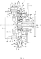
- FIG. 4 is a cross-sectional view of the sealing device 1 according to the present embodiment (a cross-section along line I-I in FIG. 9 ).
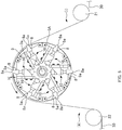
- FIG. 5 is a diagram showing a rotating drum 5 of the sealing device 1 and the internal structure thereof.
- the sealing device 1 includes a rotation-member drive portion, a rotation member (corresponding to a transporting device), sealing units 10, ultrasonic wave generators 9, swinging support members 50, and a swing drive portion.
- the rotation-member drive portion includes a rotation shaft 3a, a bearing portion 3, ball bearings 3b, a timing wheel 2, a toothed belt (not shown), and a motor (not shown).
- the bearing portion 3 is provided on a fixed table 4, which is a fixed portion, and the rotation shaft 3a is rotatably supported by the ball bearings 3b that are held in the bearing portion 3.
- the center line of the rotation shaft 3a is indicated by a rotation center line O-O.
- the timing wheel 2 which has teeth on its outer circumferential surface, is fixed to the base end portion of the rotation shaft 3a on the right side in FIG. 4 , and the toothed belt is hung around the timing wheel 2.
- a drive source that has a motor applies motive power to the timing wheel 2 via the toothed belt, the rotation shaft 3a continuously rotates in the counter-clockwise direction as seen from the left side in FIG. 4 .
- the rotation member is for transporting the continuous web 30, and includes a rotation base 6 and the rotating drum 5 as shown in FIG. 4 .
- the rotation member is fixed to the rotation shaft 3a, and rotates due to the rotation-member drive portion.
- the rotation base 6 is fixed to the rotation shaft 3a
- the rotating drum 5 is fixed to the rotation base 6, and these members rotate along with the rotation shaft 3a.
- the rotation base 6 is parallel with and opposes the fixed table 4 across a gap for ensuring space for provision of the swinging support members 50 and the swing drive portion.
- an outer circumferential surface 5A of the rotating drum 5 is provided with multiple windows 5a that are rectangular and extend parallel with the rotation center line O-O.
- the windows 5a are formed at an even pitch in the circumferential direction of the rotating drum 5, and in the present embodiment, six windows 5a are provided at an arrangement angle of 60 degrees about the rotation center line O-O.
- the sealing units 10 each include an ultrasonic horn 8, a booster 7b, a converter 7a, and an anvil 14, and are provided on the rotation member.
- the sealing units 10 rotate along with the rotation base 6 and the rotating drum 5.
- multiple (six) sealing units 10 are provided at an equiangular arrangement angle of 60 degrees along the circumferential direction of the rotation member.
- the sealing units 10 will be called a sealing unit S1, a sealing unit S2, a sealing unit S3, a sealing unit S4, a sealing unit S5, and a sealing unit S6, in order along the circumferential direction.
- the ultrasonic horn 8 is fixed to the rotation base 6 at a location inside the rotating drum 5.
- the ultrasonic horns 8 and the devices connected to the ultrasonic horns 8 are arranged in a radiating manner about the rotation center line O-O, and the arrangement angle thereof matches the arrangement angle of the windows 5a.
- the ultrasonic horns 8 each protrude outward from the corresponding window 5a of the rotating drum 5 to a projecting height h, a horn facing surface 8a at the leading end of the ultrasonic horn 8 faces outward in the normal direction (radial direction) from the rotation center line O-O, and the horn facing surface 8a is parallel with the rotation center line O-O.
- the anvils 14 are fixed to support portions 70 of holding portions 52 of the swinging support members 50, and move toward and away from the horn facing surfaces 8a as the swinging support members 50 swing. In other words, the anvils 14 each move to a position in contact with the corresponding ultrasonic horn 8, and move to a distant position rotated about 90 degrees.
- each of the swinging support members 50 is constituted by a swing portion 51 and a holding portion 52, and the swing portion 51 and the holding portion 52 are fixed.
- the anvils 14 are fixed to the support portions 70, which are provided on the holding portions 52.
- the swinging support members 50 are provided on the rotation member. Accordingly, the swinging support members 50 rotate along with the rotation base 6 and the rotating drum 5. Note that the holding portions 52 will be described in further detail later.
- FIG. 6 is an illustrative diagram for illustrating swinging operations of the swinging support members 50.
- the rotation base 6 is has a regular hexagonal front surface.
- the six swinging support members 50 are provided at intervals of 60 degrees at the center portions of the sides of the regular hexagon, and the arrangement angle of the swinging support members 50 matches the arrangement angle of the ultrasonic horns 8.
- the swing portions 51 are swingably supported to respective sides of the regular hexagon of the rotation base 6 by swing shafts 51A, and the swing shafts 51A are oriented orthogonal to the rotation center line O-O. Accordingly, the swinging support members 50 (holding portions 52) can swing the anvils 14 about the swing shafts 51A to a position radiating away from rotation center line O-O.
- a cam member 60 that constitutes the swing drive portion is fixed to the upper surface of the fixed table 4 that faces the rotation base 6.
- the cam member 60 is shaped as a flat plate that has a predetermined thickness, and as shown in FIG. 6 , the front surface is provided with a cam groove 61 that serves as a cam track.
- the cam groove 61 is continuous around the rotation center line O-O. Also, the recession depth direction of the cam groove 61 is parallel with the rotation center line O-O.
- a link mechanism is provided between the cam member 60 and each of the swing portions 51.
- drive links 53 are rotatably supported to the swing portions 51 via first coupling shafts 51B that are oriented orthogonal to the rotation center line O-O.
- Base portions 54A of rotation links 54 are rotatably supported to the rear surface of the rotation base 6 by support shafts 54a.
- the axial directions of the support shafts 54a are parallel with the rotation center line O-O.
- the leading end portions of the drive links 53 are rotatably coupled to the leading end portions of arm portions 54B of the rotation links 54 via second coupling shafts 55.
- the axial directions of the second coupling shafts 55 are parallel with the rotation center line O-O.
- a drive member 56 is attached to each of the rotation links 54.
- the drive member 56 has a drive support body 56a that is non-rotatably fixed to an intermediate portion of the rotation link 54, and a follower 56b that is provided on the drive support body 56a.
- the follower 56b can move inside the cam groove 61.
- the follower 56b rolls inside the cam groove 61, or slides therein without rolling.
- FIG. 6 shows the relative positional relationship that the rotation links 54 and the followers 56b have with the drive links 53, and the drive support bodies 56a are not shown.
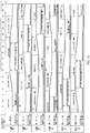
- the swinging support members 50 rotate due to the cam groove 61, and as a sealing unit 10 moves from an angular position A2 to an angular position A3 shown in FIG. 6 , the swinging support member 50 rotates toward the outer circumferential surface 5A of the rotating drum 5 and then reaches a contact position, as shown by the sealing unit 10 at the top in FIG. 4 . Also, as the sealing unit 10 moves from an angular position A0 to an angular position A1 shown in FIG. 6 , the swinging support member 50 rotates by about 90 degrees toward the fixed table 4 to a retracted position (see FIG. 9 ), as shown by the sealing unit 10 at the bottom in FIG. 4 .
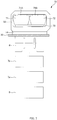
- FIG. 7 is a schematic view of a state in which one of the sealing units 10 is clamping the continuous web 30.
- the transported continuous web 30 is clamped between the ultrasonic horn 8 and the anvil 14, an ultrasonic signal emitted (generated) by the ultrasonic wave generator 9 is converted into mechanical ultrasonic vibration by the converter 7a, and the ultrasonic horn 8 receives the mechanical ultrasonic vibration via the booster 7b.
- the ultrasonic horn 8 vibrates upon receiving the mechanical ultrasonic vibration, and a seal portion S is thus formed in the continuous web 30.
- each sealing unit 10 has one ultrasonic horn 8, one booster 7b, one converter 7a, and one anvil 14, and is connected to one ultrasonic wave generator 9.
- the ultrasonic wave generators 9 are provided outside of the rotation member and are connected thereto via a slip ring (not shown) .
- first members which are either the ultrasonic horns 8 or the anvils 14 (in the present embodiment, the ultrasonic horns 8), are provided on the outer circumferential surface 5A of the rotation member (rotating drum 5), and second members, which are the other ones (in the present embodiment, the anvils 14), are provided on the opposite side of the continuous web 30 so as to be able to move toward and away from the first members (ultrasonic horns 8).
- the ultrasonic wave generator 9 is a device that emits ultrasonic waves (an ultrasound electrical signal) .
- the frequency of the ultrasonic waves emitted by the ultrasonic wave generator 9 (hereinafter, also called the ultrasonic frequency) is equivalent to the natural frequency of the ultrasonic horn 8 (i.e., the resonance frequency, which in stricter terms is the natural frequency of the ultrasonic stack including the converter 7a and the booster 7b as well, but will be described here as the natural frequency of the ultrasonic horn 8) .
- the size (length) of the ultrasonic horn 8 is designed such that the ultrasonic frequency emitted by the ultrasonic wave generator 9 (in the present embodiment, 20kHz) is equivalent to the natural frequency of the ultrasonic horn 8.
- the converter 7a is connected to the ultrasonic wave generator 9, and converts the ultrasound electrical signal emitted by the ultrasonic wave generator 9 into mechanical vibration.
- the converter 7a is provided with a piezoelectric element, and the aforementioned conversion is performed by the piezoelectric element.
- the booster 7b is connected to the converter 7a, and amplifies the vibration received from the converter 7a.
- the ultrasonic horn 8 is connected to the booster 7b. And, the ultrasonic horn 8 generates frictional heat at the interface between overlaid base materials in the continuous web 30 by vibrating due to receiving ultrasonic waves emitted by the ultrasonic wave generator 9 (ultrasonic waves in the form of mechanical vibration due to the conversion into mechanical vibration performed by the converter 7a), that is to say by applying mechanical energy from vibration to the continuous web 30. Accordingly, the base materials melt and form a seal portion S in the continuous web 30.
- the anvil 14 is a member for performing sealing by clamping the continuous web 30 together with the ultrasonic horn 8.
- the surface of the anvil 14 is provided with projection portions 14B (see FIG. 8 ), and the surfaces of the projection portions 14b make up the anvil facing surface 14a that faces the ultrasonic horn 8.
- the anvil facing surface 14a is a patterned surface set with a pattern corresponding to the seal that is to be formed in the continuous web 30.
- the anvil 14 is fixed to a support portion 70, which is provided inside the holding portion 52, so that the patterned surface faces outward from the holding portion 52, and the support portion 70 supports a first elastic member 71 and a second elastic member 72 that will be described later.
- the size (length) of the ultrasonic horn 8 can change due to wear over time and/or expansion or contraction in temperature. If the length of the ultrasonic horn 8 changes, its natural frequency will also change. If the natural frequency changes, a problem occurs in which the ultrasonic frequency emitted by the ultrasonic wave generator 9 no longer matches the natural frequency, and this can cause a problem such as a seal failure in the continuous web 30 (The details will be described later).
- the ultrasonic wave generator 9 has, as a standard function, a frequency adjusting (tuning) function for adjusting the frequency of the ultrasonic waves that the ultrasonic wave generator 9 applies to the ultrasonic horn 8.
- a frequency adjusting (tuning) function for adjusting the frequency of the ultrasonic waves that the ultrasonic wave generator 9 applies to the ultrasonic horn 8.
- the ultrasonic wave generator 9 actually emits ultrasonic waves for frequency adjustment, and detects the ultrasonic frequency that corresponds to the natural frequency of the ultrasonic horn 8.
- the detected ultrasonic frequency is used when seal-portion formation processing is subsequently performed by the ultrasonic horn 8.
- the adjusted (detected) frequency is temporarily stored in a storage unit such as a memory provided in the ultrasonic wave generator 9.
- a storage unit such as a memory provided in the ultrasonic wave generator 9.
- the ultrasonic wave generator 9 starts to emit ultrasonic waves in accordance with the ultrasonic frequency.
- the ultrasonic wave generator 9 of the present embodiment has, as a standard function and as a different function from the tuning function, a function that is for, when executing seal-portion formation processing, forming a seal portion S while adjusting the ultrasonic frequency in accordance with change thereof, the change being caused by vibration with the continuous web 30 being clamped by the ultrasonic horn 8 and the anvil 14.
- the natural frequency can change from time to time, and the ultrasonic wave generator 9 changes the ultrasonic frequency while tracking such change in the natural frequency.
- the ultrasonic frequency acquired by the frequency adjusting function is only used when starting to emit ultrasonic waves.
- the amplitude of the ultrasonic waves emitted by the ultrasonic wave generator 9 in frequency adjustment is smaller than the amplitude of the ultrasonic waves emitted by the ultrasonic wave generator 9 when forming the seal portion S.
- the ultrasonic waves emitted by the ultrasonic wave generator 9 in frequency adjustment do not need an amplitude sufficient for melting the continuous web 30, and it is sufficient to be able to detect the ultrasonic frequency that corresponds to the natural frequency of the ultrasonic horn 8.
- the amplitude of the ultrasonic waves emitted by the ultrasonic wave generator 9 in frequency adjustment is about 5% of the amplitude of the ultrasonic waves emitted by the ultrasonic wave generator 9 when forming the seal portion S. This therefore enables suppressing the amount of power that is consumed when the ultrasonic wave generator 9 performs frequency adjustment.
- FIG. 8 is an enlarged view of the internal structure of one holding portion 52.
- the holding portion 52 includes the first elastic member 71 and the second elastic member 72, and the anvil 14 is fixed to the support portion 70 that supports the first elastic member 71 and the second elastic member 72.
- the first elastic member 71 and the second elastic member 72 are arranged side-by-side in the width direction of the rotating drum 5, that is to say in a direction along the rotation center line O-O.
- the holding portion 52 swings due to the swing drive portion so as to move the anvil 14 toward or away from the ultrasonic horn 8.
- the anvil 14 and the ultrasonic horn 8 clamp the continuous web 30 when the holding portion 52 is at a contact position at which the anvil 14 and the ultrasonic horn 8 are in contact with each other.
- the first elastic member 71 and the second elastic member 72 are each an air damper or an air spring that includes a bag body (casing) that is flexibly deformable and elastically deformable and made of an elastically deformable material such as rubber or rubber embedded with a reinforcing material.
- the hollow portion of the bag body receives a supply of air as a fluid such that the interior is set to a predetermined pressure.
- the attachment sides of the first elastic member 71 and the second elastic member 72 are fixed to an attachment surface 52B of the holding portion 52 via a first fixing plate 71A and a second fixing plate 71B.
- the support portion 70 is fixed to the pressure application sides of the first elastic member 71 and the second elastic member 72, and the anvil 14 is fixed to the support portion 70.
- the support portion 70 is pressed against an inward surface 52c of a frame portion 52a due to the fluid pressure in the first elastic member 71 and the second elastic member 72.
- the first fixing plate 71A and the second fixing plate 71B are respectively provided with a first nozzle 73 and a second nozzle 74, and the first nozzle 73 and the second nozzle 74 are respectively connected to a first air pipe 75 and a second air pipe 76.
- the first elastic member 71 and the second elastic member 72 each have an air supply portion, and the internal pressures thereof can be set individually.
- the continuous web 30 of the present embodiment is the above-described continuous body of pull-on disposable diapers, and as shown in FIG. 3 , the continuous web 30 is not flat in the portions where the seal portions S are formed by the ultrasonic horns 8 and the anvils 14. In other words, the thickness is highest on the waist side, the thickness is lower in the intermediate portion, and the thickness is then higher on the leg side. Accordingly, the continuous web 30 that is to be subjected to sealing has different thicknesses in different portions, and the surface has an uneven shape.
- the anvil facing surface 14a can flexibly accommodate changes in the thickness of the continuous web 30 because the anvil 14 is pressed against the ultrasonic horn 8 by the air dampers that are bag-shaped elastic bodies filled with air (a fluid).
- the ultrasonic horn 8 and the anvil 14 can substantially evenly press the locations where the seal portions S are to be formed in the continuous web 30. Accordingly, the seal quality can be made uniform for the seal portion S locations.
- the pressure inside the bag bodies of the first elastic member 71 and the second elastic member 72 can be controlled by the supply of air from the first nozzle 73 and the second nozzle 74. Accordingly, control for changing the pressure inside the bag bodies can be easily performed in accordance with the material and the structure of the continuous web 30 that is to be subjected to sealing. For this reason, even if the structure of the continuous web 30 is changed, and the sealing pattern of the anvil facing surface 14a is accordingly changed, simply changing the pressure inside the bag bodies makes it possible to complete the setting for that stage, and to always perform sealing with optimal conditions.
- FIG. 9 is an illustrative view of operation states of the sealing device 1.
- FIG. 10 will be described later.
- the continuous web 30 is wound on a supply transporting roll 21 and transported to the outer circumferential surface 5A of the rotating drum 5.
- the continuous web 30 is wound on the outer circumferential surface 5A of the rotating drum 5 (more specifically, the horn facing surfaces 8a of the ultrasonic horns 8 that project from the outer circumferential surface 5A) over an angle of about 150 degrees, and then separates from the rotating drum 5 in a discharge section (ii), is wound around a discharge transporting roll 22, and is drawn to the outside.
- the continuous web 30 is continuously fed to the supply section (i) at a constant speed, and in the sealing device 1, rotation motive power is transmitted to the timing wheel 2, and the rotation shaft 3a as well as the rotating drum 5 and the rotation base 6 (which constitute the rotation member) rotate at a constant angular speed in the counter-clockwise direction in FIGS. 5 and 9 .
- the continuous web 30 comes into contact with the horn facing surfaces 8a of the ultrasonic horns 8 that project from the outer circumferential surface 5A of the rotating drum 5, and the rotating drum 5 rotates in this state.
- the angular speed of the rotation member is set such that the rotation circumferential speed of the horn facing surfaces 8a matches the supply speed of the continuous web 30. Accordingly, on the outer circumferential surface 5A of the rotating drum 5, the horn facing surfaces 8a of the ultrasonic horns 8 and the continuous web 30 move together without sliding relative to each other. In this way, the continuous web 30 is transported due to rotation of the rotation member (rotating drum 5) while the continuous web 30 is wound on the outer circumferential surface 5A of the rotation member (rotating drum 5).
- the circumferential arrangement pitch of the ultrasonic horns 8 that project from the outer circumferential surface 5A of the rotating drum 5 matches the arrangement pitch of the liquid-absorbent bodies 33 and the arrangement pitch of the leg holes 34 in the continuous web 30 shown in the lower diagram in FIG. 1 . Accordingly, when the continuous web 30 is transported to the outer circumferential surface 5A of the rotating drum 5, as shown in FIG. 2 , each liquid-absorbent body 33 is located between a pair of adjacent ultrasonic horns 8, and portions not including the liquid-absorbent body 33 are arranged on the horn facing surfaces 8a of the ultrasonic horns 8.
- each sealing unit 10 (the anvil 14 and the ultrasonic horn 8) moves from the predetermined angular position A0 to the predetermined angular position A1 due to the rotation of the rotation base 6, the corresponding follower 56b moves toward the rotation center line O-O due to the cam groove 61. Accordingly, at this time, as shown by the sealing unit 10 at the bottom in FIG. 4 , the corresponding swinging support member 50 rotates about the swing shaft 51A so as to face outward in the radiating direction, and the anvil 14 held by the swinging support member 50 faces outward at an angle of about 90 degrees relative to the rotation center line O-O.
- the sealing unit 10 moves from the angular position A1 to the predetermined angular position A2 (corresponding to a predetermined first angular position)
- the follower 56b is guided by the cam groove 61 so as to move circumferentially outward. Accordingly, the swinging support member 50 rotates toward the outer circumferential surface 5A of the rotating drum 5, and when the angular position A2 is reached, the anvil 14 and the ultrasonic horn 8 clamp the continuous web 30 (the anvil 14 comes into contact with the ultrasonic horn 8, and clamps the continuous web 30).
- the stacked body which includes the first sheet 32, the second sheet 31, the first waist bands 35, the second waist bands 36, the first leg bands 37, and the second leg bands 38, is compressed between the horn facing surface 8a of the ultrasonic horn 8 and the anvil facing surface 14a of the anvil 14.
- the sealing unit 10 (the anvil 14 and the ultrasonic horn 8) reaches a predetermined angular position C1 that is along the path from the angular position A1 to the angular position A2, the ultrasonic horn 8 moves from a separated state of being separated from the continuous web 30 to a contact state of being in contact with the continuous web 30.
- the processing for forming the seal portions S is processing in which the ultrasonic horn 8 and the anvil 14 clamp the continuous web 30, the seal portions S are formed in the continuous web 30 by vibration of the ultrasonic horn 8 due to receiving ultrasonic waves emitted by the ultrasonic wave generator 9, and then the continuous web 30 is unclamped.
- This ultrasonic-sealing processing is executed in the period of time from the angular position A2 to the angular position A3.
- the ultrasonic wave generator 9 starts to emit ultrasonic waves for the ultrasonic horn 8.
- the angular position of the sealing unit 10 can be detected by an encoder, and an electrical signal is used to notify the ultrasonic wave generator 9 that the sealing unit 10 (the anvil 14 and the ultrasonic horn 8) has reached the angular position B1.
- the ultrasonic horn 8 vibrates upon receiving ultrasonic waves from the ultrasonic wave generator 9, and forms a seal portion S in the continuous web 30.
- the ultrasonic wave generator 9 After the ultrasonic wave generator 9 starts to emit ultrasonic waves, when the ultrasonic vibration energy (which corresponds to the electric energy of the ultrasonic wave generator 9) reaches a predetermined amount, the ultrasonic wave generator 9 stops the ultrasonic waves (stops generating ultrasonic waves) .
- the predetermined amount is determined in advance in consideration of appropriate formation of the seal portion S. Also, the predetermined amount is determined such that the generation of ultrasonic waves is stopped before the sealing unit 10 (the anvil 14 and the ultrasonic horn 8) reaches the angular position A3 (in the present embodiment, as shown in FIG. 9 , the ultrasonic wave generator 9 stops generating ultrasonic waves at the angular position B2).
- the sealing unit 10 (the anvil 14 and the ultrasonic horn 8) reaches the angular position A3, the anvil 14 and the ultrasonic horn 8 unclamp the continuous web 30 (the anvil 14 moves away from the ultrasonic horn 8, thus unclamping the continuous web). Then, as the sealing unit 10 (the anvil 14 and the ultrasonic horn 8) moves from the angular position A3 to the angular position A0, the follower 56b is guided toward the rotation center line O-O by the cam groove 61, and the anvil 14 rotates away from the ultrasonic horn 8 and the continuous web 30.
- the angular position A0 is reached, as shown by the sealing unit 10 at the bottom in FIG. 4 again, the anvil 14 rotates to a retracted position that is at an angle of about 90 degrees relative to the rotation center line O-O.
- the sealing unit 10 (the anvil 14 and the ultrasonic horn 8) reaches a predetermined angular position C2 that is along the path from the angular position A3 to the angular position A0, the ultrasonic horn 8 moves from a contact state of being in contact with the continuous web 30 to a separated state of being separated from the continuous web 30.
- the continuous web 30 is transported out of the sealing device 1 by the discharge transporting roll 22, and is cut at the cut lines C-C shown in the lower diagram in FIG. 1 , thus producing individual pull-on disposable diapers.
- the ultrasonic wave generator 9 is provided with a frequency adjusting (tuning) function, and this frequency adjustment is executed during the operation of the sealing device 1.
- the timing of execution of the frequency adjustment is indicated by an angular position BT in FIG. 9 .
- the frequency of the ultrasonic waves that the ultrasonic wave generator 9 generates for the ultrasonic horn 8 is adjusted (a frequency adjusting step is performed) at a time that is between when the ultrasonic wave generator 9 ends the generation of ultrasonic waves for the ultrasonic horn 8 (see the angular position B2 in FIG. 9 ) in one instance of processing for forming the seal portions S and when the ultrasonic wave generator 9 starts to generate ultrasonic waves for the ultrasonic horn 8 (see the angular position B1 in FIG. 9 ) in the next instance of processing for forming the seal portions S by the ultrasonic horn 8.
- the ultrasonic wave generator 9 ends the generation of ultrasonic waves for the ultrasonic horn 8 (see the angular position B2 in FIG. 9 ), and thereafter the ultrasonic horn 8 and the anvil 14 unclamp the continuous web 30 (see the angular position A3 in FIG. 9 ). Then in the next instance of processing for forming the seal portions S by the ultrasonic horn 8, the ultrasonic horn 8 and the anvil 14 clamp the continuous web 30 (see the angular position A2 in FIG. 9 ), and then the ultrasonic wave generator 9 starts to generate ultrasonic waves for the ultrasonic horn 8 (see the angular position B1 in FIG. 9 ).
- the frequency adjusting step is executed between when the ultrasonic horn 8 and the anvil 14 unclamp the continuous web 30 (see the angular position A3 in FIG. 9 ) and when the ultrasonic horn 8 and the anvil 14 subsequently clamp the continuous web 30 (see the angular position A2 in FIG. 9 ).
- the ultrasonic horn 8 moves from a contact state of being in contact with the continuous web 30 to a separated state of being separated from the continuous web 30 (see the angular position C2 in FIG. 9 ). Then the ultrasonic horn 8 returns from the separated state to the contact state (see the angular position C1 in FIG. 9 ), and thereafter the ultrasonic horn 8 and the anvil 14 subsequently clamp the continuous web 30 (see the angular position A2 in FIG. 9 ).
- the frequency adjusting step is executed between when the ultrasonic horn 8 moves to the separated state (see the angular position C2 in FIG. 9 ) and when the ultrasonic horn 8 returns to the contact state (see the angular position C1 in FIG. 9 ).
- a frequency adjusting step is executed when the sealing unit 10 (the anvil 14 and the ultrasonic horn 8) rotates along with rotation of the rotation member and reaches the predetermined angular position BT (corresponding to a predetermined third angular position) that is along the path from the angular position A3 to the angular position A2, a frequency adjusting step is executed.
- the frequency adjusting step is executed when the ultrasonic horn 8 and the anvil 14 reach a predetermined angular position.
- an electrical signal is used to notify the ultrasonic wave generator 9 that the sealing unit 10 (the anvil 14 and the ultrasonic horn 8) has reached the angular position BT, and upon receiving that notification, the ultrasonic wave generator 9 adjusts the frequency of the ultrasonic waves that are to be emitted for the ultrasonic horn 8.
- the frequency adjusting step is executed each time the angular position BT has been reached by the sealing unit 10 N times (N being a natural number of 2 or more) while rotating along with rotation of the rotation member.
- N being a natural number of 2 or more
- FIG. 10 is an illustrative diagram for illustrating operations of the six sealing units 10.
- the six sealing units 10 all perform the previously described operations. In other words, when the sealing units 10 reach the previously described angular positions A0, A1, A2, A3, B1, and B2, they perform the previously described operations that correspond to those angular positions (note that as previously described, the generation of ultrasonic waves is stopped when the ultrasonic vibration energy reaches the predetermined amount, and therefore the ultrasonic waves do not necessarily stop when the angular position B2 is reached. However, in the present embodiment, for the sake of convenience, the following description is based on the presumption that the ultrasonic waves have stopped at the angular position B2 for all of the six sealing units 10).
- the six sealing units 10 are provided at equal intervals corresponding to an arrangement angle of 60 degrees along the circumferential direction of the rotation member that rotates, and therefore there is a time difference between when the sealing units 10 reach each of the angular positions. Accordingly, there is also a difference between the operation timings of the operations of the sealing units 10.
- the top section in FIG. 10 shows rotation positions of the rotation member (the rotation base 6 and the rotating drum 5).
- the rotation positions of the rotation member are considered to be the same as the angular positions of the sealing unit S1, which is one of the six sealing unit 10.
- the sealing unit S1 is also located at the 0 degree angular position.
- each sealing unit 10 operates in the sequence of: frequency adjustment (note: once every 50 times) ⁇ angular position BT> ⁇ start of movement for clamping ⁇ angular position A1> ⁇ clamping ⁇ angular position A2> ⁇ ultrasonic wave generation ⁇ angular position B1> ⁇ stop of ultrasonic waves ⁇ angular position B2> ⁇ unclamping (start of movement for retraction) ⁇ angular position A3> ⁇ retraction ⁇ angular position A0> ⁇ and so on; and as shown in the row for "sealing unit S1", these operations are respectively executed when the rotation position of the rotation member reaches about 20 degrees, about 70 degrees, about 130 degrees, about 140 degrees, about 230 degrees, about 250 degrees, and about 320 degrees.
- the sealing unit S1 is also located at the angular positions of about 20 degrees, about 70 degrees, about 130 degrees, about 140 degrees, about 230 degrees, about 250 degrees, and about 320 degrees when performing the aforementioned operations.
- the sealing unit S2 is the sealing unit 10 that is adjacent to the sealing unit S1 in the circumferential direction, and is separated by an angle of 60 degrees from the sealing unit S1. Accordingly, the sealing unit S2 performs the same operations as the sealing unit S1, at a delay of 60 degrees from the sealing unit S1. Accordingly, the operation graph in the row for "sealing unit S2" corresponds to a 60-degree shift rightward from the operation graph in the row for "sealing unit S1", and the above-described operations are executed when the rotation position of the rotation member reaches angles obtained by adding 60 degrees to the angles for the sealing unit S1, that is to say about 80 degrees, about 130 degrees, about 190 degrees, about 200 degrees, about 290 degrees, about 310 degrees, and about 20 degrees.
- the sealing unit S2 is also located at the angular positions of about 20 degrees, about 70 degrees, about 130 degrees, about 140 degrees, about 230 degrees, about 250 degrees, and about 320 degrees, and this is similar to the case of the sealing unit S1 (i.e., the rotation positions of the rotation member are different for the operations, but the angular positions of the sealing unit 10 are the same for the operations).
- the sealing unit S3 is the sealing unit 10 that is adjacent to the sealing unit S2 in the circumferential direction
- the sealing unit S4 is the sealing unit 10 that is adjacent to the sealing unit S3 in the circumferential direction
- the sealing unit S5 is the sealing unit 10 that is adjacent to the sealing unit S4 in the circumferential direction
- the sealing unit S6 is the sealing unit 10 that is adjacent to the sealing unit S5 in the circumferential direction. Accordingly, the sealing units S3 to S6 perform the same operations as the sealing unit S1 at angles that are respectively delayed by 120 degrees, 180 degrees, 240 degrees, and 300 degrees from the sealing unit S1.
- the operation graphs in the rows for "sealing unit S3", “sealing unit S4", “sealing unit S5", and “sealing unit S6” are respectively shifted 120 degrees, 180 degrees, 240 degrees, and 300 degrees rightward from the operation graph in the row for "sealing unit S1".
- the sealing units S3 to S6 are likewise configured such that the above-described operations performed by the sealing unit 10 upon reaching the angular positions of about 70 degrees, about 130 degrees, about 140 degrees, about 230 degrees, about 250 degrees, and about 320 degrees.
- sealing-portion forming step In other words, the formation of seal portions S with intervals therebetween is sequentially executed as the sealing units 10 each rotate along with rotation of the rotation member.
- the frequency adjusting step for adjusting the frequency of the ultrasonic waves that the ultrasonic wave generator 9 generates for the ultrasonic horn 8 is executed at a time that is between when the ultrasonic wave generator 9 ends the generation of ultrasonic waves for the ultrasonic horn 8 (the angular position B2) in one instance of processing for forming the seal portions S, and when the ultrasonic wave generator 9 starts to generate ultrasonic waves for the ultrasonic horn 8 in the next instance of processing for forming the seal portions S by the ultrasonic horn 8 (the angular position B1).
- the frequency of the ultrasonic waves that the ultrasonic wave generator 9 generates for the ultrasonic horn 8 is adjusted between when the ultrasonic horn 8 and the anvil 14 unclamp the continuous web 30 (the angular position A3) and when the ultrasonic horn 8 and the anvil 14 subsequently clamp the continuous web 30 (the angular position A2). For this reason, it is possible to suppress the problem that the frequency generated by the ultrasonic wave generator 9 ceases to match the natural frequency of the ultrasonic horn 8 when the processing for forming the seal portions S is executed (i.e., it is possible to make the two frequencies match as much as possible).
- the frequency adjusting step is performed when the sealing device 1 is powered on (starts up).
- the ultrasonic horn 8 generates frictional heat in the continuous web 30 while performing the seal-portion formation processing, and therefore the ultrasonic horn 8 stretches/contracts due to the thermal influence of the frictional heat.
- this seal-portion formation processing continues for an extended period of time, there has been a possibility that the natural frequency of the ultrasonic horn 8, which changes along with stretching/contracting, will greatly diverge from the ultrasonic frequency that was set by adjustment at power-on (startup).
- the ultrasonic wave generator 9 changes the ultrasonic frequency so as to match the natural frequency before starting to generate ultrasonic waves in the seal-portion formation processing.
- the ultrasonic wave generator 9 consumes energy (electric energy) when performing such processing. For this reason, consider the case where, as in the present embodiment, the ultrasonic wave generator 9 starts to generate ultrasonic waves when executing seal-portion formation processing, and then stops generating ultrasonic waves when the ultrasonic vibration energy (electric energy) reaches a predetermined amount, for example.
- the amount of energy consumed by the ultrasonic wave generator 9 for adjusting the ultrasonic frequency cannot be used as energy for seal portion formation, and therefore ultrasonic wave generation will stop even though seal portion formation is incomplete. Accordingly, a sealing defect will occur in the continuous web 30.
- the frequency adjusting step is executed at a time that is between when the ultrasonic wave generator 9 ends the generation of ultrasonic waves for the ultrasonic horn 8 in one instance of processing for forming the seal portions S, and when the ultrasonic wave generator 9 starts to generate ultrasonic waves for the ultrasonic horn 8 in the next instance of processing for forming the seal portions S by the ultrasonic horn 8 (more specifically, between when the ultrasonic horn 8 and the anvil 14 unclamp the continuous web 30 until when the ultrasonic horn 8 and the anvil 14 subsequently clamp the continuous web 30).
- the frequency of the ultrasonic waves generated by the ultrasonic wave generator 9 is adjusted at a time between when the ultrasonic horn 8 moves to the separated state (the angular position C2) and when the ultrasonic horn 8 returns to the contact state (the angular position C1).
- frequency adjustment is executed in the so-called naked state in which the ultrasonic horn 8 is in contact with neither the anvil 14 nor the continuous web 30 (is not in contact with anything) . Accordingly, frequency adjustment (tuning) can be performed swiftly and accurately.
- the frequency adjusting step is executed when the sealing unit 10 reaches the predetermined angular position BT along the path from the predetermined angular position A3 to the predetermined angular position A2 while rotating along with rotation of the rotation member.
- the frequency adjusting step is necessarily executed when the sealing unit 10 reaches a predetermined angular position. For this reason, the frequency adjusting step can be reliably executed at a time that is between when the ultrasonic wave generator 9 ends the generation of ultrasonic waves for the ultrasonic horn 8 in one instance of processing for forming the seal portions S and when the ultrasonic wave generator 9 starts to generate ultrasonic waves for the ultrasonic horn 8 in the next instance of processing for forming the seal portions S by the ultrasonic horn 8.
- the frequency adjusting step is executed each time the predetermined angular position BT has been reached by the sealing unit 10 N times (N being a natural number of 2 or more) while rotating along with rotation of the rotation member.
- the objective of the frequency adjusting step in the present embodiment is to suppress the influence that frictional heat generated in the continuous web 30 has on the ultrasonic horn 8.
- frequency adjustment is executed every time the sealing unit 10 reaches the predetermined angular position BT (each time the rotation member makes one full rotation), this can be said to be too often, and results in needless energy consumption.
- frequency adjustment is executed each time the rotation member makes two or more full rotations. Frequency adjustment can therefore be performed at an appropriate timing.
- the frequency adjusting step is periodically executed such that seal-portion formation processing is executed a predetermined number of times between when the frequency adjusting step is executed one time and when the frequency adjusting step is executed the next time.
- the frequency adjusting step may be periodically executed at a predetermined time interval.
- the rate of execution of the frequency adjusting step is set based on the number of times that seal-portion formation processing is performed rather than based on the time from one execution of the frequency adjusting step until the next execution of the frequency adjusting step. Therefore, the frequency adjusting step can be executed at appropriate intervals (before the extent of divergence becomes large) regardless of which mode the operation mode is.
- the above-described embodiment is desirable in this respect.
- a different ultrasonic wave generator 9 generates ultrasonic waves for each of the sealing units 10.
- one ultrasonic wave generator 9 is provided for each of the sealing units 10, but there is no limitation to this.
- one ultrasonic wave generator 9 may be provided in correspondence with multiple sealing units 10.
- one ultrasonic wave generator 9 is not required to perform frequency adjustment for multiple sealing units 10. For this reason, the ultrasonic wave generator 9 does not need to perform reading/writing/switching a memory for each one of multiple corresponding sealing units 10 (each time the corresponding sealing unit 10 changes) . Also, time is not required for such reading/writing/switching, and the ultrasonic wave generator 9 need only perform frequency adjustment for one sealing unit 10, and therefore even if the above-described operation mode is the high speed mode, frequency adjustment can be performed without any problem (with sufficient allowance). The above embodiment is desirable in this respect.
- the ultrasonic wave generator 9 starts to generate ultrasonic waves, and then the ultrasonic wave generator 9 stops generating ultrasonic waves when the ultrasonic vibration energy (electric energy) reaches a predetermined amount, but there is no limitation to this.
- the generation of ultrasonic waves may be stopped after a certain time has elapsed since the ultrasonic wave generator 9 started to generate ultrasonic waves, or when the instantaneous value of the ultrasonic vibration energy of the ultrasonic waves generated by the ultrasonic wave generator 9 (corresponding to the power of the ultrasonic wave generator 9) has exceeded a predetermined threshold value.
- either the ultrasonic horns 8 or the anvils 14 are provided on the outer circumferential surface 5A of the rotation member (rotating drum 8), and the other ones (second members) are provided on the opposite side of the continuous web so as to be able to move toward and away from the first members (ultrasonic horns 8).
- the first members are the ultrasonic horns 8 and the second members are the anvils 14.
- the first members may be the anvils 14, and the second members may be the ultrasonic horns 8.
- sealing device 1 is provided with six sealing units 10 in the above embodiment, there is no limitation to this.
- the sealing device 1 may be provided with seven or more sealing units 10, or five or fewer sealing units 10.
- a link mechanism that employs a cam is described as the swing drive portion in the above embodiment, there is no limitation to this.
- the operations of the ultrasonic horn 8 and the anvil 14 in the above embodiment may be realized with use of a cylinder mechanism or the like instead of a link mechanism that employs a cam.
- an air damper is used as the first elastic member 71 and the second elastic member 72 in the above embodiment, there is no limitation to this.
- a coil spring or the like may be used instead of an air damper.
- the frequency adjusting step described below may be performed in addition to the frequency adjusting step of the above embodiment.
- the frequency of the ultrasonic waves generated by the ultrasonic wave generator 9 may be adjusted when processing is resumed. For example, a configuration is possible in which if the processing for forming the seal portions S (or the overall absorbent article continuous production line) is paused due to some sort of circumstance, the pause is detected and recorded, and frequency adjustment is always executed when processing is resumed, regardless of how much time elapses before resumption.
- the seal portions S are formed while the frequency of the ultrasonic waves generated by the ultrasonic wave generator 9 is adjusted (while the ultrasonic frequency is changed so as to follow change in the natural frequency), but a configuration is possible in which the final frequency when the ultrasonic wave generator 9 stops generating ultrasonic waves is stored in a storage unit, and then when processing for forming the seal portions S is to be performed next, the ultrasonic wave generator 9 starts to generate ultrasonic waves at the frequency stored in the storage unit.
Landscapes
- Engineering & Computer Science (AREA)
- Mechanical Engineering (AREA)
- Health & Medical Sciences (AREA)
- Heart & Thoracic Surgery (AREA)
- Life Sciences & Earth Sciences (AREA)
- Fluid Mechanics (AREA)
- Epidemiology (AREA)
- Biomedical Technology (AREA)
- Physics & Mathematics (AREA)
- Vascular Medicine (AREA)
- Manufacturing & Machinery (AREA)
- Animal Behavior & Ethology (AREA)
- General Health & Medical Sciences (AREA)
- Public Health (AREA)
- Veterinary Medicine (AREA)
- Lining Or Joining Of Plastics Or The Like (AREA)
- Absorbent Articles And Supports Therefor (AREA)
Abstract
Description
- The present invention relates to a method and a device for ultrasonic-sealing.
- There is a well-known method for ultrasonic-sealing as follow: a transported continuous web for an absorbent article is clamped between an ultrasonic horn and an anvil, and seal portions are formed in the continuous web by vibration of the ultrasonic horn due to receiving ultrasonic waves generated by an ultrasonic wave generator.
- In this method for ultrasonic-sealing, the processing for forming the seal portion is repeatedly executed such that multiple seal portions are formed at intervals in the direction of transporting the continuous web.
- Also, in this method for ultrasonic-sealing, a frequency adjusting step is executed in order to adjust the frequency of the ultrasonic waves that the ultrasonic wave generator generates for the ultrasonic horn.
- [PTL 1] Japanese Patent Application Publication No.
2002-355270 - In conventional examples, the frequency adjusting step is performed when the device for ultrasonic-sealing is powered on (starts up). However, the following problems have occurred in such cases. Specifically, the ultrasonic horn generates frictional heat in the continuous web while performing the seal-portion formation processing, and therefore the ultrasonic horn stretches/contracts due to the thermal influence of the frictional heat. As this seal-portion formation processing continues for an extended period of time, there has been a possibility that the natural frequency of the ultrasonic horn, which changes along with stretching/contracting, will greatly diverge from the ultrasonic frequency that was set by adjustment at power-on (startup).
- The present invention was achieved in light of conventional problems such as that described above, and an aspect of the present invention is to suppress the problem that the frequency generated by the ultrasonic wave generator ceases to match the natural frequency of the ultrasonic horn when seal-portion formation processing is executed.
- Amain aspect of the present invention for achieving the above-described aspect is an method for ultrasonic-sealing in which a seal portion is formed in a continuous web for an absorbent article,
- the forming being performed by vibration of the ultrasonic horn due to receiving an ultrasonic wave generated by an ultrasonic wave generator while the continuous web is being transported and clamped between an ultrasonic horn and an anvil,
- the method for ultrasonic-sealing including:
- a seal-portion forming step of forming a plurality of the seal portions at an interval in a direction of transporting the continuous web by repeatedly executing processing for forming the seal portion; and
- a frequency adjusting step of adjusting a frequency of the ultrasonic wave generated by the ultrasonic wave generator for the ultrasonic horn and storing the adjusted frequency in a storage unit,
the adjusting and the storing being performed at a time between- when the ultrasonic wave generator ends the generation of the ultrasonic wave for the ultrasonic horn in one instance of processing for forming the seal portion and
- when the ultrasonic wave generator starts to generate the ultrasonic wave for the ultrasonic horn in a subsequent instance of processing for forming the seal portion by the ultrasonic horn,
- the ultrasonic wave generator starting to generate the ultrasonic wave at the frequency stored in the storage unit when the processing for forming the seal portion is to be executed.
- Features of the present invention other than the above will become clear by reading the description of the present specification with reference to the accompanying drawings.
- According to the present invention, it is possible to suppress the problem that the frequency generated by the ultrasonic wave generator ceases to match the natural frequency of the ultrasonic horn when seal-portion formation processing is executed.
-
-
FIG. 1 includes an upper diagram that is a perspective view of an unfolded state of acontinuous web 30, and a lower diagram that is a perspective view of thecontinuous web 30 while being transported to asealing device 1. -
FIG. 2 is a cross-sectional view taken along IX-IX in the lower diagram inFIG. 1 , and shows a state where thecontinuous web 30 is clamped betweenultrasonic horns 8 andanvils 14. -
FIG. 3 is a cross-sectional view taken along X-X in the lower diagram inFIG. 1 andFIG. 2 , and shows a state where thecontinuous web 30 is clamped betweenultrasonic horns 8 andanvils 14. -
FIG. 4 is a cross-sectional view taken along I-I inFIG. 9 , and shows thesealing device 1 according to an embodiment. -
FIG. 5 is a diagram showing arotating drum 5 of thesealing device 1 and the internal structure thereof. -
FIG. 6 is an illustrative diagram for illustrating operations of a swing drive portion. -
FIG. 7 is a schematic view of a state in which asealing unit 10 is clamping thecontinuous web 30. -
FIG. 8 is an enlarged view of the internal structure of aholding portion 52. -
FIG. 9 is an illustrative view of operation states of thesealing device 1. -
FIG. 10 is an illustrative diagram for illustrating operations of sixsealing units 10. - At least the following matters will become clear with the description of this specification and the attached drawings.
- An method for ultrasonic-sealing in which a seal portion is formed in a continuous web for an absorbent article,
- the forming being performed by vibration of the ultrasonic horn due to receiving an ultrasonic wave generated by an ultrasonic wave generator while the continuous web is being transported and clamped between an ultrasonic horn and an anvil,
- the method for ultrasonic-sealing including:
- a seal-portion forming step of forming a plurality of the seal portions at an interval in a direction of transporting the continuous web by repeatedly executing processing for forming the seal portion; and
- a frequency adjusting step of adjusting a frequency of the ultrasonic wave generated by the ultrasonic wave generator for the ultrasonic horn and storing the adjusted frequency in a storage unit,
the adjusting and the storing being performed at a time between- when the ultrasonic wave generator ends the generation of the ultrasonic wave for the ultrasonic horn in one instance of processing for forming the seal portion and
- when the ultrasonic wave generator starts to generate the ultrasonic wave for the ultrasonic horn in a subsequent instance of processing for forming the seal portion by the ultrasonic horn,
- the ultrasonic wave generator starting to generate the ultrasonic wave at the frequency stored in the storage unit when the processing for forming the seal portion is to be executed.
- According to this method for ultrasonic-sealing, the frequency adjusting step is performed at a time between when the ultrasonic wave generator ends the generation of the ultrasonic wave for the ultrasonic horn in one instance of processing for forming the seal portion and when the ultrasonic wave generator starts to generate the ultrasonic wave for the ultrasonic horn in the subsequent instance of processing for forming the seal portion by the ultrasonic horn. This makes it possible to suppress the problem that the frequency generated by the ultrasonic wave generator ceases to match the natural frequency of the ultrasonic horn when the processing for forming the seal portion is executed.
- In such a method for ultrasonic-sealing, it is desirable that
when the processing for forming the seal portion is to be executed, - the seal portion is formed while following the frequency of the ultrasonic wave generated by the ultrasonic wave generator, and
- the frequency at a time when the ultrasonic wave generator ends the generation of the ultrasonic wave is stored in the storage unit.
- According to this method for ultrasonic-sealing, it is possible to further suppress the problem that the frequency generated by the ultrasonic wave generator ceases to match the natural frequency of the ultrasonic horn.
- In such a method for ultrasonic-sealing, it is desirable
- that in the processing for forming the seal portion,
the ultrasonic horn and the anvil unclamp the continuous web after the ultrasonic wave generator has stopped generating the ultrasonic wave for the ultrasonic horn, - that in the subsequent processing for forming the seal portion by the ultrasonic horn,
the ultrasonic wave generator starts to generate the ultrasonic wave for the ultrasonic horn after the ultrasonic horn and the anvil have clamped the continuous web, and - that in the frequency adjusting step,
the frequency of the ultrasonic wave generated by the ultrasonic wave generator for the ultrasonic horn is adjusted at a time between when the ultrasonic horn and the anvil unclamp the continuous web and when the ultrasonic horn and the anvil subsequently clamp the continuous web. - According to this method for ultrasonic-sealing, the frequency adjusting step is performed at a time between when the ultrasonic horn and the anvil unclamp the continuous web and when the ultrasonic horn and the anvil subsequently clamp the continuous web. This makes it possible to suppress the problem that the frequency generated by the ultrasonic wave generator ceases to match the natural frequency of the ultrasonic horn when the processing for forming the seal portion is executed.
- In such a method for ultrasonic-sealing, it is desirable
- that after the ultrasonic horn and the anvil unclamp the continuous web,
the ultrasonic horn moves from a contact state of being in contact with the continuous web to a separated state of being separated from the continuous web, - that after the ultrasonic horn has returned from the separated state to the contact state,
the ultrasonic horn and the anvil subsequently clamp the continuous web, and - that in the frequency adjusting step,
the frequency of the ultrasonic wave generated by the ultrasonic wave generator is adjusted at a time between when the ultrasonic horn moves to the separated state and when the ultrasonic horn returns to the contact state. - According to this method for ultrasonic-sealing, frequency adjustment (tuning) can be performed swiftly and accurately.
- In such a method for ultrasonic-sealing, it is desirable
- that in the frequency adjusting step,
the ultrasonic wave generator generates the ultrasonic wave, adjusting the frequency of the ultrasonic wave, and - that an amplitude of the ultrasonic wave generated by the ultrasonic wave generator in the frequency adjusting step is smaller than an amplitude of the ultrasonic wave generated by the ultrasonic wave generator in the seal-portion forming step.
- According to this method for ultrasonic-sealing, it is possible to suppress the amount of power that is consumed when the ultrasonic wave generator adjusts the frequency.
- In such a method for ultrasonic-sealing, it is desirable that
the frequency adjusting step is periodically executed such that the processing for forming the seal portion is performed a predetermined number of times between when the frequency adjusting step is executed and when the frequency adjusting step is subsequently executed. - According to this method for ultrasonic-sealing, the frequency adjusting step can be executed at an appropriate interval regardless of whether the operation mode is a high speed mode or a low speed mode.
- In such a method for ultrasonic-sealing, it is desirable
- that the continuous web is transported by rotation of the rotation member with being wound on an outer circumferential surface of a rotation member,
- that a plurality of sealing units that each have an ultrasonic horn and an anvil are provided at an equal spacing along a circumferential direction of the rotation member,
- that a plurality of first members, which are either of the ultrasonic horns and the anvils, are provided on the outer circumferential surface of the rotation member,
- that a plurality of second members, which are other ones out of the ultrasonic horns and the anvils, are each provided on an opposite side of the continuous web so as to be capable of moving toward and away from the corresponding first member,
- that for each of the sealing units, when the sealing unit reaches a predetermined first angular position while rotating along with rotation of the rotation member,
the second member comes into contact with the corresponding first member and clamps the continuous web, - that for each of the sealing units, when the sealing unit reaches a predetermined second angular position while rotating along with rotation of the rotation member,
the second member moves away from the first member and unclamps the continuous web, and - that for each of the sealing units, when the sealing unit reaches a predetermined third angular position along a path from the predetermined second angular position to the predetermined first angular position while rotating along with rotation of the rotation member, the sealing unit execute the frequency adjusting step.
- According to this method for ultrasonic-sealing, the frequency adjusting step can be reliably executed at a time between when the ultrasonic wave generator ends the generation of the ultrasonic wave for the ultrasonic horn in one instance of processing for forming the seal portion and when the ultrasonic wave generator starts to generate the ultrasonic wave for the ultrasonic horn in the subsequent instance of processing for forming the seal portion by the ultrasonic horn.
- In such a method for ultrasonic-sealing, it is desirable that
for each of the sealing units, the frequency adjusting step is executed each time the predetermined third angular position has been reached by the sealing unit N times (N being a natural number of 2 or more) while rotating along with rotation of the rotation member. - According to this method for ultrasonic-sealing, the ultrasonic frequency can be adjusted at an appropriate timing.
- In such a method for ultrasonic-sealing, it is desirable
- that the continuous web is transported by rotation of the rotation member with being wound on an outer circumferential surface of a rotation member,
- that a plurality of sealing units that each have an ultrasonic horn and an anvil are provided at an equal spacing along a circumferential direction of the rotation member,
- that a plurality of first members, which are either of the ultrasonic horns and the anvils, are provided on the outer circumferential surface of the rotation member,
- that a plurality of second members, which are other ones out of the ultrasonic horns and the anvils, are each provided on an opposite side of the continuous web so as to be capable of moving toward and away from the corresponding first member,
- that the plurality of sealing units sequentially form the plurality of seal portions at the interval while rotating along with rotation of the rotation member, and
- that a different ultrasonic wave generator generates the ultrasonic wave for each of the sealing units.
- According to this method for ultrasonic-sealing, even if the operation mode is the high speed mode, frequency adjustment can be performed without any problem (with sufficient allowance).
- In such a method for ultrasonic-sealing, it is desirable that
when the processing for forming the seal portion is executed,
the ultrasonic wave generator starts to generate the ultrasonic wave, and then the ultrasonic wave generator stops generating the ultrasonic wave when an ultrasonic vibration energy has reached a predetermined amount. - According to this method for ultrasonic-sealing, it is possible to suppress the occurrence of the problem of a sealing defect.
- In such a method for ultrasonic-sealing, it is desirable that
in a case where the repeatedly executed processing for forming the seal portion is paused,
the frequency of the ultrasonic wave generated by the ultrasonic wave generator is adjusted when processing is resumed. - According to this method for ultrasonic-sealing, it is possible to further suppress the problem that the frequency generated by the ultrasonic wave generator ceases to match the natural frequency of the ultrasonic horn.
- An device for ultrasonic-sealing that forms a plurality of seal portions in a continuous web that is for an absorbent article,
the device for ultrasonic-sealing including: - a transporting device configured to transport the continuous web;
- an ultrasonic wave generator configured to generate an ultrasonic wave;
- an ultrasonic horn configured to form the seal portion in the continuous web that is being transported by the transporting device, by vibrating due to receiving the ultrasonic wave generated by the ultrasonic wave generator; and
- an anvil configured to clamp the continuous web together with the ultrasonic horn,
- the ultrasonic horn forming the plurality of seal portions at an interval in a direction of transporting the continuous web by repeatedly executing ultrasonic-sealing processing,
the ultrasonic-sealing processing being for forming a seal portion in the continuous web by vibrating while clamping the continuous web together with the anvil, - the ultrasonic wave generator executing a frequency adjusting step of adjusting a frequency of the ultrasonic wave generated by the ultrasonic wave generator for the ultrasonic horn, at a time between
- when the ultrasonic wave generator ends the generation of the ultrasonic wave for the ultrasonic horn in one instance of processing for forming the seal portion and
- when the ultrasonic wave generator starts to generate the ultrasonic wave for the ultrasonic horn in a subsequent instance of processing for forming the seal portion by the ultrasonic horn.
- The above device for ultrasonic-sealing achieves operations and effects similar to those of the method for ultrasonic-sealing described above.
- Method for ultrasonic-sealing of present embodiment An method for ultrasonic-sealing of the present embodiment is used with an device for ultrasonic-sealing (hereinafter called a sealing device 1). As shown in the lower diagram in
FIG. 1 , thesealing device 1 is an device for forming multiple seal portions S in acontinuous web 30 at intervals in the direction of transporting thecontinuous web 30; thecontinuous web 30 is a stack of absorbent article base sheets and is transported along a continuous production line of the absorbent articles. - First, the
continuous web 30 for an absorbent article of the present embodiment will be described by way of example of a pull-on disposable diaper. - As shown in the lower diagram in
FIG. 1 , thecontinuous web 30 of the present embodiment is transported to thesealing device 1 in a folded state.FIG. 2 is cross-sectional view taken along IX-IX in the lower diagram inFIG. 1 , and shows a state in which thecontinuous web 30 is clamped betweenultrasonic horns 8 andanvils 14 and seal portions S are being formed in thecontinuous web 30, andFIG. 3 is a cross-sectional view taken along X-X in the lower diagram inFIG. 1 andFIG. 2 . - The lower diagram in
FIG. 1 shows a state in which theultrasonic horns 8 and theanvils 14 of thesealing device 1 have formed seal portions S in thecontinuous web 30. After the seal portions S have been formed, thecontinuous web 30 is cut along cut lines C-C between adjacent seal portions S, thus producing pull-on disposable diapers, which are the absorbent article of the present embodiment. Also, the upper diagram inFIG. 1 shows a state in which thecontinuous web 30 has been unfolded immediately before being transported into thesealing device 1. - As shown in the upper diagram in
FIG. 1 , when thecontinuous web 30 is an unfolded belt-like body, afirst sheet 32 is located on the underside in the diagram, and asecond sheet 31 is stacked thereon. Thefirst sheet 32 is wider than thesecond sheet 31, and on oneside 30A in the upper diagram inFIG. 1 , aside edge 32a of thefirst sheet 32 is folded over onto thesecond sheet 31. Similarly, on another side 30B as well, aside edge 32b of thefirst sheet 32 is folded over onto thesecond sheet 31. This folded state is shown inFIG. 3 . - As indicated by "waist side" in
FIG. 3 , on the oneside 30A of the belt-like body, multiplefirst waist bands 35 are sandwiched between thefirst sheet 32 and thesecond sheet 31. Also, on theother side 30B of the belt-like body, multiplesecond waist bands 36 are sandwiched between thefirst sheet 32 and thesecond sheet 31. Thefirst waist bands 35 and thesecond waist bands 36 are respectively arranged parallel to each other and extend as straight lines in the direction of transporting the belt-like body. - Also, as indicated by "leg side" in
FIG. 3 , multiplefirst leg bands 37 andsecond leg bands 38 are provided between thefirst sheet 32 and thesecond sheet 31. As shown in the upper diagram inFIG. 1 , thefirst leg bands 37 and thesecond leg bands 38 extend along the direction of transporting the belt-like body while curving in a wave-like shape. Leg holes 34, which form leg insertion portions in the underpants-shaped state, are formed in the regions enclosed within thefirst leg bands 37 and thesecond leg bands 38. - The
first waist bands 35, thesecond waist bands 36, thefirst leg bands 37, and thesecond leg bands 38 are sandwiched between thefirst sheet 32 and thesecond sheet 31 in a state of being stretched by a predetermined factor in the direction of transporting the belt-like body. Also, thefirst sheet 32 and thesecond sheet 31 are adhered to thefirst waist bands 35, thesecond waist bands 36, thefirst leg bands 37, and thesecond leg bands 38, which are sandwiched therebetween, using a hot-melt adhesive or the like. - The
first sheet 32 and thesecond sheet 31 are breathable while also blocking the passage of liquids, and can also be fused together through heat. For example, they can be made of spunbond nonwoven fabric or meltblown nonwoven fabric formed by thermoplastic synthetic fiber, or a laminated body including layers of such nonwoven fabric. Also, a configuration is possible in which either thefirst sheet 32 or thesecond sheet 31 is made of nonwoven fabric, and the other one is made of breathable plastic film. - The
first waist bands 35, thesecond waist bands 36, thefirst leg bands 37, and thesecond leg bands 38 are elastic stretching members made of rubber or synthetic rubber strings or bands, for example. - A liquid-
absorbent body 33 is disposed between adjacent leg holes 34 on the upper surface of thesecond sheet 31. The liquid-absorbent body 33 is hourglass-shaped or rectangular, and multiple liquid-absorbent bodies 33 are arranged at constant intervals in the direction of transporting the belt-like body. The liquid-absorbent body 33 includes a pulverized pulp, a mixture of a pulverized pulp and a liquid-absorbent polymer (SAP), a stacked body including layers of hydrophilic nonwoven fabric, an air-laid pulp, or the like. These absorbent materials are wrapped in a liquid-permeable top sheet. Each liquid-absorbent body 33 is adhered to the upper surface of thesecond sheet 31 using a hot-melt adhesive or the like. - The top sheet is formed by spun-lace nonwoven fabric, air-through nonwoven fabric, a plastic film provided with liquid passage holes, or the like.
- The belt-like body shown in the upper diagram in
FIG. 1 is folded one time onto itself at a center line 01-01 that extends in the longitudinal direction, thus obtaining thecontinuous web 30 shown in the lower diagram inFIG. 1 . As previously described, thecontinuous web 30 is transported to thesealing device 1 in the form shown in the lower diagram inFIG. 1 . Upon thecontinuous web 30 being transported to thesealing device 1, thefirst sheet 32 and thesecond sheet 31, which are overlaid on each other, are clamped and sealed between theultrasonic horns 8 and theanvils 14 of thesealing device 1 at locations between adjacent liquid-absorbent bodies 33. - Also, in the present embodiment, as shown in
FIG. 3 , in intermediate portions of thecontinuous web 30 that are sandwiched between theultrasonic horns 8 and theanvils 14, four sheets altogether, specifically two portions of thefirst sheet 32 and two portions of thesecond sheet 31, are overlaid on each other. The thickness of thecontinuous web 30 is the smallest in the intermediate portions. On the waist side, in addition to the four sheets, the two side edges of thefirst sheet 32 are folded back, and thefirst waist bands 35 and thesecond waist bands 36 are also sandwiched between the sheets, thus forming the thickest portions. On the leg side corresponding to theleg hole 34 side, the four sheets and thefirst leg bands 37 and thesecond leg bands 38 arranged therebetween are provided, and the thickness on the leg side is higher than in the intermediate portions, but lower than on the waist side. - The
first sheet 32 and thesecond sheet 31 are formed from a heat-fusing material, and therefore when heat is generated therein by vibration applied by theultrasonic horn 8, the sheets become fused together in accordance with a micro protrusion pattern that is formed on ananvil facing surface 14a of theanvil 14, thus forming seal portions S. - In the example shown in the lower diagram in
FIG. 1 , the pattern of the seal portions S formed by the micro protrusion pattern is a column of thin seal lines. After the seal portions S have been formed by thesealing device 1, thecontinuous web 30 is cut along cut lines C-C located between adjacent seal portions S, thus forming pull-on disposable diapers corresponding to the absorbent article. - Note that although the manufacturing of a pull-on disposable diaper has been described above as an example of the manufacturing of an absorbent article, the absorbent article manufactured by the
sealing device 1 of the present invention may be a sanitary napkin, a panty liner, or the like. - Next, the
sealing device 1 will be described.FIG. 4 is a cross-sectional view of thesealing device 1 according to the present embodiment (a cross-section along line I-I inFIG. 9 ).FIG. 5 is a diagram showing arotating drum 5 of thesealing device 1 and the internal structure thereof. - The
sealing device 1 includes a rotation-member drive portion, a rotation member (corresponding to a transporting device), sealingunits 10,ultrasonic wave generators 9, swingingsupport members 50, and a swing drive portion. - As shown in
FIG. 4 , the rotation-member drive portion includes arotation shaft 3a, a bearingportion 3,ball bearings 3b, atiming wheel 2, a toothed belt (not shown), and a motor (not shown). Also, the bearingportion 3 is provided on a fixed table 4, which is a fixed portion, and therotation shaft 3a is rotatably supported by theball bearings 3b that are held in the bearingportion 3. InFIG. 4 , the center line of therotation shaft 3a is indicated by a rotation center line O-O. - The
timing wheel 2, which has teeth on its outer circumferential surface, is fixed to the base end portion of therotation shaft 3a on the right side inFIG. 4 , and the toothed belt is hung around thetiming wheel 2. When a drive source that has a motor applies motive power to thetiming wheel 2 via the toothed belt, therotation shaft 3a continuously rotates in the counter-clockwise direction as seen from the left side inFIG. 4 . - The rotation member is for transporting the
continuous web 30, and includes arotation base 6 and therotating drum 5 as shown inFIG. 4 . The rotation member is fixed to therotation shaft 3a, and rotates due to the rotation-member drive portion. Specifically, therotation base 6 is fixed to therotation shaft 3a, therotating drum 5 is fixed to therotation base 6, and these members rotate along with therotation shaft 3a. Therotation base 6 is parallel with and opposes the fixed table 4 across a gap for ensuring space for provision of the swingingsupport members 50 and the swing drive portion. - As shown in
FIGS. 4 and5 , an outercircumferential surface 5A of therotating drum 5 is provided withmultiple windows 5a that are rectangular and extend parallel with the rotation center line O-O. Thewindows 5a are formed at an even pitch in the circumferential direction of therotating drum 5, and in the present embodiment, sixwindows 5a are provided at an arrangement angle of 60 degrees about the rotation center line O-O. - The sealing
units 10 each include anultrasonic horn 8, abooster 7b, aconverter 7a, and ananvil 14, and are provided on the rotation member. - Accordingly, the sealing
units 10 rotate along with therotation base 6 and therotating drum 5. In the present embodiment, as shown inFIG. 5 , multiple (six) sealingunits 10 are provided at an equiangular arrangement angle of 60 degrees along the circumferential direction of the rotation member. Hereinafter, the sealingunits 10 will be called a sealing unit S1, a sealing unit S2, a sealing unit S3, a sealing unit S4, a sealing unit S5, and a sealing unit S6, in order along the circumferential direction. - As shown in
FIG. 4 , theultrasonic horn 8 is fixed to therotation base 6 at a location inside therotating drum 5. Theultrasonic horns 8 and the devices connected to theultrasonic horns 8 are arranged in a radiating manner about the rotation center line O-O, and the arrangement angle thereof matches the arrangement angle of thewindows 5a. Also, as shown inFIG. 5 , theultrasonic horns 8 each protrude outward from thecorresponding window 5a of therotating drum 5 to a projecting height h, ahorn facing surface 8a at the leading end of theultrasonic horn 8 faces outward in the normal direction (radial direction) from the rotation center line O-O, and thehorn facing surface 8a is parallel with the rotation center line O-O. - The
anvils 14 are fixed to supportportions 70 of holdingportions 52 of the swingingsupport members 50, and move toward and away from thehorn facing surfaces 8a as the swingingsupport members 50 swing. In other words, theanvils 14 each move to a position in contact with the correspondingultrasonic horn 8, and move to a distant position rotated about 90 degrees. - Note that the sealing
units 10 will be described in further detail later. - As shown in
FIG. 4 , each of the swingingsupport members 50 is constituted by aswing portion 51 and a holdingportion 52, and theswing portion 51 and the holdingportion 52 are fixed. Theanvils 14 are fixed to thesupport portions 70, which are provided on the holdingportions 52. The swingingsupport members 50 are provided on the rotation member. Accordingly, the swingingsupport members 50 rotate along with therotation base 6 and therotating drum 5. Note that the holdingportions 52 will be described in further detail later. -
FIG. 6 is an illustrative diagram for illustrating swinging operations of the swingingsupport members 50. As shown inFIG. 6 , therotation base 6 is has a regular hexagonal front surface. The six swingingsupport members 50 are provided at intervals of 60 degrees at the center portions of the sides of the regular hexagon, and the arrangement angle of the swingingsupport members 50 matches the arrangement angle of theultrasonic horns 8. - As shown in
FIG. 4 , theswing portions 51 are swingably supported to respective sides of the regular hexagon of therotation base 6 byswing shafts 51A, and theswing shafts 51A are oriented orthogonal to the rotation center line O-O. Accordingly, the swinging support members 50 (holding portions 52) can swing theanvils 14 about theswing shafts 51A to a position radiating away from rotation center line O-O. - As shown in
FIG. 4 , in the swing drive portion, acam member 60 that constitutes the swing drive portion is fixed to the upper surface of the fixed table 4 that faces therotation base 6. Thecam member 60 is shaped as a flat plate that has a predetermined thickness, and as shown inFIG. 6 , the front surface is provided with acam groove 61 that serves as a cam track. Thecam groove 61 is continuous around the rotation center line O-O. Also, the recession depth direction of thecam groove 61 is parallel with the rotation center line O-O. - As shown in
FIGS. 4 and6 , a link mechanism is provided between thecam member 60 and each of theswing portions 51. In the link mechanism, drive links 53 are rotatably supported to theswing portions 51 viafirst coupling shafts 51B that are oriented orthogonal to the rotation center line O-O. - Base portions 54A of
rotation links 54 are rotatably supported to the rear surface of therotation base 6 bysupport shafts 54a. The axial directions of thesupport shafts 54a are parallel with the rotation center line O-O. The leading end portions of the drive links 53 are rotatably coupled to the leading end portions ofarm portions 54B of the rotation links 54 viasecond coupling shafts 55. The axial directions of thesecond coupling shafts 55 are parallel with the rotation center line O-O. - A
drive member 56 is attached to each of the rotation links 54. Thedrive member 56 has adrive support body 56a that is non-rotatably fixed to an intermediate portion of therotation link 54, and afollower 56b that is provided on thedrive support body 56a. Thefollower 56b can move inside thecam groove 61. Thefollower 56b rolls inside thecam groove 61, or slides therein without rolling. - Note that
FIG. 6 shows the relative positional relationship that the rotation links 54 and thefollowers 56b have with the drive links 53, and thedrive support bodies 56a are not shown. - As shown in
FIG. 6 , when therotation base 6 rotates, thefollowers 56b move along thecam groove 61. At this time, the distance between each of thefollowers 56b and the rotation center line O-O changes according to the shape of thecam groove 61. The rotation links 54 rotate in accordance with this change, and the swingingsupport members 50 also rotate via the drive links 53. - As previously described, the swinging
support members 50 rotate due to thecam groove 61, and as a sealingunit 10 moves from an angular position A2 to an angular position A3 shown inFIG. 6 , the swingingsupport member 50 rotates toward the outercircumferential surface 5A of therotating drum 5 and then reaches a contact position, as shown by the sealingunit 10 at the top inFIG. 4 . Also, as the sealingunit 10 moves from an angular position A0 to an angular position A1 shown inFIG. 6 , the swingingsupport member 50 rotates by about 90 degrees toward the fixed table 4 to a retracted position (seeFIG. 9 ), as shown by the sealingunit 10 at the bottom inFIG. 4 . -
FIG. 7 is a schematic view of a state in which one of the sealingunits 10 is clamping thecontinuous web 30. - In the sealing
unit 10, the transportedcontinuous web 30 is clamped between theultrasonic horn 8 and theanvil 14, an ultrasonic signal emitted (generated) by theultrasonic wave generator 9 is converted into mechanical ultrasonic vibration by theconverter 7a, and theultrasonic horn 8 receives the mechanical ultrasonic vibration via thebooster 7b. Theultrasonic horn 8 vibrates upon receiving the mechanical ultrasonic vibration, and a seal portion S is thus formed in thecontinuous web 30. - In the present embodiment, a different
ultrasonic wave generator 9 generates ultrasonic waves for each of the sealingunits 10. In other words, oneultrasonic wave generator 9 is provided for each of the sealingunits 10. Accordingly, as shown inFIG. 7 , each sealingunit 10 has oneultrasonic horn 8, onebooster 7b, oneconverter 7a, and oneanvil 14, and is connected to oneultrasonic wave generator 9. Note that theultrasonic wave generators 9 are provided outside of the rotation member and are connected thereto via a slip ring (not shown) . Also, first members, which are either theultrasonic horns 8 or the anvils 14 (in the present embodiment, the ultrasonic horns 8), are provided on the outercircumferential surface 5A of the rotation member (rotating drum 5), and second members, which are the other ones (in the present embodiment, the anvils 14), are provided on the opposite side of thecontinuous web 30 so as to be able to move toward and away from the first members (ultrasonic horns 8). - The
ultrasonic wave generator 9 is a device that emits ultrasonic waves (an ultrasound electrical signal) . The frequency of the ultrasonic waves emitted by the ultrasonic wave generator 9 (hereinafter, also called the ultrasonic frequency) is equivalent to the natural frequency of the ultrasonic horn 8 (i.e., the resonance frequency, which in stricter terms is the natural frequency of the ultrasonic stack including theconverter 7a and thebooster 7b as well, but will be described here as the natural frequency of the ultrasonic horn 8) . In other words, the size (length) of theultrasonic horn 8 is designed such that the ultrasonic frequency emitted by the ultrasonic wave generator 9 (in the present embodiment, 20kHz) is equivalent to the natural frequency of theultrasonic horn 8. - The
converter 7a is connected to theultrasonic wave generator 9, and converts the ultrasound electrical signal emitted by theultrasonic wave generator 9 into mechanical vibration. Theconverter 7a is provided with a piezoelectric element, and the aforementioned conversion is performed by the piezoelectric element. - The
booster 7b is connected to theconverter 7a, and amplifies the vibration received from theconverter 7a. - The
ultrasonic horn 8 is connected to thebooster 7b. And, theultrasonic horn 8 generates frictional heat at the interface between overlaid base materials in thecontinuous web 30 by vibrating due to receiving ultrasonic waves emitted by the ultrasonic wave generator 9 (ultrasonic waves in the form of mechanical vibration due to the conversion into mechanical vibration performed by theconverter 7a), that is to say by applying mechanical energy from vibration to thecontinuous web 30. Accordingly, the base materials melt and form a seal portion S in thecontinuous web 30. - The
anvil 14 is a member for performing sealing by clamping thecontinuous web 30 together with theultrasonic horn 8. The surface of theanvil 14 is provided withprojection portions 14B (seeFIG. 8 ), and the surfaces of the projection portions 14b make up theanvil facing surface 14a that faces theultrasonic horn 8. Theanvil facing surface 14a is a patterned surface set with a pattern corresponding to the seal that is to be formed in thecontinuous web 30. Theanvil 14 is fixed to asupport portion 70, which is provided inside the holdingportion 52, so that the patterned surface faces outward from the holdingportion 52, and thesupport portion 70 supports a firstelastic member 71 and a secondelastic member 72 that will be described later. - The size (length) of the
ultrasonic horn 8 can change due to wear over time and/or expansion or contraction in temperature. If the length of theultrasonic horn 8 changes, its natural frequency will also change. If the natural frequency changes, a problem occurs in which the ultrasonic frequency emitted by theultrasonic wave generator 9 no longer matches the natural frequency, and this can cause a problem such as a seal failure in the continuous web 30 (The details will be described later). - In order to suppress the occurrence of such problems, the
ultrasonic wave generator 9 has, as a standard function, a frequency adjusting (tuning) function for adjusting the frequency of the ultrasonic waves that theultrasonic wave generator 9 applies to theultrasonic horn 8. When frequency adjustment is performed, theultrasonic wave generator 9 actually emits ultrasonic waves for frequency adjustment, and detects the ultrasonic frequency that corresponds to the natural frequency of theultrasonic horn 8. The detected ultrasonic frequency is used when seal-portion formation processing is subsequently performed by theultrasonic horn 8. - In the present embodiment, the adjusted (detected) frequency is temporarily stored in a storage unit such as a memory provided in the
ultrasonic wave generator 9. When seal portion formation is to be subsequently performed, that frequency is read out from the storage unit, theultrasonic wave generator 9 starts to emit ultrasonic waves in accordance with the ultrasonic frequency. - Note that the
ultrasonic wave generator 9 of the present embodiment has, as a standard function and as a different function from the tuning function, a function that is for, when executing seal-portion formation processing, forming a seal portion S while adjusting the ultrasonic frequency in accordance with change thereof, the change being caused by vibration with thecontinuous web 30 being clamped by theultrasonic horn 8 and theanvil 14. In other words, even when seal-portion formation processing is performed, the natural frequency can change from time to time, and theultrasonic wave generator 9 changes the ultrasonic frequency while tracking such change in the natural frequency. Accordingly, in the present embodiment, the ultrasonic frequency acquired by the frequency adjusting function is only used when starting to emit ultrasonic waves. - Also, in the present embodiment, the amplitude of the ultrasonic waves emitted by the
ultrasonic wave generator 9 in frequency adjustment is smaller than the amplitude of the ultrasonic waves emitted by theultrasonic wave generator 9 when forming the seal portion S. The ultrasonic waves emitted by theultrasonic wave generator 9 in frequency adjustment do not need an amplitude sufficient for melting thecontinuous web 30, and it is sufficient to be able to detect the ultrasonic frequency that corresponds to the natural frequency of theultrasonic horn 8. Accordingly, in the present embodiment, the amplitude of the ultrasonic waves emitted by theultrasonic wave generator 9 in frequency adjustment is about 5% of the amplitude of the ultrasonic waves emitted by theultrasonic wave generator 9 when forming the seal portion S. This therefore enables suppressing the amount of power that is consumed when theultrasonic wave generator 9 performs frequency adjustment. -
FIG. 8 is an enlarged view of the internal structure of one holdingportion 52. The holdingportion 52 includes the firstelastic member 71 and the secondelastic member 72, and theanvil 14 is fixed to thesupport portion 70 that supports the firstelastic member 71 and the secondelastic member 72. The firstelastic member 71 and the secondelastic member 72 are arranged side-by-side in the width direction of therotating drum 5, that is to say in a direction along the rotation center line O-O. The holdingportion 52 swings due to the swing drive portion so as to move theanvil 14 toward or away from theultrasonic horn 8. Theanvil 14 and theultrasonic horn 8 clamp thecontinuous web 30 when the holdingportion 52 is at a contact position at which theanvil 14 and theultrasonic horn 8 are in contact with each other. - The first
elastic member 71 and the secondelastic member 72 are each an air damper or an air spring that includes a bag body (casing) that is flexibly deformable and elastically deformable and made of an elastically deformable material such as rubber or rubber embedded with a reinforcing material. The hollow portion of the bag body receives a supply of air as a fluid such that the interior is set to a predetermined pressure. - As shown in
FIG. 8 , the attachment sides of the firstelastic member 71 and the secondelastic member 72 are fixed to anattachment surface 52B of the holdingportion 52 via afirst fixing plate 71A and asecond fixing plate 71B. Thesupport portion 70 is fixed to the pressure application sides of the firstelastic member 71 and the secondelastic member 72, and theanvil 14 is fixed to thesupport portion 70. When theanvil 14 is not in contact with theultrasonic horn 8, thesupport portion 70 is pressed against aninward surface 52c of aframe portion 52a due to the fluid pressure in the firstelastic member 71 and the secondelastic member 72. - The
first fixing plate 71A and thesecond fixing plate 71B are respectively provided with afirst nozzle 73 and asecond nozzle 74, and thefirst nozzle 73 and thesecond nozzle 74 are respectively connected to afirst air pipe 75 and asecond air pipe 76. In other words, the firstelastic member 71 and the secondelastic member 72 each have an air supply portion, and the internal pressures thereof can be set individually. - As previously described, the
continuous web 30 of the present embodiment is the above-described continuous body of pull-on disposable diapers, and as shown inFIG. 3 , thecontinuous web 30 is not flat in the portions where the seal portions S are formed by theultrasonic horns 8 and theanvils 14. In other words, the thickness is highest on the waist side, the thickness is lower in the intermediate portion, and the thickness is then higher on the leg side. Accordingly, thecontinuous web 30 that is to be subjected to sealing has different thicknesses in different portions, and the surface has an uneven shape. - Even in the case where the thickness is not even at the locations where the seal portions S are to be formed, and instead is different at different locations as with a disposable diaper, the
anvil facing surface 14a can flexibly accommodate changes in the thickness of thecontinuous web 30 because theanvil 14 is pressed against theultrasonic horn 8 by the air dampers that are bag-shaped elastic bodies filled with air (a fluid). In other words, due to the pressure inside the firstelastic member 71 and the secondelastic member 72, theultrasonic horn 8 and theanvil 14 can substantially evenly press the locations where the seal portions S are to be formed in thecontinuous web 30. Accordingly, the seal quality can be made uniform for the seal portion S locations. - Also, the pressure inside the bag bodies of the first
elastic member 71 and the secondelastic member 72 can be controlled by the supply of air from thefirst nozzle 73 and thesecond nozzle 74. Accordingly, control for changing the pressure inside the bag bodies can be easily performed in accordance with the material and the structure of thecontinuous web 30 that is to be subjected to sealing. For this reason, even if the structure of thecontinuous web 30 is changed, and the sealing pattern of theanvil facing surface 14a is accordingly changed, simply changing the pressure inside the bag bodies makes it possible to complete the setting for that stage, and to always perform sealing with optimal conditions. - Next, operations of the
sealing device 1 will be described with reference toFIGS. 1 to 6 and9 to 10 .FIG. 9 is an illustrative view of operation states of thesealing device 1.FIG. 10 will be described later. - As shown in
FIG. 5 , thecontinuous web 30 is wound on asupply transporting roll 21 and transported to the outercircumferential surface 5A of therotating drum 5. Thecontinuous web 30 is wound on the outercircumferential surface 5A of the rotating drum 5 (more specifically, thehorn facing surfaces 8a of theultrasonic horns 8 that project from the outercircumferential surface 5A) over an angle of about 150 degrees, and then separates from therotating drum 5 in a discharge section (ii), is wound around adischarge transporting roll 22, and is drawn to the outside. - The
continuous web 30 is continuously fed to the supply section (i) at a constant speed, and in thesealing device 1, rotation motive power is transmitted to thetiming wheel 2, and therotation shaft 3a as well as therotating drum 5 and the rotation base 6 (which constitute the rotation member) rotate at a constant angular speed in the counter-clockwise direction inFIGS. 5 and9 . - Here, the
continuous web 30 comes into contact with thehorn facing surfaces 8a of theultrasonic horns 8 that project from the outercircumferential surface 5A of therotating drum 5, and therotating drum 5 rotates in this state. In the present embodiment, the angular speed of the rotation member is set such that the rotation circumferential speed of thehorn facing surfaces 8a matches the supply speed of thecontinuous web 30. Accordingly, on the outercircumferential surface 5A of therotating drum 5, thehorn facing surfaces 8a of theultrasonic horns 8 and thecontinuous web 30 move together without sliding relative to each other. In this way, thecontinuous web 30 is transported due to rotation of the rotation member (rotating drum 5) while thecontinuous web 30 is wound on the outercircumferential surface 5A of the rotation member (rotating drum 5). - Also, the circumferential arrangement pitch of the
ultrasonic horns 8 that project from the outercircumferential surface 5A of therotating drum 5 matches the arrangement pitch of the liquid-absorbent bodies 33 and the arrangement pitch of the leg holes 34 in thecontinuous web 30 shown in the lower diagram inFIG. 1 . Accordingly, when thecontinuous web 30 is transported to the outercircumferential surface 5A of therotating drum 5, as shown inFIG. 2 , each liquid-absorbent body 33 is located between a pair of adjacentultrasonic horns 8, and portions not including the liquid-absorbent body 33 are arranged on thehorn facing surfaces 8a of theultrasonic horns 8. - While the
rotation base 6 and therotating drum 5 rotate in the counter-clockwise direction, thefollowers 56b provided in the swing drive portion move along thecam groove 61 of thecam member 60 provided on the fixed table 4. - As shown in
FIGS. 6 and9 , as each sealing unit 10 (theanvil 14 and the ultrasonic horn 8) moves from the predetermined angular position A0 to the predetermined angular position A1 due to the rotation of therotation base 6, thecorresponding follower 56b moves toward the rotation center line O-O due to thecam groove 61. Accordingly, at this time, as shown by the sealingunit 10 at the bottom inFIG. 4 , the corresponding swingingsupport member 50 rotates about theswing shaft 51A so as to face outward in the radiating direction, and theanvil 14 held by the swingingsupport member 50 faces outward at an angle of about 90 degrees relative to the rotation center line O-O. - When the sealing unit 10 (the
anvil 14 and the ultrasonic horn 8) moves from the angular position A1 to the predetermined angular position A2 (corresponding to a predetermined first angular position), thefollower 56b is guided by thecam groove 61 so as to move circumferentially outward. Accordingly, the swingingsupport member 50 rotates toward the outercircumferential surface 5A of therotating drum 5, and when the angular position A2 is reached, theanvil 14 and theultrasonic horn 8 clamp the continuous web 30 (theanvil 14 comes into contact with theultrasonic horn 8, and clamps the continuous web 30). Specifically, as shown inFIG. 2 , in the region of thecontinuous web 30 in which the liquid-absorbent body 33 is not provided, the stacked body, which includes thefirst sheet 32, thesecond sheet 31, thefirst waist bands 35, thesecond waist bands 36, thefirst leg bands 37, and thesecond leg bands 38, is compressed between thehorn facing surface 8a of theultrasonic horn 8 and theanvil facing surface 14a of theanvil 14. - Note that as shown in
FIG. 9 , when the sealing unit 10 (theanvil 14 and the ultrasonic horn 8) reaches a predetermined angular position C1 that is along the path from the angular position A1 to the angular position A2, theultrasonic horn 8 moves from a separated state of being separated from thecontinuous web 30 to a contact state of being in contact with thecontinuous web 30. - This clamping state continues until the predetermined angular position A3 (corresponding to a predetermined second angular position) is reached, and during that time (i.e., while the
continuous web 30 is clamped by theanvil 14 and theultrasonic horn 8 from the angular position A2 to the angular position A3), the seal portions S are formed. In other words, the processing for forming the seal portions S is processing in which theultrasonic horn 8 and theanvil 14 clamp thecontinuous web 30, the seal portions S are formed in thecontinuous web 30 by vibration of theultrasonic horn 8 due to receiving ultrasonic waves emitted by theultrasonic wave generator 9, and then thecontinuous web 30 is unclamped. This ultrasonic-sealing processing is executed in the period of time from the angular position A2 to the angular position A3. - When the sealing unit 10 (the
anvil 14 and the ultrasonic horn 8) reaches a predetermined angular position B1, theultrasonic wave generator 9 starts to emit ultrasonic waves for theultrasonic horn 8. Note that in the present embodiment, the angular position of the sealingunit 10 can be detected by an encoder, and an electrical signal is used to notify theultrasonic wave generator 9 that the sealing unit 10 (theanvil 14 and the ultrasonic horn 8) has reached the angular position B1. Theultrasonic horn 8 vibrates upon receiving ultrasonic waves from theultrasonic wave generator 9, and forms a seal portion S in thecontinuous web 30. - After the
ultrasonic wave generator 9 starts to emit ultrasonic waves, when the ultrasonic vibration energy (which corresponds to the electric energy of the ultrasonic wave generator 9) reaches a predetermined amount, theultrasonic wave generator 9 stops the ultrasonic waves (stops generating ultrasonic waves) . The predetermined amount is determined in advance in consideration of appropriate formation of the seal portion S. Also, the predetermined amount is determined such that the generation of ultrasonic waves is stopped before the sealing unit 10 (theanvil 14 and the ultrasonic horn 8) reaches the angular position A3 (in the present embodiment, as shown inFIG. 9 , theultrasonic wave generator 9 stops generating ultrasonic waves at the angular position B2). - When the sealing unit 10 (the
anvil 14 and the ultrasonic horn 8) reaches the angular position A3, theanvil 14 and theultrasonic horn 8 unclamp the continuous web 30 (theanvil 14 moves away from theultrasonic horn 8, thus unclamping the continuous web). Then, as the sealing unit 10 (theanvil 14 and the ultrasonic horn 8) moves from the angular position A3 to the angular position A0, thefollower 56b is guided toward the rotation center line O-O by thecam groove 61, and theanvil 14 rotates away from theultrasonic horn 8 and thecontinuous web 30. When the angular position A0 is reached, as shown by the sealingunit 10 at the bottom inFIG. 4 again, theanvil 14 rotates to a retracted position that is at an angle of about 90 degrees relative to the rotation center line O-O. - Note that as shown in
FIG. 9 , when the sealing unit 10 (theanvil 14 and the ultrasonic horn 8) reaches a predetermined angular position C2 that is along the path from the angular position A3 to the angular position A0, theultrasonic horn 8 moves from a contact state of being in contact with thecontinuous web 30 to a separated state of being separated from thecontinuous web 30. After separating from theultrasonic horn 8, thecontinuous web 30 is transported out of thesealing device 1 by thedischarge transporting roll 22, and is cut at the cut lines C-C shown in the lower diagram inFIG. 1 , thus producing individual pull-on disposable diapers. - It has already be mentioned that the
ultrasonic wave generator 9 is provided with a frequency adjusting (tuning) function, and this frequency adjustment is executed during the operation of thesealing device 1. The timing of execution of the frequency adjustment is indicated by an angular position BT inFIG. 9 . - Specifically, the frequency of the ultrasonic waves that the
ultrasonic wave generator 9 generates for theultrasonic horn 8 is adjusted (a frequency adjusting step is performed) at a time that is between when theultrasonic wave generator 9 ends the generation of ultrasonic waves for the ultrasonic horn 8 (see the angular position B2 inFIG. 9 ) in one instance of processing for forming the seal portions S and when theultrasonic wave generator 9 starts to generate ultrasonic waves for the ultrasonic horn 8 (see the angular position B1 inFIG. 9 ) in the next instance of processing for forming the seal portions S by theultrasonic horn 8. - Also, in one instance of processing for forming the seal portions S, the
ultrasonic wave generator 9 ends the generation of ultrasonic waves for the ultrasonic horn 8 (see the angular position B2 inFIG. 9 ), and thereafter theultrasonic horn 8 and theanvil 14 unclamp the continuous web 30 (see the angular position A3 inFIG. 9 ). Then in the next instance of processing for forming the seal portions S by theultrasonic horn 8, theultrasonic horn 8 and theanvil 14 clamp the continuous web 30 (see the angular position A2 inFIG. 9 ), and then theultrasonic wave generator 9 starts to generate ultrasonic waves for the ultrasonic horn 8 (see the angular position B1 inFIG. 9 ). Here, the frequency adjusting step is executed between when theultrasonic horn 8 and theanvil 14 unclamp the continuous web 30 (see the angular position A3 inFIG. 9 ) and when theultrasonic horn 8 and theanvil 14 subsequently clamp the continuous web 30 (see the angular position A2 inFIG. 9 ). - Also, after the
ultrasonic horn 8 and theanvil 14 unclamp the continuous web 30 (see the angular position A3 inFIG. 9 ), theultrasonic horn 8 moves from a contact state of being in contact with thecontinuous web 30 to a separated state of being separated from the continuous web 30 (see the angular position C2 inFIG. 9 ). Then theultrasonic horn 8 returns from the separated state to the contact state (see the angular position C1 inFIG. 9 ), and thereafter theultrasonic horn 8 and theanvil 14 subsequently clamp the continuous web 30 (see the angular position A2 inFIG. 9 ). Here, the frequency adjusting step is executed between when theultrasonic horn 8 moves to the separated state (see the angular position C2 inFIG. 9 ) and when theultrasonic horn 8 returns to the contact state (see the angular position C1 inFIG. 9 ). - In particular, in the present embodiment, when the sealing unit 10 (the
anvil 14 and the ultrasonic horn 8) rotates along with rotation of the rotation member and reaches the predetermined angular position BT (corresponding to a predetermined third angular position) that is along the path from the angular position A3 to the angular position A2, a frequency adjusting step is executed. In other words, the frequency adjusting step is executed when theultrasonic horn 8 and theanvil 14 reach a predetermined angular position. In the present embodiment, an electrical signal is used to notify theultrasonic wave generator 9 that the sealing unit 10 (theanvil 14 and the ultrasonic horn 8) has reached the angular position BT, and upon receiving that notification, theultrasonic wave generator 9 adjusts the frequency of the ultrasonic waves that are to be emitted for theultrasonic horn 8. - Also, in the present embodiment, the frequency adjusting step is executed each time the angular position BT has been reached by the sealing unit 10 N times (N being a natural number of 2 or more) while rotating along with rotation of the rotation member. In other words, instead of the frequency adjusting step being executed every time the sealing
unit 10 reaches the angular position BT while rotating along with the rotation of the rotation member, the frequency adjusting step is executed at a rate of once every N times. In this example, N=50, and the frequency adjusting step is performed once every 50 times. - Whereas the above description of operations is focused on one of the six sealing
units 10 provided in thesealing device 1, the following describes how the six sealingunits 10 operate, that is to say the relationship between the operations of the six sealingunits 10, with reference toFIG. 10. FIG. 10 is an illustrative diagram for illustrating operations of the six sealingunits 10. - The six sealing
units 10 all perform the previously described operations. In other words, when the sealingunits 10 reach the previously described angular positions A0, A1, A2, A3, B1, and B2, they perform the previously described operations that correspond to those angular positions (note that as previously described, the generation of ultrasonic waves is stopped when the ultrasonic vibration energy reaches the predetermined amount, and therefore the ultrasonic waves do not necessarily stop when the angular position B2 is reached. However, in the present embodiment, for the sake of convenience, the following description is based on the presumption that the ultrasonic waves have stopped at the angular position B2 for all of the six sealing units 10). - However, as previously described, the six sealing
units 10 are provided at equal intervals corresponding to an arrangement angle of 60 degrees along the circumferential direction of the rotation member that rotates, and therefore there is a time difference between when the sealingunits 10 reach each of the angular positions. Accordingly, there is also a difference between the operation timings of the operations of the sealingunits 10. - The top section in
FIG. 10 shows rotation positions of the rotation member (therotation base 6 and the rotating drum 5). In the present embodiment, the rotation positions of the rotation member are considered to be the same as the angular positions of the sealing unit S1, which is one of the six sealingunit 10. In other words, when the rotation member is located at the 0 degree rotation position, the sealing unit S1 is also located at the 0 degree angular position. - The sections below the "rotation position of rotation member" field show operations performed by the sealing unit S1, the sealing unit S2, the sealing unit S3, the sealing unit S4, the sealing unit S5, and the sealing unit S6 in correspondence with the rotation positions. For each sealing unit, these operations are divided into operations of the
anvil 14 and operations of theultrasonic wave generator 9. - As previously described, each sealing
unit 10 operates in the sequence of: frequency adjustment (note: once every 50 times) <angular position BT> → start of movement for clamping <angular position A1> → clamping <angular position A2> → ultrasonic wave generation <angular position B1> → stop of ultrasonic waves <angular position B2> → unclamping (start of movement for retraction) <angular position A3> → retraction <angular position A0> → and so on; and as shown in the row for "sealing unit S1", these operations are respectively executed when the rotation position of the rotation member reaches about 20 degrees, about 70 degrees, about 130 degrees, about 140 degrees, about 230 degrees, about 250 degrees, and about 320 degrees. Note that because the rotation positions of the rotation member and the angular positions of the sealing unit S1 match each other, the sealing unit S1 is also located at the angular positions of about 20 degrees, about 70 degrees, about 130 degrees, about 140 degrees, about 230 degrees, about 250 degrees, and about 320 degrees when performing the aforementioned operations. - Also, the sealing unit S2 is the sealing
unit 10 that is adjacent to the sealing unit S1 in the circumferential direction, and is separated by an angle of 60 degrees from the sealing unit S1. Accordingly, the sealing unit S2 performs the same operations as the sealing unit S1, at a delay of 60 degrees from the sealing unit S1. Accordingly, the operation graph in the row for "sealing unit S2" corresponds to a 60-degree shift rightward from the operation graph in the row for "sealing unit S1", and the above-described operations are executed when the rotation position of the rotation member reaches angles obtained by adding 60 degrees to the angles for the sealing unit S1, that is to say about 80 degrees, about 130 degrees, about 190 degrees, about 200 degrees, about 290 degrees, about 310 degrees, and about 20 degrees. Note that for these operations, the sealing unit S2 is also located at the angular positions of about 20 degrees, about 70 degrees, about 130 degrees, about 140 degrees, about 230 degrees, about 250 degrees, and about 320 degrees, and this is similar to the case of the sealing unit S1 (i.e., the rotation positions of the rotation member are different for the operations, but the angular positions of the sealingunit 10 are the same for the operations). - Hereinafter, operations are similarly executed in the case of the sealing units S3 to S6 as well. Specifically, the sealing unit S3 is the sealing
unit 10 that is adjacent to the sealing unit S2 in the circumferential direction, the sealing unit S4 is the sealingunit 10 that is adjacent to the sealing unit S3 in the circumferential direction, the sealing unit S5 is the sealingunit 10 that is adjacent to the sealing unit S4 in the circumferential direction, and the sealing unit S6 is the sealingunit 10 that is adjacent to the sealing unit S5 in the circumferential direction. Accordingly, the sealing units S3 to S6 perform the same operations as the sealing unit S1 at angles that are respectively delayed by 120 degrees, 180 degrees, 240 degrees, and 300 degrees from the sealing unit S1. Accordingly, the operation graphs in the rows for "sealing unit S3", "sealing unit S4", "sealing unit S5", and "sealing unit S6" are respectively shifted 120 degrees, 180 degrees, 240 degrees, and 300 degrees rightward from the operation graph in the row for "sealing unit S1". Note that the sealing units S3 to S6 are likewise configured such that the above-described operations performed by the sealingunit 10 upon reaching the angular positions of about 70 degrees, about 130 degrees, about 140 degrees, about 230 degrees, about 250 degrees, and about 320 degrees. - In this way, the above-described operations are performed in the sequence of sealing unit S1 → sealing unit S2 → sealing unit S3 → sealing unit S4 → sealing unit S5 → sealing unit S6 → and so on. Accordingly, processing for forming the seal portions S is executed in this sequence, and the seal portions S are formed at intervals in the direction of transporting the
continuous web 30. (seal-portion forming step) In other words, the formation of seal portions S with intervals therebetween is sequentially executed as the sealingunits 10 each rotate along with rotation of the rotation member. - Note that as previously described, the frequency adjusting step is performed at a rate of once every 50 times (in other words, at a rate of once every time the rotation member makes 50 full rotations) . Accordingly, seal-portion formation processing is normally performed 300 times (=6×50) between when the frequency adjusting step is executed one time and when the frequency adjusting step is executed the next time. In other words, in the present embodiment, the frequency adjusting step is periodically executed such that seal-portion formation processing is executed a predetermined number of times between when the frequency adjusting step is executed one time and when the frequency adjusting step is executed the next time.
- As previously described, in the method for ultrasonic-sealing of the present embodiment, the frequency adjusting step for adjusting the frequency of the ultrasonic waves that the
ultrasonic wave generator 9 generates for theultrasonic horn 8 is executed at a time that is between when theultrasonic wave generator 9 ends the generation of ultrasonic waves for the ultrasonic horn 8 (the angular position B2) in one instance of processing for forming the seal portions S, and when theultrasonic wave generator 9 starts to generate ultrasonic waves for theultrasonic horn 8 in the next instance of processing for forming the seal portions S by the ultrasonic horn 8 (the angular position B1). More specifically, the frequency of the ultrasonic waves that theultrasonic wave generator 9 generates for theultrasonic horn 8 is adjusted between when theultrasonic horn 8 and theanvil 14 unclamp the continuous web 30 (the angular position A3) and when theultrasonic horn 8 and theanvil 14 subsequently clamp the continuous web 30 (the angular position A2). For this reason, it is possible to suppress the problem that the frequency generated by theultrasonic wave generator 9 ceases to match the natural frequency of theultrasonic horn 8 when the processing for forming the seal portions S is executed (i.e., it is possible to make the two frequencies match as much as possible). - In conventional examples, the frequency adjusting step is performed when the
sealing device 1 is powered on (starts up). However, the following problems have occurred in such cases. Specifically, theultrasonic horn 8 generates frictional heat in thecontinuous web 30 while performing the seal-portion formation processing, and therefore theultrasonic horn 8 stretches/contracts due to the thermal influence of the frictional heat. As this seal-portion formation processing continues for an extended period of time, there has been a possibility that the natural frequency of theultrasonic horn 8, which changes along with stretching/contracting, will greatly diverge from the ultrasonic frequency that was set by adjustment at power-on (startup). - When this situation occurs, it has been possible for problems such as the following to occur. For example, there have been cases where if the ultrasonic frequency and the natural frequency diverge greatly from each other, an error occurs with the
ultrasonic wave generator 9, and the seal-portion formation processing is interrupted. - Also, even in the case where the frequencies do not diverge very much, and the seal-portion formation processing is not interrupted, it has been possible for a sealing defect to occur in the
continuous web 30. Specifically, if the ultrasonic frequency and the natural frequency do not match, theultrasonic wave generator 9 changes the ultrasonic frequency so as to match the natural frequency before starting to generate ultrasonic waves in the seal-portion formation processing. However, theultrasonic wave generator 9 consumes energy (electric energy) when performing such processing. For this reason, consider the case where, as in the present embodiment, theultrasonic wave generator 9 starts to generate ultrasonic waves when executing seal-portion formation processing, and then stops generating ultrasonic waves when the ultrasonic vibration energy (electric energy) reaches a predetermined amount, for example. In such a case, the amount of energy consumed by theultrasonic wave generator 9 for adjusting the ultrasonic frequency cannot be used as energy for seal portion formation, and therefore ultrasonic wave generation will stop even though seal portion formation is incomplete. Accordingly, a sealing defect will occur in thecontinuous web 30. - In contrast, in the present embodiment, the frequency adjusting step is executed at a time that is between when the
ultrasonic wave generator 9 ends the generation of ultrasonic waves for theultrasonic horn 8 in one instance of processing for forming the seal portions S, and when theultrasonic wave generator 9 starts to generate ultrasonic waves for theultrasonic horn 8 in the next instance of processing for forming the seal portions S by the ultrasonic horn 8 (more specifically, between when theultrasonic horn 8 and theanvil 14 unclamp thecontinuous web 30 until when theultrasonic horn 8 and theanvil 14 subsequently clamp the continuous web 30). For this reason, frequency adjustment is performed while processing for forming the seal portions S continues to be successively executed, and there is a reduced possibility that the natural frequency of theultrasonic horn 8, which changes according to stretching/contracting, will greatly diverge from the ultrasonic frequency. In other words, it is possible to suppress the problem that the frequency generated by theultrasonic wave generator 9 ceases to match the natural frequency of theultrasonic horn 8, and it is possible to suppress the occurrence of the problem of an interruption in the seal-portion formation processing, the problem of a sealing defect, and the like. - Also, in the present embodiment, the frequency of the ultrasonic waves generated by the
ultrasonic wave generator 9 is adjusted at a time between when theultrasonic horn 8 moves to the separated state (the angular position C2) and when theultrasonic horn 8 returns to the contact state (the angular position C1). - For this reason, frequency adjustment is executed in the so-called naked state in which the
ultrasonic horn 8 is in contact with neither theanvil 14 nor the continuous web 30 (is not in contact with anything) . Accordingly, frequency adjustment (tuning) can be performed swiftly and accurately. - Also, in the present embodiment, the frequency adjusting step is executed when the sealing
unit 10 reaches the predetermined angular position BT along the path from the predetermined angular position A3 to the predetermined angular position A2 while rotating along with rotation of the rotation member. - In other words, the frequency adjusting step is necessarily executed when the sealing
unit 10 reaches a predetermined angular position. For this reason, the frequency adjusting step can be reliably executed at a time that is between when theultrasonic wave generator 9 ends the generation of ultrasonic waves for theultrasonic horn 8 in one instance of processing for forming the seal portions S and when theultrasonic wave generator 9 starts to generate ultrasonic waves for theultrasonic horn 8 in the next instance of processing for forming the seal portions S by theultrasonic horn 8. - Also, in the present embodiment, the frequency adjusting step is executed each time the predetermined angular position BT has been reached by the sealing unit 10 N times (N being a natural number of 2 or more) while rotating along with rotation of the rotation member.
- As previously described, the objective of the frequency adjusting step in the present embodiment is to suppress the influence that frictional heat generated in the
continuous web 30 has on theultrasonic horn 8. In other words, if frequency adjustment is executed every time the sealingunit 10 reaches the predetermined angular position BT (each time the rotation member makes one full rotation), this can be said to be too often, and results in needless energy consumption. For this reason, in the present embodiment, frequency adjustment is executed each time the rotation member makes two or more full rotations. Frequency adjustment can therefore be performed at an appropriate timing. - Although the embodiment of the present disclosure has been described hereinabove, the above embodiment of the present disclosure is simply to facilitate understanding of the present disclosure and are not in any way to be construed as limiting the present disclosure. The present disclosure may variously be changed or altered without departing from its gist and encompass equivalents thereof.
- Also, in the above embodiment, the frequency adjusting step is periodically executed such that seal-portion formation processing is executed a predetermined number of times between when the frequency adjusting step is executed one time and when the frequency adjusting step is executed the next time. However, there is no limitation to this, and the frequency adjusting step may be periodically executed at a predetermined time interval.
- There are cases where multiple seal portions S are formed in a low speed mode in which the
continuous web 30 is transported by rotation of the rotation member at a first speed and a high speed mode in which thecontinuous web 30 is transported by rotation of the rotation member at a second speed that is higher than the first speed. Also, the number of times that the seal-portion formation processing is executed in a predetermined time period is different between the two operation modes, and therefore the extent of the stretching/contracting of theultrasonic horn 8 in the predetermined time period is also different (the extent of stretching/contracting is higher in the high speed mode), and the extent of divergence between the ultrasonic frequency and the natural frequency is also different. - In the above embodiment, the rate of execution of the frequency adjusting step is set based on the number of times that seal-portion formation processing is performed rather than based on the time from one execution of the frequency adjusting step until the next execution of the frequency adjusting step. Therefore, the frequency adjusting step can be executed at appropriate intervals (before the extent of divergence becomes large) regardless of which mode the operation mode is. The above-described embodiment is desirable in this respect.
- Also, in the above embodiment, a different
ultrasonic wave generator 9 generates ultrasonic waves for each of the sealingunits 10. In other words, oneultrasonic wave generator 9 is provided for each of the sealingunits 10, but there is no limitation to this. For example, instead of theultrasonic wave generators 9 and the sealingunits 10 being provided in one-to-one correspondence, oneultrasonic wave generator 9 may be provided in correspondence with multiple sealingunits 10. - In the case of providing one
ultrasonic wave generator 9 for each of the sealingunits 10, oneultrasonic wave generator 9 is not required to perform frequency adjustment for multiple sealingunits 10. For this reason, theultrasonic wave generator 9 does not need to perform reading/writing/switching a memory for each one of multiple corresponding sealing units 10 (each time the corresponding sealingunit 10 changes) . Also, time is not required for such reading/writing/switching, and theultrasonic wave generator 9 need only perform frequency adjustment for onesealing unit 10, and therefore even if the above-described operation mode is the high speed mode, frequency adjustment can be performed without any problem (with sufficient allowance). The above embodiment is desirable in this respect. - Also, in the above embodiment, when processing for forming a seal portion S is executed, the
ultrasonic wave generator 9 starts to generate ultrasonic waves, and then theultrasonic wave generator 9 stops generating ultrasonic waves when the ultrasonic vibration energy (electric energy) reaches a predetermined amount, but there is no limitation to this. For example, the generation of ultrasonic waves may be stopped after a certain time has elapsed since theultrasonic wave generator 9 started to generate ultrasonic waves, or when the instantaneous value of the ultrasonic vibration energy of the ultrasonic waves generated by the ultrasonic wave generator 9 (corresponding to the power of the ultrasonic wave generator 9) has exceeded a predetermined threshold value. - Also, in the above embodiment, either the
ultrasonic horns 8 or the anvils 14 (first members) are provided on the outercircumferential surface 5A of the rotation member (rotating drum 8), and the other ones (second members) are provided on the opposite side of the continuous web so as to be able to move toward and away from the first members (ultrasonic horns 8). In the above embodiment, the first members are theultrasonic horns 8 and the second members are theanvils 14. However, there is no limitation to this. The first members may be theanvils 14, and the second members may be theultrasonic horns 8. - Also, although the
sealing device 1 is provided with six sealingunits 10 in the above embodiment, there is no limitation to this. Thesealing device 1 may be provided with seven ormore sealing units 10, or five orfewer sealing units 10. - Also, although a link mechanism that employs a cam is described as the swing drive portion in the above embodiment, there is no limitation to this. The operations of the
ultrasonic horn 8 and theanvil 14 in the above embodiment may be realized with use of a cylinder mechanism or the like instead of a link mechanism that employs a cam. - Also, although an air damper is used as the first
elastic member 71 and the secondelastic member 72 in the above embodiment, there is no limitation to this. A coil spring or the like may be used instead of an air damper. - Also, the frequency adjusting step described below may be performed in addition to the frequency adjusting step of the above embodiment.
- First, if the repeatedly executed processing for forming the seal portions S is paused, the frequency of the ultrasonic waves generated by the
ultrasonic wave generator 9 may be adjusted when processing is resumed. For example, a configuration is possible in which if the processing for forming the seal portions S (or the overall absorbent article continuous production line) is paused due to some sort of circumstance, the pause is detected and recorded, and frequency adjustment is always executed when processing is resumed, regardless of how much time elapses before resumption. - Also, in the above description, it is described that when processing for forming the seal portions S is executed, the seal portions S are formed while the frequency of the ultrasonic waves generated by the
ultrasonic wave generator 9 is adjusted (while the ultrasonic frequency is changed so as to follow change in the natural frequency), but a configuration is possible in which the final frequency when theultrasonic wave generator 9 stops generating ultrasonic waves is stored in a storage unit, and then when processing for forming the seal portions S is to be performed next, theultrasonic wave generator 9 starts to generate ultrasonic waves at the frequency stored in the storage unit. - Using these frequency adjusting steps together makes it possible to further suppress the problem that the frequency generated by the
ultrasonic wave generator 9 ceases to match the natural frequency of theultrasonic horn 8. -
- 1 sealing device, 2 timing wheel, 3 bearing portion, 3a rotation shaft
- 3b ball bearing, 4 fixed table, 5 rotating drum, 5A outer circumferential surface
- 5a rotating drum window, 6 rotation base, 7a converter, 7b booster
- 8 ultrasonic horn, 8a horn facing surface, 9 ultrasonic wave generator,
- 10 sealing unit
- 14 anvil, 14B anvil projection portion, 14a anvil facing surface
- 21 supply transporting roll, 22 discharge transporting roll, 30 continuous web
- 30A one side of continuous web, 30B other side of continuous web, 31 second sheet
- 32 first sheet, 32a side edge on one side of first sheet
- 32b side edge on other side of first sheet, 33 liquid-absorbent body,
- 34 leg hole
- 35 first waist band, 36 second waist band, 37 first leg band
- 38 second leg band, 50 swinging support member, 51 swing portion, 51A swing shaft
- 51B first coupling shaft, 52 holding portion, 52B attachment surface,
- 52a frame portion, 52c inward surface
- 53 drive link, 54 rotation link, 54A rotation link base portion
- 54B rotation link arm portion, 54a support shaft, 55 second coupling shaft,
- 56 drive member
- 56a drive support body, 56b follower, 60 cam member, 61 cam groove
- 70 support portion, 71 first elastic member, 71A first fixing plate, 71B second fixing plate
- 72 second elastic member, 73 first nozzle, 74 second nozzle, 75 first air pipe
- 76 second air pipe, S seal portion
Claims (12)
- An method for ultrasonic-sealing in which a seal portion is formed in a continuous web for an absorbent article,the forming being performed by vibration of the ultrasonic horn due to receiving an ultrasonic wave generated by an ultrasonic wave generator while the continuous web is being transported and clamped between an ultrasonic horn and an anvil,the method for ultrasonic-sealing comprising:a seal-portion forming step of forming a plurality of the seal portions at an interval in a direction of transporting the continuous web by repeatedly executing processing for forming the seal portion; anda frequency adjusting step of adjusting a frequency of the ultrasonic wave generated by the ultrasonic wave generator for the ultrasonic horn and storing the adjusted frequency in a storage unit,
the adjusting and the storing being performed at a time betweenwhen the ultrasonic wave generator ends the generation of the ultrasonic wave for the ultrasonic horn in one instance of processing for forming the seal portion andwhen the ultrasonic wave generator starts to generate the ultrasonic wave for the ultrasonic horn in a subsequent instance of processing for forming the seal portion by the ultrasonic horn,the ultrasonic wave generator starting to generate the ultrasonic wave at the frequency stored in the storage unit when the processing for forming the seal portion is to be executed. - The method for ultrasonic-sealing according to claim 1, wherein
when the processing for forming the seal portion is to be executed,the seal portion is formed while following the frequency of the ultrasonic wave generated by the ultrasonic wave generator, andthe frequency at a time when the ultrasonic wave generator ends the generation of the ultrasonic wave is stored in the storage unit. - The method for ultrasonic-sealing according to claim 1 or 2, whereinin the processing for forming the seal portion,
the ultrasonic horn and the anvil unclamp the continuous web after the ultrasonic wave generator has stopped generating the ultrasonic wave for the ultrasonic horn,in the subsequent processing for forming the seal portion by the ultrasonic horn,
the ultrasonic wave generator starts to generate the ultrasonic wave for the ultrasonic horn after the ultrasonic horn and the anvil have clamped the continuous web, andin the frequency adjusting step,
the frequency of the ultrasonic wave generated by the ultrasonic wave generator for the ultrasonic horn is adjusted at a time between when the ultrasonic horn and the anvil unclamp the continuous web and when the ultrasonic horn and the anvil subsequently clamp the continuous web. - The method for ultrasonic-sealing according to claim 3, whereinafter the ultrasonic horn and the anvil unclamp the continuous web,
the ultrasonic horn moves from a contact state of being in contact with the continuous web to a separated state of being separated from the continuous web,after the ultrasonic horn has returned from the separated state to the contact state,
the ultrasonic horn and the anvil subsequently clamp the continuous web, andin the frequency adjusting step,
the frequency of the ultrasonic wave generated by the ultrasonic wave generator is adjusted at a time between when the ultrasonic horn moves to the separated state and when the ultrasonic horn returns to the contact state. - The method for ultrasonic-sealing according to any of claims 1 to 4, whereinin the frequency adjusting step,
the ultrasonic wave generator generates the ultrasonic wave, adjusting the frequency of the ultrasonic wave, andan amplitude of the ultrasonic wave generated by the ultrasonic wave generator in the frequency adjusting step is smaller than an amplitude of the ultrasonic wave generated by the ultrasonic wave generator in the seal-portion forming step. - The method for ultrasonic-sealing according to any of claims 1 to 5, wherein
the frequency adjusting step is periodically executed such that the processing for forming the seal portion is performed a predetermined number of times between when the frequency adjusting step is executed and when the frequency adjusting step is subsequently executed. - The method for ultrasonic-sealing according to any of claims 1 to 6, whereinthe continuous web is transported by rotation of the rotation member with being wound on an outer circumferential surface of a rotation member,a plurality of sealing units that each have an ultrasonic horn and an anvil are provided at an equal spacing along a circumferential direction of the rotation member,a plurality of first members, which are either of the ultrasonic horns and the anvils, are provided on the outer circumferential surface of the rotation member,a plurality of second members, which are other ones out of the ultrasonic horns and the anvils, are each provided on an opposite side of the continuous web so as to be capable of moving toward and away from the corresponding first member,for each of the sealing units, when the sealing unit reaches a predetermined first angular position while rotating along with rotation of the rotation member,
the second member comes into contact with the corresponding first member and clamps the continuous web,for each of the sealing units, when the sealing unit reaches a predetermined second angular position while rotating along with rotation of the rotation member,
the second member moves away from the first member and unclamps the continuous web, andfor each of the sealing units, when the sealing unit reaches a predetermined third angular position along a path from the predetermined second angular position to the predetermined first angular position while rotating along with rotation of the rotation member, the sealing unit execute the frequency adjusting step. - The method for ultrasonic-sealing according to claim 7, wherein
for each of the sealing units, the frequency adjusting step is executed each time the predetermined third angular position has been reached by the sealing unit N times (N being a natural number of 2 or more) while rotating along with rotation of the rotation member. - The method for ultrasonic-sealing according to any of claims 1 to 8, whereinthe continuous web is transported by rotation of the rotation member with being wound on an outer circumferential surface of a rotation member,a plurality of sealing units that each have an ultrasonic horn and an anvil are provided at an equal spacing along a circumferential direction of the rotation member,a plurality of first members, which are either of the ultrasonic horns and the anvils, are provided on the outer circumferential surface of the rotation member,a plurality of second members, which are other ones out of the ultrasonic horns and the anvils, are each provided on an opposite side of the continuous web so as to be capable of moving toward and away from the corresponding first member,the plurality of sealing units sequentially form the plurality of seal portions at the interval while rotating along with rotation of the rotation member, anda different ultrasonic wave generator generates the ultrasonic wave for each of the sealing units.
- The method for ultrasonic-sealing according to any of claims 1 to 9, wherein
when the processing for forming the seal portion is executed,
the ultrasonic wave generator starts to generate the ultrasonic wave, and then the ultrasonic wave generator stops generating the ultrasonic wave when an ultrasonic vibration energy has reached a predetermined amount. - The method for ultrasonic-sealing according to any of claims 1 to 10, wherein
in a case where the repeatedly executed processing for forming the seal portion is paused,
the frequency of the ultrasonic wave generated by the ultrasonic wave generator is adjusted when processing is resumed. - An device for ultrasonic-sealing that forms a plurality of seal portions in a continuous web that is for an absorbent article,
the device for ultrasonic-sealing comprising:a transporting device configured to transport the continuous web;an ultrasonic wave generator configured to generate an ultrasonic wave;an ultrasonic horn configured to form the seal portion in the continuous web that is being transported by the transporting device, by vibrating due to receiving the ultrasonic wave generated by the ultrasonic wave generator; andan anvil configured to clamp the continuous web together with the ultrasonic horn,the ultrasonic horn forming the plurality of seal portions at an interval in a direction of transporting the continuous web by repeatedly executing ultrasonic-sealing processing,
the ultrasonic-sealing processing being for forming a seal portion in the continuous web by vibrating while clamping the continuous web together with the anvil,the ultrasonic wave generator executing a frequency adjusting step of adjusting a frequency of the ultrasonic wave generated by the ultrasonic wave generator for the ultrasonic horn, at a time betweenwhen the ultrasonic wave generator ends the generation of the ultrasonic wave for the ultrasonic horn in one instance of processing for forming the seal portion andwhen the ultrasonic wave generator starts to generate the ultrasonic wave for the ultrasonic horn in a subsequent instance of processing for forming the seal portion by the ultrasonic horn.
Applications Claiming Priority (2)
| Application Number | Priority Date | Filing Date | Title |
|---|---|---|---|
| JP2017238626A JP6307660B1 (en) | 2017-12-13 | 2017-12-13 | Ultrasonic sealing method and ultrasonic sealing device |
| PCT/JP2017/044934 WO2019116508A1 (en) | 2017-12-13 | 2017-12-14 | Ultrasonic sealing method and ultrasonic sealing device |
Publications (3)
| Publication Number | Publication Date |
|---|---|
| EP3692959A1 true EP3692959A1 (en) | 2020-08-12 |
| EP3692959A4 EP3692959A4 (en) | 2020-11-18 |
| EP3692959B1 EP3692959B1 (en) | 2023-09-27 |
Family
ID=61828531
Family Applications (1)
| Application Number | Title | Priority Date | Filing Date |
|---|---|---|---|
| EP17934675.4A Active EP3692959B1 (en) | 2017-12-13 | 2017-12-14 | Ultrasonic sealing method and ultrasonic sealing device |
Country Status (4)
| Country | Link |
|---|---|
| EP (1) | EP3692959B1 (en) |
| JP (1) | JP6307660B1 (en) |
| CN (1) | CN111315328B (en) |
| WO (1) | WO2019116508A1 (en) |
Cited By (1)
| Publication number | Priority date | Publication date | Assignee | Title |
|---|---|---|---|---|
| IT202200021456A1 (en) * | 2022-10-18 | 2024-04-18 | Gdm Spa | Apparatus and method for welding together at least two elements of an absorbent sanitary article |
Families Citing this family (3)
| Publication number | Priority date | Publication date | Assignee | Title |
|---|---|---|---|---|
| JP2019104225A (en) * | 2018-02-23 | 2019-06-27 | ユニ・チャーム株式会社 | Ultrasonic sealing method and ultrasonic sealing device |
| CN116568445A (en) * | 2020-12-17 | 2023-08-08 | 金伯利-克拉克环球有限公司 | Energy Mechanism Component and Method for Providing Energy to Items |
| CN121424702B (en) * | 2025-12-30 | 2026-04-10 | 晋江市顺昌机械制造有限公司 | Adult pull-up pants ultrasonic welding mechanism |
Family Cites Families (17)
| Publication number | Priority date | Publication date | Assignee | Title |
|---|---|---|---|---|
| JPS62251325A (en) * | 1986-04-18 | 1987-11-02 | 呉羽化学工業株式会社 | Filling packaging method and device |
| JPH0573155A (en) * | 1991-09-13 | 1993-03-26 | Suzuki Motor Corp | Drive control circuit for ultrasonic vibrator |
| JP3779226B2 (en) * | 2001-03-28 | 2006-05-24 | ユニ・チャーム株式会社 | Sealing device |
| CN1285459C (en) * | 2001-03-28 | 2006-11-22 | 尤妮佳股份有限公司 | Sealing device and process for manufacturing pliable article having sealed portion |
| JP4522713B2 (en) * | 2004-01-23 | 2010-08-11 | ユニ・チャーム株式会社 | Processing equipment |
| JP4436145B2 (en) * | 2004-01-27 | 2010-03-24 | ユニ・チャーム株式会社 | Processing equipment |
| JP2007054845A (en) * | 2005-08-22 | 2007-03-08 | Ito Yoshihiko | Welding data display device in welding apparatus, and computer program |
| JP5008888B2 (en) * | 2006-03-31 | 2012-08-22 | 三光機械株式会社 | Horizontal sealing mechanism of vertical multi-row automatic packaging machine |
| JP5547392B2 (en) * | 2008-10-21 | 2014-07-09 | ユニ・チャーム株式会社 | Method for manufacturing absorbent article |
| JP5990568B2 (en) * | 2011-08-24 | 2016-09-14 | ユニ・チャーム株式会社 | Ultrasonic sealing device and ultrasonic sealing method |
| JP5851297B2 (en) * | 2012-03-22 | 2016-02-03 | ユニ・チャーム株式会社 | Apparatus and method for sonicating a web |
| JP5085801B1 (en) * | 2012-04-10 | 2012-11-28 | 新興機械株式会社 | Ultrasonic bonding equipment |
| JP5784157B2 (en) * | 2014-01-10 | 2015-09-24 | ユニ・チャーム株式会社 | Ultrasonic welding apparatus and ultrasonic welding method for sheet-like member related to absorbent article |
| JP6255246B2 (en) * | 2014-01-10 | 2017-12-27 | ユニ・チャーム株式会社 | Ultrasonic welding apparatus and ultrasonic welding method for sheet-like member related to absorbent article |
| JP6267050B2 (en) * | 2014-05-01 | 2018-01-24 | 株式会社イシダ | Ultrasonic packaging machine |
| JP6306427B2 (en) * | 2014-05-16 | 2018-04-04 | 株式会社イシダ | Ultrasonic packaging machine |
| JP6083876B2 (en) * | 2014-09-09 | 2017-02-22 | 大成ラミック株式会社 | Easy peeling part forming method for packaging film, packaging bag having easy peeling part and filling packaging machine |
-
2017
- 2017-12-13 JP JP2017238626A patent/JP6307660B1/en active Active
- 2017-12-14 EP EP17934675.4A patent/EP3692959B1/en active Active
- 2017-12-14 WO PCT/JP2017/044934 patent/WO2019116508A1/en not_active Ceased
- 2017-12-14 CN CN201780096631.XA patent/CN111315328B/en active Active
Cited By (3)
| Publication number | Priority date | Publication date | Assignee | Title |
|---|---|---|---|---|
| IT202200021456A1 (en) * | 2022-10-18 | 2024-04-18 | Gdm Spa | Apparatus and method for welding together at least two elements of an absorbent sanitary article |
| EP4356888A1 (en) * | 2022-10-18 | 2024-04-24 | GDM S.p.A. | Apparatus and method for mutually welding at least two elements of an absorbent sanitary item |
| US12472106B2 (en) | 2022-10-18 | 2025-11-18 | Gdm S.P.A. | Apparatus and method for mutually welding at least two elements of an absorbent sanitary item |
Also Published As
| Publication number | Publication date |
|---|---|
| WO2019116508A1 (en) | 2019-06-20 |
| EP3692959B1 (en) | 2023-09-27 |
| CN111315328B (en) | 2022-09-02 |
| CN111315328A (en) | 2020-06-19 |
| JP2019103659A (en) | 2019-06-27 |
| JP6307660B1 (en) | 2018-04-04 |
| EP3692959A4 (en) | 2020-11-18 |
Similar Documents
| Publication | Publication Date | Title |
|---|---|---|
| EP3692959B1 (en) | Ultrasonic sealing method and ultrasonic sealing device | |
| EP3695820B1 (en) | Ultrasonic sealing method and ultrasonic sealing device | |
| JP6975645B2 (en) | Manufacturing method and manufacturing equipment for sheet-shaped members related to absorbent articles | |
| JP5508061B2 (en) | Joining apparatus and method for manufacturing absorbent article | |
| KR100865505B1 (en) | Method for producing a soft article having a sealing device and a seal | |
| JP6302675B2 (en) | Ultrasonic welding apparatus and ultrasonic welding method for sheet-like member related to absorbent article | |
| JP3779226B2 (en) | Sealing device | |
| JP6600552B2 (en) | Manufacturing method of pant-type absorbent article | |
| JP2019104225A (en) | Ultrasonic sealing method and ultrasonic sealing device | |
| JP2010240108A (en) | Processing apparatus and method for processing sheet member | |
| TWI708596B (en) | Fixing device and fixing method of plural sheets related to absorbent articles | |
| WO2011013816A1 (en) | Ultrasonic joining device and device for manufacturing absorptive article | |
| EP3692958A1 (en) | Ultrasonic sealing method and ultrasonic sealing device | |
| JP5728222B2 (en) | Method for manufacturing absorbent article | |
| JP4005617B2 (en) | SEALING DEVICE AND METHOD FOR PRODUCING SOFT ARTICLE HAVING SEALING UNIT | |
| JP2019104224A (en) | Ultrasonic sealing method and ultrasonic sealing device | |
| JP2019103767A (en) | Ultrasonic sealing method and ultrasonic sealing device | |
| JP6420904B2 (en) | Conveying apparatus and method for producing disposable wearing article using the same | |
| JP2020188871A5 (en) | ||
| JP6378835B2 (en) | Conveying apparatus and method for producing disposable wearing article using the same |
Legal Events
| Date | Code | Title | Description |
|---|---|---|---|
| STAA | Information on the status of an ep patent application or granted ep patent |
Free format text: STATUS: THE INTERNATIONAL PUBLICATION HAS BEEN MADE |
|
| PUAI | Public reference made under article 153(3) epc to a published international application that has entered the european phase |
Free format text: ORIGINAL CODE: 0009012 |
|
| STAA | Information on the status of an ep patent application or granted ep patent |
Free format text: STATUS: REQUEST FOR EXAMINATION WAS MADE |
|
| 17P | Request for examination filed |
Effective date: 20200409 |
|
| AK | Designated contracting states |
Kind code of ref document: A1 Designated state(s): AL AT BE BG CH CY CZ DE DK EE ES FI FR GB GR HR HU IE IS IT LI LT LU LV MC MK MT NL NO PL PT RO RS SE SI SK SM TR |
|
| AX | Request for extension of the european patent |
Extension state: BA ME |
|
| A4 | Supplementary search report drawn up and despatched |
Effective date: 20201020 |
|
| RIC1 | Information provided on ipc code assigned before grant |
Ipc: A61F 13/15 20060101ALN20201014BHEP Ipc: B29L 31/48 20060101ALN20201014BHEP Ipc: B29C 65/08 20060101AFI20201014BHEP |
|
| DAV | Request for validation of the european patent (deleted) | ||
| DAX | Request for extension of the european patent (deleted) | ||
| REG | Reference to a national code |
Ref country code: DE Ref legal event code: R079 Free format text: PREVIOUS MAIN CLASS: A61F0013150000 Ipc: B29C0065080000 Ref country code: DE Ref legal event code: R079 Ref document number: 602017074796 Country of ref document: DE Free format text: PREVIOUS MAIN CLASS: A61F0013150000 Ipc: B29C0065080000 |
|
| GRAP | Despatch of communication of intention to grant a patent |
Free format text: ORIGINAL CODE: EPIDOSNIGR1 |
|
| STAA | Information on the status of an ep patent application or granted ep patent |
Free format text: STATUS: GRANT OF PATENT IS INTENDED |
|
| RIC1 | Information provided on ipc code assigned before grant |
Ipc: B29L 31/48 20060101ALN20230512BHEP Ipc: A61F 13/15 20060101ALN20230512BHEP Ipc: B29C 65/08 20060101AFI20230512BHEP |
|
| INTG | Intention to grant announced |
Effective date: 20230616 |
|
| GRAS | Grant fee paid |
Free format text: ORIGINAL CODE: EPIDOSNIGR3 |
|
| P01 | Opt-out of the competence of the unified patent court (upc) registered |
Effective date: 20230719 |
|
| GRAA | (expected) grant |
Free format text: ORIGINAL CODE: 0009210 |
|
| STAA | Information on the status of an ep patent application or granted ep patent |
Free format text: STATUS: THE PATENT HAS BEEN GRANTED |
|
| AK | Designated contracting states |
Kind code of ref document: B1 Designated state(s): AL AT BE BG CH CY CZ DE DK EE ES FI FR GB GR HR HU IE IS IT LI LT LU LV MC MK MT NL NO PL PT RO RS SE SI SK SM TR |
|
| REG | Reference to a national code |
Ref country code: GB Ref legal event code: FG4D |
|
| REG | Reference to a national code |
Ref country code: CH Ref legal event code: EP |
|
| REG | Reference to a national code |
Ref country code: DE Ref legal event code: R096 Ref document number: 602017074796 Country of ref document: DE |
|
| REG | Reference to a national code |
Ref country code: IE Ref legal event code: FG4D |
|
| REG | Reference to a national code |
Ref country code: NL Ref legal event code: FP |
|
| REG | Reference to a national code |
Ref country code: LT Ref legal event code: MG9D |
|
| PG25 | Lapsed in a contracting state [announced via postgrant information from national office to epo] |
Ref country code: GR Free format text: LAPSE BECAUSE OF FAILURE TO SUBMIT A TRANSLATION OF THE DESCRIPTION OR TO PAY THE FEE WITHIN THE PRESCRIBED TIME-LIMIT Effective date: 20231228 |
|
| PG25 | Lapsed in a contracting state [announced via postgrant information from national office to epo] |
Ref country code: SE Free format text: LAPSE BECAUSE OF FAILURE TO SUBMIT A TRANSLATION OF THE DESCRIPTION OR TO PAY THE FEE WITHIN THE PRESCRIBED TIME-LIMIT Effective date: 20230927 Ref country code: RS Free format text: LAPSE BECAUSE OF FAILURE TO SUBMIT A TRANSLATION OF THE DESCRIPTION OR TO PAY THE FEE WITHIN THE PRESCRIBED TIME-LIMIT Effective date: 20230927 Ref country code: NO Free format text: LAPSE BECAUSE OF FAILURE TO SUBMIT A TRANSLATION OF THE DESCRIPTION OR TO PAY THE FEE WITHIN THE PRESCRIBED TIME-LIMIT Effective date: 20231227 Ref country code: LV Free format text: LAPSE BECAUSE OF FAILURE TO SUBMIT A TRANSLATION OF THE DESCRIPTION OR TO PAY THE FEE WITHIN THE PRESCRIBED TIME-LIMIT Effective date: 20230927 Ref country code: LT Free format text: LAPSE BECAUSE OF FAILURE TO SUBMIT A TRANSLATION OF THE DESCRIPTION OR TO PAY THE FEE WITHIN THE PRESCRIBED TIME-LIMIT Effective date: 20230927 Ref country code: HR Free format text: LAPSE BECAUSE OF FAILURE TO SUBMIT A TRANSLATION OF THE DESCRIPTION OR TO PAY THE FEE WITHIN THE PRESCRIBED TIME-LIMIT Effective date: 20230927 Ref country code: GR Free format text: LAPSE BECAUSE OF FAILURE TO SUBMIT A TRANSLATION OF THE DESCRIPTION OR TO PAY THE FEE WITHIN THE PRESCRIBED TIME-LIMIT Effective date: 20231228 Ref country code: FI Free format text: LAPSE BECAUSE OF FAILURE TO SUBMIT A TRANSLATION OF THE DESCRIPTION OR TO PAY THE FEE WITHIN THE PRESCRIBED TIME-LIMIT Effective date: 20230927 |
|
| REG | Reference to a national code |
Ref country code: AT Ref legal event code: MK05 Ref document number: 1614993 Country of ref document: AT Kind code of ref document: T Effective date: 20230927 |
|
| PG25 | Lapsed in a contracting state [announced via postgrant information from national office to epo] |
Ref country code: IS Free format text: LAPSE BECAUSE OF FAILURE TO SUBMIT A TRANSLATION OF THE DESCRIPTION OR TO PAY THE FEE WITHIN THE PRESCRIBED TIME-LIMIT Effective date: 20240127 |
|
| PG25 | Lapsed in a contracting state [announced via postgrant information from national office to epo] |
Ref country code: AT Free format text: LAPSE BECAUSE OF FAILURE TO SUBMIT A TRANSLATION OF THE DESCRIPTION OR TO PAY THE FEE WITHIN THE PRESCRIBED TIME-LIMIT Effective date: 20230927 |
|
| PG25 | Lapsed in a contracting state [announced via postgrant information from national office to epo] |
Ref country code: ES Free format text: LAPSE BECAUSE OF FAILURE TO SUBMIT A TRANSLATION OF THE DESCRIPTION OR TO PAY THE FEE WITHIN THE PRESCRIBED TIME-LIMIT Effective date: 20230927 |
|
| PG25 | Lapsed in a contracting state [announced via postgrant information from national office to epo] |
Ref country code: SM Free format text: LAPSE BECAUSE OF FAILURE TO SUBMIT A TRANSLATION OF THE DESCRIPTION OR TO PAY THE FEE WITHIN THE PRESCRIBED TIME-LIMIT Effective date: 20230927 Ref country code: RO Free format text: LAPSE BECAUSE OF FAILURE TO SUBMIT A TRANSLATION OF THE DESCRIPTION OR TO PAY THE FEE WITHIN THE PRESCRIBED TIME-LIMIT Effective date: 20230927 Ref country code: IS Free format text: LAPSE BECAUSE OF FAILURE TO SUBMIT A TRANSLATION OF THE DESCRIPTION OR TO PAY THE FEE WITHIN THE PRESCRIBED TIME-LIMIT Effective date: 20240127 Ref country code: ES Free format text: LAPSE BECAUSE OF FAILURE TO SUBMIT A TRANSLATION OF THE DESCRIPTION OR TO PAY THE FEE WITHIN THE PRESCRIBED TIME-LIMIT Effective date: 20230927 Ref country code: EE Free format text: LAPSE BECAUSE OF FAILURE TO SUBMIT A TRANSLATION OF THE DESCRIPTION OR TO PAY THE FEE WITHIN THE PRESCRIBED TIME-LIMIT Effective date: 20230927 Ref country code: CZ Free format text: LAPSE BECAUSE OF FAILURE TO SUBMIT A TRANSLATION OF THE DESCRIPTION OR TO PAY THE FEE WITHIN THE PRESCRIBED TIME-LIMIT Effective date: 20230927 Ref country code: AT Free format text: LAPSE BECAUSE OF FAILURE TO SUBMIT A TRANSLATION OF THE DESCRIPTION OR TO PAY THE FEE WITHIN THE PRESCRIBED TIME-LIMIT Effective date: 20230927 Ref country code: SK Free format text: LAPSE BECAUSE OF FAILURE TO SUBMIT A TRANSLATION OF THE DESCRIPTION OR TO PAY THE FEE WITHIN THE PRESCRIBED TIME-LIMIT Effective date: 20230927 Ref country code: PT Free format text: LAPSE BECAUSE OF FAILURE TO SUBMIT A TRANSLATION OF THE DESCRIPTION OR TO PAY THE FEE WITHIN THE PRESCRIBED TIME-LIMIT Effective date: 20240129 |
|
| PG25 | Lapsed in a contracting state [announced via postgrant information from national office to epo] |
Ref country code: PL Free format text: LAPSE BECAUSE OF FAILURE TO SUBMIT A TRANSLATION OF THE DESCRIPTION OR TO PAY THE FEE WITHIN THE PRESCRIBED TIME-LIMIT Effective date: 20230927 |
|
| REG | Reference to a national code |
Ref country code: DE Ref legal event code: R097 Ref document number: 602017074796 Country of ref document: DE |
|
| PG25 | Lapsed in a contracting state [announced via postgrant information from national office to epo] |
Ref country code: DK Free format text: LAPSE BECAUSE OF FAILURE TO SUBMIT A TRANSLATION OF THE DESCRIPTION OR TO PAY THE FEE WITHIN THE PRESCRIBED TIME-LIMIT Effective date: 20230927 |
|
| PG25 | Lapsed in a contracting state [announced via postgrant information from national office to epo] |
Ref country code: DK Free format text: LAPSE BECAUSE OF FAILURE TO SUBMIT A TRANSLATION OF THE DESCRIPTION OR TO PAY THE FEE WITHIN THE PRESCRIBED TIME-LIMIT Effective date: 20230927 |
|
| REG | Reference to a national code |
Ref country code: CH Ref legal event code: PL |
|
| PLBE | No opposition filed within time limit |
Free format text: ORIGINAL CODE: 0009261 |
|
| STAA | Information on the status of an ep patent application or granted ep patent |
Free format text: STATUS: NO OPPOSITION FILED WITHIN TIME LIMIT |
|
| PG25 | Lapsed in a contracting state [announced via postgrant information from national office to epo] |
Ref country code: LU Free format text: LAPSE BECAUSE OF NON-PAYMENT OF DUE FEES Effective date: 20231214 |
|
| PG25 | Lapsed in a contracting state [announced via postgrant information from national office to epo] |
Ref country code: MC Free format text: LAPSE BECAUSE OF FAILURE TO SUBMIT A TRANSLATION OF THE DESCRIPTION OR TO PAY THE FEE WITHIN THE PRESCRIBED TIME-LIMIT Effective date: 20230927 |
|
| GBPC | Gb: european patent ceased through non-payment of renewal fee |
Effective date: 20231227 |
|
| REG | Reference to a national code |
Ref country code: BE Ref legal event code: MM Effective date: 20231231 |
|
| PG25 | Lapsed in a contracting state [announced via postgrant information from national office to epo] |
Ref country code: MC Free format text: LAPSE BECAUSE OF FAILURE TO SUBMIT A TRANSLATION OF THE DESCRIPTION OR TO PAY THE FEE WITHIN THE PRESCRIBED TIME-LIMIT Effective date: 20230927 Ref country code: LU Free format text: LAPSE BECAUSE OF NON-PAYMENT OF DUE FEES Effective date: 20231214 |
|
| 26N | No opposition filed |
Effective date: 20240628 |
|
| REG | Reference to a national code |
Ref country code: IE Ref legal event code: MM4A |
|
| PG25 | Lapsed in a contracting state [announced via postgrant information from national office to epo] |
Ref country code: IE Free format text: LAPSE BECAUSE OF NON-PAYMENT OF DUE FEES Effective date: 20231214 |
|
| PG25 | Lapsed in a contracting state [announced via postgrant information from national office to epo] |
Ref country code: GB Free format text: LAPSE BECAUSE OF NON-PAYMENT OF DUE FEES Effective date: 20231227 |
|
| PG25 | Lapsed in a contracting state [announced via postgrant information from national office to epo] |
Ref country code: BE Free format text: LAPSE BECAUSE OF NON-PAYMENT OF DUE FEES Effective date: 20231231 |
|
| PG25 | Lapsed in a contracting state [announced via postgrant information from national office to epo] |
Ref country code: FR Free format text: LAPSE BECAUSE OF NON-PAYMENT OF DUE FEES Effective date: 20231231 |
|
| PG25 | Lapsed in a contracting state [announced via postgrant information from national office to epo] |
Ref country code: CH Free format text: LAPSE BECAUSE OF NON-PAYMENT OF DUE FEES Effective date: 20231231 |
|
| PG25 | Lapsed in a contracting state [announced via postgrant information from national office to epo] |
Ref country code: SI Free format text: LAPSE BECAUSE OF FAILURE TO SUBMIT A TRANSLATION OF THE DESCRIPTION OR TO PAY THE FEE WITHIN THE PRESCRIBED TIME-LIMIT Effective date: 20230927 |
|
| PG25 | Lapsed in a contracting state [announced via postgrant information from national office to epo] |
Ref country code: SI Free format text: LAPSE BECAUSE OF FAILURE TO SUBMIT A TRANSLATION OF THE DESCRIPTION OR TO PAY THE FEE WITHIN THE PRESCRIBED TIME-LIMIT Effective date: 20230927 Ref country code: IE Free format text: LAPSE BECAUSE OF NON-PAYMENT OF DUE FEES Effective date: 20231214 Ref country code: GB Free format text: LAPSE BECAUSE OF NON-PAYMENT OF DUE FEES Effective date: 20231227 Ref country code: FR Free format text: LAPSE BECAUSE OF NON-PAYMENT OF DUE FEES Effective date: 20231231 Ref country code: CH Free format text: LAPSE BECAUSE OF NON-PAYMENT OF DUE FEES Effective date: 20231231 Ref country code: BE Free format text: LAPSE BECAUSE OF NON-PAYMENT OF DUE FEES Effective date: 20231231 |
|
| PG25 | Lapsed in a contracting state [announced via postgrant information from national office to epo] |
Ref country code: BG Free format text: LAPSE BECAUSE OF FAILURE TO SUBMIT A TRANSLATION OF THE DESCRIPTION OR TO PAY THE FEE WITHIN THE PRESCRIBED TIME-LIMIT Effective date: 20230927 |
|
| PG25 | Lapsed in a contracting state [announced via postgrant information from national office to epo] |
Ref country code: BG Free format text: LAPSE BECAUSE OF FAILURE TO SUBMIT A TRANSLATION OF THE DESCRIPTION OR TO PAY THE FEE WITHIN THE PRESCRIBED TIME-LIMIT Effective date: 20230927 |
|
| PG25 | Lapsed in a contracting state [announced via postgrant information from national office to epo] |
Ref country code: CY Free format text: LAPSE BECAUSE OF FAILURE TO SUBMIT A TRANSLATION OF THE DESCRIPTION OR TO PAY THE FEE WITHIN THE PRESCRIBED TIME-LIMIT; INVALID AB INITIO Effective date: 20171214 |
|
| PG25 | Lapsed in a contracting state [announced via postgrant information from national office to epo] |
Ref country code: HU Free format text: LAPSE BECAUSE OF FAILURE TO SUBMIT A TRANSLATION OF THE DESCRIPTION OR TO PAY THE FEE WITHIN THE PRESCRIBED TIME-LIMIT; INVALID AB INITIO Effective date: 20171214 |
|
| PG25 | Lapsed in a contracting state [announced via postgrant information from national office to epo] |
Ref country code: TR Free format text: LAPSE BECAUSE OF FAILURE TO SUBMIT A TRANSLATION OF THE DESCRIPTION OR TO PAY THE FEE WITHIN THE PRESCRIBED TIME-LIMIT Effective date: 20230927 |
|
| PGFP | Annual fee paid to national office [announced via postgrant information from national office to epo] |
Ref country code: NL Payment date: 20251112 Year of fee payment: 9 |
|
| PGFP | Annual fee paid to national office [announced via postgrant information from national office to epo] |
Ref country code: DE Payment date: 20251028 Year of fee payment: 9 |
|
| PGFP | Annual fee paid to national office [announced via postgrant information from national office to epo] |
Ref country code: IT Payment date: 20251121 Year of fee payment: 9 |