EP3692854A1 - Fluid-filled chambers with gap - Google Patents
Fluid-filled chambers with gap Download PDFInfo
- Publication number
- EP3692854A1 EP3692854A1 EP20165810.1A EP20165810A EP3692854A1 EP 3692854 A1 EP3692854 A1 EP 3692854A1 EP 20165810 A EP20165810 A EP 20165810A EP 3692854 A1 EP3692854 A1 EP 3692854A1
- Authority
- EP
- European Patent Office
- Prior art keywords
- barrier
- outsole
- chamber
- interior cavity
- tethers
- Prior art date
- Legal status (The legal status is an assumption and is not a legal conclusion. Google has not performed a legal analysis and makes no representation as to the accuracy of the status listed.)
- Pending
Links
Images


Classifications
-
- A—HUMAN NECESSITIES
- A43—FOOTWEAR
- A43B—CHARACTERISTIC FEATURES OF FOOTWEAR; PARTS OF FOOTWEAR
- A43B13/00—Soles; Sole-and-heel integral units
- A43B13/14—Soles; Sole-and-heel integral units characterised by the constructive form
- A43B13/141—Soles; Sole-and-heel integral units characterised by the constructive form with a part of the sole being flexible, e.g. permitting articulation or torsion
-
- A—HUMAN NECESSITIES
- A43—FOOTWEAR
- A43B—CHARACTERISTIC FEATURES OF FOOTWEAR; PARTS OF FOOTWEAR
- A43B13/00—Soles; Sole-and-heel integral units
- A43B13/02—Soles; Sole-and-heel integral units characterised by the material
- A43B13/04—Plastics, rubber or vulcanised fibre
-
- A—HUMAN NECESSITIES
- A43—FOOTWEAR
- A43B—CHARACTERISTIC FEATURES OF FOOTWEAR; PARTS OF FOOTWEAR
- A43B13/00—Soles; Sole-and-heel integral units
- A43B13/02—Soles; Sole-and-heel integral units characterised by the material
- A43B13/12—Soles with several layers of different materials
- A43B13/125—Soles with several layers of different materials characterised by the midsole or middle layer
-
- A—HUMAN NECESSITIES
- A43—FOOTWEAR
- A43B—CHARACTERISTIC FEATURES OF FOOTWEAR; PARTS OF FOOTWEAR
- A43B13/00—Soles; Sole-and-heel integral units
- A43B13/14—Soles; Sole-and-heel integral units characterised by the constructive form
- A43B13/18—Resilient soles
- A43B13/181—Resiliency achieved by the structure of the sole
- A43B13/186—Differential cushioning region, e.g. cushioning located under the ball of the foot
-
- A—HUMAN NECESSITIES
- A43—FOOTWEAR
- A43B—CHARACTERISTIC FEATURES OF FOOTWEAR; PARTS OF FOOTWEAR
- A43B13/00—Soles; Sole-and-heel integral units
- A43B13/14—Soles; Sole-and-heel integral units characterised by the constructive form
- A43B13/18—Resilient soles
- A43B13/187—Resiliency achieved by the features of the material, e.g. foam, non liquid materials
- A43B13/188—Differential cushioning regions
-
- A—HUMAN NECESSITIES
- A43—FOOTWEAR
- A43B—CHARACTERISTIC FEATURES OF FOOTWEAR; PARTS OF FOOTWEAR
- A43B13/00—Soles; Sole-and-heel integral units
- A43B13/14—Soles; Sole-and-heel integral units characterised by the constructive form
- A43B13/18—Resilient soles
- A43B13/189—Resilient soles filled with a non-compressible fluid, e.g. gel, water
-
- A—HUMAN NECESSITIES
- A43—FOOTWEAR
- A43B—CHARACTERISTIC FEATURES OF FOOTWEAR; PARTS OF FOOTWEAR
- A43B13/00—Soles; Sole-and-heel integral units
- A43B13/14—Soles; Sole-and-heel integral units characterised by the constructive form
- A43B13/18—Resilient soles
- A43B13/20—Pneumatic soles filled with a compressible fluid, e.g. air, gas
- A43B13/203—Pneumatic soles filled with a compressible fluid, e.g. air, gas provided with a pump or valve
Abstract
Description
- The present teachings generally include an article comprising a chamber including a barrier forming a fluid-filled cavity with tethers connecting portions of the barrier.
- Articles of footwear generally include two primary elements, an upper and a sole structure. The upper is formed from a variety of material elements (e.g., textiles, foam, leather, and synthetic leather) that are stitched or adhesively bonded together to form a void on the interior of the footwear for comfortably and securely receiving a foot. More particularly, the upper generally extends over the instep and toe areas of the foot, along the medial and lateral sides of the foot, under the foot, and around the heel area of the foot In some articles of footwear, such as basketball footwear and boots, the upper may extend upward and around the ankle to provide support or protection for the ankle. Access to the void on the interior of the upper is generally provided by an ankle opening in a heel region of the footwear. A lacing system is often incorporated into the upper to adjust the fit of the upper, thereby permitting entry and removal of the foot from the void within the upper. The lacing system also permits the wearer to modify certain dimensions of the upper, particularly girth, to accommodate feet with varying dimensions. In addition, the upper may include a tongue that extends under the lacing system to enhance adjustability of the footwear.
- The sole structure is located adj acent to a lower portion of the upper and is generally positioned between the foot and the ground. In many articles of footwear, including athletic footwear, the sole structure conventionally incorporates an insole, a midsole, and an outsole. The insole is a thin compressible member located within the void and adjacent to a lower surface of the void to enhance footwear comfort. The midsole, which may be secured to a lower surface of the upper and extends downward from the upper, forms a middle layer of the sole structure. In addition to attenuating ground reaction forces (i.e., providing cushioning for the foot), the midsole may limit foot motions or impart stability, for example. The outsole, which may be secured to a lower surface of the midsole, forms the ground-contacting portion of the footwear and is usually fashioned from a durable and wear-resistant material that includes texturing to improve traction.
- The conventional midsole is primarily formed from a foamed polymer material, such as polyurethane or ethylvinylacetate, that extends throughout a length and width of the footwear. In some articles of footwear, the midsole may include a variety of additional footwear elements that enhance the comfort or performance of the footwear, including plates, moderators, fluid-filled chambers, lasting elements, or motion control members. In some configurations, any of these additional footwear elements may be located between the midsole and either of the upper and outsole, embedded within the midsole, or encapsulated by the foamed polymer material of the midsole, for example. Although many conventional midsoles are primarily formed from a foamed polymer material, fluid-filled chambers or other non-foam structures may form a majority of some midsole configurations.
-
-
FIG. 1 is a lateral side elevational view of an article of footwear. -
FIG. 2 is a medial side elevational view of the article of footwear. -
FIG. 3 is a cross-sectional view of the article of footwear, as defined by section line 3-3 inFIG. 2 . -
FIG. 4 is a perspective view of a first chamber from the article of footwear. -
FIG. 5 is an exploded perspective view of the first chamber. -
FIG. 6 is a side elevational view of the first chamber. -
FIG. 7 is an exploded side elevational view of the first chamber. -
FIGS. 8A and 8B are cross-sectional views of the first chamber, as defined bysection lines FIG. 4 . -
FIGS. 9A-9D are partial cross-sectional views corresponding with an enlarged area inFIG. 8A and depicting further configurations of the first chamber. -
FIGS. 10A and 10B are cross-sectional views corresponding withFIG. 8B and depicting a force acting upon the first chamber. -
FIGS. 11A-11C are perspective views depicting further configurations of the first chamber. -
FIGS. 12A-12N are cross-sectional views corresponding withFIG. 8B and depicting further configurations of the first chamber. -
FIG. 13 is a perspective view of a second chamber. -
FIG. 14 is an exploded perspective view of the second chamber. -
FIG. 15 is a side elevational view of the second chamber. -
FIG. 16 is an exploded side elevational view of the second chamber. -
FIGS. 17A and 17B are cross-sectional views of the second chamber, as defined bysection lines FIG. 13 . -
FIGS. 18A-18D are cross-sectional views corresponding withFIG. 17A and depicting further configurations of the second chamber. -
FIG. 19 is a perspective view of a third chamber. -
FIG. 20 is an exploded perspective view of the third chamber. -
FIG. 21 is a side elevational view of the third chamber. -
FIG. 22 is an exploded side elevational view of the third chamber. -
FIGS. 23A and 23B are cross-sectional views of the third chamber, as defined bysection lines FIG. 19 . -
FIGS. 24A-24D are cross-sectional views corresponding withFIG. 23A and depicting further configurations of the third chamber. -
FIG. 25 is a perspective view of a fourth chamber. -
FIG. 26 is an exploded perspective view of the fourth chamber. -
FIG. 27 is a side elevational view of the fourth chamber. -
FIG. 28 is an exploded side elevational view of the fourth chamber. -
FIGS. 29A and 29B are cross-sectional views of the fourth chamber, as defined bysection lines FIG. 25 . -
FIGS. 30A-30C are cross-sectional views corresponding withFIG. 29A and depicting further configurations of the fourth chamber. -
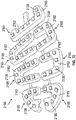
FIG. 31 is a schematic illustration in bottom view of a fifth chamber. -
FIG. 32 is a schematic cross-sectional illustration of the fifth chamber taken at lines 32-32 inFIG. 31 . -
FIG. 33 is a schematic cross-sectional illustration of the fifth chamber taken at lines 33-33 inFIG. 32 . -
FIG. 34 is a schematic illustration in bottom view of a sixth chamber. -
FIG. 35 is a schematic cross-sectional illustration of the sixth chamber taken at lines 35-35 inFIG. 34 . -
FIG. 36 is a schematic illustration in bottom view of a seventh chamber. -
FIG. 37 is a schematic illustration in bottom view of an eighth chamber. -
FIG. 38 is a schematic illustration in top view of a ninth chamber. -
FIG. 39 is a schematic cross-sectional illustration of the ninth chamber ofFIG. 38 taken at lines 39-39 inFIG. 38 . -
FIG. 40 is a schematic cross-sectional illustration of the ninth chamber ofFIG. 38 taken at lines 40-40 inFIG. 38 . -
FIG. 41 is a schematic cross-sectional illustration of the ninth chamber ofFIG. 38 taken at lines 41-41 inFIG. 38 . -
FIG. 42 is a schematic cross-sectional illustration of the ninth chamber ofFIG. 38 taken at lines 42-42 inFIG. 38 . -
FIG. 43 is a schematic cross-sectional illustration of the ninth chamber ofFIG. 38 taken at lines 43-43 inFIG. 38 . -
FIG. 44 is a schematic illustration in a lateral side elevational view of the ninth chamber ofFIG. 38 . -
FIG. 45 is a schematic illustration in bottom view of the ninth chamber ofFIG. 38 . -
FIG. 46 is a schematic illustration in a medial side elevational view of the ninth chamber ofFIG. 38 . -
FIG. 47 is a schematic illustration in bottom view of an outsole for use with the ninth chamber ofFIG. 38 . -
FIG. 48 is a schematic illustration in top view of the outsole ofFIG. 47 . -
FIG. 49 is a schematic illustration in top view of a midsole for use with the ninth chamber ofFIG. 38 . -
FIG. 50 is a schematic illustration in bottom view of the midsole ofFIG. 49 . -
FIG. 51 is a schematic illustration in top view of a sole structure including the ninth chamber ofFIG. 38 , the outsole ofFIG. 47 , and the midsole ofFIG. 49 . -
FIG. 52 is a schematic cross-sectional illustration of the sole structure ofFIG. 51 taken at lines 52-52 inFIG. 51 . -
FIG. 53 is a schematic cross-sectional illustration of the sole structure ofFIG. 51 taken at lines 53-53 inFIG. 51 . -
FIG. 54 is a schematic cross-sectional illustration of the sole structure ofFIG. 51 taken at lines 54-54 inFIG. 51 . -
FIG. 55 is a schematic cross-sectional illustration of the sole structure ofFIG. 51 taken at lines 55-55 inFIG. 51 . -
FIG. 56 is a schematic cross-sectional illustration of the sole structure ofFIG. 51 taken at lines 56-56 inFIG. 51 and showing an upper in phantom. -
FIG. 57 is a schematic illustration in a lateral side elevational view of the sole structure ofFIG. 51 . -
FIG. 58 is a schematic illustration in bottom view of the sole structure ofFIG. 51 . -
FIG. 59 is a schematic illustration in a medial side elevational view of the sole structure ofFIG. 51 . -
FIG. 60 is a schematic illustration in front elevational view of the sole structure ofFIG. 51 . -
FIG. 61 is a schematic illustration in rear elevational view of the sole structure ofFIG. 51 . -
FIG. 62 is a schematic perspective illustration of another configuration of an article of footwear and showing a lateral side and a bottom. -
FIG. 63 is a schematic perspective illustration of the article of footwear ofFIG. 62 and showing a medial side. -
FIG. 64 is a schematic cross-sectional illustration of the article of footwear ofFIG. 62 taken at lines 64-64 inFIG. 62 . -
FIG. 65 is a schematic cross-sectional illustration of the article of footwear ofFIG. 62 taken at lines 65-65 inFIG. 62 . -
FIG. 66 is a schematic perspective illustration of another configuration of an article of footwear. -
FIG. 67 is a schematic illustration in exploded cross-sectional view of a sole structure of the article of footwear ofFIG. 62 and a mold assembly for a manufacturing process. -
FIG. 68 is a schematic illustration in a lateral side elevational view of an embodiment of an article of footwear. -
FIG. 69 is a schematic illustration in bottom view of the article of footwear ofFIG. 68 . -
FIG. 70 is a cross-sectional view of the article of footwear ofFIG. 69 . -
FIG. 71 is a schematic illustration in bottom view of a forefoot sole structure of an article of footwear. -
FIG. 72 is a schematic illustration in bottom perspective view of a forefoot outsole ofFIG. 69 . -
FIG. 73 is a schematic illustration in an exploded view illustrating a relationship between a forefoot outsole and a forefoot component that form a forefoot sole structure ofFIG. 69 . -
FIG. 74 is a schematic illustration in an exploded view illustrating a relationship between a heel outsole and a heel component that form a heel sole structure ofFIG. 69 . -
FIG. 75 is a schematic illustration in an exploded view illustrating a relationship between a forefoot outsole and a forefoot component that form a forefoot sole structure ofFIG. 71 . -
FIG. 76 is a schematic illustration in a cross-sectional view of an open mold illustrating a relationship of the parts for forming a forefoot sole structure ofFIG. 71 in the mold. -
FIG. 77 is a schematic illustration in a cross-sectional view of a closed mold illustrating a forefoot sole structure ofFIG. 71 formed in the mold. -
FIG. 78 is a schematic illustration in a cross-sectional view of an open mold illustrating the relationship of the parts for forming a heel sole structure like that ofFIG. 69 in the mold. -
FIG. 79 is a schematic illustration in cross-sectional view of a partially-formed heel sole structure ofFIG. 78 in a partially-open mold. -
FIG. 80 is a schematic illustration in cross-sectional view of a closed mold illustrating the heel sole structure ofFIG. 79 formed in the mold. -
FIG. 81 is a schematic illustration in cross-sectional view of a heel sole structure ofFIG. 80 removed from the mold opened after forming the structure. -
FIG. 82 is a schematic illustration in cross-sectional view of an embodiment of a heel sole structure. -
FIG. 83 is a schematic illustration in cross-sectional view of another embodiment of a heel sole structure. -
FIG. 84 is a schematic illustration in cross-sectional view of still another embodiment of a heel sole structure. -
FIG. 85 is a schematic illustration in bottom view of an embodiment of an article of footwear; -
FIG. 86 is a schematic illustration in cross-sectional view of an open mold illustrating a relationship of parts for producing an article. -
FIG. 87 is a schematic illustration in cross-sectional view of a closed mold illustrating a relationship of parts for producing the article ofFIG. 86 . - An article of footwear comprises a barrier having a heel region, a midfoot region forward of the heel region, and a forefoot region forward of the midfoot region. The barrier includes a first portion that includes a first surface of the barrier, and a second portion that includes a second surface of the barrier opposite from the first surface. The barrier includes a bond that secures the first portion of the barrier and the second portion of the barrier to one another and separates the barrier into a first interior cavity and a second interior cavity that retain fluid, with the second interior cavity extending only in the forefoot region forward of the first interior cavity. A plurality of tethers are in each of the first interior cavity and the second interior cavity and operatively connect the first portion to the second portion.
- In an embodiment, the first tethers have a first configuration, and the second tethers have a second configuration. For example, the first configuration may include a first length, and the second configuration may include a second length less than the first length. In an embodiment, the first portion and the second portion are first and second polymer sheets.
- In an embodiment, the first interior cavity extends in the heel region, the midfoot region, and the forefoot region, and the second interior cavity extends only in the forefoot region forward of the first interior cavity.
- In an embodiment, the first tethers are in the heel region of the first interior cavity and the second tethers are in the midfoot region of the first interior cavity. In an embodiment, the first interior cavity extends from a medial side of the barrier to a lateral side of the barrier, and the second interior cavity extends from the medial side of the barrier to the lateral side of the barrier.
- In an embodiment, the barrier includes a groove extending from the medial side of the barrier to the lateral side of the barrier between the first interior cavity and the second interior cavity. The groove may have a medial end at the medial side of the barrier, a lateral end at the lateral side of the barrier, and a midportion that arcs forward between the medial end and the lateral end. In an embodiment, the barrier includes a channel that traverses the groove and fluidly connects the first interior cavity and the second interior cavity. The channel may be disposed between a longitudinal midline of the barrier and the lateral side of the barrier.
- The barrier may have at least one notch in a periphery of the heel portion. The at least one notch may include a first notch in the periphery of the heel portion at a medial side of the barrier, and a second notch in the periphery of the heel portion at a lateral side of the barrier. In an embodiment, the barrier has a third notch forward of the first notch at the periphery of the heel portion at the medial side of the barrier, and a fourth notch forward of the second notch at the periphery of the heel portion at the lateral side of the barrier.
- The article of footwear may further comprise an outsole secured to the second surface of the second portion of the barrier. The outsole includes a first outsole portion extending under the first interior cavity, and a second outsole portion extending under the second interior cavity and separated from the first outsole portion by a gap. The outsole may include a third outsole portion that traverses the gap and connects the first outsole portion and the second outsole portion such that the outsole is a unitary, one-piece outsole. The third outsole portion may be secured to the channel of the barrier that connects the first interior cavity and the second interior cavity.
- In an embodiment in which the barrier includes a groove that extends from the medial side of the barrier to the lateral side of the barrier between the first interior cavity and the second interior cavity, the first outsole portion may be secured to and extend along a first wall of the second portion of the barrier in the groove. The second outsole portion may be secured to and extend along a second wall of the second barrier portion in the groove. The first wall and the second wall may extend from the medial side of the barrier to the lateral side of the barrier, with the first wall facing the second wall.
- The first outsole portion may include a medial sidewall secured to and confronting the medial side of the barrier at the heel portion, and a lateral sidewall secured to and confronting the lateral side of the barrier at the heel portion. One of the medial sidewall of the first outsole portion and the lateral sidewall of the first outsole portion extends along and confronts the heel portion of the barrier in the at least one notch. For example, if the notch is in the medial side of the barrier, the medial sidewall of the first outsole portion extends along and confronts the medial side of the barrier in the notch. If the notch is in the lateral side of the barrier, the lateral sidewall of the first outsole portion extends along and confronts the lateral side of the barrier in the notch.
- In an embodiment, the medial sidewall of the first outsole portion is taller than the lateral sidewall of the first outsole portion. Accordingly, the lateral side of the barrier may be exposed above the lateral sidewall of the first outsole portion.
- The article of footwear may further comprise a midsole secured to the first surface of the barrier. In an embodiment, the midsole has an aperture extending completely through the midsole and overlaying the heel portion of the barrier. The midsole may have an aperture extending completely through the midsole and overlaying the forefoot portion of the barrier at the bond.
- The first configuration of the first plurality of tethers may impart a first compression characteristic to the chamber at a first area, and the second configuration of the second plurality of tethers may impart a second compression characteristic to the chamber at a second area. The second compression characteristic is different than the first compression characteristic.
- The first and second compression characteristics can be imparted due to a variety of configurations of the tethers. For example, in an embodiment, the first configuration of the first plurality of tethers includes a first density and the second configuration of the second plurality of tethers includes a second density different than the first density. In the same or a different embodiment, the first configuration includes a first material, and the second configuration includes a second material different than the first material. In the same or a different embodiment, the first configuration includes a first length, and the second configuration includes a second length different than the first length.
- The above features and advantages and other features and advantages of the present teachings are readily apparent from the following detailed description of the modes for carrying out the present teachings when taken in connection with the accompanying drawings.
- "A," "an," "the," "at least one," and "one or more" are used interchangeably to indicate that at least one of the items is present. A plurality of such items may be present unless the context clearly indicates otherwise. All numerical values of parameters (e.g., of quantities or conditions) in this specification, unless otherwise indicated expressly or clearly in view of the context, including the appended claims, are to be understood as being modified in all instances by the term "about" whether or not "about" actually appears before the numerical value. "About" indicates that the stated numerical value allows some slight imprecision (with some approach to exactness in the value; approximately or reasonably close to the value; nearly). If the imprecision provided by "about" is not otherwise understood in the art with this ordinary meaning, then "about" as used herein indicates at least variations that may arise from ordinary methods of measuring and using such parameters. In addition, a disclosure of a range is to be understood as specifically disclosing all values and further divided ranges within the range.
- The terms "comprising," "including," and "having" are inclusive and therefore specify the presence of stated features, steps, operations, elements, or components, but do not preclude the presence or addition of one or more other features, steps, operations, elements, or components. Orders of steps, processes, and operations may be altered when possible, and additional or alternative steps may be employed. As used in this specification, the term "or" includes any one and all combinations of the associated listed items. The term "any of' is understood to include any possible combination of referenced items, including "any one of" the referenced items. The term "any of" is understood to include any possible combination of referenced claims of the appended claims, including "any one of' the referenced claims.
- Those having ordinary skill in the art will recognize that terms such as "above," "below," "upward," "downward," "top," "bottom," etc., are used descriptively relative to the figures, and do not represent limitations on the scope of the invention, as defined by the claims.
- The following discussion and accompanying figures disclose an article of footwear, as well as various fluid-filled chambers that may be incorporated into the footwear. Concepts related to the chambers are disclosed with reference to footwear that is suitable for running. The chambers are not limited to footwear designed for running, however, and may be utilized with a wide range of athletic footwear styles, including basketball shoes, cross-training shoes, cycling shoes, football shoes, soccer shoes, tennis shoes, and walking shoes, for example. The chambers may also be utilized with footwear styles that are generally considered to be non-athletic, including dress shoes, loafers, sandals, and boots. The concepts disclosed herein may, therefore, apply to a wide variety of footwear styles, in addition to the specific style discussed in the following material and depicted in the accompanying figures. The chambers may also be utilized with a variety of other products, including backpack straps, mats for yoga, seat cushions, and protective apparel, for example.
- An article of
footwear 10 is depicted inFIGS. 1-3 as including an upper 20 and asole structure 30. For reference purposes,footwear 10 may be divided into three general regions: aforefoot region 11, amidfoot region 12, and aheel region 13, as shown inFIGS. 1 and2 .Footwear 10 also includes alateral side 14 and amedial side 15.Forefoot region 11 generally includes portions offootwear 10 corresponding with the toes and the joints connecting the metatarsals with the phalanges.Midfoot region 12 generally includes portions offootwear 10 corresponding with the arch area of the foot, andheel region 13 corresponds with rear portions of the foot, including the calcaneus bone.Lateral side 14 andmedial side 15 extend through each of regions 11-13 and correspond with opposite sides offootwear 10. Regions 11-13 and sides 14-15 are not intended to demarcate precise areas offootwear 10. Rather, regions 11-13 and sides 14-15 are intended to represent general areas offootwear 10 to aid in the following discussion. In addition tofootwear 10, regions 11-13 and sides 14-15 may also be applied to upper 20,sole structure 30, and individual elements thereof. -
Upper 20 is depicted as having a substantially conventional configuration incorporating a plurality of material elements (e.g., textiles, foam, leather, and synthetic leather) that are stitched or adhesively bonded together to form an interior void for securely and comfortably receiving a foot. The material elements may be selected and located with respect to upper 20 in order to selectively impart properties of durability, air-permeability, wear-resistance, flexibility, and comfort, for example. Anankle opening 21 inheel region 13 provides access to the interior void. In addition, upper 20 may include alace 22 that is utilized in a conventional manner to modify the dimensions of the interior void, thereby securing the foot within the interior void and facilitating entry and removal of the foot from the interior void.Lace 22 may extend through apertures in upper 20, and a tongue portion of
upper 20 may extend between the interior void andlace 22. Given that various aspects of the present discussion primarily relate tosole structure 30, upper 20 may exhibit the general configuration discussed above or the general configuration of practically any other conventional or non-conventional upper. Accordingly, the structure of upper 20 may vary significantly within the scope of the present invention. -
Sole structure 30 is secured to upper 20 and has a configuration that extends between upper 20 and the ground. In addition to attenuating ground reaction forces (i.e., providing cushioning for the foot),sole structure 30 may provide traction, impart stability, and limit various foot motions, such as pronation. The primary elements ofsole structure 30 are amidsole element 31, anoutsole 32, and achamber 33.Midsole element 31 is secured to a lower area of upper 20 and may be formed from various polymer foam materials (e.g., polyurethane or ethylvinylacetate foam) that extend through each of regions 11-13 and betweensides midsole element 31 at least partially envelops or receiveschamber 33, which will be discussed in greater detail below.Outsole 32 is secured to a lower surface ofmidsole element 31 and may be formed from a textured, durable, and wear-resistant material (e.g., rubber) that forms the ground-contacting portion offootwear 10. In addition tomidsole element 31,outsole 32, andchamber 33,sole structure 30 may incorporate one or more support members, moderators, or reinforcing structures, for example, that further enhance the ground reaction force attenuation characteristics ofsole structure 30 or the performance properties offootwear 10.Sole structure 30 may also incorporate asockliner 34, as depicted inFIG. 3 , that is located within a lower portion of the void in upper 20 and is positioned to contact a plantar (i.e., lower) surface of the foot to enhance the comfort offootwear 10. - When incorporated into
sole structure 30,chamber 33 has a shape that fits within a perimeter ofmidsole element 31 and extends throughheel region 13, extends intomidfoot region 12, and also extends fromlateral side 14 to medial
side 15. Althoughchamber 33 is depicted as being exposed through the polymer foam material ofmidsole element 31,chamber 33 may be entirely encapsulated withinmidsole element 31 in some configurations offootwear 10. When the foot is located within upper 20,chamber 33 extends under a heel area of the foot in order to attenuate ground reaction forces that are generated whensole structure 30 is compressed between the foot and the ground during various ambulatory activities, such as running and walking. In some configurations,chamber 33 may protrude outward frommidsole element 31 or may extend further intomidfoot region 12 and may also extend forward to forefootregion 11. Accordingly, the shape and dimensions ofchamber 33 may vary significantly to extend through various areas offootwear 10. Moreover, any of a variety ofother chambers chamber 33 infootwear 10. - The primary components of
chamber 33, which is depicted individually inFIGS. 4-8B , are abarrier 40 and atether element 50.Barrier 40 forms an exterior ofchamber 33 and (a) defines an interior cavity that receives both a pressurized fluid andtether element 50 and (b) provides a durable sealed barrier for retaining the pressurized fluid withinchamber 33. The polymer material of
barrier 40 includes a first orupper barrier portion 41, an opposite second orlower barrier portion 42, and asidewall barrier portion 43 that extends around a periphery ofchamber 33 and betweenbarrier portions Tether element 50 is located within the interior cavity and has a configuration that includes a first or upper
plate 51, an opposite second orlower plate 52, and a plurality oftethers 53 that extend betweenplates upper plate 51 is secured to an inner surface ofupper barrier portion 41,lower plate 52 is secured to an inner surface oflower barrier portion 42. Either adhesive bonding or thermobonding, for example, may be utilized to securetether element 50 tobarrier 40. - In
manufacturing chamber 33, a pair of polymer sheets may be molded and bonded during a thermoforming process to define barrier portions 41-43. More particularly, the thermoforming process (a) imparts shape to one of the polymer sheets in order to formupper barrier portion 41, (b) imparts shape to the other of the polymer sheets in order to formlower barrier portion 42 andsidewall barrier portion 43, and (c) forms aperipheral bond 44 that joins a periphery of the polymer sheets and extends around an upper area ofsidewall barrier portion 43. The thermoforming process may also locatetether element 50 withinchamber 33 andbond tether element 50 to each ofbarrier portions chamber 33. Other processes that utilize blowmolding, rotational molding, or the bonding of polymer sheets without thermoforming may also be utilized to manufacturechamber 33. - Following the thermoforming process, a fluid may be injected into the interior cavity and pressurized. The pressurized fluid exerts an outward force upon
barrier 40 andplates barrier portions Tether element 50, however, is secured to each ofbarrier portions chamber 33 when pressurized. More particularly, tethers 53 extend across the interior cavity and are placed in tension by the outward force of the pressurized fluid uponbarrier 40, thereby preventingbarrier 40 from expanding outward and retaining the intended shape ofchamber 33. Whereasperipheral bond 44 joins the polymer sheets to form a seal that prevents the fluid from escaping,tether element 50 preventschamber 33 from expanding outward or otherwise distending due to the pressure of the fluid. That is, tether
element 50 effectively limits the expansion ofchamber 33 to retain an intended shape of surfaces ofbarrier portions - The fluid within
chamber 33 may be pressurized between zero and three-hundred-fifty kilopascals (i.e., approximately fifty-one pounds per square inch) or more. In addition to air and nitrogen, the fluid may include any of the gasses disclosed inU.S. Pat. No. 4,340,626 to Rudy , which is incorporated by reference in its entirety. In some configurations,chamber 33 may incorporate a valve or other structure that permits the wearer or another individual to adjust the pressure of the fluid. - A wide range of polymer materials may be utilized for
barrier 40. In selecting materials forbarrier 40, engineering properties of the material (e.g., tensile strength, stretch properties, fatigue characteristics, dynamic modulus, and loss tangent) as well as the ability of the material to prevent the diffusion of the fluid contained bybarrier 40 may be considered. When formed of thermoplastic urethane, for example,barrier 40 may have a thickness of approximately 1.0 millimeter, but the thickness may range from 0.25 to 4.0 millimeters or more, for example. In addition to thermoplastic urethane, examples of polymer materials that may be suitable forbarrier 40 include polyurethane, polyester, polyester polyurethane, and polyether polyurethane.Barrier 40 may also be formed from a material that includes alternating layers of thermoplastic polyurethane and ethylene-vinyl alcohol copolymer, as disclosed inU.S. Pat. Nos. 5,713,141 and5,952,065 to Mitchell, et al. which are incorporated by reference in their entireties. A variation upon this material may also be utilized, wherein a center layer is formed of ethylene-vinyl alcohol copolymer, layers adjacent to the center layer are formed of thermoplastic polyurethane, and outer layers are formed of a regrind material of thermoplastic polyurethane and ethylene-vinyl alcohol copolymer. Another suitable material forbarrier 40 is a flexible microlayer membrane that includes alternating layers of a gas barrier material and an elastomeric material, as disclosed inU.S. Pat. Nos. 6,082,025 and6,127,026 to Bonk, et al. , which are incorporated by reference in their entireties. Additional suitable materials are disclosed inU.S. Pat. Nos. 4,183,156 and4,219,945 to Rudy , which are incorporated by reference in their entireties. Further suitable materials include thermoplastic films containing a crystalline material, as disclosed inU.S. Pat. Nos. 4,936,029 and5,042,176 to Rudy , which are incorporated by reference in their entireties, and polyurethane including a polyester polyol, as disclosed inU.S. Pat. Nos. 6,013,340 ;6,203,868 ; and6,321,465 to Bonk, et al. , which are incorporated by reference in their entireties. - As discussed above,
tether element 50 includesupper plate 51, the oppositelower plate 52, and the plurality oftethers 53 that extend betweenplates plates Tethers 53 are secured to each ofplates space plates plates barrier portions -
Plates chamber 33. Given thatplates chamber 33 exhibit a corresponding planar configuration. As discussed in greater detail below, however, one or both ofplates chamber 33. Althoughplates chamber 33,plates FIGS. 8A and 8B as being spaced inward fromsidewall barrier portion 43. That is,plates chamber 33. In this configuration,upper plate 51 extends adjacent to at least fifty percent ofupper barrier portion 41, andlower plate 52 extends adjacent to at least fifty percent oflower barrier portion 42. Withouttether element 50,chamber 33 would effectively bulge or otherwise distend to a generally rounded shape.Plates barrier portions plates plates plates barrier portions barrier portions barrier portions plates chamber 33 such thatplates barrier portions chamber 33 remains suitably-shaped for use infootwear 10. - A variety of structures may be utilized to secure
tethers 53 to each ofplates FIG. 8A , for example,
tethers 53 are merely secured toupper plate 51, and a similar configuration may be utilized to jointethers 53 tolower plate 52. A variety of securing structures may also be utilized. Referring toFIG. 9A , ends oftethers 53 include enlarged areas that may assist with anchoringtethers 53 withinupper plate 51.FIG. 9B depicts a configuration wherein each oftethers 53 are secured to arestraint 54 located on an upper surface of upper plate 51 (i.e., betweenupper plate 51 and upper barrier portion 41). Each ofrestraints 54 may have the configuration of a disk that is joined to an end of one oftethers 53. In another configuration, as depicted inFIG. 9C , asingle tether 53 extends throughupper plate 51 in two locations and runs along the upper surface ofupper plate 51. Thevarious tethers 53 may, therefore, be formed from a single strand or other element that repeatedly passes throughplates individual tethers 53 may be secured to a lower surface ofupper plate 51, as depicted inFIG. 9D , with an adhesive or thermobonding. Accordingly, tethers 53 may be secured toplates -
Plates plates tether element 50. In some configurations ofchamber 33,plates plates
plates material forming barrier 40 generally has lesser stiffness thanplates barrier 40 during walking, running, or other ambulatory activities,plates material forming plates material forming barrier 40. -
Tethers 53 may be formed from any generally one-dimensional material. As utilized with respect to the present invention, the term "one-dimensional material" or variants thereof is intended to encompass generally elongate materials exhibiting a length that is substantially greater than a width and a thickness. Accordingly, suitable materials fortethers 53 include various strands, filaments, fibers, yarns, threads, cables, or ropes that are formed from rayon, nylon, polyester, polyacrylic, silk, cotton, carbon, glass, aramids (e.g., para-aramid fibers and metaaramid fibers), ultra high molecular weight polyethylene, liquid crystal polymer, copper, aluminum, and steel. Whereas filaments have an indefinite length and may be utilized individually astethers 53, fibers have a relatively short length and generally go through spinning or twisting processes to produce a strand of suitable length. An individual filament utilized intethers 53 may be formed form a single material (i.e., a monocomponent filament) or from multiple materials (i.e., a bicomponent filament). Similarly, different filaments may be formed from different materials. As an example, yarns utilized astethers 53 may include filaments that are each formed from a common material, may include filaments that are each formed from two or more different materials, or may include filaments that are each formed from two or more different materials. Similar concepts also apply to threads, cables, or ropes. The thickness oftethers 53 may also vary significantly to range from 0.03 millimeters to more than 5 millimeters, for example. Although one-dimensional materials will often have a cross-section where width and thickness are substantially equal (e.g., a round or square cross-section), some one-dimensional materials may have a width that is greater than a thickness (e.g., a rectangular, oval, or otherwise elongate cross-section). Despite the greater width, a material may be considered one-dimensional if a length of the material is substantially greater than a width and a thickness of the material. -
Tethers 53 are arranged in rows that extend longitudinally along the lengths ofplate FIG. 8B , ninetethers 53 extend across the width ofchamber 33, and each of the nine tethers are within one of the longitudinally-extending rows. Whereas the central row oftethers 53 is oriented to have a generally vertical orientation, the more peripheral rows oftethers 53 are oriented diagonally. That is, tethers 53 may be secured to offset areas ofplates tethers 53 relates to the stability offootwear 10. Referring toFIG. 10A , aforce 16 is shown as compressingsole structure 30 and thrusting towardlateral side 14, which may correspond to a cutting motion that is utilized in many athletic activities to move an individual side-to-side. Whenforce 16 deformschamber 33 in this manner,
tethers 53 adjacent tomedial side 15 are placed in tension due to their sloping or diagonal orientation, as represented byvarious arrows 17. The tension in
tethers 53 adjacent tomedial side 15 resists the deformation ofchamber 33, thereby resisting the collapse oflateral side 14. Similarly, referring toFIG. 10B ,force 16 is shown as compressingsole structure 30 and thrusting towardmedial side 15, which may also correspond to a cutting motion. Whenforce 16 deformschamber 33 in this manner, tethers 53 adjacent tolateral side 14 are placed in tension due to their sloping or diagonal orientation, as represented by thevarious arrows 17. The tension intethers 53 adjacent tolateral side 14 resists the deformation ofchamber 33, thereby resisting the collapse ofmedial side 15. Accordingly, the diagonal orientation oftethers 53 resists deformation inchamber 33, thereby enhancing the overall stability offootwear 10 during walking, running, or other ambulatory activities. - The overall shape of
chamber 33 and the areas offootwear 10 in whichchamber 33 is located may vary significantly. Referring toFIG. 11A ,chamber 33 has a generally round configuration that may be located solely withinheel region 13, for example. Another shape is depicted inFIG. 11B , whereinchamber 33 has a configuration that extends through bothheel region 13 andmidfoot region 12. In thisconfiguration chamber 33 may replacemidsole element 31 such that
chamber 33 extends fromlateral side 14 tomedial side 15 and from upper 20 tooutsole 32. A similar configuration is depicted inFIG. 11C , whereinchamber 33 has a shape that fits within a perimeter ofsole structure 30 and extends under substantially all of the foot, thereby corresponding with a general outline of the foot. In thisconfiguration chamber 33 may also replacemidsole element 31 such that
chamber 33 extends fromlateral side 14 tomedial side 15, fromheel region 13 to forefootregion 11, and from upper 20 tooutsole 32. - Although the structure of
chamber 33 discussed above and depicted in the figures provides a suitable example of a configuration that may be utilized infootwear 10, a variety of other configurations may also be utilized. Referring toFIG. 12A ,chamber 33 exhibits a tapered configuration. One manner of imparting the tapered configuration relates to the relative lengths oftethers 53. Whereas
tethers 53 are relatively long in the areas ofchamber 33 exhibiting greater
thicknesses, tethers 53 are relatively short in the areas ofchamber 33 exhibiting lesser thicknesses. By varying the lengths oftethers 53, therefore, tapers or other features may be incorporated intochamber 33. The taper inFIG. 12A extends fromlateral side 14 tomedial side 15. A taper may also extend fromheel region 13 to forefootregion 12, as in the configuration ofchamber 33 depicted inFIG. 11C . Another configuration ofchamber 33 is depicted inFIG. 12B , wherein a central area ofchamber 33 is depressed relative to the peripheral areas. More particularly,upper plate 51 is contoured to have anon-planar configuration, thereby forming a depression in the central area. When incorporated intofootwear 10, the depression may correspond with the location of the heel of the wearer, thereby providing an area for securely-receiving the heel. A similar depression is also formed in the configuration ofchamber 33 depicted inFIG. 11C . In other configurations,upper plate 51 may be contoured to form a protruding arch support area, for example. As a related matter, the relative lengths oftethers 53 vary throughout the configuration depicted inFIG. 12B . More particularly, tethers 53 in the peripheral areas have greater lengths thantethers 53 in the central area. - Various aspects relating to
tethers 53 may also vary. Referring toFIG. 12C , each oftethers 53 exhibit a diagonal orientation. In some configurations, tethers 53 may cross each other to form x-shaped structures with opposing diagonal orientations, as depicted inFIG. 12D . Additionally, the spacing betweenadjacent tethers 53 may vary significantly, as depicted inFIG. 12E , and tethers 53 may be absent from some areas ofchamber 33. Whiletethers 53 may be formed from any generally one-dimensional material, a variety of other materials or structures may be located betweenplates barrier 40 from expanding outward and retain the intended shape ofchamber 33. Referring toFIG. 12F , for example, a variety of other tethers are located betweenplates member 55 and afoam member 56 are bonded toplates textile member 57 may also be utilized and may have the configuration of either a woven or knit textile. In some configurations,textile member 57 may be a spacer knit textile. Atruss member 58 may also be utilized inchamber 33 and has the configuration of a semi-rigid polymer element that extends betweenplates member 59 that freely collapses but also resists tension may be utilized. Accordingly, a variety of other materials or structures may be utilized withtethers 53 or in place oftethers 53. - Although a
single plate 51 and asingle plate 52 may be utilized inchamber 33, some configurations may incorporatemultiple plates FIG. 12G , twoplates 51 and twoplates 52 are located within the interior cavity ofbarrier 40. An advantage to this configuration is that each ofplates 51 may deflect independently when compressed by the foot. A similar configuration is depicted inFIG. 12H , wherein acentral bond 45 joinsbarrier portions chamber 33.Bond 45 may, for example, form separate subchambers withinchamber 33, which may be pressurized differently to affect the compressibility of different areas ofchamber 33. As an additional matter, each ofplates 51 or each ofplates 52 may be formed from different materials to impart different properties to various areas ofchamber 33. - A further configurations of
chamber 33 is depicted inFIG. 12I as including atether element 60 that has anupper tie piece 61, alower tie piece 62, and atether 63. Whereasupper tie piece 61 is secured, bonded, or otherwise joined toupper barrier portion 41,lower tie piece 62 is secured, bonded, or otherwise joined tolower barrier portion 42. Additionally,tether 63 is joined to each oftie pieces tether 63 is placed in tension by the outward force of the pressurized fluid withinchamber 33.Tie pieces plates single tether 63 or a relatively small number oftethers 63, rather than multiple tethers. Althoughtie pieces tie pieces tethers 63, various contours may be imparted tochamber 33. For example,FIG. 12J depictschamber 33 as having a tapered configuration, andFIG. 12K depictschamber 33 as having a central depression. In further configurations,tie pieces tethers 63, as depicted inFIG. 12L . - Some configurations of
chamber 33 may have both a tether
element 50 and one ormore tether elements 60, as depicted inFIG. 12M . That is,chamber 33 may have (a) a first area that includestether element 50 and (b) a second area that includes a plurality oftether elements 60. Given the difference in sizes oftether element 50 and theindividual tether elements 60, the compression characteristics ofchamber 33 differ in areas wheretether element 50 is present and in areas wheretether elements 60 are present. More particularly, the deflection ofchamber 33 when a force is applied to a particular area may be different, depending upon the type of tether element that is utilized. Accordingly,tether element 50 andtether elements 60 may both be utilized inchamber 33 to impart different compression characteristics to different areas ofchamber 33. - As discussed above,
chamber 33 may have (a) a first area that includestether element 50 and (b) a second area that includes a plurality of tether
elements 60 in order to impart different compression characteristics to the first and second areas ofchamber 33. As an example, the plurality oftether elements 60 may be utilized inlateral side 14 to impart greater deflection as the heel compressessole structure 30, andtether element 50 may be utilized inmedial side 15 to impart a stiffer deflection as the foot rolls or pronates towardmedial side 15. As another example, the plurality oftether elements 60 may be utilized inheel region 13 to impart greater deflection as the heel compressessole structure 30, andtether element 50 may be utilized inforefoot region 11 to impart a stiffer deflection. In other configurations, the plurality oftether elements 60 may be utilized in forefoot
region 11 andtether elements 60 may be utilized inheel region 13. In either configuration, however,tether element 50 and a plurality oftether elements 60 may be utilized in combination to impart different compression characteristics to different areas offootwear 10. Moreover, any of the additional tether element configurations shown inFIG. 12F may be utilized in combination withtether element 50 and one or more oftether elements 60 to vary the compression characteristics in different areas ofchamber 33 or other chambers. - Some conventional chambers utilize bonds between opposite surfaces to prevent the barrier from expanding outward and retaining the intended shape of the chamber. Often, the bonds form indentations or depressions in the upper and lower surfaces of the chamber and have different compression characteristics than other areas of the chamber (i.e., the areas without the bonds). Referring to
FIG. 12N ,chamber 33 has a configuration wherein areas with the various tether
elements 60 form indentations inbarrier portions barrier portions tie pieces barrier 40. In some configurations, these depressions may be molded or otherwise formed inbarrier portions barrier 40 may take this shape due to the pressure of the fluid withinbarrier 40. In other configurations, a variety of other tensile members (e.g., foam members, spacer textiles) may be utilized in place oftether elements 60. - The various configurations of
chamber 33 discussed above provide examples of fluid-filled chambers that may be incorporated intofootwear 10 or other articles of footwear. A variety of other fluid-filled chambers may also be incorporated intofootwear 10 or the other articles of footwear, including achamber 100. Referring toFIGS. 13-17B ,chamber 100 has abarrier 110 and a plurality oftether elements 120.Barrier 110 forms an exterior ofchamber 100 and defines an interior cavity for receiving both a pressurized fluid andtether elements 120.Barrier 110 includes a first orupper barrier portion 111, an opposite second orlower barrier portion 112, and asidewall barrier portion 113 that extends around a periphery ofchamber 100 and betweenbarrier portions
barrier 110 includes aperipheral bond 114, which may be absent in some configurations. Tetherelements 120 are located within the interior cavity and have the configurations of textile or polymer sheets, for example. Either adhesive bonding or thermobonding, for example, may be utilized to securetether elements 120 tobarrier 110. Any of the manufacturing processes, materials, fluids, fluid pressures, and other features ofbarrier 40 discussed above may also be utilized forbarrier 110. - Tether
elements 120 are secured to each of barrier
portions chamber 100 when pressurized. More particularly,tether elements 120 extend across the interior cavity and are placed in tension by the outward force of the pressurized fluid upon
barrier 110, thereby preventingbarrier 110 from expanding outward and retaining the intended shape ofchamber 100. That is,tether elements 120 prevent
chamber 100 from expanding outward or otherwise distending due to the pressure of the fluid. - Although a variety of materials may be utilized, tether
elements 120 may be formed from any generally two-dimensional material. As utilized with respect to the present invention, the term "two-dimensional material" or variants thereof is intended to encompass generally flat materials exhibiting a length and a width that are substantially greater than a thickness. Accordingly, suitable materials fortether elements 120 include various textiles, polymer sheets, or combinations of textiles and polymer sheets, for example. Textiles are generally manufactured from fibers, filaments, or yarns that are, for example, either (a) produced directly from webs of fibers by bonding, fusing, or interlocking to construct non-woven fabrics and felts or (b) formed through a mechanical manipulation of yarn to produce a woven or knitted fabric. The textiles may incorporate fibers that are arranged to impart one-directional stretch or multi-directional stretch. The polymer sheets may be extruded, rolled, or otherwise formed from a polymer material to exhibit a generally flat aspect. Two-dimensional materials may also encompass laminated or otherwise layered materials that include two or more layers of textiles, polymer sheets, or combinations of textiles and polymer sheets. In addition to textiles and polymer sheets, other two-dimensional materials may be utilized fortether elements 120. In some configurations, mesh materials or perforated materials may be utilized fortether elements 120. - Each of
tether elements 120 are formed from a single element of a two-dimensional material, such as a textile or polymer sheet. Moreover, each oftether elements 120 have anupper end area 121, alower end area 122, and acentral area 123. Whereasupper end area 121 is secured, bonded, or otherwise joined toupper barrier portion 111,lower end area 122 is secured, bonded, or otherwise joined tolower barrier portion 112. In this configuration,central area 123 extends through the interior cavity and is placed in tension by the outward force of the pressurized fluid withinchamber 100. - Although the structure of
chamber 100 discussed above and depicted in the figures provides a suitable example of a configuration that may be utilized infootwear 10, a variety of other configurations may also be utilized. Referring toFIG. 18A ,tether elements 120 are secured to offset areas ofbarrier portions central areas 123. More particularly, endareas central areas 123. As discussed above, the diagonal orientation resists deformation inchamber 100, thereby enhancing the overall stability offootwear 10 during walking, running, or other ambulatory activities. Referring toFIG. 18B , asingle tether element 120 is joined tobarrier portions chamber 100. By modifying the lengths oftether elements 120, various contours may be imparted tochamber 100. For example,FIG. 18C depictschamber 100 as having a tapered configuration, andFIG. 18D depictschamber 100 as having a central depression. Each of these contours are formed by selectively utilizingtether elements 120 with varying lengths. - In the various configurations of
chamber 100 discussed above, each oftether elements 120 are formed from a single element of a two-dimensional material. In some configurations, two or more elements of a two-dimensional material may be utilized to form tether elements. Referring toFIGS. 19-23B , achamber 200 having abarrier 210 and a plurality oftether elements 220 is depicted.Barrier 210 forms an exterior ofchamber 200 and defines an interior cavity for receiving both a pressurized fluid andtether elements 220.Barrier 210 includes a first orupper barrier portion 211, an opposite second orlower barrier portion 212, and a sidewall barrier
portion 213 that extends around a periphery ofchamber 200 and betweenbarrier portions barrier 210 includes aperipheral bond 214, which may be absent in some configurations. Tetherelements 220 are located within the interior cavity and are formed from at least two elements of a two-dimensional material, such as textile or polymer sheets. Either adhesive bonding or thermobonding, for example, may be utilized to securetether elements 220 tobarrier 210. - Tether
elements 220 are secured to each of barrier
portions chamber 200 when pressurized. More particularly,tether elements 220 extend across the interior cavity and are placed in tension by the outward force of the pressurized fluid upon
barrier 210, thereby preventingbarrier 210 from expanding outward and retaining the intended shape ofchamber 200. That is,tether elements 220 prevent
chamber 200 from expanding outward or otherwise distending due to the pressure of the fluid. Each oftether elements 220 are formed from anupper sheet 221 that is joined toupper barrier portion 211 and alower sheet 222 that is joined tolower barrier portion 212. Each ofsheets central tab 223. Whereas peripheral areas ofsheets barrier 210,tabs 223 are unsecured and extend into the interior cavity. End areas of bothtabs 223 contact each other and are joined to securesheets chamber 200 is pressurized,tabs 223 are placed in tension and extend across the interior cavity, thereby preventingchamber 200 from expanding outward or otherwise distending due to the pressure of the fluid. - Any of the manufacturing processes, materials, fluids, fluid pressures, and other features of
barrier 40 discussed above may also be utilized forbarrier 210. In order to preventtabs 223 from being bonded tobarrier 210, a blocker material may be utilized. More particularly, a material that inhibits bonding betweentabs 223 and barrier 210 (e.g., polyethylene terephthalate, silicone, polytetrafluoroethylene) may be utilized to ensure thattabs 223 remain free to extend across the interior cavity betweenbarrier portions tabs 223, but may also be on surfaces ofbarrier 210 or may be a film, for example, that extends betweentabs 223 and surfaces ofbarrier 210. - Although the structure of
chamber 200 discussed above and depicted in the figures provides a suitable example of a configuration that may be utilized infootwear 10, a variety of other configurations may also be utilized. Referring toFIG. 24A ,tether elements 220 are secured to offset areas ofbarrier portions FIG. 24B , asingle sheet 221 and asingle sheet 222 define a plurality oftabs 223. Whereas each of
sheets single tab 223,sheets multiple tabs 223. By modifying the lengths oftabs 223, various contours may be imparted tochamber 200. For example,FIG. 24C depictschamber 200 as having a tapered configuration, andFIG. 24D depictschamber 200 as having a central depression. Each of these contours are formed by selectively utilizingtabs 223 with varying lengths. - Another configuration wherein two or more elements of a two-dimensional material are utilized to form tether elements is depicted as a
chamber 300 inFIGS. 25-29B .Chamber 300 having abarrier 310 and a plurality oftether elements 320.Barrier 310 forms an exterior ofchamber 300 and defines an interior cavity for receiving both a pressurized fluid andtether elements 320.
Barrier 310 includes a first orupper barrier portion 311, an opposite second orlower barrier portion 312, and asidewall barrier portion 313 that extends around a periphery ofchamber 300 and betweenbarrier portions
barrier 310 includes aperipheral bond 314, which may be absent in some configurations. Tetherelements 320 are located within the interior cavity and are formed from at least two elements of a two-dimensional material, such as textile or polymer sheets. Either adhesive bonding or thermobonding, for example, may be utilized to securetether elements 320 tobarrier 310. - Tether
elements 320 are secured to each of barrier
portions chamber 300 when pressurized. More particularly,tether elements 320 extend across the interior cavity and are placed in tension by the outward force of the pressurized fluid uponbarrier 310, thereby preventingbarrier 310 from expanding outward and retaining the intended shape ofchamber 300. That is,tether elements 320 prevent
chamber 300 from expanding outward or otherwise distending due to the pressure of the fluid. Each oftether elements 320 are formed from anupper sheet 321 that is joined toupper barrier portion 311 and alower sheet 322 that is joined tolower barrier portion 312. Each ofsheets sheets barrier portions sheets chamber 300 is pressurized,sheets chamber 300 from expanding outward or otherwise distending due to the pressure of the fluid. - Any of the manufacturing processes, materials, fluids, fluid pressures, and other features of
barrier 40 discussed above may also be utilized forbarrier 310. In order to prevent peripheral areas ofsheets barrier 210, a blocker material may be utilized. More particularly, a material that inhibits bonding between the peripheral areas ofsheets
barrier 310 may be utilized to ensure thatsheets - Although the structure of
chamber 300 discussed above and depicted in the figures provides a suitable example of a configuration that may be utilized infootwear 10, a variety of other configurations may also be utilized. Referring toFIG. 30A , the peripheral areas ofsheets barrier 310, whereas the central areas ofsheets sheets chamber 200. For example,FIG. 30B depictschamber 300 as having a tapered configuration, but a central depression or other contour may also be formed by selectively varying the dimensions ofsheets -
FIG. 31 shows afifth chamber 400 that may be used in the article offootwear 10. Thechamber 400 has abarrier 402 formed from a polymer material. For example, thebarrier 402 may be formed from afirst polymer sheet 404 and asecond polymer sheet 406 bonded to one another at aperipheral bond 408. Thechamber 400 may be formed as described with respect tochamber 33, and the polymer material from which thechamber 400 is formed may be any of the materials described with respect tochamber 33, such as a gas barrier polymer capable of retaining a pressurized gas such as air or nitrogen, as discussed with respect tochamber 33. - For example, the first and
second polymer sheets peripheral bond 408 to form at least oneinterior cavity 410A. In the embodiment ofFIG. 32 , thefirst polymer sheet 404 and thesecond polymer sheet 406 are also bonded to one another at severalintermediate locations 409, referred to as webbing, surrounded by theperipheral bond 408. The additional bonding atlocations 409 causes the first andsecond polymer sheets interior cavities interior cavity 410A is referred to as a first interior cavity, andinterior cavity 410B is referred to as a second interior cavity. The interior cavities are also referred to as pods, and thebarrier 402 is referred to as podular. In other embodiments, thefirst polymer sheet 404 may be bonded to thesecond polymer sheet 406 only at theperipheral bond 408 so that only a single, large interior cavity is formed. The first andsecond sheets second sheet 406 is molded to have stiffeningribs 413 in themidfoot region 12. - As shown in
FIG. 31 , the first andsecond polymer sheets channels 411 between various adjacent ones of theinterior cavities interior cavities sheets interior cavities interior cavities - As shown in
FIG. 33 , thefirst polymer sheet 404 includes a first portion orupper barrier portion 412. Thesecond polymer sheet 406 includes a second portion orlower barrier portion 414, as well as asidewall barrier portion 416. Thefirst barrier portion 412 forms a first surface of thebarrier 402, which is aninner surface 418 of thefirst polymer sheet 404. Thesecond barrier portion 414 forms a second surface of thebarrier 402 opposite to theinner surface 418. The second surface is aninner surface 420 of thesecond polymer sheet 406. As discussed, portions of theinner surfaces webbing 409. - Different tethers of different configurations can be in the at least one of the interior cavities, operatively connecting the first portion to the second portion, and providing different compression characteristics to the
chamber 400 at different areas of thechamber 400. Various tether elements are within the interior cavities and operatively connect theinner surface 418 to theinner surface 420. For example, with reference toFIGS. 31 and32 , afirst tether element 450A is positioned in the firstinterior cavity 410A, asecond tether element 450B is positioned in the secondinterior cavity 410B, andadditional tether elements interior cavities tether elements tether element 50 discussed herein. For example, as shown inFIG. 33 , thefirst tether element 450A includes afirst plate 451A secured to theinner surface 418 of thefirst portion 412, and asecond plate 452A secured to theinner surface 420 of thesecond portion 414. Theplates second polymer sheets polymer sheets - A plurality of
first tethers 453A having a first configuration are secured to thefirst plate 451A and thesecond plate 452A and placed in tension between theplates interior cavity 410A. Multiple rows oftethers 453A are present and extend across a width of thetether element 450A. Eachtether 453A shown in the cross-section ofFIG. 32 is in a different one of the rows. Thetethers 453A may be a variety of configurations, such as described with respect to tethers inFIGS. 1-30C , including single strands secured at each end toplates plates tethers 453A therefore operatively connect thefirst portion 412 of thebarrier 402 to thesecond portion 414 of thebarrier 402 at a first area A1 of thechamber 400. The first area A1 is generally the area of thebarrier 402 above and below thetether element 450A inFIG. 32 , and is represented by the area of thesecond plate 452A shown inFIG. 31 . - The
second tether element 450B includes a plurality ofsecond tethers 453B having a second configuration that are secured to athird plate 451B and thefourth plate 452B and placed in tension between theplates interior cavity 410B. Multiple rows oftethers 453B are present, and eachtether 453B shown represents a single row. Thethird plate 451B is secured to theinner surface 418 of thefirst polymer sheet 404 in the secondinterior cavity 410B, and thefourth plate 452B is secured to theinner surface 420 of thesecond polymer sheet 406 in the secondinterior cavity 410B. Thetethers 453B may be a variety of configurations, such as described with respect totethers 53 inFIGS. 8A-9D , including single strands secured at each end toplates plates tethers 453B therefore operatively connect thefirst portion 412 of thebarrier 402 to thesecond portion 414 of thebarrier 402 at a second area A2 of thechamber 400 via theplates barrier 402 above and below thetether element 450B inFIG. 32 , and is represented by the area of thethird plate 452B inFIG. 31 . - As shown in
FIG. 31 , the first area A1 of thefirst tether element 450A is in theheel region 13 of thechamber 400, and the second area A2 of thesecond tether element 450B is in theforefoot region 11 of thechamber 400. Although the first andsecond tethers separate tether elements interior cavities second tethers FIGS. 34-37 . - The first configuration of the first plurality of
tethers 453A imparts a first compression characteristic to thechamber 400 at the first area A1, and the second configuration of the second plurality oftethers 453B imparts a second compression characteristic different than the first compression characteristic to thechamber 400 at the second area A2. For example, as shown inFIG. 32 , thetethers 453A are longer than thetethers 453B, enabling thefirst polymer sheet 404 to be spaced further from thesecond polymer sheet 406 in theinterior cavity 410A than in theinterior cavity 410B under pressure from the fluid in theinterior cavity 410A. Depression of thechamber 400 under loading may be greater in theheel region 13 than in theforefoot region 11 and the greater lengths of thetethers 453A may provide greater cushioning in theheel region 13. Pluralities oftethers interior cavities forefoot region 11 andmidfoot region 12, respectively, have lengths greater thantethers 453B and less thantethers 453A. The lengths of the tethers of thetether elements chamber 400 thus increase from theforefoot region 11 to theheel region 13. Additionally or alternatively, thetethers 453A could be thicker or thinner thantethers 453B, or could be a different material than thetethers 453B, imparting different compression characteristics to thechamber 400 at the first area A1 than at the second area A2. Thetethers 453A could be spaced more densely relative to one another than thetethers 453B, or tethers 453B could be spaced more densely relative to one another than thetethers 453A, within the same row of tethers, or adjacent rows could be spaced more densely to impart different compression characteristics. -
FIGS. 34 and35 show asixth chamber 500 with multiple interior cavities containing different tether elements, at least some of which have different pluralities of tethers having different configurations in the same tether element. For example, a first plurality oftethers 553A with a first configuration is bordered by and may be partially or completely surrounded by a second plurality of tethers 553AA with a second configuration in thesame tether element 550A. Thechamber 500 has abarrier 502 formed from a polymer material. For example, thebarrier 502 may be formed from afirst polymer sheet 504 and asecond polymer sheet 506 bonded to one another at aperipheral bond 508. Thechamber 500 may be formed as described with respect tochamber 33, and the polymer material from which thechamber 500 is formed may be any of the materials described with respect tochamber 33, such as a gas barrier polymer capable of retaining a pressurized gas such as air or nitrogen, as discussed with respect tochamber 33. - For example, the first and
second polymer sheets peripheral bond 508 to form at least oneinterior cavity 510A. In the embodiment ofFIG. 34 , thefirst polymer sheet 504 and thesecond polymer sheet 506 are also bonded to one another at severalintermediate locations 509, referred to as webbing, surrounded by theperipheral bond 508. The additional bonding atlocations 509 causes the first andsecond polymer sheets interior cavities interior cavity 510A is referred to as a first interior cavity, andinterior cavity 510B is referred to as a second interior cavity. The interior cavities are also referred to as pods, and thebarrier 502 is referred to as podular. In other embodiments, thefirst polymer sheet 504 may be bonded to thesecond polymer sheet 506 only at theperipheral bond 508 so that only a single, large interior cavity is formed. The first andsecond sheets - As shown in
FIG. 34 , the first andsecond polymer sheets channels 511 between various adjacent ones of theinterior cavities interior cavities sheets interior cavities interior cavities - As shown in
FIG. 35 , thefirst polymer sheet 504 includes a first portion orupper barrier portion 512. Thesecond polymer sheet 506 includes a second portion orlower barrier portion 514A, as well as asidewall barrier portion 516. Thefirst barrier portion 512 forms a first surface of thebarrier 502, which is an inner surface 518 of thefirst polymer sheet 504. The second barrier portion 514 forms a second surface of thebarrier 502 opposite to the inner surface 518. The second surface is an inner surface 520 of thesecond polymer sheet 506. As discussed, portions of the inner surfaces 518, 520 are bonded to one another at theweb 509. - Different tethers of different configurations can be in the at least one
interior cavity 510A, operatively connecting thefirst portion 512 to the second portion 514, and providing different compression characteristics to thechamber 500 at different areas of thechamber 500. Various tether elements are within the interior cavities and operatively connect the inner surface 518 to the inner surface 520. For example, with reference toFIG. 35 , afirst tether element 550A is positioned in the firstinterior cavity 510A, asecond tether element 550B is positioned in the secondinterior cavity 510B, and anadditional tether element 550C is positioned ininterior cavity 510C. Thetether elements tether element 50 discussed herein. For example, as shown inFIG. 35 , thefirst tether element 550A includes afirst plate 551A secured to the inner surface 518 of thefirst portion 512, and asecond plate 552A secured to the inner surface 520 of the second portion 514. Theplates second polymer sheets polymer sheets - A plurality of
first tethers 553A having a first configuration are secured to thefirst plate 551A and thesecond plate 552A and placed in tension between theplates interior cavity 510A. Thetethers 553A may be a variety of configurations, such as described with respect totethers 53 inFIGS. 8A-9D , including single strands secured at each end toplates plates tethers 553A therefore operatively connect thefirst portion 512 of thebarrier 502 to the second portion 514 of thebarrier 502 at a first area A11 of thechamber 500. The first area A11 is generally the area of thebarrier 502 above and below thetethers 553A inFIG. 35 , and can be represented by the area within thephantom line 570A inFIG. 34 . - A plurality of second tethers 553AA are also attached to the same
first plate 551A andsecond plate 552A as the plurality offirst tethers 553A in the same firstinterior cavity 510A. The second tethers 553AA are operatively connected to thefirst portion 512 of thebarrier 502 and to the second portion 514 of thebarrier 502 at a second area of thechamber 500. The second area is generally the area above and below the tethers 553AA inFIG. 35 and can be represented by the area A21 between the hidden line of the boundary of thetether element 550A and thephantom line 570A representing the boundary of the area A11 of thefirst tethers 553A.
Accordingly, the second area A21 borders the first area A11 and surrounds the first area A11. Thetethers 553A and the tethers 553AA are both in theheel region 13 of thechamber 500. - The first configuration of the first plurality of
tethers 553A imparts a first compression characteristic to thechamber 500 at the first area A1, and the second configuration of the second plurality oftethers 553B imparts a second compression characteristic different than the first compression characteristic to thechamber 500 at the second area A21. For example, as shown inFIG. 35 , thetethers 553A are less dense (i.e., spaced further from one another) than the tethers 553AA. Depression of thechamber 500 under loading may be greater in the area A11 than in the area A21 due to the lessdense tethers 553A, potentially providing greater cushioning in the area A11 of theheel region 13. Additionally or alternatively, thetethers 553A could be thicker or thinner than tethers 553AA, or could be a different material than the tethers 553AA, imparting different compression characteristics to thechamber 500 at the first area A11 than at the second area A21. Thetethers 553A could be longer or shorter than the tethers 553AA, either within the same row, or adjacent rows to impart different compression characteristics. For example, thetethers 553A and 553AA could be any of the tethers shown and described with respect toFIGS. 1-30C . - The
second tether element 550B includes a plurality oftethers 553B having a second configuration that are secured to athird plate 551B and thefourth plate 552B and placed in tension between theplates interior cavity 510B. Thethird plate 551B is secured to the inner surface 518 of thefirst polymer sheet 504 in the secondinterior cavity 510B, and thefourth plate 552B is secured to the inner surface 520 of thesecond polymer sheet 506 in the secondinterior cavity 510B. Thetethers 553B may be a variety of configurations, such as described with respect to tethers inFIGS. 1-30C , including single strands secured at each end toplates plates tethers 553B therefore operatively connect thefirst portion 512 of thebarrier 502 to the second portion 514 of thebarrier 502 at an area A12 of thechamber 500 via theplates barrier 502 above and below thetethers 553B inFIG. 35 , and can be partially represented by the area A12 within thephantom boundary line 570B inFIG. 34 . Differently configuredtethers 553B are connected to theplates tethers 553B and impart a compression characteristic to thechamber 500 at the area A22 inFIG. 34 . Thetethers 553B and the tethers 553BB are both in theforefoot region 11 of thechamber 500. - The
tether element 550C includes a plurality oftethers 553C that are secured to aplate 551C and aplate 552C and placed in tension between theplates interior cavity 510C. Theplate 551C is secured to the inner surface 518 of thefirst polymer sheet 504 in theinterior cavity 510C, and theplate 552C is secured to the inner surface 520 of thesecond polymer sheet 506 in the secondinterior cavity 510C. Thetethers 553C may be a variety of configurations, such as described with respect totethers 53 inFIGS. 1-30C , including single strands secured at each end toplates plates tethers 553C therefore operatively connect thefirst portion 512 of thebarrier 502 to the second portion 514 of thebarrier 502 at an area A13 of thechamber 500 via theplates barrier 502 above and below thetethers 553C inFIG. 35 , and can be partially represented by the area A13 within thephantom boundary lines FIG. 34 . Differently configured tethers 553CC are connected to theplates tethers 553C and impart a compression characteristic to thechamber 500 at the area A23 inFIG. 34 . The area A23 surrounds area A13. The area A13 is split into two sub-areas by the surrounding area A23. Thetethers 553C and the tethers 553CC are both in themidfoot region 12 of thechamber 500. -
FIG. 36 shows achamber 600 configured similarly tochamber 500 except with an additional interior cavity. Thechamber 600 is formed from first and second polymer sheets having multipleinterior cavities channels 611, as described with respect tochamber 500, and hastether elements tether elements tether elements FIGS. 1-35 . Accordingly, aphantom boundary line 670A separates a first plurality of tethers having a first configuration from a second plurality of tethers having a second configuration in theinterior cavity 610A. Different compression characteristics are provided at the different areas. Aphantom boundary line 670B separates areas of thechamber 600 having different compression characteristics due to the different configurations of tethers in theinterior cavity 610B.Phantom boundary lines interior cavity 610C.Tether element 650D includes first and second plates connected by tethers that may all be of a first configuration. -
FIG. 37 shows a chamber 700 configured with only two interior cavities, includinginterior cavity 710A which extends over theforefoot region 11, themidfoot region 12, and theheel region 13. The chamber 700 is formed from first and second polymer sheets having multipleinterior cavities channel 711, as described with respect tochamber 500, and hastether elements interior cavities interior cavity 710A extends from and is in theforefoot region 11 to theheel region 13 and is in theforefoot region 11, themidfoot region 12, and theheel region 13. Thetether elements tether elements phantom boundary line 770A separates a first plurality of tethers having a first configuration from a second plurality of tethers having a second configuration in theinterior cavity 710A. The second plurality of tethers is in the area between the boundary of thetether element 750A and thephantom boundary lines 770A, 770A1, 770A2, and 770A3. Boundary lines 770A1, 770A2, and 770A3 separate additional pluralities of tethers, which may be of the same or of different configurations from the first plurality of tethers, from the second plurality of tethers that surround each of the plurality of tethers within theboundary lines 770A, 770A1, 770A2, and 770A3. The tether elements can be any of those shown and described herein, such as inFIGS. 1-35 . - In the
interior cavity 710B, thetether element 750B has configurations of tethers connected to first and second plates and operatively connecting the first and second polymer sheets and within the boundary lines 770B1 and 770B2. A plurality of tethers of a different configuration is in the area between the boundary of thetether element 750B and the phantom boundary lines 770B1 and 770B2. -
FIGS. 38-46 show aninth chamber 800 used in thesole structure 830 ofFIGS. 51-61 for the article offootwear 810 indicated inFIG. 56 . Thechamber 800 andsole structure 830 may be used in the article offootwear 10 ofFIG. 1 . Thechamber 800 has abarrier 802 formed from a polymer material. For example, thebarrier 802 may be formed from afirst polymer sheet 804 and asecond polymer sheet 806 bonded to one another at aperipheral bond 808. As shown inFIG. 39 , thefirst polymer sheet 804 includes a first portion that may be referred to as anupper barrier portion 812. Thesecond polymer sheet 806 includes a second portion that may be referred to as alower barrier portion 814. Thebarrier 802 includes sidewall barrier portions, also referred to as side walls of thesecond sheet 814. More specifically, a medial side wall ormedial sidewall portion 843A of thebarrier 802 is at themedial side 15, and a lateral sidewall or lateralsidewall barrier portion 843B of thebarrier 802 is at thelateral side 14, as shown inFIG. 40 . Thefirst barrier portion 812 forms a first surface of thebarrier 802, which is aninner surface 818 of thefirst polymer sheet 804. Thesecond barrier portion 814 forms a second surface of thebarrier 802 opposite to theinner surface 818. The second surface is aninner surface 820 of thesecond polymer sheet 806. As discussed, portions of theinner surfaces peripheral bond 808, and bonding locations, including abond 809A, andbonds 809B abovenotches - The
first portion 812 has afirst surface 805 of thebarrier 802, which may be referred to as anupper surface 805, and is an exterior surface of thechamber 800. Thesecond portion 814 has asecond surface 807 of thebarrier 802 that may be referred to as a bottom surface and is opposite from theupper surface 805, as best shown inFIG. 39 . Thesecond surface 807 is an exterior surface of thechamber 800. Thebarrier 802 includes aforefoot region 11, amidfoot region 12, and aheel region 13. As shown, themidfoot region 12 is forward of theheel region 13, and theforefoot region 11 is forward of themidfoot region 12. - The
chamber 800 may be formed as described with respect tochamber 33, and the polymer material from which thechamber 800 is formed may be any of the materials described with respect tochamber 33, such as a gas barrier polymer capable of retaining a pressurized gas such as air or nitrogen, as discussed with respect tochamber 33. - For example, the first and
second polymers sheets peripheral bond 808 to form at least oneinterior cavity 810A indicated inFIG. 39 . As best shown inFIG. 45 , thefirst polymer sheet 804 and thesecond polymer sheet 406 are also bonded to one another at severalintermediate locations bond 809A that causes the first andsecond polymer sheets interior cavities interior cavity 810A is referred to as a first interior cavity, andinterior cavity 810B is referred to as a second interior cavity. Stated differently, thebond 809A separates the firstinterior cavity 810A and the secondinterior cavity 810B. The firstinterior cavity 810A extends in theheel region 13, themidfoot region 12, and theforefoot region 11 from themedial side 15 of thebarrier 802 to thelateral side 14 of thebarrier 802 as best shown inFIGS. 38-43 . The secondinterior cavity 810B extends only in theforefoot region 11 forward of the firstinterior cavity 810A, and from themedial side 15 of thebarrier 802 to thelateral side 14 of thebarrier 802 as best shown inFIGS. 38-43 . Theinterior cavities barrier 802 is referred to as podular. In other embodiments, thefirst polymer sheet 804 may be bonded to thesecond polymer sheet 806 only at theperipheral bond 808 so that only a single, large interior cavity is formed. The first andsecond sheets - The
barrier 802 includes agroove 815 that extends from themedial side 15 of thebarrier 802 to thelateral side 14 of thebarrier 802, and between the firstinterior cavity 810A and the secondinterior cavity 810B, as best shown inFIG. 39 andFIG. 45 . Thegroove 815 has amedial end 817 and alateral end 819 and arcs forward at amidportion 821 between themedial end 817 and thelateral end 819 to generally follow the MTJ joints of a wearer. Thegroove 815 is at thebottom surface 807 of thechamber 800, and, more specifically, is defined by the shape of thebottom surface 807 of thesecond polymer sheet 806. - As shown in
FIG. 45 , the first andsecond polymer sheets channel 811 between theinterior cavities interior cavities channel 811 interrupts thebond 809A and traverses thegroove 815. Thechannel 811 is between a longitudinal midline of thebarrier 802 and thelateral side 14 of thebarrier 802. Thechannel 811 allows theinterior cavities sheets interior cavities interior cavities interior cavities channel 811 so that theinterior cavity 810A can maintain a different fluid pressure than theinterior cavity 810B. - With reference to
FIG. 45 , thebarrier 802 has at least one notch in aperiphery 832 of theheel region 13. The at least one notch includes afirst notch 830A in theperiphery 832 of theheel region 13 at themedial side 15 of thebarrier 802, and asecond notch 830B in theperiphery 832 of theheel portion 13 at thelateral side 14 of thebarrier 802. Thebarrier 802 has athird notch 830C forward of thefirst notch 830A at theperiphery 832 of theheel portion 13 at themedial side 15 of thebarrier 802, and afourth notch 830D forward of thesecond notch 830B at theperiphery 832 of theheel portion 13 at thelateral side 14 of thebarrier 802. Thenotches second sheet 814. More specifically, thenotches sidewall barrier portion 843A of thebarrier 802 at themedial side 15, and thenotches sidewall barrier portion 843B of thebarrier 802 at thelateral side 14. The side walls orsidewall barrier portions second sheet 814, extending upward from thebottom portion 814. Thebonds 809B extend above thenotches notches heel region 13 than if the sidewalls simply extended along theperiphery 832 without notches. The greater surface area and perimeter of thesidewall barrier portions notches heel portion 13. - Different tethers of different configurations can be in the at least one of the interior cavities, operatively connecting the first portion to the second portion, and providing different compression characteristics to the
chamber 800 at different areas of thechamber 800. Various tether elements are within the interior cavities and operatively connect thefirst portion 804 to thesecond portion 806 by connecting theinner surface 818 to theinner surface 820. For example, with reference toFIGS. 39-43 and52-56 , afirst tether element 850A is positioned in the firstinterior cavity 810A, and asecond tether element 850B is positioned in the secondinterior cavity 810B. Thetether elements tether element 50 discussed herein. For example, as shown inFIG. 39 , thefirst tether element 850A includes afirst plate 851A secured to theinner surface 818 of thefirst portion 812, and asecond plate 852A secured to theinner surface 820 of thesecond portion 814. Theplates second polymer sheets polymer sheets - A plurality of
first tethers 853A having a first configuration are secured to thefirst plate 851A and thesecond plate 852A and placed in tension between theplates interior cavity 810A. Multiple rows oftethers 853A are present and extend across a width of thetether element 850A. Eachtether 853A shown in the cross-section ofFIG. 39 is in a different one of the rows. Thetethers 853A may be a variety of configurations, such as described with respect to tethers inFIGS. 1-37 , including single strands secured at each end toplates plates tethers 853A therefore operatively connect thefirst portion 812 of thebarrier 802 to thesecond portion 814 of thebarrier 802 at a first area of thechamber 800 in the firstinterior cavity 810A rearward of a transition zone TZ. - The plurality of
first tethers 853A has a first configuration that includes a first length L1. The first length L1 is the length of each of thefirst tethers 853A as measured between thefirst plate 851A and thesecond plate 852B, and is the same as the distance between theplates tethers 853A are in tension. - The
first tether element 850A also includes a second plurality oftethers 853B having a second configuration that includes a second length L2. The second length L2 is less than the first length L2. For example, the first length can be approximately 15 millimeters and the second length can be approximately 10 millimeters. The plurality ofsecond tethers 853B are secured to thefirst plate 851A and thesecond plate 852A and placed in tension between theplates interior cavity 810A. Multiple rows oftethers 853B are present and extend across a width of thetether element 850A. Eachtether 853B shown in the cross-section ofFIG. 39 is in a different one of the rows. Thetethers 853B may be a variety of configurations, such as described with respect to tethers inFIGS. 1-37 , including single strands secured at each end toplates plates tethers 853B therefore operatively connect thefirst portion 812 of thebarrier 802 to thesecond portion 814 of thebarrier 802 at a second area of thechamber 800 in the firstinterior cavity 810A forward of a transition zone TZ. - The
second tether element 850B includes a plurality oftethers 853C having a configuration that are secured to athird plate 851B and thefourth plate 852B and placed in tension between theplates interior cavity 810B. Multiple rows oftethers 853C are present, and eachtether 853C shown represents a single row. Thethird plate 851B is secured to theinner surface 818 of thefirst polymer sheet 804 in the secondinterior cavity 810B, and thefourth plate 852B is secured to theinner surface 820 of thesecond polymer sheet 806 in the secondinterior cavity 810B. Thetethers 853B may be a variety of configurations, such as described with respect totethers 53 inFIGS. 8A-9D , including single strands secured at each end toplates plates tethers 853B therefore operatively connect thefirst portion 812 of thebarrier 802 to thesecond portion 814 of thebarrier 802 at another area A3 of thechamber 800 via theplates barrier 802 above and below thetether element 850B inFIG. 38 . - As shown in
FIG. 39 , the first area of thefirst tether element 850A including thefirst tethers 853A is in theheel region 13 of thechamber 800, and the second area of thefirst tether element 850A is in themidfoot region 12 of thechamber 800. Although the first andsecond tethers same tether element 850A in a commoninterior cavity 810A, the differently configured first andsecond tethers tether 853C are considered the plurality of second tethers. Thetethers 853C have a length shorter than the first length L1, which provides a compression characteristic different than the first compression characteristic of the plurality offirst tethers 853A. - The longer tethers 853A enable the
first polymer sheet 804 to be spaced further from thesecond polymer sheet 806 in theheel region 13 of theinterior cavity 810A than in theforefoot region 11 of theinterior cavity 810A under pressure from the fluid in theinterior cavity 810A. Depression of thechamber 800 under loading may be greater in theheel region 13 than in theforefoot region 11 and the greater lengths of thetethers 853A may provide greater cushioning in theheel region 13. Additionally or alternatively, thetethers 853A could be thicker or thinner thantethers tethers chamber 800 at the first area than at the area including thetethers tethers 853A could be spaced more densely relative to one another than thetethers - The article of
footwear 810 ofFIG. 56 includes anoutsole 833. Theoutsole 833 is shown separate from the article offootwear 810 and separate from thesole structure 830 inFIGS. 47 and48 . As discussed herein, theoutsole 833 is configured to cover the entirelower surface 807 of thebarrier 802 both forward and rearward of thegroove 815 and along thechannel 811, extend alongwalls barrier 802 in thegroove 815, wrap up the lateral and medial sidewalls 843A, 843B, as well as arear wall 881 and afront wall 882 of thebarrier 802. Theoutsole 833 is secured to thebottom surface 807, sidewalls 843A, 843B, therear wall 881, thefront wall 882, and first andsecond walls second portion 814 of thebarrier 802 in thegroove 815. - As best shown in
FIG. 47 , theoutsole 833 includes afirst outsole portion 870, asecond outsole portion 871 separated from thefirst outsole portion 870 by agap 872, and athird outsole portion 873 that traverses thegap 872 and connects thefirst outsole portion 870 and thesecond outsole portion 871 such that theoutsole 833 is a unitary, one-piece outsole. Alower surface 874 of theoutsole 833 forms treadelements 875 having hexagonal or elongated hexagonal shapes. Thelower surface 874 is a ground-engaging surface of the article offootwear 810. Theoutsole 833 may be any of a variety of wear resistant materials, such as a relatively hard rubber. Anupper surface 876 of theoutsole 833 has a contoured shape that is generally concave and is configured to fit to and cup thebottom portion 814, sidewalls 843A, 843B,rear wall 881,front wall 882, andwalls second sheet 806 as discussed herein. - When secured to the
barrier 802, thefirst outsole portion 870 extends under the firstinterior cavity 810A, thesecond outsole portion 871 extends under the secondinterior cavity 810B, and thethird outsole portion 873 that traverses thegap 872 and extends under and is secured to thechannel 811. Thefirst outsole portion 870 is also secured to and extends along thefirst wall 880A of thesecond portion 814 of thebarrier 802 in thegroove 815. Thesecond outsole portion 871 is secured to and extends along thesecond wall 880B of thesecond portion 814 of thebarrier 802 in thegroove 815. Thefirst wall 880A and thesecond wall 880B extend from themedial side 15 of thebarrier 802 to thelateral side 14 of thebarrier 802. Thefirst wall 880A faces thesecond wall 880B, as best shown inFIG. 39 . Accordingly, when theoutsole 833 is secured to thebarrier 802, aforward extremity 870A of thefirst outsole portion 870 is secured to thefirst wall 880A in thegroove 815 and faces arearward extremity 871A of thesecond outsole portion 871 that is secured to thesecond wall 880B. Theforward extremity 870A and therearward extremity 871A thus partially fill thegroove 815, but are sufficiently thin that a portion of thegroove 815 remains empty between theforward extremity 870A and therearward extremity 871A, and the first andsecond outsole portions groove 815. Thegroove 815 thus provides flexibility in the forefoot portion during bending of thesole structure 830 in a longitudinal direction, such as along the longitudinal midline LM, as thewebbing 809A of thebarrier 802 in thegroove 815 has a much lower bending stiffness than thebarrier 802 at the first and second inflatedinterior cavities - As best shown in
FIGS. 56-60 , afront wall 886 of thesecond outsole portion 871 is secured to thefront wall 882 of thebarrier 802. Arear wall 887 of thefirst outsole portion 870 is secured to therear wall 881 of thebarrier 802. As best shown inFIGS. 55 and59 , thefirst outsole portion 870 includes amedial sidewall 883A secured to and confronting the medialsidewall barrier portion 843A at themedial side 15 of thebarrier 802 at theheel portion 13. Thefirst outsole portion 870 also includes alateral sidewall 883B secured to and confronting the lateralsidewall barrier portion 843B at thelateral side 14 of thebarrier 802 at theheel portion 13. - The
medial sidewall 883A extends along and confronts theheel portion 13 of thebarrier 802 in thenotches medial sidewall 883A of thefirst outsole portion 870 has the same notched shape as thebarrier 802 and follows along and is secured to the surface of the medialsidewall barrier portion 883A in thenotches notches medial sidewall 883A fit tonotches lateral sidewall 883B of thefirst outsole portion 870 extends along and confronts theheel portion 13 of thebarrier 802 in thenotches lateral sidewall 883B of thefirst outsole portion 870 has the same notched shape as thebarrier 802 and follows along and is secured to the surface of the lateralsidewall barrier portion 883B in thenotches notches lateral sidewall 883B fit tonotches - The
medial sidewall 883A of thefirst outsole portion 870 is taller than thelateral sidewall 883B of thefirst outsole portion 870. This allows more of the lateralsidewall barrier portion 843B at thelateral side 14 of thebarrier 802 to be exposed in theheel portion 13 than the medialsidewall barrier portion 843A at themedial side 15 of thebarrier 802. In fact, as shown inFIG. 59 , the medialsidewall barrier portion 843A is almost entirely covered, with little more than theperipheral bond 808 of thebarrier 802 exposed in theheel portion 13 at themedial side 15. If thepolymer sheet 806 of thebarrier 802 is at least partially transparent in theheel portion 13, thetether element 850A can be viewed through the exposed lateralsidewall barrier portion 843B. - The
sole structure 830 includes amidsole 890 secured to thefirst surface 805 of thefirst polymer sheet 804 of thebarrier 802. Themidsole 890 may be any of a variety of resilient materials, such as an EVA foam. Themidsole 890 is a unitary, one-piece component that has aheel portion 891A, amidportion 891B, and aforefoot portion 891C. Themidsole 890 is configured with an upward-extendingperimeter lip 893 that generally cups a perimeter of a foot received in the article offootwear 810. An upper 20 shown in phantom inFIG. 56 can be secured to anupper surface 892 of themidsole 890 at thelip 893 as shown inFIG. 56 . A sockliner, a portion of the upper 20, or a strobel unit can overlay the upper surface of themidsole 890. - The
midsole 890 has anaperture 893A extending completely through themidsole 890 in a heel portion of themidsole 890 and overlaying theheel portion 13 of thebarrier 802. By providing theaperture 893A, cushioning of a heel of a foot supported on thesole structure 830 will be affected in a center portion (directly under theaperture 893A) by thebarrier 802, and at a periphery by themidsole 890, thechamber 800 under themidsole 890 at the periphery, and the stiffening of theoutsole 833 in the notches 890A-890D of thebarrier 802. - The
midsole 890 also has anaperture 893B extending completely through themidsole 890 and overlaying theforefoot region 11 of thebarrier 802 at thebond 809A. By providing theaperture 893B, cushioning of a forefoot portion of a foot supported on thesole structure 830 will be affected in a center portion (directly under theaperture 893B) by thebarrier 802, and at a periphery around theaperture 893B by themidsole 890, and thechamber 800 under themidsole 890 at the periphery. Due to theaperture 893B, themidsole 890 will have less effect on the flexibility of the forefoot portion of thesole structure 830 at thegroove 815 and stiffness at the forefoot than if theaperture 893B was not provided and themidsole 890 instead covered theentire surface 805 over thegroove 815. - The above discussion and various figures disclose a variety of fluid-filled chambers that may be utilized in
footwear 10 or other articles of footwear, as well as a variety of other products (e.g., backpack straps, mats for yoga, seat cushions, and protective apparel). Although many of the concepts regarding the barriers and tensile elements are discussed individually, fluid-filled chambers may gain advantages from combinations of these concepts. That is, various types of tether elements may be utilized in a single chamber to provide different properties to different areas of the chamber. For example,FIG. 30C depicts a configuration wherein
chamber 300 includes each oftensile elements member 55,foam member 56, andtruss member 58. Whereastensile elements chamber 300,members chamber 300, while limiting compressibility in another area. Accordingly, various types of tensile elements may be utilized to impart different properties to a fluid-filled chamber. -
FIG. 62 shows another configuration of an article offootwear 1110. Features of the article offootwear 1110 that are the same as those shown and described with respect to article offootwear 10 are indicated with like reference numbers. The article offootwear 1110 has asole structure 1130 that includes acushioning component 1132 defining an enclosed, fluid-filledchamber 1143. Thecushioning component 1132 may also be referred to herein as a barrier, and the fluid-filledchamber 1143 may be referred to herein as an interior cavity. As best shown inFIG. 64 , thesole structure 1130 also includes aunitary outsole 1160 bonded to abottom wall 1124 and toside walls cushioning component 1132 such that theoutsole 1160 wraps substantially up theside walls side walls outsole 1160 is also bonded to arear wall 1127 and afront wall 1129 of thecushioning component 1132, as indicated inFIG. 62 . As shown inFIGS. 62-66 , theoutsole 1160 includesintegral tread portions 1161 that can be injection molded integrally with abody portion 1170 of theunitary outsole 1160. Alternatively, thetread portions 1161 can be positioned in a mold assembly adjacent thebody portion 1170 and can thermally bond to thebody portion 1170 during molding of thecushioning component 1132. Thetread portions 1161 may have a variety of different shapes and patterns. - The
cushioning component 1132 may be formed from a polymer material, such as any of the polymer materials described with respect to the article offootwear 10. For example, in the embodiment ofFIG. 62 , thecushioning component 1132 includes afirst polymer sheet 1181 and asecond polymer sheet 1182, which may also be referred to as an upper polymer sheet and a lower polymer sheet, respectively, or as a first portion and a second portion of thecushioning component 1132. Thesecond polymer sheet 1182 is bonded to thefirst polymer sheet 1181 so that the first and second polymer sheets form aperipheral flange 1144 and define the fluid-filledchamber 1143. More specifically, with reference toFIG. 64 , thefirst polymer sheet 1181 forms atop wall 1122 of thecushioning component 1132. Thesecond polymer sheet 1182 forms abottom wall 1124, amedial side wall 1126 and alateral side wall 1128 of thecushioning component 1132. As used herein, a top wall may also be referred to as a first portion or top portion, a bottom wall may be referred to as a second portion or bottom portion, a lateral side wall may be referred to as a lateral sidewall or a lateral side of the cushioning component, and a medial side wall may be referred to as a medial sidewall or a medial side of the cushioning component. - The first and
second polymer sheets peripheral flange 1144 is nearer thetop wall 1122 than thebottom wall 1124 as shown inFIG. 64 . This allows theflange 1144 of thecushioning component 1132 to bond to and cup the upper 1120 by extending along lateral andmedial surfaces FIGS. 62-65 and as further discussed herein. In the embodiment shown, thecushioning component 1132 includes aforefoot portion 1184, amidfoot portion 1186, and aheel portion 1188 corresponding with theforefoot portion 11, themidfoot portion 12, and theheel portion 13 of the article offootwear 1110, and thechamber 1143 formed by thecushioning component 1132 extends under the upper 1120 at theforefoot portion 11, themidfoot portion 12, and theheel portion 13 of the article offootwear 1110. Thecushioning component 1132 may thus be referred to as a full length cushioning component. - In one embodiment, the first and
second polymer sheets chamber 1143. The fluid may be air, nitrogen, or another gas used to inflate thechamber 1143. - As best shown in
FIGS. 64 and 65 , thecushioning component 1132 may include atether element 1162 within thechamber 1143. Thetether element 1162 includes afirst plate 1163 bonded to aninner surface 1164 of thetop wall 1122. Thetether element 1162 further includes asecond plate 1165 bonded to aninner surface 1166 of thebottom wall 1124. Theplates second polymer sheets polymer sheets FIG. 67 . As shown inFIG. 62 theplates entire cushioning component 1132, in theforefoot portion 1184, themidfoot portion 1186, and theheel portion 1188. In other embodiments, theplates forefoot portion 1184, themidfoot portion 1186, and theheel portion 1188, or multiple tether elements can be secured to the first andsecond polymer sheets chamber 1143. - The
cushioning component 1132 also includes a plurality oftethers 1168 secured to thefirst plate 1163 and to thesecond plate 1165 and extending in the fluid-filledchamber 1143 between thefirst plate 1163 and thesecond plate 1165. Thetethers 1168 are placed in tension by fluid in thechamber 1143, and, because they are secured to theplates cushioning component 1132 when thechamber 1143 is filled with pressurized fluid. Thetethers 1168 may be any of a variety of different configurations including single strands of textile tensile members secured at each end toplates plates 8,479,412 , which is hereby incorporated by reference in its entirety. - Multiple rows of
tethers 1168 are present and extend across a width of theplates lateral side 14 and themedial side 15 of the article offootwear 1110.FIG. 62 shows multiple rows oftethers 1168 extending laterally and positioned in theforefoot region 11, themidfoot region 12, and theheel region 13. Eachtether 1168 shown in the cross-section ofFIG. 64 is in one row, and eachtether 1168 shown in the cross-section ofFIG. 65 is in a different row than the row shown inFIG. 64 . - The
outsole 1160 has abottom portion 1142, amedial side portion 1145, and alateral side portion 1146. As shown inFIG. 62 , thebottom portion 1142 is bonded to anouter surface 1147 of thesecond polymer sheet 1182 at thebottom wall 1124 of thecushioning component 1132. Thebottom portion 1142 of theoutsole 1160 is coextensive with thebottom wall 1124 of thecushioning component 1132. Themedial side portion 1145 of theoutsole 1160 is bonded to theouter surface 1147 of thesecond polymer sheet 1182 at themedial side wall 1126 of thecushioning component 1132, and thelateral side portion 1146 of theoutsole 1160 is bonded to theouter surface 1147 of thesecond polymer sheet 1182 at thelateral side wall 1128 of the cushioning component 132. - One or both of the
side portions lateral side portion 1146 and themedial side portion 1145 may form at least one peak disposed between themidfoot portion 1186 and theheel portion 1188, and at least one valley disposed rearward of the at least one peak. In the embodiment shown, the peaks may be referred to as spaced fingers and the valleys may be referred to as notches defined by the spaced fingers. In particular, a peak that has a height greater than its width may be referred to as a finger, and a valley that has a depth greater than its width may be referred to as a notch. For example, with reference toFIG. 62 , thelateral side portion 1146 includes a plurality of spacedpeaks valleys peaks FIG. 63 shows that themedial side portion 1145 of theoutsole 1160 includes a plurality of spacedpeaks valleys peaks peaks outsole 1160 covered by the upper 1120 in the view ofFIG. 63 . -
FIGS. 62 and63 show that thepeaks tether element 1162. Thepeaks forefoot portion 1184, themidfoot portion 1186 and theheel portion 1188 of thecushioning component 1132, and thetether element 1162 extends in each of these portions. At least some of thepeaks tethers 1168. A peak is aligned with a row oftethers 1168 when it is positioned laterally adjacent the row. For example,FIG. 62 shows peak 1148D laterally aligned with two different rows R1, R2 of thetethers 1168. Thevalleys tethers 1168. The positioning of the peaks and the valleys relative to the rows oftethers 1168 can provide support to and flexibility of thecushioning component 1132, respectively. There may be fewer or more peaks and valleys than shown in the embodiment ofFIGS. 62 and63 , and the peaks and valleys may have different shapes than shown. For example, the peaks may be wider than shown, each extending further forward and rearward along the medial orlateral side portion midfoot portion 1186, and a valley may be rearward of the single peak. - The spaced peaks 1148A, 1148B, 1148C, 1148D, 1148E, 1148F, 1148G, 1148H, 11481, 1148J, 1148K, 1148L, 1148M, 1148N, 11480, 1148P, 1148Q, 1148R, 1148S, 1148T, and 1148U are configured to vary in height. In the embodiment shown in
FIG. 62 , a first one of thepeaks 1148B is at theheel portion 1188 and has a first height H1. The height of each peak may be measured from a baseline at a lowest extend of an adj acent valley, to an upper edge of thepeak 1148B. For example, as shown inFIG. 62 , the height H1 ofpeak 1148B is from thebaseline 1152 at the lowest extent ofvalley 1150A to theupper edge 1154. A second one of the peaks 1148H is at theforefoot portion 1184 and has a second height H2 less than the first height H1. Generally, peaks in theheel portion 1188 have a greater height than peaks in the forefoot portion. The peaks in themidfoot portion 1186 have heights less than the heights of the peaks in theheel portion 1188. Optionally, the peaks in themidfoot portion 1186 can have a height less than the height of the peaks in theforefoot portion 1184. For example, a third one of thepeaks 1148E is at themidfoot portion 1186 and has a third height H3 less than the second height H2. - In the embodiment of
FIGS. 62-65 theentire outsole 1160 is substantially transparent, and may be a substantially transparent thermoplastic polyurethane material. Thepolymer sheets tethers 1168 to be viewed through theoutsole 1160 and thesecond sheet 1182. Thetethers 1168 can be viewed through both the peaks and the valleys. Those skilled in the art will readily understand a variety of methods to determine transparency of an object, such as by a test of luminous transmittance and haze. For example, the luminous transmittance and haze of thecushioning component 1132 and of the outsole 1160 (or of any other component discussed herein) can be determined according to American Society for Testing and Materials (ASTM) Standard D1003-00, Standard Test Method for Haze and Luminous Transmittance of Transparent Plastics. -
FIG. 66 shows an alternative embodiment of an article offootwear 1110A alike in all aspects to the article offootwear 1110, except that anoutsole 1160A is used that is not substantially transparent. For example, theoutsole 1160A can be an opaque material, such as a durable rubber material. In such an embodiment, thetethers 1168 can be viewed through thesecond sheet 1182 at the valleys of theoutsole 1160A, but not through the peaks of theoutsole 1160A, as illustrated with respect topeaks 1148A-1148I andvalleys 1150A-1150I. - With reference to
FIG. 64 , thecushioning component 1132 is secured to the upper 1120 so that abottom surface 1190 of the upper 1120 is secured to and supported on thetop wall 1122 of thecushioning component 1132, and theperipheral flange 1144 is bonded to thelateral surface 1134 and themedial surface 1136 of the upper 1120. In an embodiment in which an additional footwear component, such as an additional midsole layer, is positioned between thecushioning component 1132 and the upper 1120, theflange 1144 could bond to and cup the additional footwear component in addition to or instead of the upper 1120, depending upon how far upward theflange 1144 extends. -
FIG. 67 shows amold assembly 1170A that can be used to manufacture thecushioning component 1132. Various surfaces or other areas of amold 1170A will now be defined for use in discussion of the manufacturing process. Afirst mold portion 1171 includes apinch surface 1173, a first seam-formingsurface 1174, and acompression surface 1175.Surfaces pinch surface 1173 being more vertical than first seam-formingsurface 1174.Second mold portion 1172A includes apinch edge 1176 and a second seam-formingsurface 1177. Whereaspinch edge 1176 is a relatively sharp corner or angled area insecond mold portion 1172A, second seam-formingsurface 1177 extends downward and is generally, although not necessarily, parallel to pinchsurface 1173. A void withinmold assembly 1170A and betweenmold portions cushioning component 1132, prior to pressurization, and forms various features ofcushioning component 1132. Thesecond mold portion 1172A has aninner surface 1179 shaped with relatively deep side grooves ordepressions 1187, also referred to as accumulator portions, and a shallowercentral depression 1178A. Theoutsole 1160 is preformed in the shape shown inFIG. 67 that generally corresponds to theinner surface 1179, withprotrusions 1193 at the intersection of thebottom portion 1142 and theside portions outsole 1160 with theprotrusions 1193 and theinner surface 1179 of themold portion 1172A shown inFIG. 67 enables theplates second polymer sheets mold assembly 1170A is closed, at the same time that thesheets flange 1144. After thermoforming, upon inflation of thecushioning component 1132, the internal pressure causes theprotrusions 1193 to generally flatten out relative to thebottom portion 1142, as shown inFIG. 64 . - A method of manufacturing the article of
footwear mold assembly 1170A includes disposing first andsecond polymer sheets mold assembly 1170A, and disposing a preformed unitary outsole, such asoutsole mold assembly 1170A adjacent thesecond polymer sheet 1182. The method may also include disposing thetether element 1162 in themold assembly 1170A between the first andsecond polymer sheets tether element 1162 can be formed with thepolymer sheets mold assembly 1170A, placing thetethers 1168 in tension. Theoutsole second polymer sheet 1182 is between thetether element 1162 and theoutsole outsole mold assembly 1170A. Disposing the preformedunitary outsole 1160 adjacent thesecond polymer sheet 1182 may include aligning thepeaks tether element 1162, such as with the rows oftethers 1168, as discussed with respect toFIG. 62 . - The first and
second polymer sheets mold assembly 1170A to aid in formability of the sheets to the mold surfaces. Themold assembly 1170A is closed. Heat and pressure are applied to thermoform thesheet 1181 to the surface of themold portion 1171. Vacuum forming may be used to draw thesheet 1181 against themold portion 1171, and to draw thesheet 1182 against theoutsole 1160, and against the portions of the surface of themold portion 1172A where theflange 1144 is formed. - The components within the
mold assembly 1170A thermally bond to one another during the thermoforming process. More specifically, the first andsecond polymer sheets flange 1144 to form thecushioning component 1132 with thechamber 1143 containing thetether element 1162. Thetether element 1162 thermally bonds toinner surfaces second polymer sheets first plate 1163 thermally bonds to thetop wall 1122 of thefirst polymer sheet 1181, and thesecond plate 1165 thermally bonds to thebottom wall 1124 of thesecond polymer sheet 1182. Additionally, thebottom portion 1142 of theoutsole 1160 thermally bonds to theouter surface 1147 of thebottom wall 1124 of thesecond polymer sheet 1182. Themedial side portion 1145 of theoutsole 1160 thermally bonds to themedial side wall 1126 of thesecond polymer sheet 1182. Thelateral side portion 1146 of theoutsole 1160 thermally bonds to thelateral side wall 1128 of thesecond polymer sheet 1182. - After the
cushioning component 1132 is formed with theoutsole 1160 thermally bonded thereto, thecushioning component 1132 is removed from themold assembly 1170A, and theperipheral flange 1144 is secured to the side surfaces 1134, 1136 of an additional footwear component, such as the upper 1120. Theperipheral flange 1144 is also secured to the surface of the upper 1120 at the rear of theheel portion 13 and at the front of theforefoot portion 11 as is evident inFIG. 62 . Theflange 1144 thus cups the entire periphery of the upper 1120 and thefirst polymer sheet 1181 extends across theentire bottom surface 1190 of the upper 1120. Aninsole 1192 can be secured in the upper 1120. - An article of
footwear 2100 is depicted inFIG. 68 andFIG. 69 as including an upper 2120 and asole structure 2130.Upper 2120 provides a comfortable and secure covering for a foot of a wearer. As such, the foot may be located within upper 2120 to effectively secure the foot within article offootwear 2100 or otherwise unite the foot and article offootwear 2100.Sole structure 2130 is secured to a lower area of upper 2120 and extends between the foot and the ground to attenuate ground reaction forces (i.e., cushion the foot), provide traction, enhance stability, and influence the motions of the foot, for example. In effect,sole structure 2130 is located under the foot and supports the foot. - For reference purposes,
footwear 2100 may be divided into three general regions: aforefoot region 2111, amidfoot region 2112, and aheel region 2113.Forefoot region 2111 generally includes portions of article offootwear 2100 corresponding with toes of the foot and the joints connecting the metatarsals with the phalanges.Midfoot region 2112 generally includes portions offootwear 2100 corresponding with an arch area of the foot.Heel region 2113 generally corresponds with rear portions of the foot, including the calcaneus bone. Article offootwear 2100 also includes alateral side 2114 and amedial side 2115, which correspond with opposite sides of article offootwear 2100 and extend through each offorefoot region 2111,midfoot region 2112, andheel region 2113. More particularly,lateral side 2114 corresponds with an outside area of the foot (i.e. the surface that faces away from the other foot), andmedial side 2115 corresponds with an inside area of the foot (i.e., the surface that faces toward the other foot).Forefoot regions 2111,midfoot region 2112,heel region 2113,lateral side 2114, andmedial side 2115 are not intended to demarcate precise areas offootwear 2100. Rather,forefoot region 2111,midfoot region 2112,heel region 2113,lateral side 2114, andmedial side 2115 are intended to represent general areas offootwear 2100 to aid in the following discussion. The characterizations offorefoot region 2111,midfoot region 2112,heel region 2113,lateral side 2114, andmedial side 2115 may be applied to article offootwear 2100, and also may be applied to upper 2120,sole structure 2130,forefoot structure 2131,heel structure 2132, and individual elements thereof. -
Upper 2120 is depicted as having a substantially conventional configuration. A majority of upper 2120 incorporates various material elements (e.g., textiles, foam, leather, and synthetic leather) that are stitched or adhesively bonded together to form an interior void for securely and comfortably receiving a foot. The material elements may be selected and located in upper 2120 to selectively impart properties of durability, air-permeability, wear-resistance, flexibility, and comfort, for example. The void in upper 2120 is shaped to accommodate the foot. When the foot is located within the void, upper 2120 extends along a lateral side of the foot, along a medial side of the foot, over the foot, around the heel, and under the foot. Anankle opening 2121 inheel region 2113 provides the foot with access to the void. Alace 2122 extends over atongue 2123 and throughvarious lace apertures 2124 or other lace-receiving elements in upper 2120.Lace 2122 and the adjustability provided bytongue 2123 may be utilized in a conventional manner to modify the dimensions ofankle opening 2121 and the interior void, thereby securing the foot within the interior void and facilitating entry and removal of the foot from the interior void. - Further configurations of upper 2120 may also include one or more of (a) a toe guard positioned in
forefoot region 2111 and formed of a wear-resistant material, (b) a heel counter located inheel region 2113 for enhancing stability, and (c) logos, trademarks, and placards with care instructions and material information. Given that various aspects of the present discussion primarily relate to sole
structure 2130, upper 2120 may exhibit the general configuration discussed above or the general configuration of practically any other conventional or non-conventional upper. Accordingly, the structure of upper 2120 may vary significantly within the scope of the present disclosure. - The primary elements of
sole structure 2130 are a forefootsole structure 2131 including aforefoot component 2140 and aforefoot outsole 2160, and a heel sole structure including aheel component 2150 and aheel outsole 2170. In some embodiments, each offorefoot component 2140 andheel component 2150 may be directly secured to a lower area of upper 2120.Forefoot component 2140 andheel component 2150 may be referred to herein as barriers, and are formed from a polymer material that encloses a fluid, which may be a gas, liquid, or gel. During walking and running, for example,forefoot component 2140 andheel component 2150 may compress between the foot and the ground, thereby attenuating ground reaction forces. That is,forefoot component 2140 andheel component 2150 are inflated and generally pressurized with the fluid to cushion the foot. - In some configurations,
sole structure 2130 may include a foam layer, for example, that extends between upper 2120 and one or both offorefoot component 2140 andheel component 2150, or a foam element may be located within indentations in the lower areas offorefoot component 2140 andheel component 2150. In other configurations, forefootsole structure 2131 may incorporate plates, moderators, lasting elements, or motion control members that further attenuate forces, enhance stability, or influence the motions of the foot. Heelsole structure 2132 also may include such members to further attenuate forces, enhance stability, or influence the motions of the foot. - In addition to providing a wear surface in article of
footwear 2100,forefoot outsole 2160 andheel outsole 2170 may enhance various properties and characteristics ofsole structure 2130. Properties and characteristics of the outsoles, such as the thickness, flexibility, the properties and characteristics of the material used to make the outsole, and stretch, may be varied or selected to modify or otherwise tune the cushioning response, compressibility, flexibility, and other properties and characteristics ofsole structure 2130. Reinforcement of the outsole (for example, inclusion of structural elements, such as ribs), apertures, the height of the overlap, the number and location of the edges that overlap, or other features of an outsole all may be used to tune the responses of the sole structure. An outsole also may incorporate tread elements, such as protrusions, ridges, or ground-engaging lugs or sections, that impart traction. In some embodiments, an outsole may be replaced by a plate or other structural element. A plate may have features that assist with securing an outsole or other element toheel component 2150. - In particular, overlap of a portion of an outsole away from the ground-engaging portion and up the edge of a forefoot component or a heel component may be used to tune the elastic response and cushioning response of the resultant sole structure. An edge of a forefoot component or a heel component may also be referred to herein as a sidewall, side wall, or wall. With the guidance provided herein, these and other properties and characteristics of the outsole may be considered by the user in combination with the properties and characteristics of the fluid-filled components of the components to adjust the responses of a sole structure.
-
Sole structure 2130 may be translucent or transparent, and may be colored or patterned for aesthetic appeal. -
Forefoot outsole 2160 is secured to lower areas offorefoot component 2140. In some embodiments, forefootsole structure 2131 may extend intomidfoot region 2112. Theforefoot outsole 2160 also may be secured to lower areas offorefoot component 2140 inmidfoot region 2112.Heel outsole 2170 is secured to lower areas ofheel component 2150. Bothheel component 2150 and heel
outsole 2170 may extend intomidfoot region 2112.Forefoot outsole 2160 andheel outsole 2170 may be formed from a wear-resistant material. The wear-resistant material may be transparent or translucent to provide a visually appealing effect. The wear-resistant material may be textured on the ground-engaging portions to impart traction. In some embodiments, the wear-resistant material may have ground-engaging lugs orportions 2135, as illustrated inFIG. 68 andFIG. 69 . -
FIG. 70 illustrates a cross-sectional view of article offootwear 2100 at section line 70-70 inFIG. 68 with forefootsole structure 2131, includingforefoot component 2140 andforefoot outsole 2160 with ground-engaginglugs 2135. As depicted inFIG. 70 , upper 2120 also includes a sock-liner 2125 that is located within the void and positioned to extend under a lower surface of the foot to enhance the comfort of article offootwear 2100. -
FIG. 71 illustrates a bottom view of another embodiment of forefootsole structure 3131 includingforefoot component 3140 and forefoot outsole
3160 with ground-engaginglugs 3135 associated therewith. Forefoot
component 3140 can be directly secured to a lower area of upper 2120 ofFIG. 70 and is formed from a polymer material that encloses a fluid, which may be a gas, liquid, or gel.Forefoot component 3140 may extend intomidfoot region 2112.Forefoot component 3140 may compress between the foot and the ground, thereby attenuating ground reaction forces. Fluid-filledchambers 3145 offorefoot component 3140 may be inflated and generally pressurized with a fluid to cushion the foot. -
Forefoot outsole 3160, which also may extend into midfoot
region 2112, is secured to lower areas offorefoot component 3140.Forefoot outsole 3160 may include individual portions that cover individual lower areas of fluid-filledchambers 3145 offorefoot component 3140.Forefoot outsole 3160 may be formed from wear-resistant material and, in some embodiments, may include ground-engaging portions or lugs 3135.Forefoot outsole 3160 may be transparent or translucent, and, in some embodiments, may be textured to improve traction. -
Forefoot component 2140 andheel component 2150 are formed from a polymer material that defines an upper surface, a lower surface, and an edge.Forefoot component 2140 may include a plurality of forefoot component fluid-filled
chambers 2145 andheel component 2150 may include a plurality of fluid-filledchambers 2155, each of which may be in fluid communication with at least one other chamber of the component.Upper surface 2141 offorefoot component 2140 is facing downward so that the forefoot componentlower surface 2142 andforefoot component edge 2143 of each forefoot component fluid-filledchamber 2145 are clearly visible inFIG. 73 . Similarly,upper surface 3141 offorefoot component 3140 is facing downward so that the forefoot componentlower surface 3142 andforefoot component edge 3143 of each forefoot component fluid-filledchamber 3145 are clearly visible inFIG. 75 . Heel component fluid-filledchamber 2155, heel componentupper surface 2151, heel componentlower surface 2152, andheel component edge 2153 ofheel component 2150 are illustrated inFIG. 74 . -
FIG. 72 illustrates an exemplary bottom surface of forefoot
outsole 2160.Forefoot outsole 2160 includesforefoot outsole compartments 2165 having ground-engaginglugs 2135 on forefoot outsole outerlower surface 2162. Heeloutsole compartments 2165 also include forefoot outsole outsideedge 2163. - The relationship between an embodiment of forefoot
component 2140 and an embodiment offorefoot outsole 2160 is illustrated inFIG. 73 . In this embodiment, each forefoot component fluid-filledchamber 2145 corresponds with a similarly-sized, congruently-shapedforefoot outsole compartment 2165. In this embodiment, eachforefoot outsole compartment 2165 is aligned with and sufficiently large to accommodate a similarly-sized, congruently-shaped forefoot component fluid-filledchamber 2145. In some embodiments, a forefoot component fluid-filledchamber 2145 may combine with aforefoot outsole compartment 2165 in a snug relationship.Forefoot outsole 2160 then may be associated withforefoot component 2140 by inserting forefoot component fluid-filledchambers 2145 into the corresponding forefoot outsole compartments 2165. In some embodiments, aforefoot outsole compartment 2165 is bonded to a forefoot component fluid-filled
chamber 2145. In some embodiments,forefoot component 2140 is co-molded withforefoot outsole 2160. In some embodiments,forefoot outsole 2160 is co-extensive with or overlaps at least a part of forefoot componentlower surface 2142 or ofinside surface 2164. In some embodiments,forefoot component edge 2143 is co-extensive with or overlaps at least a part of forefoot componentlower surface 2142 or sole insidesurface 2164. In some embodiments, forefoot outsole
compartments 2165 surround forefoot component fluid-filledchambers 2145. -
FIG. 74 depicts a relationship between an embodiment ofheel component 2150 and an embodiment ofheel outsole 2170. In this embodiment, a heel component fluid-filledchamber 2155 corresponds with a heel outsole
compartment 2175. In the embodiment illustrated inFIG. 74 , the singleheel outsole compartment 2175 may be associated with a similarly-sized, congruently-shaped heel component fluid-filledchamber 2155. In another embodiment, heel
component 2150 may comprise plural fluid-filledchambers 2155 andheel outsole 2170 may comprise plural heel outsole compartments 2175. In these embodiments, eachheel outsole 2170 fits onto similarly-sized, congruently-shapedheel component 2150 by ensuring that eachheel outsole compartment 2175 is aligned with and sufficiently large enough to accommodate each heel component fluid-filledchamber 2155. In some embodiments, a heel component fluid-filled
chamber 2155 may combine with aheel outsole compartment 2175 in a snug relationship.Heel outsole 2170 then may be associated withheel component 2150 by inserting heel component fluid-filledchambers 2155 into the corresponding heel outsole compartments 2175. In some embodiments, a heel outsole
compartment 2175 is bonded to a heel component fluid-filledchamber 2155. In some embodiments,heel component 2150 is co-molded withheel outsole 2170. In some embodiments,heel outsole compartment 2175 surrounds heel component fluid-filledchamber 2155. In some embodiments, theheel outsole 2170 is co-extensive with or at least partly overlaps at least a part ofheel component edge 2153. -
FIG. 75 illustrates a relationship betweenforefoot component 3140 andforefoot outsole 3160 in forefootsole structure 3131. Each of forefoot component fluid-filledchambers 3145 has a section or compartment of forefoot
outsole 3160 associated therewith. Each forefoot outsole section of forefoot
outsole 3160 may wrap around the corner between forefoot component fluid-filled chamberlower surface 3142 and forefoot component fluid-filled chamber
edge 3143 of one of the forefoot component fluid-filledchambers 3145 offorefoot component 3140.Lugs 3135 may be attached to or formed on the lower surface offorefoot outsole 3160. - Forefoot
sole structure 3131 includesforefoot component 3140 having forefoot component fluid-filledchambers 3145 formed from a polymer material that defines forefoot componentupper surface 3141, forefoot componentlower surface 3142, andforefoot component edge 3143. Forefoot componentupper surface 3141 is facing downward inFIG. 75 . -
FIG. 75 also illustrates the relationship between an embodiment offorefoot outsole 3160 andforefoot component 3140. As illustrated inFIG. 75 ,forefoot outsole 3160 includes forefoot outsole outerlower surface 3162 having ground-engaginglugs 3135 thereon.Forefoot outsole 3160 further includes forefoot outsole compartment edges 3163 that extend over at least part offorefoot component edge 3143. - An outsole may be attached to a corresponding component in any suitable manner. In some embodiments, the outsole and component are adhered by adhesion as part of a co-molding process. In some embodiments, the outsole and corresponding component are adhered by partial melting as part of a co-molding process.
-
Forefoot component 2140 andheel component 2150 may be formed from any suitable polymeric material.Forefoot component 2140 and heel
component 2150 may be formed of a single layer of material or multiple layers, and may be thermoformed or otherwise shaped. Examples of polymeric materials that may be utilized for forefoot component or a heel component include any of polyurethane, urethane, polyester, polyester polyurethane, polyether, polyether polyurethane, latex, polycaprolactone, polyoxypropylene, polycarbonate macroglycol, and blends thereof. These and other polymeric materials, and an exemplary embodiment of forefoot component and heel component, and of a method for manufacturing them, may be found in co-pending application Ser. No.13/773,360, filed Feb. 21, 2013, by Campos II et al. - In a co-molding process, an outsole first may be formed in any suitable manner. An outsole typically may be formed from any durable material. Typically, outsole material is tough, durable, resistant to abrasion and wear, flexible, and skid-resistant. In some embodiments, polyurethane materials sufficiently durable for ground contact may be used. Suitable thermoplastic polyurethane elastomer materials include Bayer Texin® 285, available from Bayer. Elastollan® SP9339, Elastollan® SP9324, and Elastollan® C70S, available from BASF, also are suitable. Polyurethane and other polymers that may not be sufficiently durable for direct ground contact may be used to form part of an outsole in some embodiments. In such embodiments, a rubber outsole may be adhered or cemented onto that part of the outsole. In some embodiments, the entire outsole may be rubber. In embodiments, the outsole material is transparent or translucent. In embodiments, ground-engaging lugs may be integrally formed as part of an outsole, or may be separately formed and adhered to the outsole. The outsole may have a textured ground-engaging surface to improve traction.
- An outsole then is placed in a mold that accommodates the outsole in an appropriate relationship with the corresponding component to be co-molded therewith. In some embodiments, adhesive may be applied to the appropriate surfaces of the outsole, the component, or both. The component then may be co-molded with the corresponding outsole to form a forefoot sole structure or a heel sole structure.
-
FIG. 76 andFIG. 77 depict a mold forco-molding forefoot component 3140 withforefoot outsole 3160 with ground-engaginglugs 3135 thereon to form forefootsole structure 3131. In some embodiments, forefoot
outsole 3160 wraps at least a portion offorefoot component edge 3143 on forefoot component fluid-filledchamber 3145. This forefoot outsole section 3165 of forefootoutsole compartment edge 3163 that wraps at least a portion offorefoot component edge 3143 may be used to tune the cushioning response of the forefootsole structure 3131, as described herein. The wrapping portion of forefootoutsole compartment edge 3163 may provide additional strength and resistance to flexure at the sidewall or edge of forefoot component fluid-filledchamber 3145. In some embodiments, forefootoutsole compartment edge 3163 wraps a short distance up fluid-filledchamber edge 3143. In other embodiments, forefootoutsole compartment edge 3163 wraps further up fluid-filledchamber edge 3143 to provide additional stiffness and better protect fluid-filledchamber edge 3143 from damage or wear. Forefootsole structure 2131 is an embodiment of a forefoot sole structure havingforefoot outsole 2160 wrapping a significant portion of forefoot component fluid-filledchamber 2145. -
FIG. 76 andFIG. 77 are cross-sectional depictions ofmold 3700 forforefoot component 3140. As shown inFIG. 76 andFIG. 77 , forefoot
component 3140 is co-molded withforefoot outsole 3160 present in the mold. Adhesive also may be present on appropriate portions offorefoot component 3140, particularly forefoot component fluid-filledchamber edges 3143 and forefoot component fluid-filled chamberlower surface 3142, or to chamber-engaging surfaces offorefoot outsole 3160 that will be in contact withforefoot component 3140. - A variety of manufacturing processes may be utilized to form forefoot
sole structure 3131. In some embodiments,mold 3700 that may be utilized in the manufacturing process is depicted as including afirst mold portion 3710 and asecond mold portion 3720.Mold 3700 is utilized to formforefoot component 3140 from afirst polymer layer 3810 and asecond polymer layer 3820, which are the polymer layers forming forefoot componentupper surface 3141 and forefoot componentlower surface 3142, respectively. More particularly,mold 3700 facilitates the manufacturing process by (a) shapingfirst polymer layer 3810 andsecond polymer layer 3820 in areas corresponding with forefoot component fluid-filledchambers 3145,forefoot component flange 3146, and conduits between chambers, and (b) joiningfirst polymer layer 3810 andsecond polymer layer 3820 in areas corresponding withforefoot component flange 3146 and forefootcomponent web area 3147. - Various surfaces or other areas of
mold 3700 will now be defined for use in discussion of the manufacturing process. Referring now toFIG. 76 andFIG. 77 ,first mold portion 3710 includes apinch surface 3730, a first seam-formingsurface 3740, and acompression surface 3750. Pinch surfaces 3730 and first seam-formingsurface 3740 are angled relative to each other, withpinch surface 3730 being more vertical than first seam-formingsurface 3740. Second mold
portion 3720 includes apinch edge 3760 and a second seam-formingsurface 3770. Whereaspinch edge 3760 is a relatively sharp corner or angled area insecond mold portion 3720, second seam-formingsurface 3770 extends downward and is generally, although not necessarily, parallel to pinchsurface 3730. Avoid volume 3790 withinmold 3700 and betweenmold portions forefoot component 3140, prior to pressurization, and forms various features offorefoot component 3140. A portion of thisvoid volume 3790 is identified as a
depression 3780 insecond mold portion 3720. - Each of
first polymer layer 3810 andsecond polymer layer 3820 are initially located between each offirst mold portion 3710 andsecond mold portion 3720, which are in a spaced or open configuration, as depicted inFIG. 76 andFIG. 77 . In this position,first polymer layer 3810 is positioned adjacent or closer tofirst mold portion 3710, andsecond polymer layer 3820 is positioned adjacent or closer tosecond mold portion 3720. A shuttle frame or other device may be utilized to properly positionfirst polymer layer 3810 andsecond polymer layer 3820. As part of the manufacturing process, one or both offirst polymer layer 3810 andsecond polymer layer 3820 are heated to a temperature that facilitates shaping and bonding. As an example, various radiant heaters or other devices may be utilized to heatfirst polymer layer 3810 andsecond polymer layer 3820, possibly prior to being located betweenfirst mold portion 3710 andsecond mold portion 3720. As another example,mold 3700 may be heated such that contact betweenmold 3700 andfirst polymer layer 3810 andsecond polymer layer 3820 at a later potion of the manufacturing process raises the temperature to a level that facilitates shaping and bonding. - Once
first polymer layer 3810 andsecond polymer layer 3820 are properly positioned,first mold portion 3710 andsecond mold portion 3720 translate or otherwise move toward each other and begin to close upon first polymer
layer 3810 andsecond polymer layer 3820. Asfirst mold portion 3710 andsecond mold portion 3720 move toward each other, various techniques may be utilized to drawfirst polymer layer 3810 andsecond polymer layer 3820 against surfaces offirst mold portion 3710 andsecond mold portion 3720, thereby beginning the process of shapingfirst polymer layer 3810 andsecond polymer layer 3820. For example, air may be partially evacuated from the areas between (a)first mold portion 3710 andfirst polymer layer 3810 and (b)second mold portion 3720 andsecond polymer layer 3820. More particularly, air may be withdrawn through various vacuum ports infirst mold portion 3710 andsecond mold portion 3720. By removing air,first polymer layer 3810 is drawn into contact with the surfaces offirst mold portion 3710 andsecond polymer layer 3820 is drawn into contact with the surfaces ofsecond mold portion 3720. As another example, air may be injected into the area betweenfirst polymer layer 3810 andsecond polymer layer 3820, thereby elevating the pressure betweenfirst polymer layer 3810 andsecond polymer layer 3820. During a preparatory stage of this process, an injection needle may be located betweenfirst polymer layer 3810 andsecond polymer layer 3820, and a gas, liquid, or gel, for example, then may be ejected from the injection needle such thatfirst polymer layer 3810 andsecond polymer layer 3820 engage the surfaces ofmold 3700. Each of these techniques may be used together or independently. - As
first mold portion 3710 andsecond mold portion 3720 continue to move toward each other,first polymer layer 3810 andsecond polymer layer 3820 are pinched betweenfirst mold portion 3710 andsecond mold portion 3720. More particularly,first polymer layer 3810 andsecond polymer layer 3820 are compressed betweenpinch surface 3730 andpinch edge 3760. In addition to beginning the process of separating excess portions offirst polymer layer 3810 andsecond polymer layer 3820 from portions that formforefoot component 3140, the pinching offirst polymer layer 3810 andsecond polymer layer 3820 begins the process of bonding or joiningfirst polymer layer 3810 andsecond polymer layer 3820 in the area offorefoot component flange 3146. - Following the pinching of
first polymer layer 3810 andsecond polymer layer 3820,first mold portion 3710 andsecond mold portion 3720 proceed with moving toward each other and into a closed configuration, as depicted inFIG. 77 . As the mold closes,pinch surface 3730 contacts and slides against a portion of second seam-formingsurface 3770. The contact betweenpinch surface 3730 and second seam-formingsurface 3770 effectively severs excess portions offirst polymer layer 3810 andsecond polymer layer 3820 from portions that formforefoot component 3140. In addition, the sliding movement pushes portions of the material formingfirst polymer layer 3810 andsecond polymer layer 3820 downward and further intodepression 3780. Moreover, the material forming first polymer
layer 3810 andsecond polymer layer 3820 compacts or otherwise collects in the area between first seam-formingsurfaces 3740 and secondseam forming surface 3770. Given that first seam-formingsurface 3740 and second seam-forming
surface 3770 are angled relative to each other, the compacted polymer material forms a generally triangular or tapered structure, which results inforefoot component flange 3146. In addition to formingforefoot component flange 3146,first polymer layer 3810 andsecond polymer layer 3820 are (a) shaped to form forefoot component fluid-filledchambers 3145 and (b) compressed and joined to formweb area 3147. - At the stage of the process depicted in
FIG. 77 , avoid volume 3790, which is located betweencompression surface 3750 anddepression 3780 withinmold 3700, effectively has the shape offorefoot component 3140 prior to inflation or pressurization. Moreover, a peripheral portion of the void includes an area that formsforefoot component flange 3146 between first seam-formingsurface 3740 and second seam-formingsurface 3770. The non-parallel configuration between first seam-formingsurface 3740 and second seam-formingsurface 3770 results in a tapered space where the polymer material collects to formforefoot component flange 3146. A distance across the space between first seam-formingsurface 3740 and second seam-formingsurface 3770 is greater adjacent to a portion of thevoid volume 3790 that forms fluid-filledcomponents 3145 than in the area where first seam-formingsurface 3740 and second seam-formingsurface 3770 meet, which is spaced from the portion of the void that forms forefoot component fluid-filledchambers 3145. Although the configuration of the tapered space between first seam-forming
surface 3740 and second seam-formingsurface 3770 may vary, an angle formed between first seam-formingsurface 3740 and second seam-formingsurface 3770 may be in a range of between twenty degrees and forty-five degrees. - As described above, the material forming
first polymer layer 3810 andsecond polymer layer 3820 compacts or otherwise collects in the area between first seam-formingsurface 3740 and second seam-formingsurface 3770. This compaction effectively thickens one or both offirst polymer layer 3810 andsecond polymer layer 3820. That is, whereasfirst polymer layer 3810 and second polymer
layer 3820 have a first thickness at the stage depicted inFIG. 77 , one or both offirst polymer layer 3810 andsecond polymer layer 3820 withinflange 3146 may have a second, greater thickness at the stage depicted inFIG. 77 . The compaction that occurs aspinch surface 3730 contacts and slides against a portion of second seam-formingsurface 3770 increases the thickness of the polymer material forming one or both offirst polymer layer 3810 andsecond polymer layer 3820. - When forming
forefoot component 3140 is complete,mold 3700 is opened andforefoot structure 3131 is removed and permitted to cool. A fluid then may be injected intoforefoot component 3140 to pressurize forefoot component fluid-filledchambers 3145, thereby completing the manufacture of forefoot sole
structure 3131. As a final step in the process, forefootsole structure 3131 may be incorporated into a sole structure of article offootwear 2100. -
FIGS. 75-77 illustrate an embodiment having relatively small overlap offorefoot outsole 3160 on forefoot component edges 3143 of forefoot component fluid-filledchambers 3145.FIGS. 75-77 also illustrate an embodiment in which forefoot component edges 3143 of fluid-filledchambers 3145 of forefoot
component 3140 form a forefootsole structure 3131 having a continuous, smooth shape from forefoot componentupper surface 3141 to forefoot componentlower surface 3142. -
FIGS. 78-81 illustrate a mold for a heel component whereinheel outsole 3170 is placed in a mold portion in an area that is not formed to accommodate the outsole. Then, theheel component 3150 is co-molded with and encompassesheel outsole 3170. This technique yields a heel sole structure 3132 having heel component edges flush with heel outsole edges. - Although a variety of manufacturing processes may be utilized, heel sole structure 3132 may be formed through a process that is generally similar to the process discussed above for
forefoot component 3140 and forefoot sole
structure 3131.Mold 3190 that may be utilized in the manufacturing process is depicted as including afirst mold portion 3191 and asecond mold portion 3192.Mold 3190 is utilized to formheel component 3150 from additional elements offirst polymer layer 3181 andsecond polymer layer 3182, which are the polymer layers forming, respectively, heel component upper surface and heel component lower surface. More particularly,mold 3190 facilitates the manufacturing process by (a) shapingfirst polymer layer 3181 andsecond polymer layer 3182 in areas corresponding with heel component fluid-filledchamber 3155 andheel component flange 3156 and (b) joiningfirst polymer layer 3181 and second polymer
layer 3182 in areas corresponding withheel component flange 3156 and heelcomponent web area 3157. In addition,mold 3190 facilitates the bonding ofheel outsole 3170 toheel component 3150. - Each of
first polymer layer 3181 andsecond polymer layer 3182 is initially located between each offirst mold portion 3191 and second mold
portion 3192, as depicted inFIG. 78 . In addition, one or more elements that formoutsole 3170 are also located relative tomold 3190. Once first polymer
layer 3181 andsecond polymer layer 3182 are properly positioned and the elements ofoutsole 3170 are located withinvoid volume 3198 insecond mold portion 3192,first mold portion 3191 andsecond mold portion 3192 translate or otherwise move toward each other and begin to close uponfirst polymer layer 3181 andsecond polymer layer 3182, as depicted inFIG. 79 . As discussed above, air may be partially evacuated from the areas between (a)first mold portion 3191 andfirst polymer layer 3181 and (b)second mold portion 3192 andsecond polymer layer 3182. Additionally, fluid may be injected into the area betweenfirst polymer layer 3181 andsecond polymer layer 3182. Fluid may be selected from the group consisting of air, liquid, gel, and blends thereof. Using one or both of these techniques,first polymer layer 3181 andsecond polymer layer 3182 are induced to engage the surfaces ofmold 3190. Additionally,first polymer layer 3181 andsecond polymer layer 3182 also lay againstheel outsole 3170. In effect, therefore,first polymer layer 3181 andsecond polymer layer 3182 are shaped against surfaces ofmold 3190 andoutsole 3170, as shown inFIG. 79 . - As
first mold portion 3191 andsecond mold portion 3192 continue to move toward each other,first polymer layer 3181 andsecond polymer layer 3182 are compressed betweenfirst mold portion 3191 andsecond mold portion 3192, as depicted inFIG. 80 . More particularly,first polymer layer 3181 andsecond polymer layer 3182 are compressed to formheel component flange 3156 and heelcomponent web area 3157.Polymer layer 3182 also bonds withoutsole 3170. - When the manufacture of heel sole structure 3132 is complete,
mold 3190 is opened and heel sole structure 3132 is removed and permitted to cool, as depicted inFIG. 81 . A fluid then may be injected intoheel component 3150 to pressurize heel component fluid-filledchambers 3155, thereby completing the manufacture of heel sole structure 3132. As a final step in the process, heel sole structure 3132 may be incorporated intosole structure 2130 of article offootwear 2100. - As
first polymer layer 3181 andsecond polymer layer 3182 are drawn intomold 3190, particularly the larger volumes insecond mold portion 3191,first polymer layer 3181 andsecond polymer layer 3182 stretch to conform to the contours ofmold 3190. Whenfirst polymer layer 3181 andsecond polymer layer 3182 stretch, they also thin or otherwise decrease in thickness. Accordingly, the initial thicknesses offirst polymer layer 3181 andsecond polymer layer 3182 may be greater than the resulting thicknesses after the manufacturing process. -
FIG. 82, FIG. 83, and FIG. 84 illustrate other embodiments of heel sole structures.FIG. 82 illustrates heelsole structure 4732 including heel outsole
portions 4770. In embodiments illustrated inFIG. 82 ,heel outsole portions 4770 have a first thickness at the ground-engaging area, such as the location for traction lugs, and a second, lesser thickness on at least part of one or both vertical surfaces of heel component fluid-filledchamber 4755. The thickness may be changed in a gradual way, such as by a linear taper, or may be stepwise. Heeloutsole portions 4770 are thinner on the outside vertical surfaces of heel component fluid-filledchamber 4755 than they are at the ground-engaging area. In this way, the elastic response of heelsole structure 4732 may be tuned. -
FIG. 83 illustrates heelsole structure 4832 havingheel outsole portions 4870, which are thinner on both vertical surfaces of heel component fluid-filledchambers 4855 than they are at the ground-engaging area. In other embodiments, only the inside vertical surfaces of heel outsole portions
4770 or 4870 may be thinned on the vertical surfaces of heel component fluid-filledchambers - In some embodiments, any combination of such configurations may be used, thus providing additional opportunities to tune the elastic response of the heel sole structure.
-
FIG. 84 illustrates another embodiment of a heel sole structure. Heelsole structure 3932 includesheel outsole portions 3970. Heel outsole
portions 3970 extend up the interior vertical surfaces of heel component fluid-filledchambers 3955 to heelcomponent web area 3957. The heel outsole portions also include a flange that extends across a portion of heelcomponent web area 3957. This flange provides an additional feature that can be varied to tune the elastic response of the heel component. Heeloutsole portions 3970 extend a distance up the exterior vertical surfaces of heel component fluid-filledchambers 3955. This distance also may be varied to adjust the elastic response of the heel outsole portions. -
FIG. 85 is a bottom view of an article of footwear in accordance with some embodiments of the disclosure.FIG. 85 illustratessole structure 4130, which is secured to the lower end of an upper, such as upper 2120 (FIG. 68 ). Sole
structure 4130 is located under the foot and supports the foot. The primary elements ofsole structure 4130 are a forefootsole structure 4131 including aforefoot component 4140 andforefoot outsole portions 4060, and a heel sole structure including aheel component 4150 and aheel outsole 4070. In some embodiments, each offorefoot component 4140 andheel component 4150 may be directly secured to a lower area of upper 2120.Forefoot component 4140 and heel
component 4150 are formed from a polymer material that encloses a fluid, which may be a gas, liquid, or gel. During walking and running, for example,forefoot component 4140 andheel component 4150 may compress between the foot and the ground, thereby attenuating ground reaction forces. That is,forefoot component 4140 andheel component 4150 are inflated and generally pressurized with the fluid to cushion the foot. - In some configurations,
sole structure 4130 may include a foam layer, for example, that extends between upper 2120 and one or both of forefoot
component 4140 andheel component 4150, or a foam element may be located within indentations in the lower areas offorefoot component 4140 andheel component 4150. In other configurations, forefootsole structure 4131 may incorporate plates, moderators, lasting elements, or motion control members that further attenuate forces, enhance stability, or influence the motions of the foot. Heelsole structure 4132 also may include such members to further attenuate forces, enhance stability, or influence the motions of the foot. - In addition to providing a wear surface in an article of footwear,
forefoot outsole 4060 andheel outsole 4070 may enhance various properties and characteristics ofsole structure 4130. Properties and characteristics of the outsoles, such as the thickness, flexibility, the properties and characteristics of the material used to make the outsole, and stretch, may be varied or selected to modify or otherwise tune the cushioning response, compressibility, flexibility, and other properties and characteristics ofsole structure 4130. Reinforcement of the outsole (for example, inclusion of structural elements, such as ribs), apertures, the height of the overlap, the number and location of the edges that overlap, or other features of an outsole all may be used to tune the responses of the sole structure. An outsole also may incorporate tread elements, such as protrusions, ridges, or ground-engaging lugs or sections, that impart traction. In some embodiments, an outsole may be replaced by a plate or other structural element. A plate may have features that assist with securing an outsole or other element toheel component 4150. - In particular, overlap of a portion of an outsole away from the ground-engaging portion and up the edge of a forefoot component or a heel component, such as described above and illustrated at least in
FIG. 82, FIG. 83, and FIG. 84 , may be used to tune the elastic response and cushioning response of the resultant sole structure. With the guidance provided herein, these and other properties and characteristics of the outsole may be considered by the user in combination with the properties and characteristics of the fluid-filled components of the components to adjust the responses of a sole structure. -
Sole structure 4130 may be translucent or transparent, and may be colored or patterned for aesthetic appeal. -
Forefoot outsole 4060 is secured to lower areas of forefoot
component 4140. In some embodiments, forefootsole structure 4131 may extend into a midfoot region. Theforefoot outsole 4060 also may be secured to lower areas offorefoot component 4140 in a midfoot region.Heel outsole 4070 is secured to lower areas ofheel component 4150. Bothheel component 4150 andheel outsole 4070 may extend into a midfoot region.Forefoot outsole 4060 andheel outsole 4070 may be formed from a wear-resistant material. The wear-resistant material may be transparent or translucent to provide a visually appealing effect. The wear-resistant material may be textured on the ground-engaging portions to impart traction. In some embodiments, the wear-resistant material may have ground-engaging lugs orportions 4135, as illustrated inFIG. 85 . -
FIG. 86 andFIG. 87 illustrate a method of producing a sole structure such as but not limited tosole structure 2130 ofFIGS. 68-70 .FIG. 86 andFIG. 87 depict a cross-section of amold 6300 for co-molding a fluid-filled
chamber 5140 (from first andsecond polymer sheets 5410, 5420) and an
outsole 5160 withprotuberances 5135 thereon. The fluid-filledchamber 5140 may also be referred to as a barrier.Outsole 5160 may be produced by a number of pre-formed objects or elements assembled in the mold. In some embodiments,
outsole 5160 wraps at least a portion ofedge 5143 on fluid-filledchamber 5140. Theoutsole 5160 wraps a significant portion of the edge of fluid-filledchamber 5140. As the components are produced of thermoplastic materials, they may be softened to aid in producing the shapes in themold 6300. -
FIG. 86 andFIG. 87 are cross-sectional depictions of themold 6300. As shown inFIG. 86 andFIG. 87 , fluid-filledchamber 5140 is co-molded withoutsole 5160 present in the mold. Adhesive also may be present on appropriate surfaces. - Stated generally, the co-molded article may be produced in a two-piece mold with an upper and a lower mold portion by placing outsole elements into the lower mold portion, then placing the layers that will form the fluid-filled
chamber 5140 on top of the outsole elements. The mold is then closed so that the upper and lower mold portions abut one another. The mold is shaped so that closing the mold results in the formation of the chamber. Fluid under pressure is then introduced into the chamber so that the inflation of the chamber forces the upper surface of the chamber into conforming relationship with the underside of the upper mold portion, and also forces the lower portion of the chamber into conforming relationship with the outside elements underneath. Energy may be applied to the mold as heat, radio frequency, or the like to co-mold the first and second elements together with the chamber inflated and pushing the article against the mold surfaces and the outsole elements. The second element portions such as layers of polymer may be provided in the mold as a precursor for the completed product. Such precursor may be formed in the mold as part of the co-molding process as described herein, or may be provided as a completely pre-formed chamber that is ready for inflation. - A variety of manufacturing processes may be utilized to produce a sole structure such as
sole structure 2130. In some embodiments,mold 6300 that may be utilized in the manufacturing process is depicted as including afirst mold portion 6310 and asecond mold portion 6320.Mold 6300 is utilized to produce a forefoot component, also referred to as a barrier or a fluid-filledchamber 5140, from afirst polymer layer 5410 and asecond polymer layer 5420, which are the polymer layers producing fluid-filled chamberupper surface 5141 and fluid-filled chamberlower surface 5142, respectively. More particularly,mold 6300 facilitates the manufacturing process by (a) shapingfirst polymer layer 5410 andsecond polymer layer 5420 in areas corresponding withedges 5143 of the fluid-filledchambers 5140,flange 5146, and conduits between chambers, and (b) joining first polymer
layer 5410 andsecond polymer layer 5420 in areas corresponding withflange 5146 andweb area 5147. - Various surfaces or other areas of
mold 6300 will now be defined for use in discussion of the manufacturing process.First mold portion 6310 includes a firstmold portion surface 6350, which shapes the top surface of the co-molded article. Various parts of a first element, such asoutsole 5160, and a second element, such as a fluid-filledchamber 5140 ofFIG. 87 , are illustrated inFIG. 86 .Second mold portion 6320 is shaped so as to receiveprotuberances 5135 in close engagement withslots 6325 insecond mold portion 6320.Outsole 5160 then is placed in themold 6300.Outsole 5160 fits within undercut 6355. Then, second element precursor orfirst polymer layer 5410 is put into place to become the top surface of the article and second element precursor orsecond polymer layer 5420 produces the bottom of the second element, herein the fluid-filled chamber, when the article is molded. - As
first mold portion 6310 andsecond mold portion 6320 are moved toward each other, various techniques may be utilized to draw first polymer
layer 5410 andsecond polymer layer 5420 against surfaces offirst mold portion 6310 andsecond mold portion 6320, thereby beginning the process of shapingfirst polymer layer 5410 andsecond polymer layer 5420. For example, air may be partially evacuated from the areas between (a)first mold portion 6310 andfirst polymer layer 5410 and (b)second mold portion 6320 and second polymer
layer 5420. More particularly, air may be withdrawn through various vacuum ports infirst mold portion 6310 andsecond mold portion 6320. By removing air,first polymer layer 5410 is drawn into contact with the surfaces offirst mold portion 6310 andsecond polymer layer 5420 is drawn into contact with the surfaces ofsecond mold portion 6320. As another example, fluid may be injected into the area betweenfirst polymer layer 5410 andsecond polymer layer 5420, thereby elevating the pressure betweenfirst polymer layer 5410 andsecond polymer layer 5420. During a
preparatory stage of this process, an injection needle may be located betweenfirst polymer layer 5410 andsecond polymer layer 5420, and a fluid, such as a gas, a liquid, or a gel, for example, or a blend thereof, then may be ejected from the injection needle such thatfirst polymer layer 5410 andsecond polymer layer 5420 engage the surfaces ofmold 6300. Each of these techniques may be used together or independently. - As
first mold portion 6310 andsecond mold portion 6320 continue to move toward each other,first polymer layer 5410 andsecond polymer layer 5420 are pinched betweenfirst mold portion 6310 andsecond mold portion 6320. More particularly,first polymer layer 5410 andsecond polymer layer 5420 are compressed betweenpinch surface 6330 andpinch edge 6360. In addition to beginning the process of separating excess portions offirst polymer layer 5410 andsecond polymer layer 5420 from portions that form fluid-filledchamber 5140, the pinching offirst polymer layer 5410 andsecond polymer layer 5420 begins the process of bonding or joiningfirst polymer layer 5410 andsecond polymer layer 5420 in the area offlange 5146. - Following the pinching of
first polymer layer 5410 andsecond polymer layer 5420,first mold portion 6310 andsecond mold portion 6320 proceed with moving toward each other and into a closed configuration, as depicted inFIG. 87 . As the mold closes,pinch surface 6330 contacts and slides against a portion of second seam-formingsurface 6370. The contact betweenpinch surface 6330 and second seam-formingsurface 6370 effectively severs excess portions offirst polymer layer 5410 andsecond polymer layer 5420 from portions that form fluid-filledchamber 5140. The material formingfirst polymer layer 5410 andsecond polymer layer 5420 compacts or otherwise collects to formflange 5146. In addition to formingflange 5146,first polymer layer 5410 andsecond polymer layer 5420 are (a) shaped to produce fluid-filledchamber 5140 and (b) compressed and joined to produceweb area 5147. - When producing of fluid-filled
chamber 5140 withco-molded outsole 5160 is complete,mold 6300 is opened. Fluid then may be injected into the forefoot component to pressurize forefoot component fluid-filled chambers 5145.
The completed structure may be incorporated into an article of footwear. - While several modes for carrying out the many aspects of the present teachings have been described in detail, those familiar with the art to which these teachings relate will recognize various alternative aspects for practicing the present teachings that are within the scope of the appended claims. It is intended that all matter contained in the above description or shown in the accompanying drawings shall be interpreted as illustrative only and not as limiting.
- Further features, aspects and embodiments are provided below in the following items:
- Item 1. An article of footwear comprising:
- a barrier having a heel region, a midfoot region forward of the heel region, and a forefoot region forward of the midfoot region, the barrier including:
- a first portion that includes a first surface of the barrier;
- a second portion that includes a second surface of the barrier opposite from the first surface;
- wherein the barrier includes a bond that secures the first portion of the barrier and the second portion of the barrier to one another and separates the barrier into a first interior cavity and a second interior cavity that retain fluid, with the second interior cavity extending only in the forefoot region forward of the first interior cavity; and
- a plurality of tethers in each of the first interior cavity and the second interior cavity and operatively connecting the first portion to the second portion.
- a barrier having a heel region, a midfoot region forward of the heel region, and a forefoot region forward of the midfoot region, the barrier including:
- Item 2. The article of Item 1, wherein the first interior cavity extends in the heel region, the midfoot region, and the forefoot region.
-
Item 3. The article of footwear of Item 2, wherein:- the plurality of tethers includes a first plurality of tethers in the heel region of the first interior cavity and a second plurality of tethers in the midfoot region of the first interior cavity;
- the first plurality of tethers have a first configuration; and
- the second plurality of tethers has a second configuration different than the first configuration.
-
Item 4. The article of footwear of any of Items 2-3, wherein:- the first interior cavity extends from a medial side of the barrier to a lateral side of the barrier; and
- the second interior cavity extends from the medial side of the barrier to the lateral side of the barrier.
- Item 5. The article of footwear of
Item 4, wherein the barrier includes a groove extending from the medial side of the barrier to the lateral side of the barrier between the first interior cavity and the second interior cavity. - Item 6. The article of footwear of Item 5, wherein the groove has a medial end at the medial side of the barrier, a lateral end at the lateral side of the barrier, and a midportion that arcs forward between the medial end and the lateral end.
- Item 7. The article of footwear of Item 6, wherein:
- the barrier includes a channel that traverses the groove and fluidly connects the first interior cavity and the second interior cavity.
-
Item 8. The article of footwear of Item 7, wherein the channel is disposed between a longitudinal midline of the barrier and the lateral side of the barrier.
- Item 9. The article of footwear of any of Items 1-8, wherein the barrier has at least one notch in a periphery of the heel portion.
-
Item 10. The article of footwear of Item 9, wherein the at least one notch includes a first notch in the periphery of the heel portion at a medial side of the barrier, and a second notch in the periphery of the heel portion at a lateral side of the barrier. -
Item 11. The article of footwear ofItem 10, wherein the barrier has a third notch forward of the first notch at the periphery of the heel portion at the medial side of the barrier, and a fourth notch forward of the second notch at the periphery of the heel portion at the lateral side of the barrier. -
Item 12. The article of footwear of any of Items 1-11, further comprising:- an outsole secured to the second surface of the second portion of the barrier; wherein the outsole includes:
- a first outsole portion extending under the first interior cavity; and
- a second outsole portion extending under the second interior cavity and separated from the first outsole portion by a gap.
- an outsole secured to the second surface of the second portion of the barrier; wherein the outsole includes:
-
Item 13. The article of footwear ofItem 12, wherein:- the barrier includes a groove that extends from the medial side of the barrier to the lateral side of the barrier between the first interior cavity and the second interior cavity;
- the barrier includes a channel that traverses the groove and fluidly connects the first interior cavity and the second interior cavity;
- the outsole includes a third outsole portion that traverses the gap and connects the first outsole portion and the second outsole portion such that the outsole is a unitary, one-piece outsole; and
- the third outsole portion is secured to the channel.
-
Item 14. The article of footwear of any of Items 12-13, wherein:- the barrier includes a groove that extends from the medial side of the barrier to the lateral side of the barrier between the first interior cavity and the second interior cavity;
- the first outsole portion is secured to and extends along a first wall of the second portion of the barrier in the groove;
- the second outsole portion is secured to and extends along a second wall of the second barrier portion in the groove;
- the first wall and the second wall extend from the medial side of the barrier to the lateral side of the barrier; and
- the first wall faces the second wall.
-
Item 15. The article of footwear of any of Items 12-14, wherein:- the barrier has at least one notch in a periphery of the heel portion;
- the first outsole portion includes:
- a medial sidewall secured to and confronting the medial side of the barrier at the heel portion;
- a lateral sidewall secured to and confronting the lateral side of the barrier at the heel portion; and
- one of the medial sidewall of the first outsole portion and the lateral sidewall of the first outsole portion extends along and confronts the heel portion of the barrier in the at least one notch.
-
Item 16. The article of footwear of any of Items 12-14, wherein:- the first outsole portion includes:
- a medial sidewall secured to and confronting the medial side of the barrier at the heel portion;
- a lateral sidewall secured to and confronting the lateral side of the barrier at the heel portion; and
- the medial sidewall of the first outsole portion is taller than the lateral sidewall of the first outsole portion.
- the first outsole portion includes:
-
Item 17. The article of footwear ofItem 16, wherein the lateral side of the barrier is exposed above the lateral sidewall of the first outsole portion. - Item 18. The article of footwear of any of Items 1-17, further comprising:
a midsole secured to the first surface of the barrier. - Item 19. The article of footwear of Item 18, wherein the midsole has an aperture extending completely through the midsole and overlaying the heel portion of the barrier.
-
Item 20. The article of footwear of any of Items 18-19, wherein:- the second portion of the barrier includes a groove extending from a medial side of the barrier to a lateral side of the barrier between the first interior cavity and the second interior cavity and under the bond; and
- the midsole has an aperture extending completely through the midsole and overlaying the forefoot portion of the barrier at the bond.
Claims (15)
- A sole structure for an article of footwear comprising:a barrier having a heel region, a midfoot region forward of the heel region, and a forefoot region forward of the midfoot region, the barrier including:a first portion that includes a first exterior surface of the barrier;a second portion that includes a second exterior surface of the barrier;a first interior cavity and a second interior cavity; wherein the first interior cavity and the second interior cavity retain fluid;wherein the barrier includes a bond that secures the first portion of the barrier to the second portion of the barrier and separates the first interior cavity and the second interior cavity;an outsole secured to the second exterior surface of the barrier; wherein the outsole includes:a first outsole portion extending under the first interior cavity; anda second outsole portion extending under the second interior cavity and separated from the first outsole portion by a gap.
- The sole structure of claim 1, wherein the first interior cavity and the second interior cavity are arranged between the first portion and the second portion; and/or wherein the bond secures an inner surface of the first portion of the barrier to the second portion of the barrier.
- The sole structure of any one of the preceding claims, further comprising:a plurality of first tethers in the first interior cavity and operatively connecting the first portion to the second portion; anda plurality of second tethers in the first interior cavity operatively connecting the first portion to the second portion;
- The sole structure of claim 3, wherein the first tethers have a first configuration, and the second tethers have a second configuration different than the first configuration; or
a plurality of additional tethers in the second interior cavity. - The sole structure of any one of the preceding claims, wherein the first interior cavity extends in the heel region, the midfoot region, and the forefoot region, and the second interior cavity extends only in the forefoot region forward of the first interior cavity.
- The sole structure of any one of the preceding claims, wherein:the first interior cavity extends from a medial side of the barrier to a lateral side of the barrier; andthe second interior cavity extends from the medial side of the barrier to the lateral side of the barrier.
- The sole structure of claim 6, wherein the barrier includes a groove; and, particularly:wherein the groove has a medial end at the medial side of the barrier, a lateral end at the lateral side of the barrier, and a midportion that arcs forward between the medial end and the lateral end; and further particularly:wherein the first outsole portion is secured to and extends along a first wall of the second portion of the barrier in the groove;the second outsole portion is secured to and extends along a second wall of the second portion of the barrier in the groove;the first wall and the second wall extend from the medial side of the barrier to the lateral side of the barrier.
- The sole structure of claim 7, wherein the barrier includes a channel that traverses the groove and fluidly connects the first interior cavity and the second interior cavity.
- The sole structure of claim 8, wherein the channel is disposed between a longitudinal midline of the barrier and the lateral side of the barrier.
- The sole structure of claim 8, wherein:the outsole includes a third outsole portion that traverses the gap and connects the first outsole portion and the second outsole portion such that the outsole is a unitary, one-piece outsole; andthe third outsole portion is secured to the channel.
- The sole structure of any one of the preceding claims, wherein the first portion is a first sheet and the second portion is a second sheet.
- The sole structure of any one of the preceding claims, wherein:
the barrier has at least one notch in a periphery of the heel region; particularly wherein the at least one notch includes a first notch in the periphery of the heel region at a medial side of the barrier, and a second notch in the periphery of the heel region at a lateral side of the barrier. - The sole structure of claim 12, wherein the barrier has a third notch forward of the first notch at the periphery of the heel region at the medial side of the barrier, and a fourth notch forward of the second notch at the periphery of the heel region at the lateral side of the barrier.
- The sole structure of claim 12, wherein:the first outsole portion includes:a medial sidewall secured to and confronting the medial side of the barrier at the heel region;a lateral sidewall secured to and confronting the lateral side of the barrier at the heel region; andthe medial sidewall of the first outsole portion is taller than the lateral sidewall of the first outsole portion.
- The sole structure of any one of the preceding claims, further comprising:a midsole secured to the first exterior surface of the barrier; wherein the midsole has an aperture extending completely through the midsole and overlying the heel region of the barrier; and optionally:the second portion of the barrier includes a groove extending from a medial side of the barrier to a lateral side of the barrier between the first interior cavity and the second interior cavity and under the bond; andthe midsole has an aperture extending completely through the midsole and overlaying the forefoot region of the barrier at the bond.
Applications Claiming Priority (7)
| Application Number | Priority Date | Filing Date | Title |
|---|---|---|---|
| US14/641,881 US9987814B2 (en) | 2013-02-21 | 2015-03-09 | Method of co-molding |
| US14/641,789 US9750307B2 (en) | 2013-02-21 | 2015-03-09 | Article of footwear having a sole structure including a fluid-filled chamber and an outsole, the sole structure, and methods for manufacturing |
| US14/718,449 US9801428B2 (en) | 2009-12-03 | 2015-05-21 | Tethered fluid-filled chamber with multiple tether configurations |
| US14/725,701 US9521877B2 (en) | 2013-02-21 | 2015-05-29 | Article of footwear with outsole bonded to cushioning component and method of manufacturing an article of footwear |
| US15/051,161 US9894959B2 (en) | 2009-12-03 | 2016-02-23 | Tethered fluid-filled chamber with multiple tether configurations |
| EP16710540.2A EP3267827B1 (en) | 2015-03-09 | 2016-02-24 | Tethered fluid-filled chamber with multiple tether configurations |
| PCT/US2016/019306 WO2016144538A1 (en) | 2015-03-09 | 2016-02-24 | Tethered fluid-filled chamber with multiple tether configurations |
Related Parent Applications (2)
| Application Number | Title | Priority Date | Filing Date |
|---|---|---|---|
| EP16710540.2A Division EP3267827B1 (en) | 2015-03-09 | 2016-02-24 | Tethered fluid-filled chamber with multiple tether configurations |
| EP16710540.2A Division-Into EP3267827B1 (en) | 2015-03-09 | 2016-02-24 | Tethered fluid-filled chamber with multiple tether configurations |
Publications (1)
| Publication Number | Publication Date |
|---|---|
| EP3692854A1 true EP3692854A1 (en) | 2020-08-12 |
Family
ID=55543061
Family Applications (2)
| Application Number | Title | Priority Date | Filing Date |
|---|---|---|---|
| EP20165810.1A Pending EP3692854A1 (en) | 2015-03-09 | 2016-02-24 | Fluid-filled chambers with gap |
| EP16710540.2A Active EP3267827B1 (en) | 2015-03-09 | 2016-02-24 | Tethered fluid-filled chamber with multiple tether configurations |
Family Applications After (1)
| Application Number | Title | Priority Date | Filing Date |
|---|---|---|---|
| EP16710540.2A Active EP3267827B1 (en) | 2015-03-09 | 2016-02-24 | Tethered fluid-filled chamber with multiple tether configurations |
Country Status (4)
| Country | Link |
|---|---|
| US (2) | US9894959B2 (en) |
| EP (2) | EP3692854A1 (en) |
| CN (2) | CN107404973B (en) |
| WO (1) | WO2016144538A1 (en) |
Families Citing this family (108)
| Publication number | Priority date | Publication date | Assignee | Title |
|---|---|---|---|---|
| USD890504S1 (en) * | 2015-03-09 | 2020-07-21 | Nike, Inc. | Shoe |
| USD795543S1 (en) * | 2015-08-17 | 2017-08-29 | Nike, Inc. | Shoe outsole |
| USD783969S1 (en) * | 2015-10-27 | 2017-04-18 | Nike, Inc. | Shoe outsole |
| USD794930S1 (en) * | 2016-03-01 | 2017-08-22 | Nike, Inc. | Shoe outsole |
| USD817619S1 (en) * | 2016-06-09 | 2018-05-15 | Mf-Tfc Llc | Shoe outsole |
| US11026472B2 (en) | 2016-07-22 | 2021-06-08 | Nike, Inc. | Dynamic lacing system |
| CN106037123B (en) * | 2016-07-25 | 2017-12-05 | 浙江吉利控股集团有限公司 | Anti- pin damping balance air mattrens shoes of rivering bend |
| USD808625S1 (en) * | 2016-08-15 | 2018-01-30 | Nike, Inc. | Shoe outsole |
| US10524538B2 (en) | 2016-09-08 | 2020-01-07 | Nike, Inc. | Flexible fluid-filled chamber with tensile member |
| USD841952S1 (en) * | 2016-10-25 | 2019-03-05 | Scott Jacob Novotny | Lake Tahoe shaped footwear sole |
| USD812875S1 (en) * | 2016-11-01 | 2018-03-20 | Nike, Inc. | Shoe outsole |
| USD801015S1 (en) * | 2016-11-12 | 2017-10-31 | Nike, Inc. | Shoe outsole |
| USD814157S1 (en) * | 2016-11-16 | 2018-04-03 | Nike, Inc. | Shoe outsole |
| USD796805S1 (en) * | 2017-01-11 | 2017-09-12 | Skechers U.S.A., Inc. Ii | Shoe outsole bottom |
| USD852479S1 (en) * | 2017-02-09 | 2019-07-02 | Nike, Inc. | Shoe outsole |
| JP1598752S (en) | 2017-02-09 | 2018-03-05 | ||
| USD826525S1 (en) * | 2017-02-14 | 2018-08-28 | Nike, Inc. | Shoe outsole |
| USD823583S1 (en) * | 2017-04-05 | 2018-07-24 | Nike, Inc. | Shoe outsole |
| US10952496B2 (en) | 2017-05-09 | 2021-03-23 | Under Armour, Inc. | Article of footwear with interlocking midsole member |
| USD826526S1 (en) * | 2017-05-15 | 2018-08-28 | Nike, Inc. | Shoe outsole |
| USD836309S1 (en) * | 2017-05-15 | 2018-12-25 | Under Armour, Inc. | Article of footwear |
| USD897090S1 (en) | 2017-05-16 | 2020-09-29 | Nike, Inc. | Shoe |
| USD898335S1 (en) | 2017-05-16 | 2020-10-13 | Nike, Inc. | Shoe |
| USD882225S1 (en) | 2017-05-16 | 2020-04-28 | Nike, Inc. | Shoe |
| KR102425105B1 (en) * | 2017-05-18 | 2022-07-27 | 나이키 이노베이트 씨.브이. | Articulated cushioning article with tensile component and method of manufacturing a cushioning article |
| USD841954S1 (en) | 2017-06-26 | 2019-03-05 | Nike, Inc. | Shoe outsole |
| USD824645S1 (en) * | 2017-11-10 | 2018-08-07 | Nike, Inc. | Shoe |
| USD858050S1 (en) * | 2017-11-17 | 2019-09-03 | Nike, Inc. | Shoe |
| USD828988S1 (en) * | 2017-12-14 | 2018-09-25 | Nike, Inc. | Shoe |
| TWI715893B (en) * | 2017-12-14 | 2021-01-11 | 荷蘭商耐基創新公司 | Sole structure for article of footwear |
| USD825903S1 (en) * | 2017-12-20 | 2018-08-21 | Nike, Inc. | Shoe |
| USD825162S1 (en) * | 2017-12-21 | 2018-08-14 | Nike, Inc. | Shoe |
| USD844960S1 (en) * | 2017-12-29 | 2019-04-09 | Nike, Inc. | Shoe |
| US10149513B1 (en) | 2018-01-31 | 2018-12-11 | Nike, Inc. | Sole structure for article of footwear |
| US11452334B2 (en) | 2018-01-31 | 2022-09-27 | Nike, Inc. | Airbag for article of footwear |
| USD851887S1 (en) * | 2018-02-27 | 2019-06-25 | Nike, Inc. | Shoe |
| USD860601S1 (en) | 2018-02-28 | 2019-09-24 | Nike, Inc. | Shoe |
| USD854301S1 (en) | 2018-02-28 | 2019-07-23 | Nike, Inc. | Shoe |
| USD874104S1 (en) * | 2018-05-18 | 2020-02-04 | Nike, Inc. | Shoe |
| USD933341S1 (en) | 2018-05-18 | 2021-10-19 | Nike, Inc. | Shoe |
| USD862853S1 (en) * | 2018-05-18 | 2019-10-15 | Nike, Inc. | Shoe |
| US10524540B1 (en) | 2018-07-17 | 2020-01-07 | Nike, Inc. | Airbag for article of footwear |
| US11026476B2 (en) | 2018-07-17 | 2021-06-08 | Nike, Inc. | Airbag for article of footwear |
| USD880123S1 (en) | 2018-08-03 | 2020-04-07 | Nike, Inc. | Shoe |
| USD879432S1 (en) | 2018-08-03 | 2020-03-31 | Nike, Inc. | Shoe |
| USD879431S1 (en) | 2018-08-03 | 2020-03-31 | Nike, Inc. | Shoe |
| DE202019005973U1 (en) | 2018-09-06 | 2023-09-26 | Nike Innovate C.V. | Dynamic lacing system with feedback mechanism |
| USD876765S1 (en) * | 2019-03-08 | 2020-03-03 | Nike, Inc. | Shoe |
| US11779078B2 (en) * | 2019-03-22 | 2023-10-10 | Nike, Inc. | Article of footwear with zonal cushioning system |
| WO2020198045A1 (en) * | 2019-03-22 | 2020-10-01 | Nike Innovate C.V. | Article of footwear with zonal cushioning system |
| USD900450S1 (en) * | 2019-04-26 | 2020-11-03 | Nike, Inc. | Shoe |
| USD1010300S1 (en) | 2019-04-26 | 2024-01-09 | Nike, Inc. | Shoe |
| USD871034S1 (en) * | 2019-05-10 | 2019-12-31 | Nike, Inc. | Shoe |
| USD905388S1 (en) * | 2019-05-13 | 2020-12-22 | Nike, Inc. | Shoe |
| USD900442S1 (en) * | 2019-05-14 | 2020-11-03 | Nike, Inc. | Shoe |
| USD899743S1 (en) * | 2019-05-14 | 2020-10-27 | Nike, Inc. | Shoe |
| USD878019S1 (en) * | 2019-05-17 | 2020-03-17 | Nike, Inc. | Shoe |
| US11612212B2 (en) * | 2019-05-30 | 2023-03-28 | Nike, Inc. | Sole structure for an article of footwear |
| USD902541S1 (en) * | 2019-05-31 | 2020-11-24 | Nike, Inc. | Shoe |
| USD985254S1 (en) * | 2019-06-13 | 2023-05-09 | Nike, Inc. | Shoe |
| USD901145S1 (en) * | 2019-07-24 | 2020-11-10 | Nike, Inc. | Shoe |
| USD895947S1 (en) * | 2019-07-24 | 2020-09-15 | Nike, Inc. | Shoe |
| USD897077S1 (en) * | 2019-07-24 | 2020-09-29 | Nike, Inc. | Shoe |
| USD899047S1 (en) * | 2019-11-27 | 2020-10-20 | Nike, Inc. | Shoe |
| USD899040S1 (en) * | 2019-11-27 | 2020-10-20 | Nike, Inc. | Shoe |
| USD899041S1 (en) * | 2019-11-27 | 2020-10-20 | Nike, Inc. | Shoe |
| USD899046S1 (en) * | 2019-11-27 | 2020-10-20 | Nike, Inc. | Shoe |
| USD899043S1 (en) * | 2019-11-27 | 2020-10-20 | Nike, Inc. | Shoe |
| USD899039S1 (en) * | 2019-11-27 | 2020-10-20 | Nike, Inc. | Shoe |
| USD901151S1 (en) * | 2019-11-27 | 2020-11-10 | Nike, Inc. | Shoe |
| USD900453S1 (en) * | 2019-11-27 | 2020-11-03 | Nike, Inc. | Shoe |
| USD900448S1 (en) * | 2019-11-27 | 2020-11-03 | Nike, Inc. | Shoe |
| USD899042S1 (en) * | 2019-11-27 | 2020-10-20 | Nike, Inc. | Shoe |
| USD900455S1 (en) * | 2019-11-27 | 2020-11-03 | Nike, Inc. | Shoe |
| USD900452S1 (en) * | 2019-11-27 | 2020-11-03 | Nike, Inc. | Shoe |
| USD900454S1 (en) * | 2019-11-27 | 2020-11-03 | Nike, Inc. | Shoe |
| USD901153S1 (en) * | 2019-11-27 | 2020-11-10 | Nike, Inc. | Shoe |
| USD901157S1 (en) * | 2019-11-27 | 2020-11-10 | Nike, Inc. | Shoe |
| USD899045S1 (en) * | 2019-11-27 | 2020-10-20 | Nike, Inc. | Shoe |
| USD900447S1 (en) * | 2019-11-27 | 2020-11-03 | Nike, Inc. | Shoe |
| USD901152S1 (en) * | 2019-11-27 | 2020-11-10 | Nike, Inc. | Shoe |
| USD899044S1 (en) * | 2019-11-27 | 2020-10-20 | Nike, Inc. | Shoe |
| USD921343S1 (en) * | 2019-12-05 | 2021-06-08 | Nike, Inc. | Shoe |
| USD922746S1 (en) * | 2019-12-06 | 2021-06-22 | Nike, Inc. | Shoe |
| CN111070749B (en) * | 2019-12-23 | 2022-04-12 | 蓝世梁 | High-molecular air bag sole and manufacturing method thereof |
| USD923299S1 (en) * | 2020-01-10 | 2021-06-29 | Nike, Inc. | Shoe |
| USD1009415S1 (en) | 2020-03-17 | 2024-01-02 | Nike, Inc. | Shoe |
| EP4125483A1 (en) * | 2020-03-26 | 2023-02-08 | NIKE Innovate C.V. | Encased strobel with cushioning member and method of manufacturing an article of footwear |
| USD938710S1 (en) | 2020-04-20 | 2021-12-21 | Nike, Inc. | Shoe |
| USD936943S1 (en) | 2020-04-20 | 2021-11-30 | Nike, Inc. | Shoe |
| KR102385195B1 (en) * | 2020-08-04 | 2022-04-12 | 강준한 | Hybrid Insole with multi-shock absorbing pad and Method for fabricating thereof |
| USD916448S1 (en) * | 2020-08-18 | 2021-04-20 | Nike, Inc. | Shoe |
| USD955717S1 (en) * | 2020-08-25 | 2022-06-28 | Nike, Inc. | Shoe |
| USD955719S1 (en) * | 2020-08-27 | 2022-06-28 | Nike, Inc. | Shoe |
| USD932166S1 (en) * | 2020-10-29 | 2021-10-05 | Nike, Inc. | Shoe |
| USD932167S1 (en) * | 2020-10-29 | 2021-10-05 | Nike, Inc. | Shoe |
| USD923924S1 (en) * | 2020-10-30 | 2021-07-06 | Nike, Inc. | Shoe |
| USD948854S1 (en) * | 2021-03-05 | 2022-04-19 | Nike, Inc. | Shoe |
| US20220322786A1 (en) * | 2021-04-12 | 2022-10-13 | Nike, Inc. | Articulating footwear strobel with bladder and tensile component |
| USD968061S1 (en) * | 2021-05-13 | 2022-11-01 | Quanzhou Yuzhen Clothing Trading Co., Ltd. | Shoe sole |
| USD948187S1 (en) * | 2021-06-09 | 2022-04-12 | Nike, Inc. | Shoe |
| USD1001445S1 (en) * | 2021-06-16 | 2023-10-17 | Nike, Inc. | Shoe |
| USD956405S1 (en) * | 2021-07-22 | 2022-07-05 | Nike, Inc. | Shoe |
| USD1016446S1 (en) * | 2022-06-29 | 2024-03-05 | Nike, Inc. | Shoe |
| USD1010990S1 (en) * | 2022-06-29 | 2024-01-16 | Nike, Inc. | Shoe |
| USD987958S1 (en) * | 2022-08-11 | 2023-06-06 | Nike, Inc. | Shoe |
| USD987954S1 (en) * | 2022-08-11 | 2023-06-06 | Nike, Inc. | Shoe |
| USD1017987S1 (en) * | 2023-04-14 | 2024-03-19 | Nike, Inc. | Shoe |
Citations (14)
| Publication number | Priority date | Publication date | Assignee | Title |
|---|---|---|---|---|
| US4183156A (en) | 1977-01-14 | 1980-01-15 | Robert C. Bogert | Insole construction for articles of footwear |
| US4219945A (en) | 1978-06-26 | 1980-09-02 | Robert C. Bogert | Footwear |
| US4340626A (en) | 1978-05-05 | 1982-07-20 | Rudy Marion F | Diffusion pumping apparatus self-inflating device |
| US4936029A (en) | 1989-01-19 | 1990-06-26 | R. C. Bogert | Load carrying cushioning device with improved barrier material for control of diffusion pumping |
| US5042176A (en) | 1989-01-19 | 1991-08-27 | Robert C. Bogert | Load carrying cushioning device with improved barrier material for control of diffusion pumping |
| US5713141A (en) | 1994-08-31 | 1998-02-03 | Nike, Inc. | Cushioning device with improved flexible barrier membrane |
| WO1999038403A1 (en) * | 1998-01-30 | 1999-08-05 | Fila Sport S.P.A. | Insert of encased deformable elements |
| US6013340A (en) | 1995-06-07 | 2000-01-11 | Nike, Inc. | Membranes of polyurethane based materials including polyester polyols |
| US6082025A (en) | 1998-09-11 | 2000-07-04 | Nike, Inc. | Flexible membranes |
| US6127026A (en) | 1998-09-11 | 2000-10-03 | Nike, Inc. | Flexible membranes |
| US6321465B1 (en) | 1995-06-07 | 2001-11-27 | Nike, Inc. | Membranes of polyurethane based materials including polyester polyols |
| US8479412B2 (en) | 2009-12-03 | 2013-07-09 | Nike, Inc. | Tethered fluid-filled chambers |
| US20140230276A1 (en) * | 2013-02-21 | 2014-08-21 | Nike, Inc. | Article Of Footwear Incorporating A Chamber System And Methods For Manufacturing The Chamber System |
| WO2014138322A1 (en) * | 2013-03-08 | 2014-09-12 | Nike International Ltd. | Footwear fluid-filled chamber having central tensile feature |
Family Cites Families (103)
| Publication number | Priority date | Publication date | Assignee | Title |
|---|---|---|---|---|
| US2128134A (en) | 1936-08-01 | 1938-08-23 | Giusto Nicola | Cushioning sole and heel element for footwear |
| US3251144A (en) | 1963-09-03 | 1966-05-17 | Dorothea M Weitzner | Tubular base shoes |
| FR2088626A5 (en) | 1970-04-20 | 1972-01-07 | Paritzky Ets | |
| US4245406A (en) | 1979-05-03 | 1981-01-20 | Brookfield Athletic Shoe Company, Inc. | Athletic shoe |
| US4635384A (en) | 1984-05-24 | 1987-01-13 | Huh Myung H | Footwear sole |
| US4817304A (en) | 1987-08-31 | 1989-04-04 | Nike, Inc. And Nike International Ltd. | Footwear with adjustable viscoelastic unit |
| US5010662A (en) | 1987-12-29 | 1991-04-30 | Dabuzhsky Leonid V | Sole for reactive distribution of stress on the foot |
| US5083361A (en) * | 1988-02-05 | 1992-01-28 | Robert C. Bogert | Pressurizable envelope and method |
| MY106949A (en) | 1988-02-05 | 1995-08-30 | Rudy Marion F | Pressurizable envelope and method |
| US5005299A (en) | 1990-02-12 | 1991-04-09 | Whatley Ian H | Shock absorbing outsole for footwear |
| US6428865B1 (en) | 1990-02-26 | 2002-08-06 | Ing-Chung Huang | Shock-absorbing cushion with a multi-holed and/or grooved surface |
| US5245766A (en) | 1990-03-30 | 1993-09-21 | Nike, Inc. | Improved cushioned shoe sole construction |
| US5440826A (en) | 1992-04-08 | 1995-08-15 | Whatley; Ian H. | Shock absorbing outsole for footwear |
| US7546699B2 (en) | 1992-08-10 | 2009-06-16 | Anatomic Research, Inc. | Shoe sole structures |
| US5425184A (en) | 1993-03-29 | 1995-06-20 | Nike, Inc. | Athletic shoe with rearfoot strike zone |
| US6178663B1 (en) | 1993-04-15 | 2001-01-30 | Henning R. Schoesler | Fluid filled insole with metatarsal pad |
| US6258421B1 (en) * | 1993-07-23 | 2001-07-10 | Nike, Inc. | Bladder and method of making the same |
| US6453577B1 (en) * | 1996-02-09 | 2002-09-24 | Reebok International Ltd. | Support and cushioning system for an article of footwear |
| US5771606A (en) | 1994-10-14 | 1998-06-30 | Reebok International Ltd. | Support and cushioning system for an article of footwear |
| US5595004A (en) | 1994-03-30 | 1997-01-21 | Nike, Inc. | Shoe sole including a peripherally-disposed cushioning bladder |
| US6266897B1 (en) | 1994-10-21 | 2001-07-31 | Adidas International B.V. | Ground-contacting systems having 3D deformation elements for use in footwear |
| US5802739A (en) | 1995-06-07 | 1998-09-08 | Nike, Inc. | Complex-contoured tensile bladder and method of making same |
| USD391751S (en) | 1997-05-16 | 1998-03-10 | Nike, Inc. | Bladder for a shoe sole |
| USD391750S (en) | 1997-05-16 | 1998-03-10 | Nike, Inc. | Peripheral portion of a bladder for a shoe sole |
| IT1292147B1 (en) | 1997-06-12 | 1999-01-25 | Global Sports Tech Inc | SPORTS FOOTWEAR INCORPORATING A PLURALITY OF INSERTS HAVING DIFFERENT ELASTIC RESPONSES TO FOOT STRESS |
| USD395744S (en) | 1997-09-15 | 1998-07-07 | Nike, Inc. | Portion of a bladder for a shoe sole |
| US6029962A (en) | 1997-10-24 | 2000-02-29 | Retama Technology Corporation | Shock absorbing component and construction method |
| US6026593A (en) | 1997-12-05 | 2000-02-22 | New Balance Athletic Shoe, Inc. | Shoe sole cushion |
| US6253466B1 (en) | 1997-12-05 | 2001-07-03 | New Balance Athletic Shoe, Inc. | Shoe sloe cushion |
| US5993585A (en) | 1998-01-09 | 1999-11-30 | Nike, Inc. | Resilient bladder for use in footwear and method of making the bladder |
| US6009637A (en) | 1998-03-02 | 2000-01-04 | Pavone; Luigi Alessio | Helium footwear sole |
| IT1307746B1 (en) | 1999-02-03 | 2001-11-19 | Lanfranco Anzani | PROCEDURE FOR THE FORMING OF VULCANIZED CABLE BODIES, AND THE BODIES SAME AS OBTAINED. |
| US6571490B2 (en) | 2000-03-16 | 2003-06-03 | Nike, Inc. | Bladder with multi-stage regionalized cushioning |
| US6589614B2 (en) | 2000-08-17 | 2003-07-08 | Bmc Players | Cushioning device for an athletic shoe |
| US6665958B2 (en) | 2001-09-17 | 2003-12-23 | Nike, Inc. | Protective cage for footwear bladder |
| US6694642B2 (en) | 2001-09-28 | 2004-02-24 | American Sporting Goods Corporation | Shoe incorporating improved shock absorption and stabilizing elements |
| US6837951B2 (en) | 2001-11-26 | 2005-01-04 | Nike, Inc. | Method of thermoforming a bladder structure |
| US20050167029A1 (en) | 2001-11-26 | 2005-08-04 | Nike, Inc. | Method of thermoforming a fluid-filled bladder |
| US7131218B2 (en) | 2004-02-23 | 2006-11-07 | Nike, Inc. | Fluid-filled bladder incorporating a foam tensile member |
| EP1469754B1 (en) | 2002-01-04 | 2011-12-14 | New Balance Athletic Shoe, Inc. | Shoe sole and cushion for a shoe sole |
| US6848201B2 (en) | 2002-02-01 | 2005-02-01 | Heeling Sports Limited | Shock absorption system for a sole |
| MXPA04012222A (en) | 2002-06-06 | 2005-04-08 | Glide N Lock Gmbh | Outsole. |
| FR2848389B1 (en) | 2002-12-11 | 2006-02-10 | Salomon Sa | SHOE WEEK |
| US6915594B2 (en) | 2003-04-02 | 2005-07-12 | Busan Techno-Park | Air cushion shoe for indoor exercise |
| JP2005013718A (en) | 2003-06-05 | 2005-01-20 | Mizuno Corp | Sole structure for shoe |
| US7080467B2 (en) | 2003-06-27 | 2006-07-25 | Reebok International Ltd. | Cushioning sole for an article of footwear |
| US8225533B2 (en) | 2003-08-22 | 2012-07-24 | Akeva, L.L.C. | Component for use in a shoe |
| US7331124B2 (en) | 2003-08-22 | 2008-02-19 | Akeva L.L.C. | Plate support for athletic shoe |
| US7076891B2 (en) * | 2003-11-12 | 2006-07-18 | Nike, Inc. | Flexible fluid-filled bladder for an article of footwear |
| US7086180B2 (en) | 2003-12-23 | 2006-08-08 | Nike, Inc. | Article of footwear having a fluid-filled bladder with a reinforcing structure |
| JP5148276B2 (en) | 2004-06-08 | 2013-02-20 | キーン インコーポレイテッド | Footwear with multi-piece midsole |
| KR100642662B1 (en) | 2004-11-12 | 2006-11-10 | 박장원 | Shock absorbing device for shoes |
| US8256147B2 (en) | 2004-11-22 | 2012-09-04 | Frampton E. Eliis | Devices with internal flexibility sipes, including siped chambers for footwear |
| US7802378B2 (en) | 2005-02-14 | 2010-09-28 | New Balance Athletic Shoe, Inc. | Insert for article of footwear and method for producing the insert |
| US7430817B2 (en) | 2005-11-18 | 2008-10-07 | Dc Shoes, Inc. | Skateboard shoe |
| US7555851B2 (en) | 2006-01-24 | 2009-07-07 | Nike, Inc. | Article of footwear having a fluid-filled chamber with flexion zones |
| US20080005929A1 (en) | 2006-06-12 | 2008-01-10 | American Sporting Goods Corporation | Cushioning system for footwear |
| US7784196B1 (en) | 2006-12-13 | 2010-08-31 | Reebok International Ltd. | Article of footwear having an inflatable ground engaging surface |
| US7810255B2 (en) * | 2007-02-06 | 2010-10-12 | Nike, Inc. | Interlocking fluid-filled chambers for an article of footwear |
| US7950169B2 (en) * | 2007-05-10 | 2011-05-31 | Nike, Inc. | Contoured fluid-filled chamber |
| US7941941B2 (en) | 2007-07-13 | 2011-05-17 | Nike, Inc. | Article of footwear incorporating foam-filled elements and methods for manufacturing the foam-filled elements |
| US7591919B2 (en) | 2007-08-13 | 2009-09-22 | Nike, Inc. | Fluid-filled chambers with foam tensile members and methods for manufacturing the chambers |
| US7588654B2 (en) | 2007-08-13 | 2009-09-15 | Nike, Inc. | Fluid-filled chambers with foam tensile members and methods for manufacturing the chambers |
| US9795181B2 (en) | 2007-10-23 | 2017-10-24 | Nike, Inc. | Articles and methods of manufacture of articles |
| US8241450B2 (en) * | 2007-12-17 | 2012-08-14 | Nike, Inc. | Method for inflating a fluid-filled chamber |
| JP5411163B2 (en) | 2008-01-16 | 2014-02-12 | スペンコ、メディカル、コーパレイシャン | Three density gel heel cups |
| US8572867B2 (en) | 2008-01-16 | 2013-11-05 | Nike, Inc. | Fluid-filled chamber with a reinforcing element |
| US8341857B2 (en) | 2008-01-16 | 2013-01-01 | Nike, Inc. | Fluid-filled chamber with a reinforced surface |
| JP4317893B1 (en) | 2008-03-28 | 2009-08-19 | 美津濃株式会社 | Sole sole structure |
| DE202008004735U1 (en) | 2008-04-07 | 2009-10-29 | Head Technology Gmbh | Sports shoe, in particular tennis shoe |
| US8241451B2 (en) | 2008-05-20 | 2012-08-14 | Nike, Inc. | Contoured fluid-filled chamber with a tensile member |
| US8151486B2 (en) | 2008-05-20 | 2012-04-10 | Nike, Inc. | Fluid-filled chamber with a textile tensile member |
| US20090293305A1 (en) | 2008-05-30 | 2009-12-03 | St Ip, Llc | Full length airbag |
| US8943709B2 (en) | 2008-11-06 | 2015-02-03 | Nike, Inc. | Article of footwear with support columns having fluid-filled bladders |
| US20100263240A1 (en) | 2009-04-16 | 2010-10-21 | Brown Shoe Company, Inc. | Shoe sole and method |
| US9801428B2 (en) | 2009-12-03 | 2017-10-31 | Nike, Inc. | Tethered fluid-filled chamber with multiple tether configurations |
| US9750307B2 (en) | 2013-02-21 | 2017-09-05 | Nike, Inc. | Article of footwear having a sole structure including a fluid-filled chamber and an outsole, the sole structure, and methods for manufacturing |
| US9119439B2 (en) | 2009-12-03 | 2015-09-01 | Nike, Inc. | Fluid-filled structure |
| US9521877B2 (en) | 2013-02-21 | 2016-12-20 | Nike, Inc. | Article of footwear with outsole bonded to cushioning component and method of manufacturing an article of footwear |
| US9987814B2 (en) | 2013-02-21 | 2018-06-05 | Nike, Inc. | Method of co-molding |
| FR2958508B1 (en) * | 2010-04-13 | 2012-06-01 | Decathlon Sa | FIRST FOR FOOTWEAR |
| US20110252670A1 (en) | 2010-04-14 | 2011-10-20 | Jimlar Corporation | Dual-density EVA footwear mid-sole and method for making same |
| US8381418B2 (en) * | 2010-05-10 | 2013-02-26 | Nike, Inc. | Fluid-filled chambers with tether elements |
| US8470113B2 (en) | 2010-05-12 | 2013-06-25 | Nike, Inc. | Method of manufacturing a contoured fluid-filled chamber with a tensile member |
| US8464439B2 (en) | 2010-05-12 | 2013-06-18 | Nike, Inc. | Contoured fluid-filled chamber with a tensile member |
| US9055784B2 (en) * | 2011-01-06 | 2015-06-16 | Nike, Inc. | Article of footwear having a sole structure incorporating a plate and chamber |
| US8869430B2 (en) | 2011-03-16 | 2014-10-28 | Nike, Inc. | Method of manufacturing a contoured fluid-filled chamber with tensile structures |
| US8789294B2 (en) * | 2011-03-16 | 2014-07-29 | Nike, Inc. | Contoured fluid-filled chamber with tensile structures |
| US8839530B2 (en) | 2011-04-12 | 2014-09-23 | Nike, Inc. | Method of lasting an article of footwear with a fluid-filled chamber |
| US20130067765A1 (en) * | 2011-09-16 | 2013-03-21 | Nike, Inc. | Article Of Footwear |
| US10034517B2 (en) * | 2011-12-29 | 2018-07-31 | Reebok International Limited | Sole and article of footwear having a pod assembly |
| US9609912B2 (en) * | 2012-03-23 | 2017-04-04 | Nike, Inc. | Article of footwear having a sole structure with a fluid-filled chamber |
| US9375049B2 (en) * | 2012-04-10 | 2016-06-28 | Nike, Inc. | Spacer textile materials and methods for manufacturing the spacer textile materials |
| US9131748B2 (en) | 2012-04-24 | 2015-09-15 | Nike, Inc. | Sole assembly with gas and viscous fluid-filled bladder assembly |
| US9420847B2 (en) * | 2012-04-25 | 2016-08-23 | Nike, Inc. | Article of footwear with bladder and method of manufacturing the same |
| US9456658B2 (en) * | 2012-09-20 | 2016-10-04 | Nike, Inc. | Sole structures and articles of footwear having plate moderated fluid-filled bladders and/or foam type impact force attenuation members |
| US10849387B2 (en) * | 2012-09-20 | 2020-12-01 | Nike, Inc. | Sole structures and articles of footwear having plate moderated fluid-filled bladders and/or foam type impact force attenuation members |
| US20140230272A1 (en) | 2013-02-11 | 2014-08-21 | The Walking Company Holdings, Inc. | Cushioned Sole with Air Chamber and Resistance Protrusions |
| US20140259742A1 (en) | 2013-03-12 | 2014-09-18 | Tsan-Sung WU | Rubber Shoe Sole with an Air Cell and Method for Making the Same |
| US9603414B2 (en) | 2013-03-15 | 2017-03-28 | Nike, Inc. | Fluid-filled chamber with a tensile element |
| US20150040425A1 (en) | 2013-08-09 | 2015-02-12 | Linear International Footwear Inc. | Air exhaust outsole for safety footwear |
| US9615626B2 (en) | 2013-12-20 | 2017-04-11 | Nike, Inc. | Sole structure with segmented portions |
| US9516919B2 (en) * | 2014-09-16 | 2016-12-13 | Nike, Inc. | Sole structure with bladder for article of footwear and method of manufacturing the same |
-
2016
- 2016-02-23 US US15/051,161 patent/US9894959B2/en active Active
- 2016-02-24 CN CN201680014715.XA patent/CN107404973B/en active Active
- 2016-02-24 EP EP20165810.1A patent/EP3692854A1/en active Pending
- 2016-02-24 EP EP16710540.2A patent/EP3267827B1/en active Active
- 2016-02-24 WO PCT/US2016/019306 patent/WO2016144538A1/en active Application Filing
- 2016-02-24 CN CN202010893225.XA patent/CN111972775B/en active Active
-
2018
- 2018-01-08 US US15/864,356 patent/US10477919B2/en active Active
Patent Citations (17)
| Publication number | Priority date | Publication date | Assignee | Title |
|---|---|---|---|---|
| US4183156A (en) | 1977-01-14 | 1980-01-15 | Robert C. Bogert | Insole construction for articles of footwear |
| US4340626A (en) | 1978-05-05 | 1982-07-20 | Rudy Marion F | Diffusion pumping apparatus self-inflating device |
| US4219945A (en) | 1978-06-26 | 1980-09-02 | Robert C. Bogert | Footwear |
| US4219945B1 (en) | 1978-06-26 | 1993-10-19 | Robert C. Bogert | Footwear |
| US4936029A (en) | 1989-01-19 | 1990-06-26 | R. C. Bogert | Load carrying cushioning device with improved barrier material for control of diffusion pumping |
| US5042176A (en) | 1989-01-19 | 1991-08-27 | Robert C. Bogert | Load carrying cushioning device with improved barrier material for control of diffusion pumping |
| US5952065A (en) | 1994-08-31 | 1999-09-14 | Nike, Inc. | Cushioning device with improved flexible barrier membrane |
| US5713141A (en) | 1994-08-31 | 1998-02-03 | Nike, Inc. | Cushioning device with improved flexible barrier membrane |
| US6013340A (en) | 1995-06-07 | 2000-01-11 | Nike, Inc. | Membranes of polyurethane based materials including polyester polyols |
| US6203868B1 (en) | 1995-06-07 | 2001-03-20 | Nike, Inc. | Barrier members including a barrier layer employing polyester polyols |
| US6321465B1 (en) | 1995-06-07 | 2001-11-27 | Nike, Inc. | Membranes of polyurethane based materials including polyester polyols |
| WO1999038403A1 (en) * | 1998-01-30 | 1999-08-05 | Fila Sport S.P.A. | Insert of encased deformable elements |
| US6082025A (en) | 1998-09-11 | 2000-07-04 | Nike, Inc. | Flexible membranes |
| US6127026A (en) | 1998-09-11 | 2000-10-03 | Nike, Inc. | Flexible membranes |
| US8479412B2 (en) | 2009-12-03 | 2013-07-09 | Nike, Inc. | Tethered fluid-filled chambers |
| US20140230276A1 (en) * | 2013-02-21 | 2014-08-21 | Nike, Inc. | Article Of Footwear Incorporating A Chamber System And Methods For Manufacturing The Chamber System |
| WO2014138322A1 (en) * | 2013-03-08 | 2014-09-12 | Nike International Ltd. | Footwear fluid-filled chamber having central tensile feature |
Also Published As
| Publication number | Publication date |
|---|---|
| CN111972775B (en) | 2022-08-02 |
| CN107404973A (en) | 2017-11-28 |
| EP3267827B1 (en) | 2020-05-13 |
| CN107404973B (en) | 2020-09-18 |
| US9894959B2 (en) | 2018-02-20 |
| US20180125162A1 (en) | 2018-05-10 |
| US20170042286A1 (en) | 2017-02-16 |
| CN111972775A (en) | 2020-11-24 |
| US10477919B2 (en) | 2019-11-19 |
| EP3267827A1 (en) | 2018-01-17 |
| WO2016144538A1 (en) | 2016-09-15 |
Similar Documents
| Publication | Publication Date | Title |
|---|---|---|
| EP3267827B1 (en) | Tethered fluid-filled chamber with multiple tether configurations | |
| US11425962B2 (en) | Article of footwear with outsole bonded to cushioning component and method of manufacturing an article of footwear | |
| US10327507B2 (en) | Tethered fluid-filled chamber with multiple tether configurations | |
| US10729206B2 (en) | Article of footwear with outsole bonded to cushioning component and method of manufacturing an article of footwear | |
| US10743609B2 (en) | Tethered fluid-filled chambers | |
| EP2958740B1 (en) | Article of footwear incorporating a chamber system | |
| US11039662B2 (en) | Tethered fluid-filled chamber with multiple tether configurations |
Legal Events
| Date | Code | Title | Description |
|---|---|---|---|
| PUAI | Public reference made under article 153(3) epc to a published international application that has entered the european phase |
Free format text: ORIGINAL CODE: 0009012 |
|
| STAA | Information on the status of an ep patent application or granted ep patent |
Free format text: STATUS: THE APPLICATION HAS BEEN PUBLISHED |
|
| AC | Divisional application: reference to earlier application |
Ref document number: 3267827 Country of ref document: EP Kind code of ref document: P |
|
| AK | Designated contracting states |
Kind code of ref document: A1 Designated state(s): AL AT BE BG CH CY CZ DE DK EE ES FI FR GB GR HR HU IE IS IT LI LT LU LV MC MK MT NL NO PL PT RO RS SE SI SK SM TR |
|
| STAA | Information on the status of an ep patent application or granted ep patent |
Free format text: STATUS: REQUEST FOR EXAMINATION WAS MADE |
|
| 17P | Request for examination filed |
Effective date: 20210212 |
|
| RBV | Designated contracting states (corrected) |
Designated state(s): AL AT BE BG CH CY CZ DE DK EE ES FI FR GB GR HR HU IE IS IT LI LT LU LV MC MK MT NL NO PL PT RO RS SE SI SK SM TR |
|
| STAA | Information on the status of an ep patent application or granted ep patent |
Free format text: STATUS: EXAMINATION IS IN PROGRESS |
|
| 17Q | First examination report despatched |
Effective date: 20230512 |
|
| P01 | Opt-out of the competence of the unified patent court (upc) registered |
Effective date: 20230515 |