EP3692500B1 - Schätzen der tiefe unter verwendung einer einzigen kamera - Google Patents
Schätzen der tiefe unter verwendung einer einzigen kamera Download PDFInfo
- Publication number
- EP3692500B1 EP3692500B1 EP17826003.0A EP17826003A EP3692500B1 EP 3692500 B1 EP3692500 B1 EP 3692500B1 EP 17826003 A EP17826003 A EP 17826003A EP 3692500 B1 EP3692500 B1 EP 3692500B1
- Authority
- EP
- European Patent Office
- Prior art keywords
- image
- scene
- subpixel
- pixels
- subpixels
- Prior art date
- Legal status (The legal status is an assumption and is not a legal conclusion. Google has not performed a legal analysis and makes no representation as to the accuracy of the status listed.)
- Active
Links
Images





Classifications
-
- G—PHYSICS
- G06—COMPUTING OR CALCULATING; COUNTING
- G06T—IMAGE DATA PROCESSING OR GENERATION, IN GENERAL
- G06T7/00—Image analysis
- G06T7/50—Depth or shape recovery
- G06T7/55—Depth or shape recovery from multiple images
- G06T7/593—Depth or shape recovery from multiple images from stereo images
-
- G—PHYSICS
- G06—COMPUTING OR CALCULATING; COUNTING
- G06T—IMAGE DATA PROCESSING OR GENERATION, IN GENERAL
- G06T7/00—Image analysis
- G06T7/50—Depth or shape recovery
-
- H—ELECTRICITY
- H04—ELECTRIC COMMUNICATION TECHNIQUE
- H04N—PICTORIAL COMMUNICATION, e.g. TELEVISION
- H04N23/00—Cameras or camera modules comprising electronic image sensors; Control thereof
- H04N23/60—Control of cameras or camera modules
- H04N23/63—Control of cameras or camera modules by using electronic viewfinders
- H04N23/631—Graphical user interfaces [GUI] specially adapted for controlling image capture or setting capture parameters
-
- G—PHYSICS
- G06—COMPUTING OR CALCULATING; COUNTING
- G06T—IMAGE DATA PROCESSING OR GENERATION, IN GENERAL
- G06T2207/00—Indexing scheme for image analysis or image enhancement
- G06T2207/10—Image acquisition modality
- G06T2207/10024—Color image
-
- G—PHYSICS
- G06—COMPUTING OR CALCULATING; COUNTING
- G06T—IMAGE DATA PROCESSING OR GENERATION, IN GENERAL
- G06T2207/00—Indexing scheme for image analysis or image enhancement
- G06T2207/10—Image acquisition modality
- G06T2207/10028—Range image; Depth image; 3D point clouds
-
- G—PHYSICS
- G06—COMPUTING OR CALCULATING; COUNTING
- G06T—IMAGE DATA PROCESSING OR GENERATION, IN GENERAL
- G06T2207/00—Indexing scheme for image analysis or image enhancement
- G06T2207/20—Special algorithmic details
- G06T2207/20084—Artificial neural networks [ANN]
Definitions
- the photosite The greater the amount of light collected by a photosite, the higher the electrical intensity that the photosite records.
- the photosites of the image sensor that capture light from bright areas in the scene record higher intensities compared to lower intensities recorded by photosites that captured light from shadows or other dark areas in the scene.
- the image sensor can record a present state of the scene for subsequent display as a greyscale image.
- the charges from the individual photosites can be measured and converted into a digital number.
- the series of digital numbers from the array of photosites can then be used to reproduce the image by configuring the color and brightness of matching pixels that are used to recreate the image on a screen or other potential surface (camera viewfinder).
- Each pixel within the generated image may be made up of multiple components, also known as "subpixels".
- the subpixels of each pixel may depend on the color limitations imposed upon the array of photosites by the CFA used with the image sensor. For example, when an image sensor is used with a Bayer array, the pixels that make up a captured image may be composed of two green subpixels, a blue subpixel, and a red subpixel.
- the pixels are arranged and displayed together to represent the positions and measurements of the array of photosites of the image sensor, the colors and configuration of the scene as originally captured by the single image capture component may be recreated as a two-dimensional (2D) color image.
- wireless computing devices e.g., smartphones and tablets
- laptop computers wearable computing devices
- video game interfaces video game interfaces
- home automation devices and even automobiles and other types of vehicles.
- An image capture component of a camera may include one or more apertures through which light enters, one or more recording surfaces for capturing the images represented by the light, and one or more lenses positioned in front of each aperture to focus at least part of the image on the recording surface(s).
- the apertures may be fixed size or adjustable.
- One or more shutters may be coupled to or nearby the lenses or the recording surfaces. Each shutter may either be in a closed position, in which it blocks light from reaching the recording surface, or an open position, in which light is allowed to reach to recording surface.
- the position of each shutter may be controlled by a shutter button. For instance, a shutter may be in the closed position by default. When the shutter button is triggered (e.g., pressed), the shutter may change from the closed position to the open position for a period of time, known as the shutter cycle. During the shutter cycle, an image may be captured on the recording surface. At the end of the shutter cycle, the shutter may change back to the closed position.
- a shutter may be activated and/or controlled by something other than a shutter button.
- the shutter may be activated by a softkey, a timer, or some other trigger.
- image capture may refer to any mechanical and/or electronic shuttering process that results in one or more images being recorded, regardless of how the shuttering process is triggered or controlled.
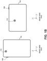
- Figure 1A illustrates the form factor of a digital camera device 100 as seen from front view 101A and side view 101B.
- Digital camera device 100 may be, for example, a mobile phone, a tablet computer, or a wearable computing device. However, other embodiments are possible.
- digital camera device 100 could further include rear-facing camera 112.
- Camera 112 may be positioned on a side of body 102 opposite front-facing camera 104.
- Rear views 101C and 101D show two alternate arrangements of rear-facing camera 112. Nonetheless, other arrangements are possible.
- digital camera device 100 may include one or multiple cameras positioned on various sides of body 102.
- Front-facing camera 104 may include an image sensor and associated optical elements such as lenses. Front-facing camera 104 may offer zoom capabilities or could have a fixed focal length. In other embodiments, interchangeable lenses could be used with front-facing camera 104. Front-facing camera 104 may have a variable mechanical aperture and a mechanical and/or electronic shutter. Front-facing camera 104 also could be configured to capture still images, video images, or both. Further, front-facing camera 104 could represent a monoscopic camera, for example.
- Rear-facing camera 112 may be an image capture component, including an aperture, lens, recording surface, and shutter.
- Either or both of front facing camera 104, and rear-facing camera 112 may include or be associated with an illumination component that provides a light field to illuminate a target object.
- an illumination component could provide flash or constant illumination of the target object.
- An illumination component could also be configured to provide a light field that includes one or more of structured light, polarized light, and light with specific spectral content. Other types of light fields known and used to recover 3D models from an object are possible within the context of the embodiments herein.
- FIG. 1 is a simplified block diagram showing some of the components of an example computing device 200 that may include camera components 224.
- computing device 200 may include a communication interface 202, a user interface 204, a processor 206, data storage 208, and camera components 224, all of which may be communicatively linked together by a system bus, network, or other connection mechanism 210.
- User interface 204 may function to allow computing device 200 to interact with a human or non-human user, such as to receive input from a user and to provide output to the user.
- user interface 204 may include input components such as a keypad, keyboard, touch-sensitive or presence-sensitive panel, computer mouse, trackball, joystick, microphone, and so on.
- User interface 204 may also include one or more output components such as a display screen which, for example, may be combined with a presence-sensitive panel. The display screen may be based on CRT, LCD, and/or LED technologies, or other technologies now known or later developed.
- User interface 204 may also be configured to generate audible output(s), via a speaker, speaker jack, audio output port, audio output device, earphones, and/or other similar devices.
- Application programs 220 may communicate with operating system 222 through one or more application programming interfaces (APIs). These APIs may facilitate, for instance, application programs 220 reading and/or writing application data 214, transmitting or receiving information via communication interface 202, receiving and/or displaying information on user interface 204, and so on.
- APIs application programming interfaces
- application programs 220 may be referred to as "apps" for short. Additionally, application programs 220 may be downloadable to computing device 200 through one or more online application stores or application markets. However, application programs can also be installed on computing device 200 in other ways, such as via a web browser or through a physical interface (e.g., a USB port) on computing device 200.
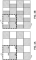
- pixel 302 of pixel block 300 is made up of green subpixels 304A, 304B along with blue subpixel 306 and red subpixel 308. These subpixels are arranged in a two subpixel by two subpixel square within pixel 302. Green subpixel 304A is shown positioned in the top left corner of pixel 302 and green subpixel 304B is shown positioned in the bottom right corner of pixel 302. Although green subpixels 304A, 304B have a diagonal arrangement within pixel 302, the subpixels can have other arrangements.
- Subpixel images determined based on data from different sets of green subpixels are further used to determine a disparity that exists between the different viewpoints represented by each subpixel image.
- the disparity represents the difference between the subpixel images.
- the disparity can arise from the difference in viewpoints represented by the subpixel images. As such, the degree of disparity between the subpixel images can vary.
- camera 402 may capture a single image of scene 400
- camera 402 may capture a series of images of scene 400 over a short duration.
- camera 402 may capture a burst of consecutive images and compare portions of the series of images to produce an aggregate image that removes some of the noise that may be captured within some of the images. Noise within images can result from the image sensor or movement of the camera during image capture.
- camera 402 may utilize a series of images of scene 400 to develop an overall image that reduces potential noise.
- camera 402 may also increase or decrease the sensitivity of the image sensor based on the amount of ambient light available.
- first subpixel image 404 is represented by a first set of subpixels from the initial image and second subpixel image 406 may be represented by a second set of subpixels from the initial image.
- first subpixel image 404 may represent data obtained from blue and red subpixels as well as a first set of green subpixels (e.g., a top row green subpixel in each pixel) in order to represent scene 400 from a first angle.
- second subpixel image 406 may represent data obtained from blue and red subpixels as well as a second set of green subpixel (e.g., a bottom row green subpixel in each pixel) to represent scene 400 from a second angle.
- the second angle and the first angle may differ due to a baseline difference in the positions between the green subpixels within each pixel.
- the first angle and second angle may differ along a horizontal axis and/or a vertical axis.
- Each pixel includes two green subpixels that are each split into two different planes of focus similar to the pixel 312 depicted in Figure 3B .
- first subpixel image 404 may represent a first focus plane of the green subpixels and second subpixel image 406 may represent a second focus plane of the green subpixels.
- Substantial alignment in this context may be an alignment in which an error factor between the pixels is minimized or determined to be below a threshold value. For instance, a least-squares error may be calculated for a number of candidate alignments, and the alignment with the lowest least squares error may be determined to be a substantial alignment.
- alignment may involve partitioning a subpixel image into a number of pixel neighborhoods (e.g., block of pixels), and each pixel neighborhood can be aligned separately according to respective individual offsets. The result might be that some blocks are offset differently than others.
- the net difference between all pixels in the translated source subpixel image and the target subpixel image may be determined and summed. This net error is stored, and the translation with the minimum error may be selected as a substantial alignment.
- Other image alignment techniques may be used in addition to or instead of those described herein.
- camera 402 may use an edge smoothing process in addition to the depth estimations when generating the new version of the image.
- the edge smoothing process may improve the disconnection between a focused upon element and blurred portions within the new version of the image. For instance, edge smoothing may be used to determine edges of an element in focus. As a result, a background behind the element in focus can be blurred up to the detected edges.
- camera 402 may determine the disparity of a portion of the scene that includes a feature with a corner. In these cases, determining the disparity between the portion of the scene as represented in the subpixel images may involve detecting the corner in each subpixel image, and warping a subpixel image to the other according to a translation. The translation may cause the corner in the subpixel images to substantially match. As a result, the disparity may be based on a pixel distance represented by the translation.
- Figure 5 depicts a simplified representation of an image capture component capturing an image of an object.
- the image capture component includes a lens 502 and a recording surface 504.
- Light representing object 500 passes through lens 502 and creates an image of object 500 on recording surface 504 (due to the optics of lens 502, the image on recording surface 504 appears upside down).
- Lens 502 may be adjustable, in that it can move left or right with respect to Figure 5 . For instance, adjustments may be made by applying a voltage to a motor (not shown in Figure 5 ) controlling the position of lens 502. The motor may move lens 502 further from or closer to recording surface 504.
- the image capture component can focus on objects at a range of distances.
- first green subpixel 602 and second green subpixel 604 have data depicting an object that is a distance z (i.e., depth) from the camera on the z-axis.
- the values of b and f are known, but the value of z is to be estimated.
- the portions focused upon and the portions blurred within modified image 710 may factor a user input originally received when capturing input image 700.
- the camera device may display the viewpoint for the potential image of the camera using a viewfinder.
- the viewfinder may be a touchscreen that enables a user to select a portion of the scene that the camera should focus upon during image capture.
- the camera device may factor the prior selection of the scene by the user when determining which element (e.g., toy dog 502) to focus upon and which elements to blur within modified image 710.
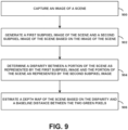
- Block 904 involves determining a disparity between a portion of the scene as represented by the first subpixel image and the portion of the scene as represented by the second subpixel image.
- aligning and averaging frames to reduce noise may require additional analysis in order to limit double images (ghosts) from appearing in the image.
- ghosts can appear within an image when the camera device is not steady during image capture or when features within the scene move during image capture.
- the additional analysis and refinement can reduce and prevent ghosts from appearing in the captured image despite aligning and averaging frames to reduce noise within the image.
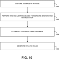
- a neural network is used to perform foreground-background segmentation on a captured image.
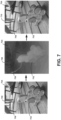
- the neural network may analyze the image in order to estimate which pixels represent a primary focus in the foreground and which pixels do not. This process may produce results similar to input image 800 and output image 804 shown in Figure 8 .
- the neural network can be trained to detect pixels that correspond to an object positioned in the foreground of the image.
- the skip connections associated with the CNN may allow information to easily flow from the early stages in the CNN process where the CNN reasons about low-level features (e.g., colors and edges) up to later stages of the CNN where the CNN reasons about high-level features (e.g., faces and body parts).
- Combining stages of processing using the CNN can identify and focus upon the desired subject of the image (e.g., focus upon the person), including identifying which pixels correspond to the desired object (e.g., which pixels correspond to the person).
- the output of a CNN analysis may be smoothed in order to more clearly differentiate between the foreground and background of the original image.
- the output may identify objects held by a person who is the main focus of the image and associate the held objects as part of the foreground.
- the results of a CNN analysis upon an image can be used to apply a uniform blurring of an entire background of the image. Although this can enhance the image, additional steps may be used to differentiate and blur objects at varying depths in the background differently.
- the above process involving looking at the scene from different halves of the image lens can produce results that resemble splitting every pixel on the image sensor into two smaller side-by-side pixels and reading them from the image sensor separately.
- some examples can involve using one or both techniques to produce a depth map.
- one process may be used to check the depth estimation determined using the other process.
- depth information for the image may be determined using only the process involving splitting the lens into two portions in order to reduce the time and resources required.
- a combination between the segmentation mask computed at block 1002 and the depth map estimated at block 1004 can be used to determine how much to blur each pixel in the original image when producing the enhanced, final image.
- focal features of the scene e.g., person in the center of the image
- pixels of features in the background of the image may be blurred in proportion based on how far each background feature is from the in-focus plane (e.g., from the camera).
- the estimated depth map can be used to estimate the distances between background features and the in-focus plane.
- each step, block, and/or communication can represent a processing of information and/or a transmission of information in accordance with example embodiments.
- Alternative embodiments are included within the scope of these example embodiments.
- functions described as steps, blocks, transmissions, communications, requests, responses, and/or messages can be executed out of order from that shown or discussed, including substantially concurrent or in reverse order, depending on the functionality involved.
- more or fewer blocks and/or functions can be used with any of the ladder diagrams, scenarios, and flow charts discussed herein, and these ladder diagrams, scenarios, and flow charts can be combined with one another, in part or in whole.
- a step or block that represents a processing of information can correspond to circuitry that can be configured to perform the specific logical functions of a herein-described method or technique.
- a step or block that represents a processing of information can correspond to a module, a segment, or a portion of program code (including related data).
- the program code can include one or more instructions executable by a processor for implementing specific logical functions or actions in the method or technique.
- the program code and/or related data can be stored on any type of computer readable medium such as a storage device including a disk, hard drive, or other storage medium.
Landscapes
- Engineering & Computer Science (AREA)
- Computer Vision & Pattern Recognition (AREA)
- Physics & Mathematics (AREA)
- General Physics & Mathematics (AREA)
- Theoretical Computer Science (AREA)
- Human Computer Interaction (AREA)
- Multimedia (AREA)
- Signal Processing (AREA)
- Studio Devices (AREA)
- Image Analysis (AREA)
Claims (15)
- Verfahren, das Folgendes umfasst:Aufnehmen eines Bildes einer Szene durch eine Kameravorrichtung (100, 200);Generieren eines ersten Subpixelbildes der Szene und eines zweiten Subpixelbildes der Szene durch die Kameravorrichtung auf Grundlage des Bildes der Szene, wobei das erste Subpixelbild durch einen ersten Satz von Subpixeln aus dem Bild dargestellt wird und das zweite Subpixelbild durch einen zweiten Satz von Subpixeln aus dem Bild dargestellt wird, wobei ein gegebenes Pixel des Bildes der Szene zwei grüne Subpixel einer geteilten Ebene beinhaltet, wobei jedes der zwei grünen Subpixel der geteilten Ebene einen jeweiligen ersten Abschnitt und einen jeweiligen zweiten Abschnitt umfasst, wobei der erste Abschnitt beider grünen Subpixel der geteilten Ebene in dem ersten Subpixelbild dargestellt wird und der zweite Abschnitt beider grünen Subpixel der geteilten Ebene in dem zweiten Subpixelbild dargestellt wird;Bestimmen einer Disparität zwischen einem Abschnitt der Szene, wie durch das erste Subpixelbild dargestellt, und dem Abschnitt der Szene, wie durch das zweite Subpixelbild dargestellt, durch die Kameravorrichtung; undSchätzen einer Tiefenkarte der Szene durch die Kameravorrichtung auf Grundlage der Disparität und eines Basisabstands zwischen den zwei grünen Subpixeln der geteilten Ebene, wobei die Tiefenkarte eine Tiefe des Abschnitts der Szene relativ zu einem oder mehreren anderen Abschnitten der Szene angibt.
- Verfahren nach Anspruch 1, wobei das Bestimmen der Disparität zwischen dem Abschnitt der Szene, wie durch das erste Subpixelbild dargestellt, und dem Abschnitt der Szene, wie durch das zweite Subpixelbild dargestellt, Folgendes umfasst:Identifizieren einer ersten Umgebung von Pixeln in dem ersten Subpixelbild;Identifizieren einer zweiten Umgebung von Pixeln in dem zweiten Subpixelbild; undVerschieben der ersten Umgebung von Pixeln oder der zweiten Umgebung von Pixeln, bis die erste Umgebung von Pixeln und die zweite Umgebung von Pixeln im Wesentlichen ausgerichtet sind, wobei die Disparität auf einem Pixelabstand basiert, der durch die Verschiebung dargestellt ist.
- Verfahren nach Anspruch 2, wobei das Verschieben der ersten Umgebung von Pixeln oder der zweiten Umgebung von Pixeln, bis die erste Umgebung von Pixeln und die zweite Umgebung von Pixeln im Wesentlichen ausgerichtet sind, Folgendes umfasst:Durchführen einer ersten Verschiebung zwischen der ersten Umgebung von Pixeln oder der zweiten Umgebung von Pixeln, um eine erste Ausrichtung zwischen der ersten Umgebung von Pixeln und der zweiten Umgebung von Pixeln zu bestimmen;Bestimmen einer Konfidenz auf Grundlage der ersten Ausrichtung zwischen der ersten Umgebung von Pixeln und der zweiten Umgebung von Pixeln; undDurchführen einer oder mehrerer nachfolgenden Verschiebungen zwischen der ersten Umgebung von Pixeln oder der zweiten Umgebung von Pixeln auf Grundlage dessen, dass die Konfidenz unter einem Schwellenkonfidenzniveau liegt, um eine nachfolgende Ausrichtung zwischen der ersten Umgebung von Pixeln und der zweiten Umgebung von Pixeln zu bestimmen, die dazu führt, dass die Konfidenz über dem Schwellenkonfidenzniveau liegt.
- Verfahren nach einem der vorhergehenden Ansprüche, wobei das Bestimmen der Disparität zwischen dem Abschnitt der Szene, wie durch das erste Subpixelbild dargestellt, und dem Abschnitt der Szene, wie durch das zweite Subpixelbild dargestellt, Folgendes umfasst:Berechnen von Fehlerwerten kleinster Quadrate einer Vielzahl von möglichen Ausrichtungen zwischen einer ersten Umgebung von Pixeln in dem ersten Subpixelbild und einer zweiten Umgebung von Pixeln in dem zweiten Subpixelbild; undBestimmen einer Ausrichtung zwischen der ersten Umgebung von Pixeln und der zweiten Umgebung von Pixeln auf Grundlage der Fehlerwerte kleinster Quadrate, sodass die erste Umgebung von Pixeln und die zweite Umgebung von Pixeln im Wesentlichen ausgerichtet sind, wobei die Disparität auf der bestimmten Ausrichtung zwischen der ersten Umgebung von Pixeln und der zweiten Umgebung von Pixeln basiert.
- Verfahren nach einem der vorhergehenden Ansprüche, ferner umfassend:Partitionieren des Bildes in eine Vielzahl von Segmenten unter Verwendung eines Bildsegmentierungsprozesses, wobei jedes Segment der Vielzahl von Segmenten einen Satz von Pixeln umfasst;Bestimmen von Segmenten der Vielzahl von Segmenten, die jeweilige Eigenschaften teilen;Identifizieren von Begrenzungen von Merkmalen in der in dem Bild abgebildeten Szene auf Grundlage von Segmenten, die jeweilige Eigenschaften teilen;Bestimmen einer oder mehrerer Begrenzungen eines Objekts in dem Abschnitt der Szene auf Grundlage der identifizierten Begrenzungen; undGenerieren einer neuen Version des Bildes mit Fokus auf das Objekt und mit einem verschwommenen Hintergrund hinter dem Objekt auf Grundlage der Tiefenkarte der Szene und der einen oder mehreren Begrenzungen des Objekts.
- Verfahren nach einem der vorhergehenden Ansprüche, ferner umfassend:Empfangen einer Eingabe an der Kameravorrichtung von einer Eingabeschnittstelle, die einen Fokusaspekt der Szene für die Kamera definiert, auf den beim Aufnehmen des Bildes zu fokussieren ist, wobei die Eingabeschnittstelle ein Touchscreen ist, der dazu konfiguriert ist, eine Ansicht der Szene aus einem Blickpunkt der Kamera anzuzeigen;wobei das Bestimmen der Disparität zwischen dem Abschnitt der Szene, wie durch das erste Subpixelbild dargestellt, und dem Abschnitt der Szene, wie durch das zweite Subpixelbild dargestellt, Folgendes umfasst:Bestimmen der Disparität zwischen einem gegebenen Abschnitt der Szene, der den Fokusaspekt beinhaltet, wie durch das erste Subpixelbild und das zweite Subpixelbild dargestellt; undwobei das Schätzen der Tiefenkarte der Szene Folgendes umfasst:
Schätzen einer Tiefe des gegebenen Abschnitts der Szene, der den Fokusaspekt beinhaltet. - Verfahren nach einem der vorhergehenden Ansprüche, wobei das Schätzen der Tiefenkarte der Szene Folgendes umfasst:
Schätzen der Tiefe des Abschnitts der Szene relativ zu dem einen oder den mehreren anderen Abschnitten der Szene unter Verwendung eines räumlichen Sensors der Kameravorrichtung. - Verfahren nach einem der vorhergehenden Ansprüche, wobei das erste Subpixelbild der Szene die Szene aus einem ersten Winkel darstellt und wobei das zweite Subpixelbild der Szene die Szene aus einem zweiten Winkel darstellt,wobei sich das erste Subpixelbild der Szene, das die Szene aus dem ersten Winkel darstellt, und das zweite Subpixelbild der Szene, das die Szene aus dem zweiten Winkel darstellt, optional entlang einer horizontalen Ebene unterscheiden,wobei sich das erste Subpixelbild der Szene, das die Szene aus dem ersten Winkel darstellt, und das zweite Subpixelbild der Szene, das die Szene aus dem zweiten Winkel darstellt, optional entlang einer vertikalen Ebene unterscheiden.
- Verfahren nach einem der vorhergehenden Ansprüche, wobei das gegebene Pixel des Bildes vier Subpixel umfasst, die in einem Quadrat von zwei Subpixel mal zwei Subpixel angeordnet sind, und wobei ein erstes grünes Subpixel an einer oberen Reihe des Quadrats von zwei Subpixel mal zwei Subpixel positioniert ist und ein zweites grünes Subpixel an einer unteren Reihe des Quadrats von zwei Subpixel mal zwei Subpixel positioniert ist, wobei das erste grüne Subpixel und das zweite grüne Pixel optional in einer diagonalen Anordnung innerhalb des Quadrats von zwei Subpixel mal zwei Subpixel des gegebenen Pixels des Bildes liegen.
- Verfahren nach einem der vorhergehenden Ansprüche, wobei das Schätzen der Tiefenkarte der Szene Folgendes umfasst:
Schätzen der Tiefe eines Satzes von Pixeln des Bildes, das den Abschnitt der Szene abbildet, relativ zu einer Tiefe einer Vielzahl von Pixeln des Bildes, das den einen oder die mehreren anderen Abschnitte der Szene abbildet. - Computerlesbares Speichermedium, das darauf gespeicherte Programmanweisungen aufweist, die bei Ausführung durch eine Kameravorrichtung (100, 200) die Kameravorrichtung dazu veranlassen, Vorgänge durchzuführen, die Folgendes umfassen:Aufnehmen eines Bildes einer Szene;Generieren eines ersten Subpixelbildes der Szene und eines zweiten Subpixelbildes der Szene auf Grundlage des Bildes der Szene, wobei das erste Subpixelbild durch einen ersten Satz von Subpixeln aus dem Bild dargestellt wird und das zweite Subpixelbild durch einen zweiten Satz von Subpixeln aus dem Bild dargestellt wird, wobei ein gegebenes Pixel des Bildes der Szene zwei grüne Subpixel einer geteilten Ebene beinhaltet, wobei jedes der zwei grünen Subpixel der geteilten Ebene einen jeweiligen ersten Abschnitt und einen jeweiligen zweiten Abschnitt umfasst, wobei der erste Abschnitt beider grünen Subpixel der geteilten Ebene in dem ersten Subpixelbild dargestellt wird und der zweite Abschnitt beider grünen Subpixel der geteilten Ebene in dem zweiten Subpixelbild dargestellt wird;Bestimmen einer Disparität zwischen einem Abschnitt der Szene, wie durch das erste Subpixelbild dargestellt, und dem Abschnitt der Szene, wie durch das zweite Subpixelbild dargestellt; undSchätzen einer Tiefenkarte der Szene auf Grundlage der Disparität und eines Basisabstands zwischen den zwei grünen Subpixeln der geteilten Ebene, wobei die Tiefenkarte eine Tiefe des Abschnitts der Szene relativ zu einem oder mehreren anderen Abschnitten der Szene angibt.
- Computerlesbares Medium nach Anspruch 11, wobei das gegebene Pixel des Bildes vier Subpixel umfasst, die in einem Quadrat von zwei Subpixel mal zwei Subpixel angeordnet sind, und wobei ein erstes grünes Subpixel an einer oberen Reihe des Quadrats von zwei Subpixel mal zwei Subpixel positioniert ist und ein zweites grünes Subpixel an einer unteren Reihe des Quadrats von zwei Subpixel mal zwei Subpixel positioniert ist.
- Computerlesbares Medium nach Anspruch 11, wobei das erste Subpixelbild der Szene die Szene aus einem ersten Winkel darstellt und wobei das zweite Subpixelbild der Szene die Szene aus einem zweiten Winkel darstellt.
- Kameravorrichtung (100, 200), die Folgendes umfasst:einen Bildsensor;einen Prozessor (206);einen Speicher; undProgrammanweisungen, die in dem Speicher gespeichert sind, die bei Ausführung durch den Prozessor die Kameravorrichtung dazu veranlassen, Vorgänge durchzuführen, die das Verfahren nach einem der Ansprüche 1 bis 10 umfassen.
- Computerprogrammprodukt, das Anweisungen umfasst, die bei Ausführung durch eine Recheneinrichtung diese dazu veranlassen, das Verfahren nach einem der Ansprüche 1 bis 10 durchzuführen.
Applications Claiming Priority (3)
| Application Number | Priority Date | Filing Date | Title |
|---|---|---|---|
| US201762567888P | 2017-10-04 | 2017-10-04 | |
| US201762572896P | 2017-10-16 | 2017-10-16 | |
| PCT/US2017/064678 WO2019070299A1 (en) | 2017-10-04 | 2017-12-05 | DEPTH ESTIMATION USING A SINGLE CAMERA |
Publications (2)
| Publication Number | Publication Date |
|---|---|
| EP3692500A1 EP3692500A1 (de) | 2020-08-12 |
| EP3692500B1 true EP3692500B1 (de) | 2025-04-16 |
Family
ID=60937861
Family Applications (1)
| Application Number | Title | Priority Date | Filing Date |
|---|---|---|---|
| EP17826003.0A Active EP3692500B1 (de) | 2017-10-04 | 2017-12-05 | Schätzen der tiefe unter verwendung einer einzigen kamera |
Country Status (5)
| Country | Link |
|---|---|
| US (1) | US11210799B2 (de) |
| EP (1) | EP3692500B1 (de) |
| JP (1) | JP7145943B2 (de) |
| CN (1) | CN111164647B (de) |
| WO (1) | WO2019070299A1 (de) |
Families Citing this family (77)
| Publication number | Priority date | Publication date | Assignee | Title |
|---|---|---|---|---|
| US8502856B2 (en) | 2010-04-07 | 2013-08-06 | Apple Inc. | In conference display adjustments |
| EP3286915B1 (de) | 2015-04-23 | 2021-12-08 | Apple Inc. | Benutzerschnittstelle für digitalen sucher für mehrere kameras |
| US9912860B2 (en) | 2016-06-12 | 2018-03-06 | Apple Inc. | User interface for camera effects |
| DK180859B1 (en) | 2017-06-04 | 2022-05-23 | Apple Inc | USER INTERFACE CAMERA EFFECTS |
| US10372298B2 (en) | 2017-09-29 | 2019-08-06 | Apple Inc. | User interface for multi-user communication session |
| WO2019100511A1 (en) * | 2017-11-22 | 2019-05-31 | Zhejiang Dahua Technology Co., Ltd. | An image processing method and system |
| US11112964B2 (en) | 2018-02-09 | 2021-09-07 | Apple Inc. | Media capture lock affordance for graphical user interface |
| CN110278366B (zh) * | 2018-03-14 | 2020-12-01 | 虹软科技股份有限公司 | 一种全景图像虚化方法、终端及计算机可读存储介质 |
| DK180130B1 (da) | 2018-05-07 | 2020-06-02 | Apple Inc. | Multi-participant live communication user interface |
| US11722764B2 (en) | 2018-05-07 | 2023-08-08 | Apple Inc. | Creative camera |
| CN108965704B (zh) * | 2018-07-19 | 2020-01-31 | 维沃移动通信有限公司 | 一种图像传感器、移动终端及图像拍摄方法 |
| JP6971934B2 (ja) * | 2018-08-10 | 2021-11-24 | 株式会社東芝 | 画像処理装置 |
| US11195257B2 (en) * | 2018-08-24 | 2021-12-07 | Canon Kabushiki Kaisha | Image processing method, image processing apparatus, imaging apparatus, lens apparatus, storage medium, and image processing system |
| WO2020041893A1 (en) * | 2018-09-01 | 2020-03-05 | Digital Animal Interactive Inc. | Image processing methods and systems |
| DK201870623A1 (en) | 2018-09-11 | 2020-04-15 | Apple Inc. | User interfaces for simulated depth effects |
| US11321857B2 (en) | 2018-09-28 | 2022-05-03 | Apple Inc. | Displaying and editing images with depth information |
| US11128792B2 (en) * | 2018-09-28 | 2021-09-21 | Apple Inc. | Capturing and displaying images with multiple focal planes |
| US11405535B2 (en) | 2019-02-28 | 2022-08-02 | Qualcomm Incorporated | Quad color filter array camera sensor configurations |
| US11094072B2 (en) * | 2019-04-09 | 2021-08-17 | Samsung Electronics Co., Ltd | System and method for providing single image depth estimation based on deep neural network |
| US11770601B2 (en) | 2019-05-06 | 2023-09-26 | Apple Inc. | User interfaces for capturing and managing visual media |
| US11706521B2 (en) | 2019-05-06 | 2023-07-18 | Apple Inc. | User interfaces for capturing and managing visual media |
| US10984513B1 (en) | 2019-09-30 | 2021-04-20 | Google Llc | Automatic generation of all-in-focus images with a mobile camera |
| CN110766732A (zh) * | 2019-10-22 | 2020-02-07 | 杭州凌像科技有限公司 | 一种鲁棒的单相机深度图估计方法 |
| US11727543B2 (en) * | 2019-11-18 | 2023-08-15 | Shinyfields Limited | Systems and methods for content-aware enhancement of images |
| US11330246B2 (en) * | 2019-11-21 | 2022-05-10 | Microsoft Technology Licensing, Llc | Imaging system configured to use time-of-flight imaging and stereo imaging |
| US11556784B2 (en) | 2019-11-22 | 2023-01-17 | Samsung Electronics Co., Ltd. | Multi-task fusion neural network architecture |
| CN114945943B (zh) * | 2020-01-13 | 2025-05-06 | 谷歌有限责任公司 | 基于虹膜大小估计深度 |
| CN113129353B (zh) * | 2020-01-16 | 2025-10-17 | 北京三星通信技术研究有限公司 | 深度估计方法和装置 |
| US11663728B2 (en) | 2020-01-16 | 2023-05-30 | Samsung Electronics Co., Ltd. | Depth estimation method and apparatus |
| KR102905974B1 (ko) * | 2020-01-23 | 2025-12-29 | 삼성전자 주식회사 | 복수의 공유 픽셀들을 포함하는 이미지 장치 및 이의 동작 방법 |
| CN115066881B (zh) * | 2020-02-06 | 2023-11-14 | Oppo广东移动通信有限公司 | 对于图像序列生成稳定化图像合成效果的方法、系统及计算机可读介质 |
| CN111385481A (zh) * | 2020-03-30 | 2020-07-07 | 北京达佳互联信息技术有限公司 | 图像处理方法及装置、电子设备及存储介质 |
| US11079913B1 (en) | 2020-05-11 | 2021-08-03 | Apple Inc. | User interface for status indicators |
| JP7521259B2 (ja) * | 2020-05-27 | 2024-07-24 | ブラザー工業株式会社 | 学習済みの機械学習モデル、画像処理装置、および、機械学習モデルのトレーニング方法 |
| US11054973B1 (en) | 2020-06-01 | 2021-07-06 | Apple Inc. | User interfaces for managing media |
| CN111814659B (zh) * | 2020-07-07 | 2024-03-29 | 杭州海康威视数字技术股份有限公司 | 一种活体检测方法、和系统 |
| US11212449B1 (en) | 2020-09-25 | 2021-12-28 | Apple Inc. | User interfaces for media capture and management |
| CN112164017B (zh) * | 2020-09-27 | 2023-11-17 | 中国兵器工业集团第二一四研究所苏州研发中心 | 一种基于深度学习的偏振彩色化方法 |
| US11223780B1 (en) * | 2020-10-23 | 2022-01-11 | Black Sesame Technologies Inc. | Two-stage method to merge burst image frames |
| US12008738B2 (en) * | 2020-11-13 | 2024-06-11 | Google Llc | Defocus blur removal and depth estimation using dual-pixel image data |
| US12413701B2 (en) | 2020-11-25 | 2025-09-09 | Qualcomm Incorporated | Foldable electronic device for multi-view image capture |
| US11496728B2 (en) | 2020-12-15 | 2022-11-08 | Waymo Llc | Aperture health monitoring mode |
| US11431891B2 (en) | 2021-01-31 | 2022-08-30 | Apple Inc. | User interfaces for wide angle video conference |
| US12301979B2 (en) | 2021-01-31 | 2025-05-13 | Apple Inc. | User interfaces for wide angle video conference |
| CN115244570B (zh) * | 2021-02-24 | 2025-11-14 | 谷歌有限责任公司 | 合并分离像素数据以获得更深景深 |
| US12170579B2 (en) | 2021-03-05 | 2024-12-17 | Apple Inc. | User interfaces for multi-participant live communication |
| US12254644B2 (en) | 2021-03-31 | 2025-03-18 | Leica Camera Ag | Imaging system and method |
| US11893668B2 (en) | 2021-03-31 | 2024-02-06 | Leica Camera Ag | Imaging system and method for generating a final digital image via applying a profile to image information |
| US11778339B2 (en) | 2021-04-30 | 2023-10-03 | Apple Inc. | User interfaces for altering visual media |
| US11539876B2 (en) | 2021-04-30 | 2022-12-27 | Apple Inc. | User interfaces for altering visual media |
| US11893214B2 (en) | 2021-05-15 | 2024-02-06 | Apple Inc. | Real-time communication user interface |
| US11907605B2 (en) | 2021-05-15 | 2024-02-20 | Apple Inc. | Shared-content session user interfaces |
| CN120881039A (zh) | 2021-05-15 | 2025-10-31 | 苹果公司 | 实时通信用户界面 |
| US11822761B2 (en) | 2021-05-15 | 2023-11-21 | Apple Inc. | Shared-content session user interfaces |
| US12449961B2 (en) | 2021-05-18 | 2025-10-21 | Apple Inc. | Adaptive video conference user interfaces |
| US12112024B2 (en) | 2021-06-01 | 2024-10-08 | Apple Inc. | User interfaces for managing media styles |
| US12205249B2 (en) | 2021-06-09 | 2025-01-21 | Apple Inc. | Intelligent portrait photography enhancement system |
| CN115917598B (zh) * | 2021-07-02 | 2026-03-17 | 谷歌有限责任公司 | 用于确定视频中的移动对象的一致深度的模型 |
| US11303800B1 (en) * | 2021-07-13 | 2022-04-12 | Shenzhen GOODIX Technology Co., Ltd. | Real-time disparity upsampling for phase detection autofocus in digital imaging systems |
| CN117716700A (zh) * | 2021-08-23 | 2024-03-15 | 三星电子株式会社 | 场景自动聚焦的方法及电子装置 |
| US12368946B2 (en) | 2021-09-24 | 2025-07-22 | Apple Inc. | Wide angle video conference |
| US11770600B2 (en) | 2021-09-24 | 2023-09-26 | Apple Inc. | Wide angle video conference |
| US12267622B2 (en) | 2021-09-24 | 2025-04-01 | Apple Inc. | Wide angle video conference |
| US12316946B2 (en) * | 2021-11-19 | 2025-05-27 | Motorola Solutions, Inc. | Method, system and computer program product for divided processing in providing object detection focus |
| US12506953B2 (en) | 2021-12-03 | 2025-12-23 | Apple Inc. | Device, methods, and graphical user interfaces for capturing and displaying media |
| US20230188691A1 (en) * | 2021-12-14 | 2023-06-15 | Robert John Hergert | Active dual pixel stereo system for depth extraction |
| WO2023154431A1 (en) * | 2022-02-11 | 2023-08-17 | Canon U.S.A., Inc. | Apparatus and method for generating depth maps from raw dual pixel sensor data |
| EP4285345A1 (de) * | 2022-04-01 | 2023-12-06 | Google LLC | Korrelationsbasierte objektanti-spoofing für doppelpixel-kameras |
| US12563299B2 (en) | 2022-04-04 | 2026-02-24 | Apple Inc. | User interfaces for camera sharing |
| US12277696B2 (en) * | 2022-04-08 | 2025-04-15 | Robert Bosch Gmbh | Data augmentation for domain generalization |
| FR3135811B1 (fr) * | 2022-05-17 | 2025-02-14 | Safran | Dispositif et procédé d'aide à la navigation basé sur l'imagerie monoculaire |
| US12578837B2 (en) | 2022-09-23 | 2026-03-17 | Apple Inc. | User interfaces for managing sharing of content in three-dimensional environments |
| DE102022125838A1 (de) * | 2022-10-06 | 2024-04-11 | Arnold & Richter Cine Technik Gmbh & Co. Betriebs Kg | Bildsensor |
| CN115294187B (zh) * | 2022-10-08 | 2023-01-31 | 合肥的卢深视科技有限公司 | 深度相机的图像处理方法、电子设备及存储介质 |
| US12530790B2 (en) | 2023-06-21 | 2026-01-20 | Samsung Electronics Co., Ltd. | Hardware-efficient disparity estimation using the DCT of interleaved images |
| CN117934301A (zh) * | 2024-01-07 | 2024-04-26 | Oppo广东移动通信有限公司 | 图像处理方法、装置、电子设备和计算机可读存储介质 |
| US20250238129A1 (en) | 2024-01-18 | 2025-07-24 | Apple Inc. | User interfaces integrating hardware buttons |
Citations (2)
| Publication number | Priority date | Publication date | Assignee | Title |
|---|---|---|---|---|
| US20150086127A1 (en) * | 2013-09-20 | 2015-03-26 | Samsung Electronics Co., Ltd | Method and image capturing device for generating artificially defocused blurred image |
| US20170094153A1 (en) * | 2015-07-02 | 2017-03-30 | Pixart Imaging Inc. | Distance measurement device based on phase difference and distance measurement method thereof |
Family Cites Families (13)
| Publication number | Priority date | Publication date | Assignee | Title |
|---|---|---|---|---|
| AUPQ289099A0 (en) * | 1999-09-16 | 1999-10-07 | Silverbrook Research Pty Ltd | Method and apparatus for manipulating a bayer image |
| US7911513B2 (en) | 2007-04-20 | 2011-03-22 | General Instrument Corporation | Simulating short depth of field to maximize privacy in videotelephony |
| US8866920B2 (en) * | 2008-05-20 | 2014-10-21 | Pelican Imaging Corporation | Capturing and processing of images using monolithic camera array with heterogeneous imagers |
| JP5421207B2 (ja) | 2010-08-25 | 2014-02-19 | 株式会社東芝 | 固体撮像装置 |
| US9412206B2 (en) * | 2012-02-21 | 2016-08-09 | Pelican Imaging Corporation | Systems and methods for the manipulation of captured light field image data |
| US20130287093A1 (en) * | 2012-04-25 | 2013-10-31 | Nokia Corporation | Method and apparatus for video coding |
| CN104350735B (zh) | 2012-05-28 | 2016-04-13 | 富士胶片株式会社 | 图像处理装置、摄像装置、图像处理方法 |
| IN2013MN02138A (de) * | 2012-08-07 | 2015-06-12 | Spreadtrum Comm Shanghai Co | |
| US9519972B2 (en) * | 2013-03-13 | 2016-12-13 | Kip Peli P1 Lp | Systems and methods for synthesizing images from image data captured by an array camera using restricted depth of field depth maps in which depth estimation precision varies |
| EP3284061B1 (de) * | 2015-04-17 | 2021-11-10 | FotoNation Limited | Systeme und verfahren zur durchführung einer hochgeschwindigkeitsvideoerfassung und -tiefenschätzung mit array-kameras |
| US9736366B1 (en) * | 2015-05-23 | 2017-08-15 | Google Inc. | Tile-based digital image correspondence |
| JP2017022624A (ja) | 2015-07-13 | 2017-01-26 | キヤノン株式会社 | 撮像素子及びその駆動方法、及び撮像装置 |
| US9848118B2 (en) * | 2016-03-11 | 2017-12-19 | Intel Corporation | Phase detection autofocus using opposing filter masks |
-
2017
- 2017-12-05 CN CN201780095594.0A patent/CN111164647B/zh active Active
- 2017-12-05 EP EP17826003.0A patent/EP3692500B1/de active Active
- 2017-12-05 WO PCT/US2017/064678 patent/WO2019070299A1/en not_active Ceased
- 2017-12-05 JP JP2020519252A patent/JP7145943B2/ja active Active
- 2017-12-05 US US16/652,568 patent/US11210799B2/en active Active
Patent Citations (2)
| Publication number | Priority date | Publication date | Assignee | Title |
|---|---|---|---|---|
| US20150086127A1 (en) * | 2013-09-20 | 2015-03-26 | Samsung Electronics Co., Ltd | Method and image capturing device for generating artificially defocused blurred image |
| US20170094153A1 (en) * | 2015-07-02 | 2017-03-30 | Pixart Imaging Inc. | Distance measurement device based on phase difference and distance measurement method thereof |
Also Published As
| Publication number | Publication date |
|---|---|
| CN111164647A (zh) | 2020-05-15 |
| JP7145943B2 (ja) | 2022-10-03 |
| JP2020536327A (ja) | 2020-12-10 |
| US11210799B2 (en) | 2021-12-28 |
| US20200242788A1 (en) | 2020-07-30 |
| EP3692500A1 (de) | 2020-08-12 |
| WO2019070299A1 (en) | 2019-04-11 |
| CN111164647B (zh) | 2024-05-03 |
Similar Documents
| Publication | Publication Date | Title |
|---|---|---|
| EP3692500B1 (de) | Schätzen der tiefe unter verwendung einer einzigen kamera | |
| US12579669B2 (en) | Estimating depth based on iris size | |
| US9918065B2 (en) | Depth-assisted focus in multi-camera systems | |
| US9544574B2 (en) | Selecting camera pairs for stereoscopic imaging | |
| JP7186672B2 (ja) | マルチスコピック雑音削減およびハイ・ダイナミック・レンジのためのシステムおよび方法 | |
| US9615012B2 (en) | Using a second camera to adjust settings of first camera | |
| US9154697B2 (en) | Camera selection based on occlusion of field of view | |
| US9639945B2 (en) | Depth-based application of image effects | |
| US9117134B1 (en) | Image merging with blending | |
| WO2014190051A1 (en) | Simulating high dynamic range imaging with virtual long-exposure images | |
| WO2014165472A1 (en) | Camera obstruction detection | |
| US20170171456A1 (en) | Stereo Autofocus | |
| CN115244570B (zh) | 合并分离像素数据以获得更深景深 | |
| JP2017182668A (ja) | データ処理装置、撮像装置、及びデータ処理方法 | |
| US20260129298A1 (en) | Field of View Correction Techniques for Shutterless Camera Systems | |
| WO2024076363A1 (en) | Field of view correction techniques for shutterless camera systems |
Legal Events
| Date | Code | Title | Description |
|---|---|---|---|
| STAA | Information on the status of an ep patent application or granted ep patent |
Free format text: STATUS: UNKNOWN |
|
| STAA | Information on the status of an ep patent application or granted ep patent |
Free format text: STATUS: THE INTERNATIONAL PUBLICATION HAS BEEN MADE |
|
| PUAI | Public reference made under article 153(3) epc to a published international application that has entered the european phase |
Free format text: ORIGINAL CODE: 0009012 |
|
| STAA | Information on the status of an ep patent application or granted ep patent |
Free format text: STATUS: REQUEST FOR EXAMINATION WAS MADE |
|
| 17P | Request for examination filed |
Effective date: 20200324 |
|
| AK | Designated contracting states |
Kind code of ref document: A1 Designated state(s): AL AT BE BG CH CY CZ DE DK EE ES FI FR GB GR HR HU IE IS IT LI LT LU LV MC MK MT NL NO PL PT RO RS SE SI SK SM TR |
|
| AX | Request for extension of the european patent |
Extension state: BA ME |
|
| DAV | Request for validation of the european patent (deleted) | ||
| DAX | Request for extension of the european patent (deleted) | ||
| STAA | Information on the status of an ep patent application or granted ep patent |
Free format text: STATUS: EXAMINATION IS IN PROGRESS |
|
| 17Q | First examination report despatched |
Effective date: 20210210 |
|
| GRAP | Despatch of communication of intention to grant a patent |
Free format text: ORIGINAL CODE: EPIDOSNIGR1 |
|
| STAA | Information on the status of an ep patent application or granted ep patent |
Free format text: STATUS: GRANT OF PATENT IS INTENDED |
|
| INTG | Intention to grant announced |
Effective date: 20250124 |
|
| GRAS | Grant fee paid |
Free format text: ORIGINAL CODE: EPIDOSNIGR3 |
|
| GRAA | (expected) grant |
Free format text: ORIGINAL CODE: 0009210 |
|
| STAA | Information on the status of an ep patent application or granted ep patent |
Free format text: STATUS: THE PATENT HAS BEEN GRANTED |
|
| AK | Designated contracting states |
Kind code of ref document: B1 Designated state(s): AL AT BE BG CH CY CZ DE DK EE ES FI FR GB GR HR HU IE IS IT LI LT LU LV MC MK MT NL NO PL PT RO RS SE SI SK SM TR |
|
| P01 | Opt-out of the competence of the unified patent court (upc) registered |
Free format text: CASE NUMBER: APP_12072/2025 Effective date: 20250312 |
|
| REG | Reference to a national code |
Ref country code: GB Ref legal event code: FG4D |
|
| REG | Reference to a national code |
Ref country code: CH Ref legal event code: EP |
|
| REG | Reference to a national code |
Ref country code: IE Ref legal event code: FG4D |
|
| REG | Reference to a national code |
Ref country code: DE Ref legal event code: R096 Ref document number: 602017088968 Country of ref document: DE |
|
| REG | Reference to a national code |
Ref country code: NL Ref legal event code: MP Effective date: 20250416 |
|
| PG25 | Lapsed in a contracting state [announced via postgrant information from national office to epo] |
Ref country code: NL Free format text: LAPSE BECAUSE OF FAILURE TO SUBMIT A TRANSLATION OF THE DESCRIPTION OR TO PAY THE FEE WITHIN THE PRESCRIBED TIME-LIMIT Effective date: 20250416 |
|
| REG | Reference to a national code |
Ref country code: AT Ref legal event code: MK05 Ref document number: 1786294 Country of ref document: AT Kind code of ref document: T Effective date: 20250416 |
|
| PG25 | Lapsed in a contracting state [announced via postgrant information from national office to epo] |
Ref country code: ES Free format text: LAPSE BECAUSE OF FAILURE TO SUBMIT A TRANSLATION OF THE DESCRIPTION OR TO PAY THE FEE WITHIN THE PRESCRIBED TIME-LIMIT Effective date: 20250416 Ref country code: FI Free format text: LAPSE BECAUSE OF FAILURE TO SUBMIT A TRANSLATION OF THE DESCRIPTION OR TO PAY THE FEE WITHIN THE PRESCRIBED TIME-LIMIT Effective date: 20250416 Ref country code: PT Free format text: LAPSE BECAUSE OF FAILURE TO SUBMIT A TRANSLATION OF THE DESCRIPTION OR TO PAY THE FEE WITHIN THE PRESCRIBED TIME-LIMIT Effective date: 20250818 |
|
| REG | Reference to a national code |
Ref country code: LT Ref legal event code: MG9D |
|
| PG25 | Lapsed in a contracting state [announced via postgrant information from national office to epo] |
Ref country code: NO Free format text: LAPSE BECAUSE OF FAILURE TO SUBMIT A TRANSLATION OF THE DESCRIPTION OR TO PAY THE FEE WITHIN THE PRESCRIBED TIME-LIMIT Effective date: 20250716 Ref country code: GR Free format text: LAPSE BECAUSE OF FAILURE TO SUBMIT A TRANSLATION OF THE DESCRIPTION OR TO PAY THE FEE WITHIN THE PRESCRIBED TIME-LIMIT Effective date: 20250717 |
|
| PG25 | Lapsed in a contracting state [announced via postgrant information from national office to epo] |
Ref country code: PL Free format text: LAPSE BECAUSE OF FAILURE TO SUBMIT A TRANSLATION OF THE DESCRIPTION OR TO PAY THE FEE WITHIN THE PRESCRIBED TIME-LIMIT Effective date: 20250416 |
|
| PG25 | Lapsed in a contracting state [announced via postgrant information from national office to epo] |
Ref country code: BG Free format text: LAPSE BECAUSE OF FAILURE TO SUBMIT A TRANSLATION OF THE DESCRIPTION OR TO PAY THE FEE WITHIN THE PRESCRIBED TIME-LIMIT Effective date: 20250416 |
|
| PG25 | Lapsed in a contracting state [announced via postgrant information from national office to epo] |
Ref country code: HR Free format text: LAPSE BECAUSE OF FAILURE TO SUBMIT A TRANSLATION OF THE DESCRIPTION OR TO PAY THE FEE WITHIN THE PRESCRIBED TIME-LIMIT Effective date: 20250416 |
|
| PG25 | Lapsed in a contracting state [announced via postgrant information from national office to epo] |
Ref country code: AT Free format text: LAPSE BECAUSE OF FAILURE TO SUBMIT A TRANSLATION OF THE DESCRIPTION OR TO PAY THE FEE WITHIN THE PRESCRIBED TIME-LIMIT Effective date: 20250416 |
|
| PG25 | Lapsed in a contracting state [announced via postgrant information from national office to epo] |
Ref country code: RS Free format text: LAPSE BECAUSE OF FAILURE TO SUBMIT A TRANSLATION OF THE DESCRIPTION OR TO PAY THE FEE WITHIN THE PRESCRIBED TIME-LIMIT Effective date: 20250716 |
|
| PG25 | Lapsed in a contracting state [announced via postgrant information from national office to epo] |
Ref country code: IS Free format text: LAPSE BECAUSE OF FAILURE TO SUBMIT A TRANSLATION OF THE DESCRIPTION OR TO PAY THE FEE WITHIN THE PRESCRIBED TIME-LIMIT Effective date: 20250816 |
|
| PG25 | Lapsed in a contracting state [announced via postgrant information from national office to epo] |
Ref country code: LV Free format text: LAPSE BECAUSE OF FAILURE TO SUBMIT A TRANSLATION OF THE DESCRIPTION OR TO PAY THE FEE WITHIN THE PRESCRIBED TIME-LIMIT Effective date: 20250416 |
|
| PGFP | Annual fee paid to national office [announced via postgrant information from national office to epo] |
Ref country code: GB Payment date: 20251229 Year of fee payment: 9 |
|
| PG25 | Lapsed in a contracting state [announced via postgrant information from national office to epo] |
Ref country code: DK Free format text: LAPSE BECAUSE OF FAILURE TO SUBMIT A TRANSLATION OF THE DESCRIPTION OR TO PAY THE FEE WITHIN THE PRESCRIBED TIME-LIMIT Effective date: 20250416 Ref country code: SM Free format text: LAPSE BECAUSE OF FAILURE TO SUBMIT A TRANSLATION OF THE DESCRIPTION OR TO PAY THE FEE WITHIN THE PRESCRIBED TIME-LIMIT Effective date: 20250416 |
|
| PGFP | Annual fee paid to national office [announced via postgrant information from national office to epo] |
Ref country code: FR Payment date: 20251226 Year of fee payment: 9 |
|
| REG | Reference to a national code |
Ref country code: DE Ref legal event code: R097 Ref document number: 602017088968 Country of ref document: DE |
|
| PG25 | Lapsed in a contracting state [announced via postgrant information from national office to epo] |
Ref country code: CZ Free format text: LAPSE BECAUSE OF FAILURE TO SUBMIT A TRANSLATION OF THE DESCRIPTION OR TO PAY THE FEE WITHIN THE PRESCRIBED TIME-LIMIT Effective date: 20250416 |
|
| PG25 | Lapsed in a contracting state [announced via postgrant information from national office to epo] |
Ref country code: EE Free format text: LAPSE BECAUSE OF FAILURE TO SUBMIT A TRANSLATION OF THE DESCRIPTION OR TO PAY THE FEE WITHIN THE PRESCRIBED TIME-LIMIT Effective date: 20250416 |
|
| PG25 | Lapsed in a contracting state [announced via postgrant information from national office to epo] |
Ref country code: SK Free format text: LAPSE BECAUSE OF FAILURE TO SUBMIT A TRANSLATION OF THE DESCRIPTION OR TO PAY THE FEE WITHIN THE PRESCRIBED TIME-LIMIT Effective date: 20250416 Ref country code: RO Free format text: LAPSE BECAUSE OF FAILURE TO SUBMIT A TRANSLATION OF THE DESCRIPTION OR TO PAY THE FEE WITHIN THE PRESCRIBED TIME-LIMIT Effective date: 20250416 |
|
| PG25 | Lapsed in a contracting state [announced via postgrant information from national office to epo] |
Ref country code: IT Free format text: LAPSE BECAUSE OF FAILURE TO SUBMIT A TRANSLATION OF THE DESCRIPTION OR TO PAY THE FEE WITHIN THE PRESCRIBED TIME-LIMIT Effective date: 20250416 |
|
| PLBE | No opposition filed within time limit |
Free format text: ORIGINAL CODE: 0009261 |
|
| STAA | Information on the status of an ep patent application or granted ep patent |
Free format text: STATUS: NO OPPOSITION FILED WITHIN TIME LIMIT |
|
| REG | Reference to a national code |
Ref country code: CH Ref legal event code: L10 Free format text: ST27 STATUS EVENT CODE: U-0-0-L10-L00 (AS PROVIDED BY THE NATIONAL OFFICE) Effective date: 20260225 |
|
| 26N | No opposition filed |
Effective date: 20260119 |
|
| PGFP | Annual fee paid to national office [announced via postgrant information from national office to epo] |
Ref country code: DE Payment date: 20251229 Year of fee payment: 9 |