EP3692425B1 - Method for monitoring an automation system - Google Patents
Method for monitoring an automation system Download PDFInfo
- Publication number
- EP3692425B1 EP3692425B1 EP18769334.6A EP18769334A EP3692425B1 EP 3692425 B1 EP3692425 B1 EP 3692425B1 EP 18769334 A EP18769334 A EP 18769334A EP 3692425 B1 EP3692425 B1 EP 3692425B1
- Authority
- EP
- European Patent Office
- Prior art keywords
- persons
- stay
- data
- measuring point
- evaluation
- Prior art date
- Legal status (The legal status is an assumption and is not a legal conclusion. Google has not performed a legal analysis and makes no representation as to the accuracy of the status listed.)
- Active
Links
Images
Classifications
-
- G—PHYSICS
- G05—CONTROLLING; REGULATING
- G05B—CONTROL OR REGULATING SYSTEMS IN GENERAL; FUNCTIONAL ELEMENTS OF SUCH SYSTEMS; MONITORING OR TESTING ARRANGEMENTS FOR SUCH SYSTEMS OR ELEMENTS
- G05B19/00—Program-control systems
- G05B19/02—Program-control systems electric
- G05B19/418—Total factory control, i.e. centrally controlling a plurality of machines, e.g. direct or distributed numerical control [DNC], flexible manufacturing systems [FMS], integrated manufacturing systems [IMS] or computer integrated manufacturing [CIM]
- G05B19/4184—Total factory control, i.e. centrally controlling a plurality of machines, e.g. direct or distributed numerical control [DNC], flexible manufacturing systems [FMS], integrated manufacturing systems [IMS] or computer integrated manufacturing [CIM] characterised by fault tolerance, reliability of production system
-
- G—PHYSICS
- G05—CONTROLLING; REGULATING
- G05B—CONTROL OR REGULATING SYSTEMS IN GENERAL; FUNCTIONAL ELEMENTS OF SUCH SYSTEMS; MONITORING OR TESTING ARRANGEMENTS FOR SUCH SYSTEMS OR ELEMENTS
- G05B19/00—Program-control systems
- G05B19/02—Program-control systems electric
- G05B19/418—Total factory control, i.e. centrally controlling a plurality of machines, e.g. direct or distributed numerical control [DNC], flexible manufacturing systems [FMS], integrated manufacturing systems [IMS] or computer integrated manufacturing [CIM]
- G05B19/4183—Total factory control, i.e. centrally controlling a plurality of machines, e.g. direct or distributed numerical control [DNC], flexible manufacturing systems [FMS], integrated manufacturing systems [IMS] or computer integrated manufacturing [CIM] characterised by data acquisition, e.g. workpiece identification
-
- G—PHYSICS
- G05—CONTROLLING; REGULATING
- G05B—CONTROL OR REGULATING SYSTEMS IN GENERAL; FUNCTIONAL ELEMENTS OF SUCH SYSTEMS; MONITORING OR TESTING ARRANGEMENTS FOR SUCH SYSTEMS OR ELEMENTS
- G05B19/00—Program-control systems
- G05B19/02—Program-control systems electric
- G05B19/418—Total factory control, i.e. centrally controlling a plurality of machines, e.g. direct or distributed numerical control [DNC], flexible manufacturing systems [FMS], integrated manufacturing systems [IMS] or computer integrated manufacturing [CIM]
- G05B19/41845—Total factory control, i.e. centrally controlling a plurality of machines, e.g. direct or distributed numerical control [DNC], flexible manufacturing systems [FMS], integrated manufacturing systems [IMS] or computer integrated manufacturing [CIM] characterised by system universality, reconfigurability, modularity
-
- G—PHYSICS
- G05—CONTROLLING; REGULATING
- G05B—CONTROL OR REGULATING SYSTEMS IN GENERAL; FUNCTIONAL ELEMENTS OF SUCH SYSTEMS; MONITORING OR TESTING ARRANGEMENTS FOR SUCH SYSTEMS OR ELEMENTS
- G05B19/00—Program-control systems
- G05B19/02—Program-control systems electric
- G05B19/418—Total factory control, i.e. centrally controlling a plurality of machines, e.g. direct or distributed numerical control [DNC], flexible manufacturing systems [FMS], integrated manufacturing systems [IMS] or computer integrated manufacturing [CIM]
- G05B19/41865—Total factory control, i.e. centrally controlling a plurality of machines, e.g. direct or distributed numerical control [DNC], flexible manufacturing systems [FMS], integrated manufacturing systems [IMS] or computer integrated manufacturing [CIM] characterised by job scheduling, process planning, material flow
-
- G—PHYSICS
- G06—COMPUTING OR CALCULATING; COUNTING
- G06F—ELECTRIC DIGITAL DATA PROCESSING
- G06F16/00—Information retrieval; Database structures therefor; File system structures therefor
- G06F16/90—Details of database functions independent of the retrieved data types
- G06F16/901—Indexing; Data structures therefor; Storage structures
-
- G—PHYSICS
- G06—COMPUTING OR CALCULATING; COUNTING
- G06Q—INFORMATION AND COMMUNICATION TECHNOLOGY [ICT] SPECIALLY ADAPTED FOR ADMINISTRATIVE, COMMERCIAL, FINANCIAL, MANAGERIAL OR SUPERVISORY PURPOSES; SYSTEMS OR METHODS SPECIALLY ADAPTED FOR ADMINISTRATIVE, COMMERCIAL, FINANCIAL, MANAGERIAL OR SUPERVISORY PURPOSES, NOT OTHERWISE PROVIDED FOR
- G06Q10/00—Administration; Management
- G06Q10/06—Resources, workflows, human or project management; Enterprise or organisation planning; Enterprise or organisation modelling
- G06Q10/063—Operations research, analysis or management
- G06Q10/0637—Strategic management or analysis, e.g. setting a goal or target of an organisation; Planning actions based on goals; Analysis or evaluation of effectiveness of goals
-
- G—PHYSICS
- G06—COMPUTING OR CALCULATING; COUNTING
- G06Q—INFORMATION AND COMMUNICATION TECHNOLOGY [ICT] SPECIALLY ADAPTED FOR ADMINISTRATIVE, COMMERCIAL, FINANCIAL, MANAGERIAL OR SUPERVISORY PURPOSES; SYSTEMS OR METHODS SPECIALLY ADAPTED FOR ADMINISTRATIVE, COMMERCIAL, FINANCIAL, MANAGERIAL OR SUPERVISORY PURPOSES, NOT OTHERWISE PROVIDED FOR
- G06Q50/00—Information and communication technology [ICT] specially adapted for implementation of business processes of specific business sectors, e.g. utilities or tourism
- G06Q50/04—Manufacturing
-
- G—PHYSICS
- G05—CONTROLLING; REGULATING
- G05B—CONTROL OR REGULATING SYSTEMS IN GENERAL; FUNCTIONAL ELEMENTS OF SUCH SYSTEMS; MONITORING OR TESTING ARRANGEMENTS FOR SUCH SYSTEMS OR ELEMENTS
- G05B2219/00—Program-control systems
- G05B2219/20—Pc systems
- G05B2219/24—Pc safety
- G05B2219/24001—Maintenance, repair
-
- G—PHYSICS
- G05—CONTROLLING; REGULATING
- G05B—CONTROL OR REGULATING SYSTEMS IN GENERAL; FUNCTIONAL ELEMENTS OF SUCH SYSTEMS; MONITORING OR TESTING ARRANGEMENTS FOR SUCH SYSTEMS OR ELEMENTS
- G05B2219/00—Program-control systems
- G05B2219/20—Pc systems
- G05B2219/24—Pc safety
- G05B2219/24055—Trace, store a working, operation history
-
- Y—GENERAL TAGGING OF NEW TECHNOLOGICAL DEVELOPMENTS; GENERAL TAGGING OF CROSS-SECTIONAL TECHNOLOGIES SPANNING OVER SEVERAL SECTIONS OF THE IPC; TECHNICAL SUBJECTS COVERED BY FORMER USPC CROSS-REFERENCE ART COLLECTIONS [XRACs] AND DIGESTS
- Y02—TECHNOLOGIES OR APPLICATIONS FOR MITIGATION OR ADAPTATION AGAINST CLIMATE CHANGE
- Y02P—CLIMATE CHANGE MITIGATION TECHNOLOGIES IN THE PRODUCTION OR PROCESSING OF GOODS
- Y02P90/00—Enabling technologies with a potential contribution to greenhouse gas [GHG] emissions mitigation
- Y02P90/02—Total factory control, e.g. smart factories, flexible manufacturing systems [FMS] or integrated manufacturing systems [IMS]
-
- Y—GENERAL TAGGING OF NEW TECHNOLOGICAL DEVELOPMENTS; GENERAL TAGGING OF CROSS-SECTIONAL TECHNOLOGIES SPANNING OVER SEVERAL SECTIONS OF THE IPC; TECHNICAL SUBJECTS COVERED BY FORMER USPC CROSS-REFERENCE ART COLLECTIONS [XRACs] AND DIGESTS
- Y02—TECHNOLOGIES OR APPLICATIONS FOR MITIGATION OR ADAPTATION AGAINST CLIMATE CHANGE
- Y02P—CLIMATE CHANGE MITIGATION TECHNOLOGIES IN THE PRODUCTION OR PROCESSING OF GOODS
- Y02P90/00—Enabling technologies with a potential contribution to greenhouse gas [GHG] emissions mitigation
- Y02P90/30—Computing systems specially adapted for manufacturing
Definitions
- the invention relates to a method for monitoring a process automation system, wherein a plurality of measuring points are provided in the system.
- Field devices that are used in industrial plants are already known from the state of the art. Field devices are often used in automation technology as well as in production automation. Field devices are basically all devices that are used close to the process and that provide or process process-relevant information. Field devices are used to record and/or influence process variables. Sensor systems are used to record process variables. These are used, for example, for pressure and temperature measurement, conductivity measurement, flow measurement, pH measurement, level measurement, etc. and record the corresponding process variables pressure, temperature, conductivity, pH value, level, flow, etc. Actuator systems are used to influence process variables. These are, for example, pumps or valves that can influence the flow of a liquid in a pipe or the level in a container. In addition to the measuring devices and actuators mentioned above, field devices also include remote I/Os, radio adapters or general devices that are arranged at the field level.
- field devices are usually connected to higher-level units via communication networks such as field buses (Profibus ® , Foundation ® Fieldbus, HART ® , etc.).
- the higher-level units are control units such as a PLC (programmable logic controller).
- the higher-level units are used, among other things, for process control and for commissioning the field devices.
- the measured values recorded by the field devices, in particular by sensors, are transmitted via the respective bus system to one (or
- the measured values are transmitted to (if necessary, several) higher-level units, which may further process the measured values and forward them to the system's control center.
- the control center is used for process visualization, process monitoring and process control via the higher-level units.
- data transmission from the higher-level unit to the field devices via the bus system is also required, in particular for the configuration and parameterization of field devices and for controlling actuators.
- the data generated by the field devices is often collected directly from the field using so-called data conversion units, which are referred to as “edge devices” or “cloud gateways”, for example, and automatically transmitted to a central cloud-enabled database on which an application is located.
- This application which offers functions for visualizing and further processing the data stored in the database, can be accessed by a user via the Internet.
- the US 2015/294483 A1 and the EN 10 2014 106211 A1 disclose methods for controlling access to regulated areas, which include, inter alia, a camera for monitoring persons.
- the WO 2016/030517 A1 discloses a service and information system for buildings as well as corresponding procedures for the automatic processing of technical faults or service and maintenance work and their documentation. With the help of the system, residents or users of a building can be automatically informed about repair and maintenance work that needs to be carried out.
- the invention is based on the object of presenting a method which allows the cause of an error in a process automation system to be determined quickly and reliably.
- the great advantage of the method according to the invention is that in order to find the cause of the error at measuring points in the system, information that cannot be measured by field devices and control units is also obtained. Specifically, the locations and times of people in the system are recorded and evaluated. For example, measured values from a flow meter that are outside a defined standard interval could be explained by a pipe being blocked, for example. The cause can be determined from the location data. For example, it could be evident that a maintenance mechanic is at the measuring point at regular intervals - for example to knock on the pipe with an object, which removes buildup inside the pipe. The location data makes it clear that the maintenance mechanic had not been at the measuring point for a long time before the error occurred, which meant that the buildup inside the pipe was no longer removed.
- the method can also be used in older, purely analogue systems in which no digital data and diagnostic evaluation is available at all.
- the stay data is calculated and evaluated, for example, by a higher-level system integrated in the control room.
- a measuring point consists of one or more system components, for example a tank or a pipeline, as well as at least one field device.
- Field devices in the sense of the present invention have already been mentioned as examples in the introductory part of the description.
- the location data is stored in a database.
- a database that is implemented in a cloud environment.
- the database is located locally in the system, for example in the control room, or in the environment of the system.
- the location data is visualized in the course of the evaluation in a diagram, in particular a heat map, in which the number of times of occurrence and/or the duration of stay of the people at a respective measuring point is shown cumulatively.
- a diagram in particular a heat map, in which the number of times of occurrence and/or the duration of stay of the people at a respective measuring point is shown cumulatively.
- people are grouped based on identifying features.
- people are grouped according to their authority and/or role, whereby the authority and/or role is defined in an identifying feature that is attached to the person, in particular as a piece of clothing in a color that can be assigned to the respective authority and/or role.
- Roles of a person are, for example, the function they perform, for example service/maintenance technician, process engineer, supplier, visitor, etc. Certain areas of a plant can be closed to unauthorized persons. Explosion-proof areas, for example, may only be entered by specialists who have the corresponding know-how and the necessary protective equipment.
- the item of clothing could be, for example, a helmet or other easily recognizable item of clothing.
- the evaluation of the stay data is carried out automatically, in particular by means of an application linked to the database, with the result of the evaluation being output to an operator.
- the operator selects criteria in advance which are to be taken into account in the evaluation.
- An advantageous development of the method according to the invention provides that a prediction is calculated with regard to an expected cumulative length of stay at at least one measuring point.
- Machine learning can also be used to recognize certain patterns and, on this basis, to make future predictions.
- a preferred development of the method according to the invention provides that the location data additionally include trajectories of the individual persons. This makes it possible to view the walking/movement paths of the persons.
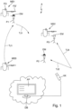
- FIG.1 an embodiment of the method according to the invention.
- Fig.1 shows an embodiment of the method according to the invention.
- This figure shows parts of an automation system A.
- a field device FG for example a fill level measuring device using radar, is attached to the tank.
- a field device FG' is attached, for example a flow measuring device based on the Coriolis principle.
- the measuring points MS1, MS2, MS3, as well as the space between the measuring points MS1, MS2, MS3, are recorded by at least one video camera VK.
- the recorded photos/videos are transferred to a database DB. This is available on a cloud platform and can be contacted by an operator via the Internet.
- the database DB is connected to an application AP, which evaluates the recordings.
- the purpose of the recording is to collect the location data of persons P1, P2, P3 from objects that are located in facility A and to evaluate the location data for any abnormalities.
- the AP application groups these three people P1, P2, P3 based on identification features EM. Specifically, this is the helmet of the people P1, P2, P3.
- the color of the helmet defines the role of the people P1, P2, P3 in facility A. Black stands for the role "service technician”; white stands for the role "supplier".
- the trajectories T1, T2, T3 of the persons P1, P2, P3 are recorded, as well as the times and duration of the stay of the persons P1, P2, P3 at the measuring points MS1, MS2, MS3.
- the service technician P1 is on a routine round to the individual measuring points MS1, MS2, MS3, whereby the Service technician P2 is on the way to the measuring point MS2 where a problem has occurred and the supplier P3 is on the way to the measuring point MS2 to fill the tank.
- the stay data determined in this way is also stored in the DB database.
- the stay data in the DB database is evaluated using the AP application.
- the stay data is filtered.
- the filtering refers, for example, to a defined period of time and/or to a defined role of persons P1, P2, P3 and/or to one or more measuring points MS1, MS2, MS3.
- the filtered stay data is then examined for anomalies.
- anomalies include, for example, a frequent appearance of a certain group of people at a measuring point MS1, MS2, MS3. It can also be checked whether certain groups of people visit the measuring points MS1, MS2, MS3 at regular intervals.
- abnormalities in system A can be identified which cannot be determined using diagnostic values from field devices FG, FG', or to clarify diagnostic cases.
- measured values from a flow meter which are outside a defined standard interval could be explained by a pipe being blocked, for example.
- the cause can be determined from the location data.
- service technician P1 is at the respective measuring point MS1, MS2, MS3 at regular intervals, particularly as part of the maintenance routine - for example to knock on the pipe with an object, which removes buildup inside the pipe.
- the location data makes it clear that service technician P1 was no longer at the respective measuring point MS1, MS2, MS3 for a longer period of time before the error occurred, which meant that the buildup inside the pipe was no longer removed.
- the stay data can be linked to other data sets, such as weather data, forecast data, financial data and/or Position data of the field devices. In this way, additional insights can be gained.
Landscapes
- Engineering & Computer Science (AREA)
- General Physics & Mathematics (AREA)
- Physics & Mathematics (AREA)
- Business, Economics & Management (AREA)
- General Engineering & Computer Science (AREA)
- Quality & Reliability (AREA)
- Manufacturing & Machinery (AREA)
- Human Resources & Organizations (AREA)
- Automation & Control Theory (AREA)
- Theoretical Computer Science (AREA)
- Strategic Management (AREA)
- Economics (AREA)
- Databases & Information Systems (AREA)
- Marketing (AREA)
- Tourism & Hospitality (AREA)
- Educational Administration (AREA)
- General Business, Economics & Management (AREA)
- Entrepreneurship & Innovation (AREA)
- Software Systems (AREA)
- Data Mining & Analysis (AREA)
- Game Theory and Decision Science (AREA)
- Operations Research (AREA)
- Development Economics (AREA)
- Primary Health Care (AREA)
- General Health & Medical Sciences (AREA)
- Health & Medical Sciences (AREA)
- Testing And Monitoring For Control Systems (AREA)
- Testing Or Calibration Of Command Recording Devices (AREA)
Description
Die Erfindung betrifft ein Verfahren zum Überwachen einer Anlage der Prozessautomatisierung, wobei in der Anlage eine Vielzahl von Messstellen vorgesehen ist.The invention relates to a method for monitoring a process automation system, wherein a plurality of measuring points are provided in the system.
Aus dem Stand der Technik sind bereits Feldgeräte bekannt geworden, die in industriellen Anlagen zum Einsatz kommen. In der Automatisierungstechnik ebenso wie in der Fertigungsautomatisierung werden vielfach Feldgeräte eingesetzt. Als Feldgeräte werden im Prinzip alle Geräte bezeichnet, die prozessnah eingesetzt werden und die prozessrelevante Informationen liefern oder verarbeiten. So werden Feldgeräte zur Erfassung und/oder Beeinflussung von Prozessgrößen verwendet. Zur Erfassung von Prozessgrößen dienen Sensorsysteme. Diese werden beispielsweise zur Druck- und Temperaturmessung, Leitfähigkeitsmessung, Durchflussmessung, pH-Messung, Füllstandmessung, etc. verwendet und erfassen die entsprechenden Prozessvariablen Druck, Temperatur, Leitfähigkeit, pH-Wert, Füllstand, Durchfluss etc. Zur Beeinflussung von Prozessgrößen werden Aktorsysteme verwendet. Diese sind beispielsweise Pumpen oder Ventile, die den Durchfluss einer Flüssigkeit in einem Rohr oder den Füllstand in einem Behälter beeinflussen können. Neben den zuvor genannten Messgeräten und Aktoren werden unter Feldgeräten auch Remote I/Os, Funkadapter bzw. allgemein Geräte verstanden, die auf der Feldebene angeordnet sind.Field devices that are used in industrial plants are already known from the state of the art. Field devices are often used in automation technology as well as in production automation. Field devices are basically all devices that are used close to the process and that provide or process process-relevant information. Field devices are used to record and/or influence process variables. Sensor systems are used to record process variables. These are used, for example, for pressure and temperature measurement, conductivity measurement, flow measurement, pH measurement, level measurement, etc. and record the corresponding process variables pressure, temperature, conductivity, pH value, level, flow, etc. Actuator systems are used to influence process variables. These are, for example, pumps or valves that can influence the flow of a liquid in a pipe or the level in a container. In addition to the measuring devices and actuators mentioned above, field devices also include remote I/Os, radio adapters or general devices that are arranged at the field level.
Eine Vielzahl solcher Feldgeräte wird von der Endress+Hauser-Gruppe produziert und vertrieben.A large number of such field devices are produced and distributed by the Endress+Hauser Group.
In modernen Industrieanlagen sind Feldgeräte in der Regel über Kommunikationsnetzwerke wie beispielsweise Feldbusse (Profibus®, Foundation® Fieldbus, HART®, etc.) mit übergeordneten Einheiten verbunden. Bei den übergeordneten Einheiten handelt es sich um Steuereinheiten, wie beispielsweise eine SPS (speicherprogrammierbare Steuerung) oder einen PLC (Programmable Logic Controller). Die übergeordneten Einheiten dienen unter anderem zur Prozesssteuerung, sowie zur Inbetriebnahme der Feldgeräte. Die von den Feldgeräten, insbesondere von Sensoren, erfassten Messwerte werden über das jeweilige Bussystem an eine (oder gegebenenfalls mehrere) übergeordnete Einheit(en) übermittelt, die die Messwerte gegebenenfalls weiterverarbeiten und an den Leitstand der Anlage weiterleiten. Der Leitstand dient zur Prozessvisualisierung, Prozessüberwachung und Prozessteuerung über die übergeordneten Einheiten. Daneben ist auch eine Datenübertragung von der übergeordneten Einheit über das Bussystem an die Feldgeräte erforderlich, insbesondere zur Konfiguration und Parametrierung von Feldgeräten sowie zur Ansteuerung von Aktoren.In modern industrial plants, field devices are usually connected to higher-level units via communication networks such as field buses (Profibus ® , Foundation ® Fieldbus, HART ® , etc.). The higher-level units are control units such as a PLC (programmable logic controller). The higher-level units are used, among other things, for process control and for commissioning the field devices. The measured values recorded by the field devices, in particular by sensors, are transmitted via the respective bus system to one (or The measured values are transmitted to (if necessary, several) higher-level units, which may further process the measured values and forward them to the system's control center. The control center is used for process visualization, process monitoring and process control via the higher-level units. In addition, data transmission from the higher-level unit to the field devices via the bus system is also required, in particular for the configuration and parameterization of field devices and for controlling actuators.
Im Zuge der Industrie 4.0, bzw. IIoT ("Industrial Internet of Things") werden die von den Feldgeräten erzeugten Daten auch häufig direkt aus dem Feld mithilfe sogenannter Datenumsetzungseinheiten, welche beispielsweise als "Edge Devices" oder "Cloud Gateways" bezeichnet werden, erhoben und automatisiert an eine zentrale cloudfähige Datenbank übermittelt, auf welcher sich eine Applikation befindet. Auf diese Applikation, welche unter anderem Funktionen zur Visualisierung und weiteren Bearbeitung der auf der Datenbank gespeicherten Daten bietet, kann von einem Benutzer mittels Internet zugegriffen werden.In the course of Industry 4.0, or IIoT ("Industrial Internet of Things"), the data generated by the field devices is often collected directly from the field using so-called data conversion units, which are referred to as "edge devices" or "cloud gateways", for example, and automatically transmitted to a central cloud-enabled database on which an application is located. This application, which offers functions for visualizing and further processing the data stored in the database, can be accessed by a user via the Internet.
Mittels dieser Methoden ist die Überwachung der elektronischen Komponenten der Anlage - also der Feldgeräte und Steuerungseinheiten- möglich. Bei diesen Methoden bleiben allerdings die Betrachtung, bzw. der Einfluss rein mechanischer Komponenten, beispielsweise Rohrverbindungen, außen vor. Die Veränderung solcher mechanischer Komponenten, beispielsweise bei Ansatzbildung oder Leckage, könnten nur indirekt detektiert werden, beispielsweise über veränderte Messcharakteristiken der Feldgeräte. Im Fehlerfall wird daher mitunter eine große Zeitspanne benötigt, um die genaue Fehlerursache zu ermitteln.These methods make it possible to monitor the electronic components of the system - i.e. the field devices and control units. However, these methods do not take into account the influence of purely mechanical components, such as pipe connections. Changes to such mechanical components, such as buildup or leaks, can only be detected indirectly, for example via changes in the measurement characteristics of the field devices. In the event of a fault, a long period of time is therefore sometimes required to determine the exact cause of the fault.
Die
Die Veröffentlichung
Die
Ausgehend von dieser Problematik liegt der Erfindung die Aufgabe zugrunde, ein Verfahren vorzustellen, welche es erlaubt, die Ursache eines Fehlers in einer Anlage der Prozessautomatisierung schnell und zuverlässig zu ermitteln.Based on this problem, the invention is based on the object of presenting a method which allows the cause of an error in a process automation system to be determined quickly and reliably.
Die Aufgabe wird durch ein Verfahren gemäß Patentanspruch 1 gelöst.The object is achieved by a method according to patent claim 1.
Der große Vorteil des erfindungsgemäßen Verfahrens besteht darin, dass für die Findung der Fehlerursache an Messstellen in der Anlage auch Informationen eingeholt werden, welche von Feldgeräten und Steuereinheiten nicht messbar sind. Konkret werden Aufenthaltsorte und Aufenthaltszeiten von Personen in der Anlage erfasst und ausgewertet. So könnten beispielsweise Messwerte eines Durchflussmessgerätes, welche sich außerhalb eines definierten Normintervalls dadurch erklärt werden, dass beispielsweise eine Rohrleitung verstopft ist. Aus den Aufenthaltsdaten kann die Ursache ermittelt werden. Beispielsweise könnte ersichtlich sein, dass sich ein Wartungsmechaniker in regelmäßigen Zeitabständen bei der Messstelle befindet - beispielsweise um mit einem Gegenstand an das Rohr zu klopfen, was Ansatz im Rohrinneren entfernt. Durch die Aufenthaltsdaten wird deutlich, dass sich der Wartungsmechaniker in einem längeren Zeitraum vor dem Auftreten des Fehlers nicht mehr an der Messstelle aufgehalten hat, wodurch der Ansatz im Rohrinneren nicht mehr gelöst wurde.The great advantage of the method according to the invention is that in order to find the cause of the error at measuring points in the system, information that cannot be measured by field devices and control units is also obtained. Specifically, the locations and times of people in the system are recorded and evaluated. For example, measured values from a flow meter that are outside a defined standard interval could be explained by a pipe being blocked, for example. The cause can be determined from the location data. For example, it could be evident that a maintenance mechanic is at the measuring point at regular intervals - for example to knock on the pipe with an object, which removes buildup inside the pipe. The location data makes it clear that the maintenance mechanic had not been at the measuring point for a long time before the error occurred, which meant that the buildup inside the pipe was no longer removed.
Das Verfahren ist außerdem auch in älteren, rein analogen Anlagen einsetzbar, in denen überhaupt keine digitale Daten- und Diagnoseauswertung verfügbar ist.The method can also be used in older, purely analogue systems in which no digital data and diagnostic evaluation is available at all.
Die Aufenthaltsdaten werden beispielsweise von einem in der Leitwarte integrierten übergeordneten System berechnet und ausgewertet.The stay data is calculated and evaluated, for example, by a higher-level system integrated in the control room.
Eine Messstelle besteht aus einer oder mehreren Anlagenkomponenten, beispielsweise einem Tank oder einer Rohrleitung, sowie aus zumindest einem Feldgerät. Feldgeräte im Sinne der vorliegenden Erfindung wurden bereits im einleitenden Teil der Beschreibung beispielhaft genannt.A measuring point consists of one or more system components, for example a tank or a pipeline, as well as at least one field device. Field devices in the sense of the present invention have already been mentioned as examples in the introductory part of the description.
Gemäß einer vorteilhaften Ausgestaltung des erfindungsgemäßen Verfahrens ist vorgesehen, dass die Aufenthaltsdaten in einer Datenbank gespeichert werden. Hierbei handelt es sich insbesondere um eine Datenbank, welche in einer Cloud-Umgebung implementiert ist. Alternativ befindet sich die Datenbank lokal in der Anlage, beispielsweise in der Leitwarte, oder in der Umgebung der Anlage.According to an advantageous embodiment of the method according to the invention, the location data is stored in a database. This is in particular a database that is implemented in a cloud environment. Alternatively, the database is located locally in the system, for example in the control room, or in the environment of the system.
Gemäß einer bevorzugten Ausgestaltung des erfindungsgemäßen Verfahrens ist vorgesehen, dass die Aufenthaltsdaten im Zuge des Auswertens in einem Diagramms, insbesondere einer Heatmap, visualisiert werden, in welchem die Anzahl der Zeitpunkte des Auftretens und/oder die Aufenthaltsdauer der Personen an einer jeweiligen Messstelle kumuliert dargestellt wird. Auf diese Art und Weise sind Häufungen für einen Bediener schnell ersichtlich. Beispielsweise können hierdurch wartungsintensive Messstellen schnell identifiziert werden.According to a preferred embodiment of the method according to the invention, the location data is visualized in the course of the evaluation in a diagram, in particular a heat map, in which the number of times of occurrence and/or the duration of stay of the people at a respective measuring point is shown cumulatively. In this way, clusters are quickly apparent to an operator. For example, maintenance-intensive measuring points can be quickly identified in this way.
Erfindungsgemäß werden die Personen anhand von Erkennungsmerkmalen eingruppiert.According to the invention, people are grouped based on identifying features.
Erfindungsgemäß werden die Personen anhand der Befugnis und/oder der Rolle eingruppiert, wobei die Befugnis und/oder die Rolle in einem Erkennungsmerkmal definiert ist, welches an der Person angebracht ist, insbesondere als Kleidungsstück in einer zur jeweiligen Befugnis und/oder Rolle zuordenbaren Farbe. Rollen einer Person sind beispielsweise deren auszuführende Funktion, beispielsweise Service-/Wartungstechniker, Prozessingenieur, Lieferant, Besucher, etc. Bestimmte Bereiche einer Anlage können für unbefugte Personen gesperrt sein. Explosionsgeschütze Bereiche dürfen beispielsweise nur von Fachkräften betreten werden, welche über das dementsprechende Knowhow und die erforderliche Schutzausrüstung verfügen.According to the invention, people are grouped according to their authority and/or role, whereby the authority and/or role is defined in an identifying feature that is attached to the person, in particular as a piece of clothing in a color that can be assigned to the respective authority and/or role. Roles of a person are, for example, the function they perform, for example service/maintenance technician, process engineer, supplier, visitor, etc. Certain areas of a plant can be closed to unauthorized persons. Explosion-proof areas, for example, may only be entered by specialists who have the corresponding know-how and the necessary protective equipment.
Bei dem Kleidungsstück handelt es sich beispielsweise um einen Helm oder ein sonstiges leicht erkennbares Kleidungsstück.The item of clothing could be, for example, a helmet or other easily recognizable item of clothing.
Damit ist es des Weiteren auch möglich, eine Alarmfunktion in der Anlage zu implementieren. Im Falle dass Personen in für sie unbefugte Bereiche registriert werden, wird ein Alarm ausgelöst.This also makes it possible to implement an alarm function in the system. If people are registered in areas that are not authorized for them, an alarm is triggered.
Erfindungsgemäß wird das Auswerten der Aufenthaltsdaten automatisch, insbesondere mittels einer mit der Datenbank verknüpften Applikation, vorgenommen, wobei das Ergebnis des Auswertens an einen Bediener ausgegeben wird. Der Bediener wählt im Voraus Kriterien aus, welche bei der Auswertung berücksichtigt werden.According to the invention, the evaluation of the stay data is carried out automatically, in particular by means of an application linked to the database, with the result of the evaluation being output to an operator. The operator selects criteria in advance which are to be taken into account in the evaluation.
Erfindungsgemäß werden die Aufenthaltsdaten, insbesondere automatisch, hinsichtlich zumindest einer der folgenden Auffälligkeiten ausgewertet werden:
- Gehäufte Aufenthaltsdauer von Personen und/oder an zumindest einer bestimmten Messstelle; und/oder
- Gehäufte Anzahl an Zeitpunkten von Personen an zumindest einer bestimmten Messstelle.
- Accumulated length of stay of persons and/or at at least one specific measuring point; and/or
- Accumulated number of times of persons at at least one specific measuring point.
Eine vorteilhafte Weiterbildung des erfindungsgemäßen Verfahrens sieht vor, dass eine Vorhersage bezüglich einer zu erwartenden kumulierten Aufenthaltsdauer an zumindest einer Messstelle berechnet wird.An advantageous development of the method according to the invention provides that a prediction is calculated with regard to an expected cumulative length of stay at at least one measuring point.
Alternativ können auch weitere Vorhersagen oder Trends berechnet werden.Alternatively, further predictions or trends can be calculated.
Beispielsweise wird dafür eine Mustererkennung oder eine Wahrscheinlichkeitsrechnung angewandt. Über Machine Learning können auch bestimmte Muster erkannt werden und auf dieser Basis Zukunftsprognosen erstellt werden.For example, pattern recognition or probability calculations are used for this purpose. Machine learning can also be used to recognize certain patterns and, on this basis, to make future predictions.
Gemäß einer bevorzugten Ausgestaltung des erfindungsgemäßen Verfahrens ist vorgesehen, dass die Aufenthaltsdaten vor dem Auswerten oder nach dem Auswerten hinsichtlich zumindest einem der folgenden Merkmale gefiltert werden:
- Filtern hinsichtlich zumindest eines Erkennungsmerkmals;
- Filtern hinsichtlich zumindest eines definierten Zeitraums; und/oder
- Filtern hinsichtlich zumindest einer Messstelle.
- Filtering with respect to at least one identifying feature;
- Filtering with respect to at least one defined period of time; and/or
- Filter with respect to at least one measuring point.
Es kann hierbei auch vorgesehen sein, diverse Zeiträume auszublenden. Als Beispiel sei hier ein "Tag der offenen Türe genannt", an welchem eine Begehung der Anlage von ansonsten unbefugten Personen stattfinden kann. Dieser Zeitraum hat keinen Einfluss auf die Auswertungen und wird daher nicht betrachtet.It can also be planned to hide various time periods. An example of this would be an "open day" during which otherwise unauthorized persons can visit the facility. This time period has no influence on the evaluations and is therefore not taken into account.
Gemäß einer vorteilhaften Ausgestaltung des erfindungsgemäßen Verfahrens ist vorgesehen, dass die Aufenthaltsdaten vor dem Auswerten mit zumindest einem Datensatz der folgenden Daten verknüpft werden:
- Wetterdaten;
- Produktionsdaten; und/oder
- Finanzdaten.
- weather data;
- production data; and/or
- Financial data.
Durch Verknüpfung der Aufenthaltsdaten mit dem weiteren Datensatz kann ein Mehrwert geschaffen werden:
- Mittels der Wetterdaten kann der Einfluss von Umgebungswerten berücksichtigt werden. Beispielsweise kann geprüft werden, ob bei hohen Temperaturen bestimmte Bereiche/Messstellen der Anlage wartungsintensiver sind als andere.
- Mittels der Produktionsdaten kann beispielsweise eine Häufung des Wartungsbedarfs einer Komponente der Anlage ermittelt werden, welches Produktionsdatum vor/nach einem bestimmten Datum liegt.
- Mittels der Finanzdaten können kostenintensive/kostengünstige Bereiche/Messstellen der Anlage identifiziert werden. Beispielsweise muss eine wartungsintensive Messstelle nicht unbedingt teuer sein - es interessiert eher die kostenintensivste Messstelle der Anlage, beispielsweise aufgrund hohen Materialverschleißes. Hieraus könnte abgeleitet werden, in welchem Bereich es Sinn ergibt, über kostensenkende Optimierungen nachzudenken.
- The influence of environmental values can be taken into account using weather data. For example, it can be checked whether certain areas/measuring points of the system require more maintenance than others at high temperatures.
- Using the production data, it is possible to determine, for example, the frequency of maintenance requirements for a component of the system and which production date lies before/after a certain date.
- Using the financial data, cost-intensive/low-cost areas/measuring points of the plant can be identified. For example, a maintenance-intensive measuring point does not necessarily have to be expensive - it is more important to look at the most cost-intensive measuring point of the plant, for example due to high Material wear and tear. From this, it could be deduced in which areas it makes sense to think about cost-reducing optimizations.
Gemäß einer bevorzugten Ausgestaltung des erfindungsgemäßen Verfahrens ist vorgesehen, dass die Aufenthaltsdaten hinsichtlich zumindest einer der folgenden Auffälligkeiten ausgewertet werden:
- Zumindest einem Temperaturbereich, bzw. einer bestimmten Temperatur;
- Zumindest einem Herstellungsdatum, bzw. einem Herstellungszeitraum von Komponenten der Messstellen; und/oder
- Hinsichtlich der Wartungskosten der Messstellen.
- At least a temperature range or a specific temperature;
- At least a manufacturing date or a manufacturing period of components of the measuring points; and/or
- Regarding the maintenance costs of the measuring points.
Erfindungsgemäß werden die Bewegungen der folgenden Methode erfasst:
- Auswertung von Videobildern, welche mittels zumindest einer in der Anlage angeordneten Videokamera aufgezeichnet werden.
- Evaluation of video images recorded by at least one video camera arranged in the system.
Auch weitere Arten der Bewegungserfassung sind möglich, beispielsweise über Kontaktpunkte im Boden, etc. Es ist auch möglich, verschiedene Erfassungsmethoden miteinander zu kombinieren. Es versteht sich von selbst, dass eine Auswertung nach Erkennungsmerkmalen, insbesondere nach den Farben von Kleidungsstücken der Personen, nur bei einer optischen Erfassungsmethode möglich ist.Other types of motion detection are also possible, for example via contact points in the floor, etc. It is also possible to combine different detection methods. It goes without saying that an evaluation based on identifying features, in particular the colors of people's clothing, is only possible with an optical detection method.
Eine bevorzugte Weiterbildung des erfindungsgemäßen Verfahrens sieht vor, dass die Aufenthaltsdaten zusätzlich Trajektorien der einzelnen Personen umfassen. Dadurch können die Lauf-/Bewegungswege der Personen eingesehen werden.A preferred development of the method according to the invention provides that the location data additionally include trajectories of the individual persons. This makes it possible to view the walking/movement paths of the persons.
Die Erfindung wird anhand der nachfolgenden Figuren näher erläutert. Es zeigen
Die Messstellen MS1, MS2, MS3, sowie der zwischen den Messstellen MS1, MS2, MS3 gelegene Raum, werden durch zumindest eine Videokamera VK aufgezeichnet. Die aufgezeichneten Fotos/Videos werden an eine Datenbank DB übertragen. Diese ist insbesondere auf einer Cloud-Plattform vorhanden und durch einen Bediener mittels Internet kontaktierbar. Die Datenbank DB ist mit einer Applikation AP verbunden, welche die Aufzeichnungen auswertet.The measuring points MS1, MS2, MS3, as well as the space between the measuring points MS1, MS2, MS3, are recorded by at least one video camera VK. The recorded photos/videos are transferred to a database DB. This is available on a cloud platform and can be contacted by an operator via the Internet. The database DB is connected to an application AP, which evaluates the recordings.
Zweck der Aufzeichnung ist es, Aufenthaltsdaten von Personen P1, P2, P3 von Objekten zu erheben, welche sich in der Anlage A aufhalten und die Aufenthaltsdaten auf Auffälligkeiten auszuwerten. In dem in
Erfasst werden hierbei die Trajektorien T1, T2, T3 der Personen P1, P2, P3, sowie die Zeitpunkte des Aufhaltens und die Zeitdauer des Aufhaltens der Personen P1, P2, P3 an den Messstellen MS1, MS2, MS3. Der Servicetechniker P1 befindet sich auf einem Routinerundgang zu den einzelnen Messstellen MS1, MS2, MS3, wobei sich der Servicetechniker P2 auf dem Weg zu der Messstelle MS2 befindet, an welcher ein Problem aufgetreten ist, und wobei sich der Lieferant P3 auf dem Weg zu der Messstelle MS2 befindet, um den Tank zu füllen.The trajectories T1, T2, T3 of the persons P1, P2, P3 are recorded, as well as the times and duration of the stay of the persons P1, P2, P3 at the measuring points MS1, MS2, MS3. The service technician P1 is on a routine round to the individual measuring points MS1, MS2, MS3, whereby the Service technician P2 is on the way to the measuring point MS2 where a problem has occurred and the supplier P3 is on the way to the measuring point MS2 to fill the tank.
Diese auf diese Art und Weise ermittelten Aufenthaltsdaten werden ebenfalls in der Datenbank DB abgelegt. Mittels der Applikation AP werden die auf der Datenbank DB befindlichen Aufenthaltsdaten ausgewertet.The stay data determined in this way is also stored in the DB database. The stay data in the DB database is evaluated using the AP application.
In einem ersten Schritt werden die Aufenthaltsdaten gefiltert. Die Filterung bezieht sich beispielsweise auf einen definierten Zeitraum und/oder auf eine definierte Rolle von Personen P1, P2, P3 und/oder auf eine oder mehrere Messstellen MS1, MS2, MS3.In a first step, the stay data is filtered. The filtering refers, for example, to a defined period of time and/or to a defined role of persons P1, P2, P3 and/or to one or more measuring points MS1, MS2, MS3.
Anschließend werden die gefilterten Aufenthaltsdaten auf Auffälligkeiten untersucht. Solche Auffälligkeiten sind beispielsweise ein gehäuftes Auftreten einer bestimmten Personengruppe an einer Messstelle MS1, MS2, MS3. Auch kann überprüft werden, ob bestimmte Personengruppen in regelmäßigen Abständen die Messstellen MS1, MS2, MS3 aufsuchen.The filtered stay data is then examined for anomalies. Such anomalies include, for example, a frequent appearance of a certain group of people at a measuring point MS1, MS2, MS3. It can also be checked whether certain groups of people visit the measuring points MS1, MS2, MS3 at regular intervals.
Auf diese Weise können Auffälligkeiten in der Anlage A ermittelt werden, welche mittels Diagnosewerten der Feldgeräte FG, FG' nicht ermittelbar sind, bzw. um Diagnosefälle aufzuklären. So könnten beispielsweise Messwerte eines Durchflussmessgerätes, welche sich außerhalb eines definierten Normintervalls dadurch erklärt werden, dass beispielsweise eine Rohrleitung verstopft ist. Aus den Aufenthaltsdaten kann die Ursache ermittelt werden. Beispielsweise könnte ersichtlich sein, dass sich der Servicetechniker P1 in regelmäßigen Zeitabständen, insbesondere im Rahmen der Wartungsroutine, bei der jeweiligen Messstelle MS1, MS2, MS3 befindet - beispielsweise um mit einem Gegenstand an das Rohr zu klopfen, was Ansatz im Rohrinneren entfernt. Durch die Aufenthaltsdaten wird deutlich, dass sich der Servicetechniker P1 in einem längeren Zeitraum vor dem Auftreten des Fehlers nicht mehr an der jeweiligen Messstelle MS1, MS2, MS3 aufgehalten hat, wodurch der Ansatz im Rohrinneren nicht mehr gelöst wurde.In this way, abnormalities in system A can be identified which cannot be determined using diagnostic values from field devices FG, FG', or to clarify diagnostic cases. For example, measured values from a flow meter which are outside a defined standard interval could be explained by a pipe being blocked, for example. The cause can be determined from the location data. For example, it could be evident that service technician P1 is at the respective measuring point MS1, MS2, MS3 at regular intervals, particularly as part of the maintenance routine - for example to knock on the pipe with an object, which removes buildup inside the pipe. The location data makes it clear that service technician P1 was no longer at the respective measuring point MS1, MS2, MS3 for a longer period of time before the error occurred, which meant that the buildup inside the pipe was no longer removed.
Vorteilhafterweise können die Aufenthaltsdaten mit weiteren Datensätzen verknüpft werden, beispielsweise Wetterdaten, Prognosedaten, Finanzdaten und/oder mit Positionsdaten der Feldgeräte. Auf diese Art und Weise können zusätzliche Erkenntnisse gewonnen werden.Advantageously, the stay data can be linked to other data sets, such as weather data, forecast data, financial data and/or Position data of the field devices. In this way, additional insights can be gained.
- AA
- AnlageAttachment
- APAP
- Applikationapplication
- DBDB
- DatenbankDatabase
- EMEM
- ErkennungsmerkmaleIdentification features
- FG, FG'FG, FG'
- FeldgeräteField devices
- MS1, MS2, MS3MS1, MS2, MS3
- MessstellenMeasuring points
- P1, P2, P3P1, P2, P3
- Personenpersons
- TJ1, TJ2, TJ3TJ1, TJ2, TJ3
- TrajektorienTrajectories
- VKUK
- VideokameraVideo camera
Claims (8)
- Method for monitoring an installation (A) of process automation, wherein a plurality of measuring points (MS1, MS2, MS3) is provided in the installation (A), wherein a measuring point consists of one or more components, comprising:- Detection of movements of persons (P1, P2, P3) located in the system (A) by means of an evaluation of video images, which are recorded by means of at least one video camera (VK) arranged in the system (A);- Calculation of stay data, including times of stay and/or the respective duration of stay, of the respective persons (P1, P2, P3) at the individual measuring points (MS1, MS2, MS3) on the basis of the recorded movements;- Grouping of the persons (P1, P2, P3) on the basis of identification features (EM), the persons (P1, P2, P3) being grouped on the basis of the authority and/or the role, the authority and/or the role being defined in an identification feature (EM) which is attached to the respective person (P1, P2, P3), an assignable color of an item of clothing being provided as an identification feature for the respective authority and/or role;- Linking the stay data with at least one data record from weather data, production data;- Evaluation of the stay data with regard to at least one of the following anomalies:a) Accumulated duration of stay of persons (P1, P2, P3) of a specific group of persons at at least one specific measuring point (MS1, MS2, MS3); and/orb) Accumulated number of times of persons (P1, P2, P3) of a certain group of persons at at least one certain measuring point (MS1, MS2, MS3), as well as determination of a certain measuring point of the system as being more maintenance-intensive and/or accumulation of the maintenance requirement of a component of the system and use of the link; and- Output of the result to an operator.
- The method according to claim 1, wherein the stay data is stored in a database (DB).
- Method according to at least one of the previous claims, wherein the stay data are visualized in the course of the evaluation in a diagram, in particular a heat map, in which the number of times the persons (P1, P2, P3) have been present and/or the duration of their stay at a respective measuring point (MS1, MS2, MS3) is displayed cumulatively.
- Method according to at least one of the previous claims, wherein a prediction is calculated with respect to an expected cumulative duration of stay at at least one measuring point (MS1, MS2, MS3).
- The method according to at least one of the preceding claims, wherein the stay data is filtered before the evaluation or after the evaluation with respect to at least one of the following features:- Filtering with regard to at least one identification feature (EM);- Filtering with regard to at least one defined time period; and/or- Filtering with regard to at least one measuring point (MS1, MS2, MS3).
- The method according to claim 1, wherein the stay data is evaluated with respect to at least one of the following abnormalities:- At least a temperature range or a certain temperature;- At least one production date or production period of components (FG, FG') of the measuring points (MS1, MS2, MS3); and/or- With regard to the maintenance costs of the measuring points (MS1, MS2, MS3).
- The method according to at least one of the preceding claims, wherein the movements are detected by at least one of the following methods:- acquisition of GPS data, wherein the persons (P1, P2, P3) are each equipped with at least one GPS module; and/or- Detection of movements by means of at least one infrared movement detector arranged in the system (A).
- Method according to at least one of the previous claims, wherein the stay data additionally comprise trajectories (TJ1, TJ2, TJ3) of the individual persons (P1, P2, P3).
Applications Claiming Priority (2)
| Application Number | Priority Date | Filing Date | Title |
|---|---|---|---|
| DE102017123221.4A DE102017123221A1 (en) | 2017-10-06 | 2017-10-06 | Method for monitoring a plant of automation technology |
| PCT/EP2018/074472 WO2019068434A1 (en) | 2017-10-06 | 2018-09-11 | METHOD FOR MONITORING AN AUTOMATION ENGINEERING SYSTEM |
Publications (2)
| Publication Number | Publication Date |
|---|---|
| EP3692425A1 EP3692425A1 (en) | 2020-08-12 |
| EP3692425B1 true EP3692425B1 (en) | 2024-07-24 |
Family
ID=63579341
Family Applications (1)
| Application Number | Title | Priority Date | Filing Date |
|---|---|---|---|
| EP18769334.6A Active EP3692425B1 (en) | 2017-10-06 | 2018-09-11 | Method for monitoring an automation system |
Country Status (4)
| Country | Link |
|---|---|
| US (1) | US20200278661A1 (en) |
| EP (1) | EP3692425B1 (en) |
| DE (1) | DE102017123221A1 (en) |
| WO (1) | WO2019068434A1 (en) |
Citations (2)
| Publication number | Priority date | Publication date | Assignee | Title |
|---|---|---|---|---|
| DE102014106211A1 (en) * | 2014-04-10 | 2015-10-15 | GM Global Technology Operations LLC (n. d. Ges. d. Staates Delaware) | Vision-based multi-camera factory monitoring with dynamic integrity assessment |
| WO2016030517A1 (en) * | 2014-08-29 | 2016-03-03 | Haunsperger Johann | Service and information system for buildings and methods for the automatic handling of malfunctions or of service and maintenance work and for the documentation thereof |
Family Cites Families (3)
| Publication number | Priority date | Publication date | Assignee | Title |
|---|---|---|---|---|
| EP1673750B1 (en) * | 2003-10-07 | 2013-11-06 | Z-Safety Systems NV | Safety monitoring system |
| US9230250B1 (en) * | 2012-08-31 | 2016-01-05 | Amazon Technologies, Inc. | Selective high-resolution video monitoring in a materials handling facility |
| KR20170016438A (en) * | 2014-06-03 | 2017-02-13 | 엘리먼트, 인크. | Attendance authentication and management in connection with mobile devices |
-
2017
- 2017-10-06 DE DE102017123221.4A patent/DE102017123221A1/en not_active Withdrawn
-
2018
- 2018-09-11 EP EP18769334.6A patent/EP3692425B1/en active Active
- 2018-09-11 US US16/753,860 patent/US20200278661A1/en not_active Abandoned
- 2018-09-11 WO PCT/EP2018/074472 patent/WO2019068434A1/en not_active Ceased
Patent Citations (2)
| Publication number | Priority date | Publication date | Assignee | Title |
|---|---|---|---|---|
| DE102014106211A1 (en) * | 2014-04-10 | 2015-10-15 | GM Global Technology Operations LLC (n. d. Ges. d. Staates Delaware) | Vision-based multi-camera factory monitoring with dynamic integrity assessment |
| WO2016030517A1 (en) * | 2014-08-29 | 2016-03-03 | Haunsperger Johann | Service and information system for buildings and methods for the automatic handling of malfunctions or of service and maintenance work and for the documentation thereof |
Non-Patent Citations (1)
| Title |
|---|
| WANT R ET AL: "ACTIVE BADGES AND PERSONAL INTERACTIVE COMPUTING OBJECTS", IEEE TRANSACTIONS ON CONSUMER ELECTRONICS, IEEE SERVICE CENTER, NEW YORK, NY, US, vol. 38, no. 1, 1 February 1992 (1992-02-01), pages 10 - 20, XP000297357, ISSN: 0098-3063, DOI: 10.1109/30.125076 * |
Also Published As
| Publication number | Publication date |
|---|---|
| DE102017123221A1 (en) | 2019-04-11 |
| US20200278661A1 (en) | 2020-09-03 |
| EP3692425A1 (en) | 2020-08-12 |
| WO2019068434A1 (en) | 2019-04-11 |
Similar Documents
| Publication | Publication Date | Title |
|---|---|---|
| EP3077878B1 (en) | Computer-implemented method and system for automatic monitoring and status detection of entire process stages in a process unit | |
| EP3279756B1 (en) | Diagnostic device and method for monitoring the operation of a technical plant | |
| DE102012108990A1 (en) | Method for locating a field device in an automation system | |
| DE102007039531A1 (en) | Method for obtaining maintenance-relevant information about a plant | |
| EP3665536B1 (en) | Determination of the causes of anomaly events | |
| EP3538962B1 (en) | Method for analysing malfunctions in a system of process automation | |
| WO2022128321A1 (en) | Method for reporting a fault in an automation system | |
| WO2019105634A1 (en) | Method for monitoring an automation system | |
| DE102012101461A1 (en) | Method for controlling operation of processing unit in automation control engineering field, involves performing loop test by personnel whose positive result represents permission for field device to process-start-up in processing unit | |
| WO2023117317A1 (en) | Method for the automated inspection of a field device | |
| EP3821306A1 (en) | Method for parametrising a sensor system | |
| WO2019068435A1 (en) | SMARTWATCH AND METHOD OF MAINTAINING AN AUTOMATION TECHNOLOGY PLANT | |
| WO2024132444A1 (en) | Method for creating or updating a digital twin for an automation field device | |
| DE102016122051A1 (en) | Method and system for determining diagnostic information of at least one field device of process automation | |
| EP3555714B1 (en) | Method for the application-specific setting of a field device | |
| DE102018123436A1 (en) | Process for monitoring a plant in automation technology | |
| WO2019068434A1 (en) | METHOD FOR MONITORING AN AUTOMATION ENGINEERING SYSTEM | |
| DE102011084321A1 (en) | Communication unit for use in system of process automation technology, has user interface which represents information based on system structure, while system structure on field bus topology is inversely mapped with drawing algorithm | |
| DE102017131087A1 (en) | Method for monitoring a measuring point in a process automation system | |
| DE102019134021A1 (en) | Method for monitoring an automation technology system | |
| DE102025128023A1 (en) | Apparatus, procedure and program | |
| DE102024123366A1 (en) | System for optimizing the operation of an automation technology plant and method for optimizing the operation of an automation technology plant | |
| DE102024119394A1 (en) | Method for checking a measuring point in an automation system | |
| DE102022112860A1 (en) | Method for recognizing an event across automation systems | |
| EP2726946A1 (en) | Intelligent process instrument |
Legal Events
| Date | Code | Title | Description |
|---|---|---|---|
| STAA | Information on the status of an ep patent application or granted ep patent |
Free format text: STATUS: UNKNOWN |
|
| STAA | Information on the status of an ep patent application or granted ep patent |
Free format text: STATUS: THE INTERNATIONAL PUBLICATION HAS BEEN MADE |
|
| PUAI | Public reference made under article 153(3) epc to a published international application that has entered the european phase |
Free format text: ORIGINAL CODE: 0009012 |
|
| STAA | Information on the status of an ep patent application or granted ep patent |
Free format text: STATUS: REQUEST FOR EXAMINATION WAS MADE |
|
| 17P | Request for examination filed |
Effective date: 20200312 |
|
| AK | Designated contracting states |
Kind code of ref document: A1 Designated state(s): AL AT BE BG CH CY CZ DE DK EE ES FI FR GB GR HR HU IE IS IT LI LT LU LV MC MK MT NL NO PL PT RO RS SE SI SK SM TR |
|
| AX | Request for extension of the european patent |
Extension state: BA ME |
|
| DAV | Request for validation of the european patent (deleted) | ||
| DAX | Request for extension of the european patent (deleted) | ||
| STAA | Information on the status of an ep patent application or granted ep patent |
Free format text: STATUS: EXAMINATION IS IN PROGRESS |
|
| 17Q | First examination report despatched |
Effective date: 20211026 |
|
| REG | Reference to a national code |
Ref country code: DE Ref legal event code: R079 Free format text: PREVIOUS MAIN CLASS: G05B0019418000 Ipc: G06Q0010100000 Ref country code: DE Ref legal event code: R079 Ref document number: 502018014903 Country of ref document: DE Free format text: PREVIOUS MAIN CLASS: G05B0019418000 Ipc: G06Q0010100000 |
|
| GRAP | Despatch of communication of intention to grant a patent |
Free format text: ORIGINAL CODE: EPIDOSNIGR1 |
|
| STAA | Information on the status of an ep patent application or granted ep patent |
Free format text: STATUS: GRANT OF PATENT IS INTENDED |
|
| RIC1 | Information provided on ipc code assigned before grant |
Ipc: G06Q 10/10 20120101AFI20240314BHEP |
|
| INTG | Intention to grant announced |
Effective date: 20240408 |
|
| GRAS | Grant fee paid |
Free format text: ORIGINAL CODE: EPIDOSNIGR3 |
|
| GRAA | (expected) grant |
Free format text: ORIGINAL CODE: 0009210 |
|
| STAA | Information on the status of an ep patent application or granted ep patent |
Free format text: STATUS: THE PATENT HAS BEEN GRANTED |
|
| AK | Designated contracting states |
Kind code of ref document: B1 Designated state(s): AL AT BE BG CH CY CZ DE DK EE ES FI FR GB GR HR HU IE IS IT LI LT LU LV MC MK MT NL NO PL PT RO RS SE SI SK SM TR |
|
| REG | Reference to a national code |
Ref country code: GB Ref legal event code: FG4D Free format text: NOT ENGLISH |
|
| REG | Reference to a national code |
Ref country code: CH Ref legal event code: EP |
|
| REG | Reference to a national code |
Ref country code: IE Ref legal event code: FG4D Free format text: LANGUAGE OF EP DOCUMENT: GERMAN Ref country code: DE Ref legal event code: R096 Ref document number: 502018014903 Country of ref document: DE |
|
| REG | Reference to a national code |
Ref country code: NL Ref legal event code: FP |
|
| P01 | Opt-out of the competence of the unified patent court (upc) registered |
Free format text: CASE NUMBER: APP_48907/2024 Effective date: 20240827 |
|
| REG | Reference to a national code |
Ref country code: LT Ref legal event code: MG9D |
|
| PG25 | Lapsed in a contracting state [announced via postgrant information from national office to epo] |
Ref country code: PT Free format text: LAPSE BECAUSE OF FAILURE TO SUBMIT A TRANSLATION OF THE DESCRIPTION OR TO PAY THE FEE WITHIN THE PRESCRIBED TIME-LIMIT Effective date: 20241125 |
|
| PG25 | Lapsed in a contracting state [announced via postgrant information from national office to epo] |
Ref country code: PT Free format text: LAPSE BECAUSE OF FAILURE TO SUBMIT A TRANSLATION OF THE DESCRIPTION OR TO PAY THE FEE WITHIN THE PRESCRIBED TIME-LIMIT Effective date: 20241125 |
|
| PG25 | Lapsed in a contracting state [announced via postgrant information from national office to epo] |
Ref country code: NO Free format text: LAPSE BECAUSE OF FAILURE TO SUBMIT A TRANSLATION OF THE DESCRIPTION OR TO PAY THE FEE WITHIN THE PRESCRIBED TIME-LIMIT Effective date: 20241024 |
|
| PG25 | Lapsed in a contracting state [announced via postgrant information from national office to epo] |
Ref country code: FI Free format text: LAPSE BECAUSE OF FAILURE TO SUBMIT A TRANSLATION OF THE DESCRIPTION OR TO PAY THE FEE WITHIN THE PRESCRIBED TIME-LIMIT Effective date: 20240724 Ref country code: GR Free format text: LAPSE BECAUSE OF FAILURE TO SUBMIT A TRANSLATION OF THE DESCRIPTION OR TO PAY THE FEE WITHIN THE PRESCRIBED TIME-LIMIT Effective date: 20241025 Ref country code: PL Free format text: LAPSE BECAUSE OF FAILURE TO SUBMIT A TRANSLATION OF THE DESCRIPTION OR TO PAY THE FEE WITHIN THE PRESCRIBED TIME-LIMIT Effective date: 20240724 |
|
| PG25 | Lapsed in a contracting state [announced via postgrant information from national office to epo] |
Ref country code: BG Free format text: LAPSE BECAUSE OF FAILURE TO SUBMIT A TRANSLATION OF THE DESCRIPTION OR TO PAY THE FEE WITHIN THE PRESCRIBED TIME-LIMIT Effective date: 20240724 |
|
| PG25 | Lapsed in a contracting state [announced via postgrant information from national office to epo] |
Ref country code: LV Free format text: LAPSE BECAUSE OF FAILURE TO SUBMIT A TRANSLATION OF THE DESCRIPTION OR TO PAY THE FEE WITHIN THE PRESCRIBED TIME-LIMIT Effective date: 20240724 |
|
| PG25 | Lapsed in a contracting state [announced via postgrant information from national office to epo] |
Ref country code: IS Free format text: LAPSE BECAUSE OF FAILURE TO SUBMIT A TRANSLATION OF THE DESCRIPTION OR TO PAY THE FEE WITHIN THE PRESCRIBED TIME-LIMIT Effective date: 20241124 |
|
| PG25 | Lapsed in a contracting state [announced via postgrant information from national office to epo] |
Ref country code: HR Free format text: LAPSE BECAUSE OF FAILURE TO SUBMIT A TRANSLATION OF THE DESCRIPTION OR TO PAY THE FEE WITHIN THE PRESCRIBED TIME-LIMIT Effective date: 20240724 |
|
| PG25 | Lapsed in a contracting state [announced via postgrant information from national office to epo] |
Ref country code: RS Free format text: LAPSE BECAUSE OF FAILURE TO SUBMIT A TRANSLATION OF THE DESCRIPTION OR TO PAY THE FEE WITHIN THE PRESCRIBED TIME-LIMIT Effective date: 20241024 Ref country code: ES Free format text: LAPSE BECAUSE OF FAILURE TO SUBMIT A TRANSLATION OF THE DESCRIPTION OR TO PAY THE FEE WITHIN THE PRESCRIBED TIME-LIMIT Effective date: 20240724 |
|
| PG25 | Lapsed in a contracting state [announced via postgrant information from national office to epo] |
Ref country code: RS Free format text: LAPSE BECAUSE OF FAILURE TO SUBMIT A TRANSLATION OF THE DESCRIPTION OR TO PAY THE FEE WITHIN THE PRESCRIBED TIME-LIMIT Effective date: 20241024 Ref country code: PL Free format text: LAPSE BECAUSE OF FAILURE TO SUBMIT A TRANSLATION OF THE DESCRIPTION OR TO PAY THE FEE WITHIN THE PRESCRIBED TIME-LIMIT Effective date: 20240724 Ref country code: NO Free format text: LAPSE BECAUSE OF FAILURE TO SUBMIT A TRANSLATION OF THE DESCRIPTION OR TO PAY THE FEE WITHIN THE PRESCRIBED TIME-LIMIT Effective date: 20241024 Ref country code: LV Free format text: LAPSE BECAUSE OF FAILURE TO SUBMIT A TRANSLATION OF THE DESCRIPTION OR TO PAY THE FEE WITHIN THE PRESCRIBED TIME-LIMIT Effective date: 20240724 Ref country code: IS Free format text: LAPSE BECAUSE OF FAILURE TO SUBMIT A TRANSLATION OF THE DESCRIPTION OR TO PAY THE FEE WITHIN THE PRESCRIBED TIME-LIMIT Effective date: 20241124 Ref country code: HR Free format text: LAPSE BECAUSE OF FAILURE TO SUBMIT A TRANSLATION OF THE DESCRIPTION OR TO PAY THE FEE WITHIN THE PRESCRIBED TIME-LIMIT Effective date: 20240724 Ref country code: GR Free format text: LAPSE BECAUSE OF FAILURE TO SUBMIT A TRANSLATION OF THE DESCRIPTION OR TO PAY THE FEE WITHIN THE PRESCRIBED TIME-LIMIT Effective date: 20241025 Ref country code: FI Free format text: LAPSE BECAUSE OF FAILURE TO SUBMIT A TRANSLATION OF THE DESCRIPTION OR TO PAY THE FEE WITHIN THE PRESCRIBED TIME-LIMIT Effective date: 20240724 Ref country code: ES Free format text: LAPSE BECAUSE OF FAILURE TO SUBMIT A TRANSLATION OF THE DESCRIPTION OR TO PAY THE FEE WITHIN THE PRESCRIBED TIME-LIMIT Effective date: 20240724 Ref country code: BG Free format text: LAPSE BECAUSE OF FAILURE TO SUBMIT A TRANSLATION OF THE DESCRIPTION OR TO PAY THE FEE WITHIN THE PRESCRIBED TIME-LIMIT Effective date: 20240724 |
|
| PG25 | Lapsed in a contracting state [announced via postgrant information from national office to epo] |
Ref country code: DK Free format text: LAPSE BECAUSE OF FAILURE TO SUBMIT A TRANSLATION OF THE DESCRIPTION OR TO PAY THE FEE WITHIN THE PRESCRIBED TIME-LIMIT Effective date: 20240724 Ref country code: SM Free format text: LAPSE BECAUSE OF FAILURE TO SUBMIT A TRANSLATION OF THE DESCRIPTION OR TO PAY THE FEE WITHIN THE PRESCRIBED TIME-LIMIT Effective date: 20240724 Ref country code: RO Free format text: LAPSE BECAUSE OF FAILURE TO SUBMIT A TRANSLATION OF THE DESCRIPTION OR TO PAY THE FEE WITHIN THE PRESCRIBED TIME-LIMIT Effective date: 20240724 |
|
| PG25 | Lapsed in a contracting state [announced via postgrant information from national office to epo] |
Ref country code: MC Free format text: LAPSE BECAUSE OF FAILURE TO SUBMIT A TRANSLATION OF THE DESCRIPTION OR TO PAY THE FEE WITHIN THE PRESCRIBED TIME-LIMIT Effective date: 20240724 Ref country code: EE Free format text: LAPSE BECAUSE OF FAILURE TO SUBMIT A TRANSLATION OF THE DESCRIPTION OR TO PAY THE FEE WITHIN THE PRESCRIBED TIME-LIMIT Effective date: 20240724 |
|
| PG25 | Lapsed in a contracting state [announced via postgrant information from national office to epo] |
Ref country code: CZ Free format text: LAPSE BECAUSE OF FAILURE TO SUBMIT A TRANSLATION OF THE DESCRIPTION OR TO PAY THE FEE WITHIN THE PRESCRIBED TIME-LIMIT Effective date: 20240724 |
|
| REG | Reference to a national code |
Ref country code: DE Ref legal event code: R097 Ref document number: 502018014903 Country of ref document: DE |
|
| PG25 | Lapsed in a contracting state [announced via postgrant information from national office to epo] |
Ref country code: SK Free format text: LAPSE BECAUSE OF FAILURE TO SUBMIT A TRANSLATION OF THE DESCRIPTION OR TO PAY THE FEE WITHIN THE PRESCRIBED TIME-LIMIT Effective date: 20240724 |
|
| REG | Reference to a national code |
Ref country code: CH Ref legal event code: PL |
|
| PG25 | Lapsed in a contracting state [announced via postgrant information from national office to epo] |
Ref country code: LU Free format text: LAPSE BECAUSE OF NON-PAYMENT OF DUE FEES Effective date: 20240911 |
|
| PLBE | No opposition filed within time limit |
Free format text: ORIGINAL CODE: 0009261 |
|
| STAA | Information on the status of an ep patent application or granted ep patent |
Free format text: STATUS: NO OPPOSITION FILED WITHIN TIME LIMIT |
|
| 26N | No opposition filed |
Effective date: 20250425 |
|
| REG | Reference to a national code |
Ref country code: BE Ref legal event code: MM Effective date: 20240930 |
|
| PG25 | Lapsed in a contracting state [announced via postgrant information from national office to epo] |
Ref country code: BE Free format text: LAPSE BECAUSE OF NON-PAYMENT OF DUE FEES Effective date: 20240930 |
|
| PG25 | Lapsed in a contracting state [announced via postgrant information from national office to epo] |
Ref country code: CH Free format text: LAPSE BECAUSE OF NON-PAYMENT OF DUE FEES Effective date: 20240930 |
|
| PG25 | Lapsed in a contracting state [announced via postgrant information from national office to epo] |
Ref country code: IE Free format text: LAPSE BECAUSE OF NON-PAYMENT OF DUE FEES Effective date: 20240911 |
|
| PG25 | Lapsed in a contracting state [announced via postgrant information from national office to epo] |
Ref country code: SE Free format text: LAPSE BECAUSE OF FAILURE TO SUBMIT A TRANSLATION OF THE DESCRIPTION OR TO PAY THE FEE WITHIN THE PRESCRIBED TIME-LIMIT Effective date: 20240724 |
|
| PGFP | Annual fee paid to national office [announced via postgrant information from national office to epo] |
Ref country code: DE Payment date: 20250919 Year of fee payment: 8 |
|
| PGFP | Annual fee paid to national office [announced via postgrant information from national office to epo] |
Ref country code: IT Payment date: 20250923 Year of fee payment: 8 Ref country code: NL Payment date: 20250918 Year of fee payment: 8 |
|
| PGFP | Annual fee paid to national office [announced via postgrant information from national office to epo] |
Ref country code: GB Payment date: 20250919 Year of fee payment: 8 |
|
| PGFP | Annual fee paid to national office [announced via postgrant information from national office to epo] |
Ref country code: FR Payment date: 20250922 Year of fee payment: 8 |
|
| REG | Reference to a national code |
Ref country code: AT Ref legal event code: MM01 Ref document number: 1706995 Country of ref document: AT Kind code of ref document: T Effective date: 20240911 |
|
| PG25 | Lapsed in a contracting state [announced via postgrant information from national office to epo] |
Ref country code: AT Free format text: LAPSE BECAUSE OF NON-PAYMENT OF DUE FEES Effective date: 20240911 |
|
| PG25 | Lapsed in a contracting state [announced via postgrant information from national office to epo] |
Ref country code: CY Free format text: LAPSE BECAUSE OF FAILURE TO SUBMIT A TRANSLATION OF THE DESCRIPTION OR TO PAY THE FEE WITHIN THE PRESCRIBED TIME-LIMIT; INVALID AB INITIO Effective date: 20180911 |
|
| PG25 | Lapsed in a contracting state [announced via postgrant information from national office to epo] |
Ref country code: HU Free format text: LAPSE BECAUSE OF FAILURE TO SUBMIT A TRANSLATION OF THE DESCRIPTION OR TO PAY THE FEE WITHIN THE PRESCRIBED TIME-LIMIT; INVALID AB INITIO Effective date: 20180911 |