EP3692287B1 - Robinet et réservoir(s) de fluide sous pression - Google Patents
Robinet et réservoir(s) de fluide sous pression Download PDFInfo
- Publication number
- EP3692287B1 EP3692287B1 EP18762579.3A EP18762579A EP3692287B1 EP 3692287 B1 EP3692287 B1 EP 3692287B1 EP 18762579 A EP18762579 A EP 18762579A EP 3692287 B1 EP3692287 B1 EP 3692287B1
- Authority
- EP
- European Patent Office
- Prior art keywords
- valve
- control member
- actuator
- circuit
- movement
- Prior art date
- Legal status (The legal status is an assumption and is not a legal conclusion. Google has not performed a legal analysis and makes no representation as to the accuracy of the status listed.)
- Active
Links
Images


Classifications
-
- F—MECHANICAL ENGINEERING; LIGHTING; HEATING; WEAPONS; BLASTING
- F16—ENGINEERING ELEMENTS AND UNITS; GENERAL MEASURES FOR PRODUCING AND MAINTAINING EFFECTIVE FUNCTIONING OF MACHINES OR INSTALLATIONS; THERMAL INSULATION IN GENERAL
- F16K—VALVES; TAPS; COCKS; ACTUATING-FLOATS; DEVICES FOR VENTING OR AERATING
- F16K31/00—Actuating devices; Operating means; Releasing devices
- F16K31/44—Mechanical actuating means
- F16K31/52—Mechanical actuating means with crank, eccentric, or cam
- F16K31/524—Mechanical actuating means with crank, eccentric, or cam with a cam
- F16K31/52408—Mechanical actuating means with crank, eccentric, or cam with a cam comprising a lift valve
-
- F—MECHANICAL ENGINEERING; LIGHTING; HEATING; WEAPONS; BLASTING
- F15—FLUID-PRESSURE ACTUATORS; HYDRAULICS OR PNEUMATICS IN GENERAL
- F15B—SYSTEMS ACTING BY MEANS OF FLUIDS IN GENERAL; FLUID-PRESSURE ACTUATORS, e.g. SERVOMOTORS; DETAILS OF FLUID-PRESSURE SYSTEMS, NOT OTHERWISE PROVIDED FOR
- F15B20/00—Safety arrangements for fluid actuator systems; Applications of safety devices in fluid actuator systems; Emergency measures for fluid actuator systems
-
- F—MECHANICAL ENGINEERING; LIGHTING; HEATING; WEAPONS; BLASTING
- F16—ENGINEERING ELEMENTS AND UNITS; GENERAL MEASURES FOR PRODUCING AND MAINTAINING EFFECTIVE FUNCTIONING OF MACHINES OR INSTALLATIONS; THERMAL INSULATION IN GENERAL
- F16K—VALVES; TAPS; COCKS; ACTUATING-FLOATS; DEVICES FOR VENTING OR AERATING
- F16K1/00—Lift valves or globe valves, i.e. cut-off apparatus with closure members having at least a component of their opening and closing motion perpendicular to the closing faces
- F16K1/30—Lift valves or globe valves, i.e. cut-off apparatus with closure members having at least a component of their opening and closing motion perpendicular to the closing faces specially adapted for pressure containers
- F16K1/301—Lift valves or globe valves, i.e. cut-off apparatus with closure members having at least a component of their opening and closing motion perpendicular to the closing faces specially adapted for pressure containers only shut-off valves, i.e. valves without additional means
- F16K1/302—Lift valves or globe valves, i.e. cut-off apparatus with closure members having at least a component of their opening and closing motion perpendicular to the closing faces specially adapted for pressure containers only shut-off valves, i.e. valves without additional means with valve member and actuator on the same side of the seat
-
- F—MECHANICAL ENGINEERING; LIGHTING; HEATING; WEAPONS; BLASTING
- F16—ENGINEERING ELEMENTS AND UNITS; GENERAL MEASURES FOR PRODUCING AND MAINTAINING EFFECTIVE FUNCTIONING OF MACHINES OR INSTALLATIONS; THERMAL INSULATION IN GENERAL
- F16K—VALVES; TAPS; COCKS; ACTUATING-FLOATS; DEVICES FOR VENTING OR AERATING
- F16K1/00—Lift valves or globe valves, i.e. cut-off apparatus with closure members having at least a component of their opening and closing motion perpendicular to the closing faces
- F16K1/30—Lift valves or globe valves, i.e. cut-off apparatus with closure members having at least a component of their opening and closing motion perpendicular to the closing faces specially adapted for pressure containers
- F16K1/301—Lift valves or globe valves, i.e. cut-off apparatus with closure members having at least a component of their opening and closing motion perpendicular to the closing faces specially adapted for pressure containers only shut-off valves, i.e. valves without additional means
- F16K1/303—Lift valves or globe valves, i.e. cut-off apparatus with closure members having at least a component of their opening and closing motion perpendicular to the closing faces specially adapted for pressure containers only shut-off valves, i.e. valves without additional means with a valve member, e.g. stem or shaft, passing through the seat
-
- F—MECHANICAL ENGINEERING; LIGHTING; HEATING; WEAPONS; BLASTING
- F16—ENGINEERING ELEMENTS AND UNITS; GENERAL MEASURES FOR PRODUCING AND MAINTAINING EFFECTIVE FUNCTIONING OF MACHINES OR INSTALLATIONS; THERMAL INSULATION IN GENERAL
- F16K—VALVES; TAPS; COCKS; ACTUATING-FLOATS; DEVICES FOR VENTING OR AERATING
- F16K1/00—Lift valves or globe valves, i.e. cut-off apparatus with closure members having at least a component of their opening and closing motion perpendicular to the closing faces
- F16K1/30—Lift valves or globe valves, i.e. cut-off apparatus with closure members having at least a component of their opening and closing motion perpendicular to the closing faces specially adapted for pressure containers
- F16K1/304—Shut-off valves with additional means
-
- F—MECHANICAL ENGINEERING; LIGHTING; HEATING; WEAPONS; BLASTING
- F16—ENGINEERING ELEMENTS AND UNITS; GENERAL MEASURES FOR PRODUCING AND MAINTAINING EFFECTIVE FUNCTIONING OF MACHINES OR INSTALLATIONS; THERMAL INSULATION IN GENERAL
- F16K—VALVES; TAPS; COCKS; ACTUATING-FLOATS; DEVICES FOR VENTING OR AERATING
- F16K1/00—Lift valves or globe valves, i.e. cut-off apparatus with closure members having at least a component of their opening and closing motion perpendicular to the closing faces
- F16K1/32—Details
- F16K1/34—Cutting-off parts, e.g. valve members, seats
- F16K1/44—Details of seats or valve members of double-seat valves
- F16K1/443—Details of seats or valve members of double-seat valves the seats being in series
-
- F—MECHANICAL ENGINEERING; LIGHTING; HEATING; WEAPONS; BLASTING
- F16—ENGINEERING ELEMENTS AND UNITS; GENERAL MEASURES FOR PRODUCING AND MAINTAINING EFFECTIVE FUNCTIONING OF MACHINES OR INSTALLATIONS; THERMAL INSULATION IN GENERAL
- F16K—VALVES; TAPS; COCKS; ACTUATING-FLOATS; DEVICES FOR VENTING OR AERATING
- F16K31/00—Actuating devices; Operating means; Releasing devices
- F16K31/44—Mechanical actuating means
- F16K31/60—Handles
- F16K31/602—Pivoting levers, e.g. single-sided
-
- F—MECHANICAL ENGINEERING; LIGHTING; HEATING; WEAPONS; BLASTING
- F16—ENGINEERING ELEMENTS AND UNITS; GENERAL MEASURES FOR PRODUCING AND MAINTAINING EFFECTIVE FUNCTIONING OF MACHINES OR INSTALLATIONS; THERMAL INSULATION IN GENERAL
- F16K—VALVES; TAPS; COCKS; ACTUATING-FLOATS; DEVICES FOR VENTING OR AERATING
- F16K35/00—Means to prevent accidental or unauthorised actuation
- F16K35/02—Means to prevent accidental or unauthorised actuation to be locked or disconnected by means of a pushing or pulling action
- F16K35/022—Means to prevent accidental or unauthorised actuation to be locked or disconnected by means of a pushing or pulling action the locking mechanism being actuated by a separate actuating element
- F16K35/025—Means to prevent accidental or unauthorised actuation to be locked or disconnected by means of a pushing or pulling action the locking mechanism being actuated by a separate actuating element said actuating element being operated manually (e.g. a push-button located in the valve actuator)
-
- F—MECHANICAL ENGINEERING; LIGHTING; HEATING; WEAPONS; BLASTING
- F16—ENGINEERING ELEMENTS AND UNITS; GENERAL MEASURES FOR PRODUCING AND MAINTAINING EFFECTIVE FUNCTIONING OF MACHINES OR INSTALLATIONS; THERMAL INSULATION IN GENERAL
- F16K—VALVES; TAPS; COCKS; ACTUATING-FLOATS; DEVICES FOR VENTING OR AERATING
- F16K35/00—Means to prevent accidental or unauthorised actuation
- F16K35/14—Means to prevent accidental or unauthorised actuation interlocking two or more valves
-
- F—MECHANICAL ENGINEERING; LIGHTING; HEATING; WEAPONS; BLASTING
- F17—STORING OR DISTRIBUTING GASES OR LIQUIDS
- F17C—VESSELS FOR CONTAINING OR STORING COMPRESSED, LIQUEFIED OR SOLIDIFIED GASES; FIXED-CAPACITY GAS-HOLDERS; FILLING VESSELS WITH, OR DISCHARGING FROM VESSELS, COMPRESSED, LIQUEFIED, OR SOLIDIFIED GASES
- F17C1/00—Pressure vessels, e.g. gas cylinder, gas tank, replaceable cartridge
-
- F—MECHANICAL ENGINEERING; LIGHTING; HEATING; WEAPONS; BLASTING
- F17—STORING OR DISTRIBUTING GASES OR LIQUIDS
- F17C—VESSELS FOR CONTAINING OR STORING COMPRESSED, LIQUEFIED OR SOLIDIFIED GASES; FIXED-CAPACITY GAS-HOLDERS; FILLING VESSELS WITH, OR DISCHARGING FROM VESSELS, COMPRESSED, LIQUEFIED, OR SOLIDIFIED GASES
- F17C13/00—Details of vessels or of the filling or discharging of vessels
- F17C13/04—Arrangement or mounting of valves
-
- F—MECHANICAL ENGINEERING; LIGHTING; HEATING; WEAPONS; BLASTING
- F15—FLUID-PRESSURE ACTUATORS; HYDRAULICS OR PNEUMATICS IN GENERAL
- F15B—SYSTEMS ACTING BY MEANS OF FLUIDS IN GENERAL; FLUID-PRESSURE ACTUATORS, e.g. SERVOMOTORS; DETAILS OF FLUID-PRESSURE SYSTEMS, NOT OTHERWISE PROVIDED FOR
- F15B15/00—Fluid-actuated devices for displacing a member from one position to another; Gearing associated therewith
- F15B15/20—Other details, e.g. assembly with regulating devices
- F15B15/26—Locking mechanisms
- F15B2015/267—Manual locking or release
-
- F—MECHANICAL ENGINEERING; LIGHTING; HEATING; WEAPONS; BLASTING
- F17—STORING OR DISTRIBUTING GASES OR LIQUIDS
- F17C—VESSELS FOR CONTAINING OR STORING COMPRESSED, LIQUEFIED OR SOLIDIFIED GASES; FIXED-CAPACITY GAS-HOLDERS; FILLING VESSELS WITH, OR DISCHARGING FROM VESSELS, COMPRESSED, LIQUEFIED, OR SOLIDIFIED GASES
- F17C2201/00—Vessel construction, in particular geometry, arrangement or size
- F17C2201/01—Shape
- F17C2201/0104—Shape cylindrical
- F17C2201/0109—Shape cylindrical with exteriorly curved end-piece
-
- F—MECHANICAL ENGINEERING; LIGHTING; HEATING; WEAPONS; BLASTING
- F17—STORING OR DISTRIBUTING GASES OR LIQUIDS
- F17C—VESSELS FOR CONTAINING OR STORING COMPRESSED, LIQUEFIED OR SOLIDIFIED GASES; FIXED-CAPACITY GAS-HOLDERS; FILLING VESSELS WITH, OR DISCHARGING FROM VESSELS, COMPRESSED, LIQUEFIED, OR SOLIDIFIED GASES
- F17C2201/00—Vessel construction, in particular geometry, arrangement or size
- F17C2201/03—Orientation
- F17C2201/032—Orientation with substantially vertical main axis
-
- F—MECHANICAL ENGINEERING; LIGHTING; HEATING; WEAPONS; BLASTING
- F17—STORING OR DISTRIBUTING GASES OR LIQUIDS
- F17C—VESSELS FOR CONTAINING OR STORING COMPRESSED, LIQUEFIED OR SOLIDIFIED GASES; FIXED-CAPACITY GAS-HOLDERS; FILLING VESSELS WITH, OR DISCHARGING FROM VESSELS, COMPRESSED, LIQUEFIED, OR SOLIDIFIED GASES
- F17C2201/00—Vessel construction, in particular geometry, arrangement or size
- F17C2201/05—Size
- F17C2201/058—Size portable (<30 l)
-
- F—MECHANICAL ENGINEERING; LIGHTING; HEATING; WEAPONS; BLASTING
- F17—STORING OR DISTRIBUTING GASES OR LIQUIDS
- F17C—VESSELS FOR CONTAINING OR STORING COMPRESSED, LIQUEFIED OR SOLIDIFIED GASES; FIXED-CAPACITY GAS-HOLDERS; FILLING VESSELS WITH, OR DISCHARGING FROM VESSELS, COMPRESSED, LIQUEFIED, OR SOLIDIFIED GASES
- F17C2203/00—Vessel construction, in particular walls or details thereof
- F17C2203/06—Materials for walls or layers thereof; Properties or structures of walls or their materials
- F17C2203/0602—Wall structures; Special features thereof
- F17C2203/0612—Wall structures
- F17C2203/0614—Single wall
- F17C2203/0617—Single wall with one layer
-
- F—MECHANICAL ENGINEERING; LIGHTING; HEATING; WEAPONS; BLASTING
- F17—STORING OR DISTRIBUTING GASES OR LIQUIDS
- F17C—VESSELS FOR CONTAINING OR STORING COMPRESSED, LIQUEFIED OR SOLIDIFIED GASES; FIXED-CAPACITY GAS-HOLDERS; FILLING VESSELS WITH, OR DISCHARGING FROM VESSELS, COMPRESSED, LIQUEFIED, OR SOLIDIFIED GASES
- F17C2205/00—Vessel construction, in particular mounting arrangements, attachments or identifications means
- F17C2205/03—Fluid connections, filters, valves, closure means or other attachments
- F17C2205/0302—Fittings, valves, filters, or components in connection with the gas storage device
- F17C2205/0323—Valves
- F17C2205/0326—Valves electrically actuated
-
- F—MECHANICAL ENGINEERING; LIGHTING; HEATING; WEAPONS; BLASTING
- F17—STORING OR DISTRIBUTING GASES OR LIQUIDS
- F17C—VESSELS FOR CONTAINING OR STORING COMPRESSED, LIQUEFIED OR SOLIDIFIED GASES; FIXED-CAPACITY GAS-HOLDERS; FILLING VESSELS WITH, OR DISCHARGING FROM VESSELS, COMPRESSED, LIQUEFIED, OR SOLIDIFIED GASES
- F17C2205/00—Vessel construction, in particular mounting arrangements, attachments or identifications means
- F17C2205/03—Fluid connections, filters, valves, closure means or other attachments
- F17C2205/0302—Fittings, valves, filters, or components in connection with the gas storage device
- F17C2205/0323—Valves
- F17C2205/0329—Valves manually actuated
-
- F—MECHANICAL ENGINEERING; LIGHTING; HEATING; WEAPONS; BLASTING
- F17—STORING OR DISTRIBUTING GASES OR LIQUIDS
- F17C—VESSELS FOR CONTAINING OR STORING COMPRESSED, LIQUEFIED OR SOLIDIFIED GASES; FIXED-CAPACITY GAS-HOLDERS; FILLING VESSELS WITH, OR DISCHARGING FROM VESSELS, COMPRESSED, LIQUEFIED, OR SOLIDIFIED GASES
- F17C2205/00—Vessel construction, in particular mounting arrangements, attachments or identifications means
- F17C2205/03—Fluid connections, filters, valves, closure means or other attachments
- F17C2205/0302—Fittings, valves, filters, or components in connection with the gas storage device
- F17C2205/035—Flow reducers
-
- F—MECHANICAL ENGINEERING; LIGHTING; HEATING; WEAPONS; BLASTING
- F17—STORING OR DISTRIBUTING GASES OR LIQUIDS
- F17C—VESSELS FOR CONTAINING OR STORING COMPRESSED, LIQUEFIED OR SOLIDIFIED GASES; FIXED-CAPACITY GAS-HOLDERS; FILLING VESSELS WITH, OR DISCHARGING FROM VESSELS, COMPRESSED, LIQUEFIED, OR SOLIDIFIED GASES
- F17C2205/00—Vessel construction, in particular mounting arrangements, attachments or identifications means
- F17C2205/03—Fluid connections, filters, valves, closure means or other attachments
- F17C2205/0302—Fittings, valves, filters, or components in connection with the gas storage device
- F17C2205/0382—Constructional details of valves, regulators
- F17C2205/0385—Constructional details of valves, regulators in blocks or units
-
- F—MECHANICAL ENGINEERING; LIGHTING; HEATING; WEAPONS; BLASTING
- F17—STORING OR DISTRIBUTING GASES OR LIQUIDS
- F17C—VESSELS FOR CONTAINING OR STORING COMPRESSED, LIQUEFIED OR SOLIDIFIED GASES; FIXED-CAPACITY GAS-HOLDERS; FILLING VESSELS WITH, OR DISCHARGING FROM VESSELS, COMPRESSED, LIQUEFIED, OR SOLIDIFIED GASES
- F17C2205/00—Vessel construction, in particular mounting arrangements, attachments or identifications means
- F17C2205/03—Fluid connections, filters, valves, closure means or other attachments
- F17C2205/0388—Arrangement of valves, regulators, filters
- F17C2205/0394—Arrangement of valves, regulators, filters in direct contact with the pressure vessel
-
- F—MECHANICAL ENGINEERING; LIGHTING; HEATING; WEAPONS; BLASTING
- F17—STORING OR DISTRIBUTING GASES OR LIQUIDS
- F17C—VESSELS FOR CONTAINING OR STORING COMPRESSED, LIQUEFIED OR SOLIDIFIED GASES; FIXED-CAPACITY GAS-HOLDERS; FILLING VESSELS WITH, OR DISCHARGING FROM VESSELS, COMPRESSED, LIQUEFIED, OR SOLIDIFIED GASES
- F17C2221/00—Handled fluid, in particular type of fluid
- F17C2221/01—Pure fluids
- F17C2221/011—Oxygen
-
- F—MECHANICAL ENGINEERING; LIGHTING; HEATING; WEAPONS; BLASTING
- F17—STORING OR DISTRIBUTING GASES OR LIQUIDS
- F17C—VESSELS FOR CONTAINING OR STORING COMPRESSED, LIQUEFIED OR SOLIDIFIED GASES; FIXED-CAPACITY GAS-HOLDERS; FILLING VESSELS WITH, OR DISCHARGING FROM VESSELS, COMPRESSED, LIQUEFIED, OR SOLIDIFIED GASES
- F17C2223/00—Handled fluid before transfer, i.e. state of fluid when stored in the vessel or before transfer from the vessel
- F17C2223/01—Handled fluid before transfer, i.e. state of fluid when stored in the vessel or before transfer from the vessel characterised by the phase
- F17C2223/0107—Single phase
- F17C2223/0123—Single phase gaseous, e.g. CNG, GNC
-
- F—MECHANICAL ENGINEERING; LIGHTING; HEATING; WEAPONS; BLASTING
- F17—STORING OR DISTRIBUTING GASES OR LIQUIDS
- F17C—VESSELS FOR CONTAINING OR STORING COMPRESSED, LIQUEFIED OR SOLIDIFIED GASES; FIXED-CAPACITY GAS-HOLDERS; FILLING VESSELS WITH, OR DISCHARGING FROM VESSELS, COMPRESSED, LIQUEFIED, OR SOLIDIFIED GASES
- F17C2223/00—Handled fluid before transfer, i.e. state of fluid when stored in the vessel or before transfer from the vessel
- F17C2223/03—Handled fluid before transfer, i.e. state of fluid when stored in the vessel or before transfer from the vessel characterised by the pressure level
- F17C2223/036—Very high pressure (>80 bar)
-
- F—MECHANICAL ENGINEERING; LIGHTING; HEATING; WEAPONS; BLASTING
- F17—STORING OR DISTRIBUTING GASES OR LIQUIDS
- F17C—VESSELS FOR CONTAINING OR STORING COMPRESSED, LIQUEFIED OR SOLIDIFIED GASES; FIXED-CAPACITY GAS-HOLDERS; FILLING VESSELS WITH, OR DISCHARGING FROM VESSELS, COMPRESSED, LIQUEFIED, OR SOLIDIFIED GASES
- F17C2223/00—Handled fluid before transfer, i.e. state of fluid when stored in the vessel or before transfer from the vessel
- F17C2223/04—Handled fluid before transfer, i.e. state of fluid when stored in the vessel or before transfer from the vessel characterised by other properties of handled fluid before transfer
- F17C2223/042—Localisation of the removal point
- F17C2223/043—Localisation of the removal point in the gas
-
- F—MECHANICAL ENGINEERING; LIGHTING; HEATING; WEAPONS; BLASTING
- F17—STORING OR DISTRIBUTING GASES OR LIQUIDS
- F17C—VESSELS FOR CONTAINING OR STORING COMPRESSED, LIQUEFIED OR SOLIDIFIED GASES; FIXED-CAPACITY GAS-HOLDERS; FILLING VESSELS WITH, OR DISCHARGING FROM VESSELS, COMPRESSED, LIQUEFIED, OR SOLIDIFIED GASES
- F17C2227/00—Transfer of fluids, i.e. method or means for transferring the fluid; Heat exchange with the fluid
- F17C2227/04—Methods for emptying or filling
- F17C2227/044—Methods for emptying or filling by purging
-
- F—MECHANICAL ENGINEERING; LIGHTING; HEATING; WEAPONS; BLASTING
- F17—STORING OR DISTRIBUTING GASES OR LIQUIDS
- F17C—VESSELS FOR CONTAINING OR STORING COMPRESSED, LIQUEFIED OR SOLIDIFIED GASES; FIXED-CAPACITY GAS-HOLDERS; FILLING VESSELS WITH, OR DISCHARGING FROM VESSELS, COMPRESSED, LIQUEFIED, OR SOLIDIFIED GASES
- F17C2250/00—Accessories; Control means; Indicating, measuring or monitoring of parameters
- F17C2250/04—Indicating or measuring of parameters as input values
- F17C2250/0404—Parameters indicated or measured
- F17C2250/043—Pressure
-
- F—MECHANICAL ENGINEERING; LIGHTING; HEATING; WEAPONS; BLASTING
- F17—STORING OR DISTRIBUTING GASES OR LIQUIDS
- F17C—VESSELS FOR CONTAINING OR STORING COMPRESSED, LIQUEFIED OR SOLIDIFIED GASES; FIXED-CAPACITY GAS-HOLDERS; FILLING VESSELS WITH, OR DISCHARGING FROM VESSELS, COMPRESSED, LIQUEFIED, OR SOLIDIFIED GASES
- F17C2260/00—Purposes of gas storage and gas handling
- F17C2260/02—Improving properties related to fluid or fluid transfer
- F17C2260/021—Avoiding over pressurising
-
- F—MECHANICAL ENGINEERING; LIGHTING; HEATING; WEAPONS; BLASTING
- F17—STORING OR DISTRIBUTING GASES OR LIQUIDS
- F17C—VESSELS FOR CONTAINING OR STORING COMPRESSED, LIQUEFIED OR SOLIDIFIED GASES; FIXED-CAPACITY GAS-HOLDERS; FILLING VESSELS WITH, OR DISCHARGING FROM VESSELS, COMPRESSED, LIQUEFIED, OR SOLIDIFIED GASES
- F17C2260/00—Purposes of gas storage and gas handling
- F17C2260/04—Reducing risks and environmental impact
- F17C2260/044—Avoiding pollution or contamination
-
- F—MECHANICAL ENGINEERING; LIGHTING; HEATING; WEAPONS; BLASTING
- F17—STORING OR DISTRIBUTING GASES OR LIQUIDS
- F17C—VESSELS FOR CONTAINING OR STORING COMPRESSED, LIQUEFIED OR SOLIDIFIED GASES; FIXED-CAPACITY GAS-HOLDERS; FILLING VESSELS WITH, OR DISCHARGING FROM VESSELS, COMPRESSED, LIQUEFIED, OR SOLIDIFIED GASES
- F17C2260/00—Purposes of gas storage and gas handling
- F17C2260/05—Improving chemical properties
- F17C2260/056—Improving fluid characteristics
Definitions
- the invention relates to a valve and a reservoir or assembly of pressurized fluid reservoirs.
- the invention relates more particularly to a valve for pressurized fluid comprising a body housing a fluid circuit having an upstream end intended to be placed in connection with a reserve of pressurized fluid and downstream end intended to be placed in connection with a user of the fluid.
- fluid comprising a valve assembly (s) comprising at least one shut-off valve making it possible to close or open the circuit (3)
- the valve comprising a manual control member of the valve assembly (s) , the control member being movably mounted on the body between a rest position in which the valve assembly (s) is in a closed position of the circuit and an active position in which the control member actuates the assembly valve (s) in an open position of the circuit according to a first opening section
- the valve comprising a mechanism for locking the control member in its rest position, the locking mechanism comprising a manual actuator movably mounted on the body between a first locking position ensuring locking of the control member to prevent its displacement from its rest position to its active position, and a second unlocking position of the control member allowing it to
- a problem with taps of this type in particular taps with a lever or with a rotary actuator of the “quarter-turn” type, is the risk of the valve opening too abruptly. This can in fact generate a significant pressure surge on the downstream equipment connected to it. This sudden pressure build-up can also occur with handwheel valves when the operator operates the handwheel too quickly.
- This pressure peak can damage a pressure regulator located downstream by the simple effect of the pressure on the expansion mechanism (mechanical degradation, valve leakage, disturbance of the expansion characteristics, etc.).
- the gas is an oxidizer (oxygen)
- adiabatic compression can be created (sudden increase in temperature), which can lead to the ignition of the non-metallic parts of the regulator (gasket, plastic seat).
- a known solution consists in providing a progressive opening of the valve via a mechanism of two concentric valves actuated sequentially by the lever cf. EP3062005A1 .
- An object of the present invention is to overcome all or part of the drawbacks of the prior art noted above.
- the valve allows users to gradually open a gas cylinder or a set of gas cylinders (frame) at high pressure (eg between 150 and 300bar or more) by reducing the pressurization speed of any equipment placed downstream of the valve.
- the tap also provides security against inadvertent opening of the tap.
- the invention also relates to a reservoir or set of reservoirs for pressurized fluid, in particular for pressurized gas, comprising a valve conforming to any one of the characteristics above or below.
- the invention may also relate to any alternative device or method comprising any combination of the characteristics above or below.
- the valve 1 illustrated in the figures conventionally comprises a body 2 housing a fluid circuit 3 having an upstream end 4 intended to be placed in connection with a reserve of pressurized fluid and downstream end 5 intended to be placed in connection with a fluid user. .
- the upstream end 4 can be connected to a pressurized gas cylinder 11 (cf. figure 5 ) or to a circuitry connected to a pressurized gas cylinder or several cylinders (frame of cylinders for example).
- a pressurized gas cylinder 11 cf. figure 5
- a circuitry connected to a pressurized gas cylinder or several cylinders frame of cylinders for example.
- the corresponding end of the body 2 of the valve 1 can be threaded.
- the downstream end 5 opens, for example, at an outlet connection, for example.
- Circuit 3 comprises a valve assembly (s) comprising at least one shutter valve 6 making it possible to close or open circuit 3 (isolation valve).
- the valve 1 comprises a member 8 for manual control of the valve assembly (s) 6.
- the control member 8 is a lever movably mounted on the valve 1.
- the control lever 8 is movable between a rest position ( figure 1 ) in which the valve assembly (s) 6 remains closed (for example via a return member such as a spring) which corresponds to a closure of the circuit 3 and an active position in which the control member 8 actuates the 'valve assembly (s) 6 in an open position of the circuit 3 according to a first opening section S1 (complete opening in particular).
- a first opening section S1 complete opening in particular
- the valve 1 further comprises a mechanism for locking the control member 8 in its rest position.
- the locking mechanism comprises a manual actuator 9 movably mounted on the body 2 between a first locking position ensuring locking of the control member 8 to prevent its displacement from its rest position to its active position, and a second position of unlocking of the control member 8 allowing it to be moved from its rest position to its active position.
- the manual actuator 9 must be actuated beforehand by the user if he wants to move the control lever 8 to open the circuit 3.
- the actuator 9 when the actuator 9 is arranged in its second unlocking position, the actuator 9 has the valve assembly (s) 6 in an open position of the circuit 3 according to a second opening section S2. (partial opening). See for example reference 109 to figures 2 to 4 which schematically symbolizes a mechanical and / or pneumatic and / or hydraulic and / or magnetic actuator.
- the second opening section S2 is smaller than the first opening section S1 (the corresponding withdrawal flow rates are thus distinct).
- the ratio S2 / S1 between the second opening section S2 and the first opening section S1 is between 1/50 and 1/2 and preferably between 1/10 and 1/5.
- This configuration provides double security: 1) need for unlocking limiting untimely openings 2) unlocking partially opens circuit 3, which initiates progressive opening and warns the user of the presence of gas at the outlet .
- valve 1 schematically illustrates the operation of valve 1. If actuator 9 is not activated (N) the circuit is closed F. If actuator 9 is activated (O), circuit 3 is open with an opening degree S2 which then allows the actuation of the lever 8. The actuation of the control lever 8 (O) allows the circuit (S1) to be fully opened. Otherwise (N) valve 1 returns to its closed or open position depending on the position of actuator 9.
- the direction of actuation of the actuator 9 is opposite (for example translation / thrust towards the body 2) to the direction of actuation of the control lever 8 (control lever 8 raised to move away from the body).
- the movement of the control lever 8 from its rest position to its active position preferably describes a movement of a different nature (or of a distinct direction, in particular an opposite direction), to the movement of the actuator 9 moving from its first locking position to its second unlocking position.
- the direction of actuation or movement of the actuator 9 (first control member 9) from its locking position to its unlocking position may be identical or similar to the direction of actuation or movement of the control lever 8 sa. rest position towards its active position.
- the actuator 9 must first be raised (away from the body) also by a determined distance, for example a few centimeters.
- These two movements (lever 8 and actuator 9) can be parallel.
- the axes of rotation of the lever 8 and of the actuator 9 may in particular be parallel.
- the return of the actuator 9 to its locking position and the return of the lever 8 to its closed position may describe identical movements or identical directions (for example towards the body in this example).
- lever 8 and the actuator 9 may have varied distinct movements (non-parallel and / or of a different rotation / translation nature, etc.).
- movements of the lever 8 and of the actuator 9 can be rotations in the same direction or in opposite directions.
- the actuator 9 when the actuator 9 must be pulled to move from its locked position to its unlocked position, in its first locking position, the actuator 9 may have a gripping end disposed along or facing each other. screw on the front face of the body 2 of the valve 1, (for example at a distance between zero and 4 to 5 cm, in particular between 1 and 3 cm). In the unlocked position, this end can be spaced 1 to 6 cm (or more from the front face of the body 2 of the valve 1), for example 3 to 5 cm away from the front face of the body of the valve 1. Conversely, in the In the case of an actuator 9 which must be pushed (towards the valve body 2), the locking position can be moved 1 to 6 cm from the valve body and the unlocked position can be moved away from the body 2 from zero to 3 cm.
- the actuator 9 (or at least a gripping portion of the latter) may have the same spacing with respect to the body 2 of the valve as the control member 8 (or a gripping portion of the latter) which is in its rest position.
- the actuator 9 is monostable, that is to say that the user must maintain the force on the latter to keep the active stroke, otherwise it automatically returns to its first locking position (circuit 3 closed ).
- the valve 1 may include a member 12 for returning the actuator 9 to its first locking position (spring in particular).
- the return member of the actuator 9 towards its first locking position can comprise or consist of the pressure of the fluid in the circuit. That is to say that the operating pressure of the gas in the circuit can provide a force on the actuator 9 which tends to return it to its first position.
- the two degrees of opening (S1 S2) are produced via two separate valves 6, 7 (cf. figure 7 ).
- control lever 8 has a stroke which is bistable. That is, its resting and active positions are stable.
- a point-hard, stop mechanism (cam profile 14 of lever 8) ensures these stable positions. The user can release the control lever 8 in the active position without this causing circuit 3 to close.
- the closing of the circuit 3 is carried out in a single gesture.
- the control lever 8 and the actuator 9 are moved together in the initial position (closed circuit) via a mechanism for coupling the displacement of the control member 8 and the actuator 9.
- this coupling mechanism automatically urges the actuator 9 towards its first position when the control member 8 is moved from its active position to its rest position.
- the handling of the two members 8, 9 is possible with one hand (in the direction of opening and / or in the direction of closing of the circuit).
- control member 8 and the actuator 9 can be two pushbuttons and / or rotary, for example concentric.
- the actuator 9 and the control member 8 can however be any type of member (lever, button, rotary selector, etc.) adjacent or concentric or located at a distance, in particular on separate or opposite faces of the body 2 of the device. tap 1.
- control member 8 and the actuator 9 are two levers 8, 9 adjacent and articulated on the body 2.
- the valve 1 comprises two separate shutter valves 6, 7 movable relative to respective seats and respectively defining, according to their opening sequence (one 6 open then the two 6, 7 open), the two sections d 'separate opening S2, S1).
- the two separate shutter valves 6, 7 are arranged in series in the circuit 3.
- This first valve 6 is for example movable in translation relative to a seat and forced towards the seat. In the closed position, the first valve 6 can seal the circuit.
- the second valve 7 closes circuit 3 in an unsealed manner. That is to say, the second valve 7 comprises a calibrated orifice defining the second opening section S2 of circuit 3.
- the second valve 7 comprises for example a ball 7 pushed towards a seat by a spring 17.
- the ball 7 bears non-tightly on a seat (for example a socket) with a predetermined spacing (opening section S2). .
- the passage (second opening section S2) between the ball 7 and the seat (sleeve) can be obtained by altering the sealing line between the ball and its seat by broaching, a saw cut or other tool on the ball or on his seat.
- the ball 7 may not be perfectly cylindrical (faceted ball, porous ball, or of any other shape to allow the gas to pass with a limited flow rate).
- Another alternative solution is to place a calibrated orifice in parallel with this second valve 7, to ensure the limited passage of gas.
- this calibrated orifice can pass through the body of the valve 7.
- the movement transmission mechanism 109 may comprise in particular one or more push-pins 13, 18 in series (or in parallel), an elastic member 12 (spring in particular to take up play and / or maintain contact in the transmission chain of movement between cam 15 and valve 6). Any other movement transmission mechanism can be considered.
- the movement transmission mechanism 109 may comprise in particular one or more push-pins 13, 18 in series (or in parallel), an elastic member 12 (spring in particular to take up play and / or maintain contact in the transmission chain of movement between cam 15 and valve 6). Any other movement transmission mechanism can be considered.
- the actuation of the actuator lever 9 moves the motion transmission mechanism of a first stroke which in turn moves the first valve 6 which opens the circuit 3 at the level of the first valve 6.
- the gas which is admitted to pass through the The calibrated orifice of the second valve 7 can thus escape towards the second end 5 of circuit 3.
- the gas coming from the first end 4 of circuit 3 in fact passes between the ball 7 and the sleeve 19 then between body 2 and the valve 6 and can come out of tap 1.
- the locking system of the control lever 8 can be located at the level of the cam 14 of the latter.
- the profile of the cam 14 of the control lever 8 may have a shape 20 which abuts on a complementary shape of the movement transmission mechanism (and in particular the end of a pusher 18 cf. figure 9 ).
- the movement transmission mechanism (and in particular the end of a pusher 18) forms a mechanical stop preventing the rotation of the control lever 8.
- control lever 8 is thus unlocked and a reduced flow of gas is released.
- This first stroke thus makes it possible to position the pusher 18 beyond a stop angle at the level of the cam profile 20 14.
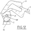
- the control lever 8 can then be pivoted in turn (for example to move away from the body) to move the mechanism 18, 13 a little further (second stroke) cf. figure 12 .
- This second stroke makes it possible to separate the second valve 7 (ball) from its seat (via the end of the first valve 6).
- circuit 3 is more open (totally, first opening section S1). This allows the gas a large flow and a faster rise in pressure downstream of the valves.
- the actuating lever 9 when the control lever 8 is raised (active position) the actuating lever 9 can (or possibly must) also be raised. Of course, as a variant, the actuating lever 9 could remain in the low position (close to the body when the control lever 8 is raised to the active position).
- the two valves 6, 7 are controlled by at least one and the same movable pusher 18, 13.
- This movement transmission mechanism can be translated by two different strokes, one short allowing a limited flow (second opening section S2), the other long allowing full flow (first opening section S1).
- lever mechanisms 8, 9 can be replaced by rotary handwheels or the like.
- cam or cams 14, 15 could be actuated by rotary handwheels.
- the two strokes of the motion transmission mechanism can be driven by cams with axes of rotation 21, 19 of the levers 8, 9 which are identical (combined) or separate.
- the complete (re) closing of the two valves 6, 7 can be achieved in a single gesture which makes it possible to neutralize the two valves 6, 7 in the same manual action.
- a mechanism for coupling the movement of the control member 8 and the actuator 9 can be integrated into the cams 14, 15 of the levers.
- an axis 21 integral with at least one cam 28 can be received in at least one groove 100 formed in the other cam 15 and accommodating and guiding the axis 21.
- the locking mechanism could be integrated at the level of the cams 14, 15 via a system of pins 21 and grooves of the same type as that of the coupling mechanism.
- this locking mechanism for the control member 8 could be located elsewhere on the valve.
- this locking mechanism could be of the magnetic and / or pneumatic and / or electromechanical and / or hydraulic type.
- This faucet structure also allows other functionality for the user.
- the brief actuation only of the actuator 9 allows the user to generate a sufficient and controlled gas jet to purge / clean the downstream side of the circuit 3 and in particular the outlet connection. This is notably a measure recommended by the manufacturers of faucets.
Landscapes
- Engineering & Computer Science (AREA)
- General Engineering & Computer Science (AREA)
- Mechanical Engineering (AREA)
- Chemical & Material Sciences (AREA)
- Analytical Chemistry (AREA)
- Physics & Mathematics (AREA)
- Fluid Mechanics (AREA)
- Preventing Unauthorised Actuation Of Valves (AREA)
- Mechanically-Actuated Valves (AREA)
Priority Applications (1)
| Application Number | Priority Date | Filing Date | Title |
|---|---|---|---|
| PL18762579T PL3692287T3 (pl) | 2017-10-05 | 2018-08-02 | Zawór i zbiornik(i) płynu pod ciśnieniem |
Applications Claiming Priority (3)
| Application Number | Priority Date | Filing Date | Title |
|---|---|---|---|
| FR1701025A FR3072152B1 (fr) | 2017-10-05 | 2017-10-05 | Robinet et reservoir (s) de fluide sous pression |
| FR1701024A FR3072151B1 (fr) | 2017-10-05 | 2017-10-05 | Robinet et reservoir (s) pour fluide sous pression |
| PCT/FR2018/052003 WO2019068975A1 (fr) | 2017-10-05 | 2018-08-02 | Robinet et réservoir(s) de fluide sous pression |
Publications (2)
| Publication Number | Publication Date |
|---|---|
| EP3692287A1 EP3692287A1 (fr) | 2020-08-12 |
| EP3692287B1 true EP3692287B1 (fr) | 2021-09-29 |
Family
ID=63449490
Family Applications (7)
| Application Number | Title | Priority Date | Filing Date |
|---|---|---|---|
| EP18762579.3A Active EP3692287B1 (fr) | 2017-10-05 | 2018-08-02 | Robinet et réservoir(s) de fluide sous pression |
| EP18762577.7A Active EP3692285B1 (fr) | 2017-10-05 | 2018-08-02 | Robinet et réservoir(s) de fluide sous pression |
| EP18785693.5A Active EP3692291B1 (fr) | 2017-10-05 | 2018-08-02 | Robinet et réservoir(s) de fluide sous pression |
| EP18779739.4A Active EP3692289B1 (fr) | 2017-10-05 | 2018-08-02 | Robinet et dispositif de stockage et de distribution de fluide sous pression |
| EP18762578.5A Active EP3692286B1 (fr) | 2017-10-05 | 2018-08-02 | Robinet et réservoir(s) de fluide sous pression |
| EP18780172.5A Active EP3692290B1 (fr) | 2017-10-05 | 2018-08-02 | Robinet et dispositif de stockage et de distribution de fluide sous pression |
| EP18762581.9A Active EP3692288B1 (fr) | 2017-10-05 | 2018-08-02 | Robinet et réservoir(s) de fluide sous pression |
Family Applications After (6)
| Application Number | Title | Priority Date | Filing Date |
|---|---|---|---|
| EP18762577.7A Active EP3692285B1 (fr) | 2017-10-05 | 2018-08-02 | Robinet et réservoir(s) de fluide sous pression |
| EP18785693.5A Active EP3692291B1 (fr) | 2017-10-05 | 2018-08-02 | Robinet et réservoir(s) de fluide sous pression |
| EP18779739.4A Active EP3692289B1 (fr) | 2017-10-05 | 2018-08-02 | Robinet et dispositif de stockage et de distribution de fluide sous pression |
| EP18762578.5A Active EP3692286B1 (fr) | 2017-10-05 | 2018-08-02 | Robinet et réservoir(s) de fluide sous pression |
| EP18780172.5A Active EP3692290B1 (fr) | 2017-10-05 | 2018-08-02 | Robinet et dispositif de stockage et de distribution de fluide sous pression |
| EP18762581.9A Active EP3692288B1 (fr) | 2017-10-05 | 2018-08-02 | Robinet et réservoir(s) de fluide sous pression |
Country Status (10)
| Country | Link |
|---|---|
| US (7) | US11644119B2 (pl) |
| EP (7) | EP3692287B1 (pl) |
| CN (1) | CN111183310B (pl) |
| AU (1) | AU2018346467B2 (pl) |
| CA (7) | CA3078535A1 (pl) |
| DK (4) | DK3692291T3 (pl) |
| ES (5) | ES2904918T3 (pl) |
| PL (4) | PL3692286T3 (pl) |
| PT (2) | PT3692286T (pl) |
| WO (8) | WO2019068970A1 (pl) |
Families Citing this family (10)
| Publication number | Priority date | Publication date | Assignee | Title |
|---|---|---|---|---|
| EP3692287B1 (fr) * | 2017-10-05 | 2021-09-29 | L'air Liquide, Société Anonyme Pour L'Étude Et L'exploitation Des Procédés Georges Claude | Robinet et réservoir(s) de fluide sous pression |
| WO2020060961A1 (en) * | 2018-09-17 | 2020-03-26 | Carrier Corporation | Calibrated gauge tool for checking pressures on installed inert systems per nfpa |
| FR3092894B1 (fr) * | 2019-02-20 | 2021-10-15 | Air Liquide | Dispositif de fourniture de fluide sous pression et bouteille(s) de fluide sous pression comprenant un tel dispositif |
| LU101208B1 (en) * | 2019-04-26 | 2020-10-26 | Luxembourg Patent Co | Lever valve with securing hook |
| US11454328B2 (en) * | 2019-09-10 | 2022-09-27 | Jeffrey Allen Bertrem | Industrial high pressure hand valve |
| US11692672B2 (en) * | 2020-12-17 | 2023-07-04 | Lockheed Martin Corporation | Pressure relief shipping adapter for a bottle head assembly |
| IT202100015410A1 (it) | 2021-06-11 | 2022-12-11 | Cavagna Group Spa | Valvola per fluidi in pressione |
| DE102021130250A1 (de) * | 2021-11-19 | 2023-05-25 | Bayerische Motoren Werke Aktiengesellschaft | Ventilbaugruppe, Druckbehältersystem, Fahrzeug und Verfahren zum Ablassen von Brennstoff |
| FR3132556B1 (fr) | 2022-02-04 | 2024-01-19 | Air Liquide | Vanne pour fluide sous pression, et réservoir ou ensemble de réservoirs de fluide sous pression |
| US12292126B2 (en) * | 2023-06-07 | 2025-05-06 | Scott Wu | Inflator valve connector |
Family Cites Families (55)
| Publication number | Priority date | Publication date | Assignee | Title |
|---|---|---|---|---|
| US294674A (en) * | 1884-03-04 | Water and steam cock or faucet | ||
| US1318120A (en) * | 1919-10-07 | Faucet-nozzle | ||
| US1160285A (en) * | 1915-04-05 | 1915-11-16 | Clement Hobbs | Blow-off cock. |
| US1395678A (en) * | 1919-08-14 | 1921-11-01 | Lawrence R Jones | Valve-lock |
| US1943843A (en) * | 1931-04-27 | 1934-01-16 | Reginald C Shand | Dispensing apparatus |
| US1944456A (en) * | 1931-09-21 | 1934-01-23 | Carl A Pearson | Valve construction |
| GB441279A (en) | 1934-07-16 | 1936-01-16 | Lyons & Co Ltd J | Improvements in or relating to taps for controlling the flow of liquids |
| US2336282A (en) * | 1942-09-11 | 1943-12-07 | Kerotest Mfg Company | Valve |
| US2620817A (en) * | 1947-06-20 | 1952-12-09 | Bastian Blessing Co | Unloading adapter |
| US2709452A (en) * | 1951-04-02 | 1955-05-31 | J Dan Fiorito | Valve interlock mechanism |
| US2830784A (en) * | 1954-09-30 | 1958-04-15 | Placette Theodore | General purpose flow valve with alternative fluid pressure or manual control |
| NL209722A (pl) * | 1955-08-22 | |||
| GB834759A (en) * | 1958-08-15 | 1960-05-11 | Eclipse Copper Company Of York | Improvements in fluid control valves |
| GB1211474A (en) * | 1968-03-13 | 1970-11-04 | Veb Zek | Combined selector and control valve unit for hydraulic lifting and lowering devices |
| US3737140A (en) * | 1971-09-07 | 1973-06-05 | Ellis Corp | Dual controlled valve assembly |
| US4181152A (en) * | 1978-03-06 | 1980-01-01 | The United States Of America As Represented By The Secretary Of The Navy | Control manifold |
| US4429711A (en) * | 1982-03-08 | 1984-02-07 | Anderson, Greenwood & Co. | Multivalve manifold interlock and control system |
| SE442544B (sv) * | 1984-09-17 | 1986-01-13 | Spiromec Ab | Fyllningsventil for fyllning av gasflaskor |
| US4911403A (en) * | 1989-06-22 | 1990-03-27 | Nea Technologies | Pressure responsive two-way shut-off valve |
| FR2664962B1 (fr) * | 1990-07-17 | 1992-09-18 | Air Liquide | Dispositif adaptateur-detendeur de distribution de gaz pour conteneurs de gaz a haute pression. |
| US5421380A (en) * | 1994-03-16 | 1995-06-06 | Campbell; Michael C. | Gas tank evacuator |
| JP3244381B2 (ja) * | 1994-05-11 | 2002-01-07 | 昭和炭酸株式会社 | 弁装置 |
| DE4419545C1 (de) * | 1994-06-03 | 1996-02-22 | Pfannenschmidt Erhard | Vorrichtung zum gemeinsamen Schalten von zwei Armaturen |
| AU691270B2 (en) * | 1994-06-24 | 1998-05-14 | Kabushiki Kaisha Neriki | Valve assembly for gas cylinder |
| US5836352A (en) * | 1996-06-06 | 1998-11-17 | Pgi International, Ltd. | Environmental fill valve |
| DE19648114A1 (de) * | 1996-11-21 | 1998-05-28 | Grohe Armaturen Friedrich | Eingriffmischventil |
| LU90017B1 (fr) * | 1997-01-31 | 1997-06-13 | Luxembourg Patent Company | Robinet à gaz |
| DE19803524A1 (de) | 1998-01-30 | 1999-08-05 | Grohe Armaturen Friedrich | Betätigungseinrichtung für ein Wasserventil |
| US6086045A (en) | 1998-05-27 | 2000-07-11 | Clover Co., Ltd. | Tap with safety mechanism |
| ES1042466Y (es) * | 1999-02-25 | 2000-01-16 | Cepex S A | Valvula. |
| FR2793297A1 (fr) | 1999-05-07 | 2000-11-10 | Air Liquide | Robinet pour recipient de fluide a commande par levier |
| CN2451829Y (zh) * | 2000-11-13 | 2001-10-03 | 于乔治 | 安全水龙头 |
| FR2828922B1 (fr) | 2001-08-23 | 2004-06-11 | Air Liquide | Robinet de controle du debit d'un fluide equipe d'un levier a plusieurs positions stables |
| FR2840664B1 (fr) | 2002-06-05 | 2004-07-09 | Air Liquide | Robinet pour gaz haute pression actionne par un levier adaptable a differentes tetes de bouteilles |
| US7748402B2 (en) * | 2004-10-28 | 2010-07-06 | Fester Assets Corporation | Valve assembly |
| FR2878313B1 (fr) * | 2004-11-25 | 2007-02-16 | Senior Aerospace Ermeto | Ensemble de distribution et de remplissage controle d'une bouteille de gaz sous pression |
| US20060175569A1 (en) * | 2005-02-03 | 2006-08-10 | Terry Henson | Automatic lock for ball valve |
| DE102005057818A1 (de) * | 2005-12-03 | 2007-06-06 | Westo Hydraulik Gmbh | Absperrvorrichtung, insbesondere für Druckleitungen |
| FR2900455B1 (fr) * | 2006-04-26 | 2008-07-04 | Valeo Sys Controle Moteur Sas | Vanne a deux papillons actionnes par un moteur commun |
| FR2914385B1 (fr) * | 2007-03-29 | 2009-07-03 | Taema | Robinet pour bouteille de gaz sous pression |
| GB0806530D0 (en) * | 2008-04-10 | 2008-05-14 | Boc Group Plc | Tamper-resistant valve and connection arrangement |
| CN102906478A (zh) * | 2010-04-08 | 2013-01-30 | 阿尔特拉弗洛股份有限公司 | 具有提高强度的凹槽板的阀 |
| EP2558834B1 (en) * | 2010-04-15 | 2020-04-01 | Swagelok Company | Process interface valve assembly |
| US9010721B2 (en) * | 2011-02-01 | 2015-04-21 | Hayward Industries, Inc. | Valve switchbox |
| US8955823B2 (en) * | 2011-04-07 | 2015-02-17 | Pgi International, Ltd. | Cam operated valve |
| FR2974402B1 (fr) * | 2011-04-22 | 2013-05-03 | Air Liquide | Robinet de fluide sous pression, reservoir et procede de remplissage correspondants |
| US9095955B2 (en) * | 2012-08-16 | 2015-08-04 | Omax Corporation | Control valves for waterjet systems and related devices, systems and methods |
| GB2514358A (en) * | 2013-05-20 | 2014-11-26 | Linde Ag | A pressurised fluid container |
| GB2515561A (en) * | 2013-06-28 | 2014-12-31 | Linde Ag | A pressurised container valve |
| EP3062005B1 (en) | 2015-02-24 | 2018-10-24 | L'AIR LIQUIDE, Société Anonyme pour l'Etude et l'Exploitation des Procédés Georges Claude | Pressurized fluid cylinder tap and a cylinder comprising such a tap |
| FR3033386B1 (fr) * | 2015-03-04 | 2017-10-27 | Air Liquide | Robinet, recipient et procedes de remplissage, de soutirage et de mise sous vide |
| FR3033388B1 (fr) * | 2015-03-04 | 2017-10-27 | Air Liquide | Dispositif de fourniture de fluide sous pression |
| GB201504448D0 (en) * | 2015-03-17 | 2015-04-29 | Linde Ag | A lever-type shut-off valve |
| US9969605B2 (en) * | 2015-04-15 | 2018-05-15 | Acd, Llc | Liquid natural gas gun-style nozzle |
| EP3692287B1 (fr) * | 2017-10-05 | 2021-09-29 | L'air Liquide, Société Anonyme Pour L'Étude Et L'exploitation Des Procédés Georges Claude | Robinet et réservoir(s) de fluide sous pression |
-
2018
- 2018-08-02 EP EP18762579.3A patent/EP3692287B1/fr active Active
- 2018-08-02 ES ES18785693T patent/ES2904918T3/es active Active
- 2018-08-02 WO PCT/FR2018/051994 patent/WO2019068970A1/fr not_active Ceased
- 2018-08-02 PL PL18762578T patent/PL3692286T3/pl unknown
- 2018-08-02 ES ES18762578T patent/ES2890816T3/es active Active
- 2018-08-02 PL PL18785693T patent/PL3692291T3/pl unknown
- 2018-08-02 EP EP18762577.7A patent/EP3692285B1/fr active Active
- 2018-08-02 EP EP18785693.5A patent/EP3692291B1/fr active Active
- 2018-08-02 CA CA3078535A patent/CA3078535A1/en active Pending
- 2018-08-02 DK DK18785693.5T patent/DK3692291T3/da active
- 2018-08-02 PT PT187625785T patent/PT3692286T/pt unknown
- 2018-08-02 US US16/753,259 patent/US11644119B2/en active Active
- 2018-08-02 CA CA3078533A patent/CA3078533A1/en active Pending
- 2018-08-02 WO PCT/FR2018/052000 patent/WO2019068972A1/fr not_active Ceased
- 2018-08-02 DK DK18762579.3T patent/DK3692287T3/da active
- 2018-08-02 EP EP18779739.4A patent/EP3692289B1/fr active Active
- 2018-08-02 WO PCT/FR2018/052003 patent/WO2019068975A1/fr not_active Ceased
- 2018-08-02 CA CA3078527A patent/CA3078527A1/en active Pending
- 2018-08-02 EP EP18762578.5A patent/EP3692286B1/fr active Active
- 2018-08-02 US US16/652,922 patent/US11560966B2/en active Active
- 2018-08-02 PL PL18762579T patent/PL3692287T3/pl unknown
- 2018-08-02 WO PCT/FR2018/052001 patent/WO2019068973A1/fr not_active Ceased
- 2018-08-02 CA CA3078592A patent/CA3078592A1/en active Pending
- 2018-08-02 US US16/753,306 patent/US11313490B2/en active Active
- 2018-08-02 WO PCT/FR2018/051995 patent/WO2019068971A1/fr not_active Ceased
- 2018-08-02 CA CA3078518A patent/CA3078518A1/en active Pending
- 2018-08-02 CN CN201880063664.9A patent/CN111183310B/zh active Active
- 2018-08-02 WO PCT/FR2018/052004 patent/WO2019068976A1/fr not_active Ceased
- 2018-08-02 US US16/652,903 patent/US11555556B2/en active Active
- 2018-08-02 ES ES18780172T patent/ES2898761T3/es active Active
- 2018-08-02 DK DK18762578.5T patent/DK3692286T3/da active
- 2018-08-02 US US16/753,080 patent/US11333267B2/en active Active
- 2018-08-02 ES ES18762579T patent/ES2898758T3/es active Active
- 2018-08-02 PL PL18779739T patent/PL3692289T3/pl unknown
- 2018-08-02 US US16/753,289 patent/US11346462B2/en active Active
- 2018-08-02 WO PCT/FR2018/052002 patent/WO2019068974A1/fr not_active Ceased
- 2018-08-02 US US16/652,863 patent/US11408535B2/en active Active
- 2018-08-02 AU AU2018346467A patent/AU2018346467B2/en active Active
- 2018-08-02 WO PCT/FR2018/052005 patent/WO2019068977A1/fr not_active Ceased
- 2018-08-02 PT PT187856935T patent/PT3692291T/pt unknown
- 2018-08-02 CA CA3078531A patent/CA3078531A1/en active Pending
- 2018-08-02 DK DK18779739.4T patent/DK3692289T3/da active
- 2018-08-02 EP EP18780172.5A patent/EP3692290B1/fr active Active
- 2018-08-02 ES ES18779739T patent/ES2900303T3/es active Active
- 2018-08-02 CA CA3078538A patent/CA3078538A1/en active Pending
- 2018-08-02 EP EP18762581.9A patent/EP3692288B1/fr active Active
Also Published As
Similar Documents
| Publication | Publication Date | Title |
|---|---|---|
| EP3692288B1 (fr) | Robinet et réservoir(s) de fluide sous pression | |
| EP2591273B1 (fr) | Raccord de remplissage, récipient et procédé de remplissage correspondants | |
| EP2591274B1 (fr) | Raccord de remplissage, récipient et procédé de remplissage | |
| EP3708899B1 (fr) | Robinet, récipient de fluide sous pression et procédés de remplissage et de soutirage | |
| EP3693654A1 (fr) | Dispositif de fourniture de fluide sous pression et ensemble de stockage(s) de fluide sous pression comprenant un tel dispositif | |
| FR3072152A1 (fr) | Robinet et reservoir (s) de fluide sous pression | |
| FR3072151A1 (fr) | Robinet et reservoir (s) pour fluide sous pression | |
| EP3296612B1 (fr) | Robinet pour fluide sous pression | |
| EP3978794A1 (fr) | Robinet et dispositif de fourniture de fluide sous pression | |
| BE548753A (pl) |
Legal Events
| Date | Code | Title | Description |
|---|---|---|---|
| STAA | Information on the status of an ep patent application or granted ep patent |
Free format text: STATUS: UNKNOWN |
|
| STAA | Information on the status of an ep patent application or granted ep patent |
Free format text: STATUS: THE INTERNATIONAL PUBLICATION HAS BEEN MADE |
|
| PUAI | Public reference made under article 153(3) epc to a published international application that has entered the european phase |
Free format text: ORIGINAL CODE: 0009012 |
|
| STAA | Information on the status of an ep patent application or granted ep patent |
Free format text: STATUS: REQUEST FOR EXAMINATION WAS MADE |
|
| 17P | Request for examination filed |
Effective date: 20200506 |
|
| AK | Designated contracting states |
Kind code of ref document: A1 Designated state(s): AL AT BE BG CH CY CZ DE DK EE ES FI FR GB GR HR HU IE IS IT LI LT LU LV MC MK MT NL NO PL PT RO RS SE SI SK SM TR |
|
| AX | Request for extension of the european patent |
Extension state: BA ME |
|
| DAV | Request for validation of the european patent (deleted) | ||
| DAX | Request for extension of the european patent (deleted) | ||
| GRAP | Despatch of communication of intention to grant a patent |
Free format text: ORIGINAL CODE: EPIDOSNIGR1 |
|
| STAA | Information on the status of an ep patent application or granted ep patent |
Free format text: STATUS: GRANT OF PATENT IS INTENDED |
|
| INTG | Intention to grant announced |
Effective date: 20210528 |
|
| GRAS | Grant fee paid |
Free format text: ORIGINAL CODE: EPIDOSNIGR3 |
|
| GRAA | (expected) grant |
Free format text: ORIGINAL CODE: 0009210 |
|
| STAA | Information on the status of an ep patent application or granted ep patent |
Free format text: STATUS: THE PATENT HAS BEEN GRANTED |
|
| AK | Designated contracting states |
Kind code of ref document: B1 Designated state(s): AL AT BE BG CH CY CZ DE DK EE ES FI FR GB GR HR HU IE IS IT LI LT LU LV MC MK MT NL NO PL PT RO RS SE SI SK SM TR |
|
| REG | Reference to a national code |
Ref country code: GB Ref legal event code: FG4D Free format text: NOT ENGLISH |
|
| REG | Reference to a national code |
Ref country code: CH Ref legal event code: EP Ref country code: AT Ref legal event code: REF Ref document number: 1434490 Country of ref document: AT Kind code of ref document: T Effective date: 20211015 |
|
| REG | Reference to a national code |
Ref country code: DE Ref legal event code: R096 Ref document number: 602018024343 Country of ref document: DE |
|
| REG | Reference to a national code |
Ref country code: IE Ref legal event code: FG4D Free format text: LANGUAGE OF EP DOCUMENT: FRENCH |
|
| REG | Reference to a national code |
Ref country code: DK Ref legal event code: T3 Effective date: 20211216 |
|
| REG | Reference to a national code |
Ref country code: SE Ref legal event code: TRGR |
|
| REG | Reference to a national code |
Ref country code: LT Ref legal event code: MG9D |
|
| PG25 | Lapsed in a contracting state [announced via postgrant information from national office to epo] |
Ref country code: HR Free format text: LAPSE BECAUSE OF FAILURE TO SUBMIT A TRANSLATION OF THE DESCRIPTION OR TO PAY THE FEE WITHIN THE PRESCRIBED TIME-LIMIT Effective date: 20210929 Ref country code: FI Free format text: LAPSE BECAUSE OF FAILURE TO SUBMIT A TRANSLATION OF THE DESCRIPTION OR TO PAY THE FEE WITHIN THE PRESCRIBED TIME-LIMIT Effective date: 20210929 Ref country code: RS Free format text: LAPSE BECAUSE OF FAILURE TO SUBMIT A TRANSLATION OF THE DESCRIPTION OR TO PAY THE FEE WITHIN THE PRESCRIBED TIME-LIMIT Effective date: 20210929 Ref country code: LT Free format text: LAPSE BECAUSE OF FAILURE TO SUBMIT A TRANSLATION OF THE DESCRIPTION OR TO PAY THE FEE WITHIN THE PRESCRIBED TIME-LIMIT Effective date: 20210929 Ref country code: BG Free format text: LAPSE BECAUSE OF FAILURE TO SUBMIT A TRANSLATION OF THE DESCRIPTION OR TO PAY THE FEE WITHIN THE PRESCRIBED TIME-LIMIT Effective date: 20211229 Ref country code: NO Free format text: LAPSE BECAUSE OF FAILURE TO SUBMIT A TRANSLATION OF THE DESCRIPTION OR TO PAY THE FEE WITHIN THE PRESCRIBED TIME-LIMIT Effective date: 20211229 |
|
| REG | Reference to a national code |
Ref country code: NL Ref legal event code: MP Effective date: 20210929 |
|
| REG | Reference to a national code |
Ref country code: AT Ref legal event code: MK05 Ref document number: 1434490 Country of ref document: AT Kind code of ref document: T Effective date: 20210929 |
|
| PG25 | Lapsed in a contracting state [announced via postgrant information from national office to epo] |
Ref country code: LV Free format text: LAPSE BECAUSE OF FAILURE TO SUBMIT A TRANSLATION OF THE DESCRIPTION OR TO PAY THE FEE WITHIN THE PRESCRIBED TIME-LIMIT Effective date: 20210929 Ref country code: GR Free format text: LAPSE BECAUSE OF FAILURE TO SUBMIT A TRANSLATION OF THE DESCRIPTION OR TO PAY THE FEE WITHIN THE PRESCRIBED TIME-LIMIT Effective date: 20211230 |
|
| REG | Reference to a national code |
Ref country code: ES Ref legal event code: FG2A Ref document number: 2898758 Country of ref document: ES Kind code of ref document: T3 Effective date: 20220308 |
|
| PG25 | Lapsed in a contracting state [announced via postgrant information from national office to epo] |
Ref country code: AT Free format text: LAPSE BECAUSE OF FAILURE TO SUBMIT A TRANSLATION OF THE DESCRIPTION OR TO PAY THE FEE WITHIN THE PRESCRIBED TIME-LIMIT Effective date: 20210929 |
|
| PG25 | Lapsed in a contracting state [announced via postgrant information from national office to epo] |
Ref country code: IS Free format text: LAPSE BECAUSE OF FAILURE TO SUBMIT A TRANSLATION OF THE DESCRIPTION OR TO PAY THE FEE WITHIN THE PRESCRIBED TIME-LIMIT Effective date: 20220129 Ref country code: SK Free format text: LAPSE BECAUSE OF FAILURE TO SUBMIT A TRANSLATION OF THE DESCRIPTION OR TO PAY THE FEE WITHIN THE PRESCRIBED TIME-LIMIT Effective date: 20210929 Ref country code: RO Free format text: LAPSE BECAUSE OF FAILURE TO SUBMIT A TRANSLATION OF THE DESCRIPTION OR TO PAY THE FEE WITHIN THE PRESCRIBED TIME-LIMIT Effective date: 20210929 Ref country code: PT Free format text: LAPSE BECAUSE OF FAILURE TO SUBMIT A TRANSLATION OF THE DESCRIPTION OR TO PAY THE FEE WITHIN THE PRESCRIBED TIME-LIMIT Effective date: 20220131 Ref country code: NL Free format text: LAPSE BECAUSE OF FAILURE TO SUBMIT A TRANSLATION OF THE DESCRIPTION OR TO PAY THE FEE WITHIN THE PRESCRIBED TIME-LIMIT Effective date: 20210929 Ref country code: EE Free format text: LAPSE BECAUSE OF FAILURE TO SUBMIT A TRANSLATION OF THE DESCRIPTION OR TO PAY THE FEE WITHIN THE PRESCRIBED TIME-LIMIT Effective date: 20210929 Ref country code: AL Free format text: LAPSE BECAUSE OF FAILURE TO SUBMIT A TRANSLATION OF THE DESCRIPTION OR TO PAY THE FEE WITHIN THE PRESCRIBED TIME-LIMIT Effective date: 20210929 |
|
| REG | Reference to a national code |
Ref country code: DE Ref legal event code: R097 Ref document number: 602018024343 Country of ref document: DE |
|
| PLBE | No opposition filed within time limit |
Free format text: ORIGINAL CODE: 0009261 |
|
| STAA | Information on the status of an ep patent application or granted ep patent |
Free format text: STATUS: NO OPPOSITION FILED WITHIN TIME LIMIT |
|
| 26N | No opposition filed |
Effective date: 20220630 |
|
| PG25 | Lapsed in a contracting state [announced via postgrant information from national office to epo] |
Ref country code: SI Free format text: LAPSE BECAUSE OF FAILURE TO SUBMIT A TRANSLATION OF THE DESCRIPTION OR TO PAY THE FEE WITHIN THE PRESCRIBED TIME-LIMIT Effective date: 20210929 |
|
| REG | Reference to a national code |
Ref country code: DE Ref legal event code: R119 Ref document number: 602018024343 Country of ref document: DE |
|
| PG25 | Lapsed in a contracting state [announced via postgrant information from national office to epo] |
Ref country code: MC Free format text: LAPSE BECAUSE OF FAILURE TO SUBMIT A TRANSLATION OF THE DESCRIPTION OR TO PAY THE FEE WITHIN THE PRESCRIBED TIME-LIMIT Effective date: 20210929 |
|
| REG | Reference to a national code |
Ref country code: CH Ref legal event code: PL |
|
| PG25 | Lapsed in a contracting state [announced via postgrant information from national office to epo] |
Ref country code: LU Free format text: LAPSE BECAUSE OF NON-PAYMENT OF DUE FEES Effective date: 20220802 Ref country code: LI Free format text: LAPSE BECAUSE OF NON-PAYMENT OF DUE FEES Effective date: 20220831 Ref country code: CH Free format text: LAPSE BECAUSE OF NON-PAYMENT OF DUE FEES Effective date: 20220831 |
|
| REG | Reference to a national code |
Ref country code: BE Ref legal event code: MM Effective date: 20220831 |
|
| PG25 | Lapsed in a contracting state [announced via postgrant information from national office to epo] |
Ref country code: IE Free format text: LAPSE BECAUSE OF NON-PAYMENT OF DUE FEES Effective date: 20220802 Ref country code: DE Free format text: LAPSE BECAUSE OF NON-PAYMENT OF DUE FEES Effective date: 20230301 |
|
| PG25 | Lapsed in a contracting state [announced via postgrant information from national office to epo] |
Ref country code: BE Free format text: LAPSE BECAUSE OF NON-PAYMENT OF DUE FEES Effective date: 20220831 |
|
| P01 | Opt-out of the competence of the unified patent court (upc) registered |
Effective date: 20230825 |
|
| PG25 | Lapsed in a contracting state [announced via postgrant information from national office to epo] |
Ref country code: SM Free format text: LAPSE BECAUSE OF FAILURE TO SUBMIT A TRANSLATION OF THE DESCRIPTION OR TO PAY THE FEE WITHIN THE PRESCRIBED TIME-LIMIT Effective date: 20210929 Ref country code: MK Free format text: LAPSE BECAUSE OF FAILURE TO SUBMIT A TRANSLATION OF THE DESCRIPTION OR TO PAY THE FEE WITHIN THE PRESCRIBED TIME-LIMIT Effective date: 20210929 Ref country code: CY Free format text: LAPSE BECAUSE OF FAILURE TO SUBMIT A TRANSLATION OF THE DESCRIPTION OR TO PAY THE FEE WITHIN THE PRESCRIBED TIME-LIMIT Effective date: 20210929 |
|
| PG25 | Lapsed in a contracting state [announced via postgrant information from national office to epo] |
Ref country code: HU Free format text: LAPSE BECAUSE OF FAILURE TO SUBMIT A TRANSLATION OF THE DESCRIPTION OR TO PAY THE FEE WITHIN THE PRESCRIBED TIME-LIMIT; INVALID AB INITIO Effective date: 20180802 |
|
| PG25 | Lapsed in a contracting state [announced via postgrant information from national office to epo] |
Ref country code: MT Free format text: LAPSE BECAUSE OF FAILURE TO SUBMIT A TRANSLATION OF THE DESCRIPTION OR TO PAY THE FEE WITHIN THE PRESCRIBED TIME-LIMIT Effective date: 20210929 |
|
| PGFP | Annual fee paid to national office [announced via postgrant information from national office to epo] |
Ref country code: CZ Payment date: 20240725 Year of fee payment: 7 |
|
| PGFP | Annual fee paid to national office [announced via postgrant information from national office to epo] |
Ref country code: ES Payment date: 20250926 Year of fee payment: 8 |
|
| PGFP | Annual fee paid to national office [announced via postgrant information from national office to epo] |
Ref country code: DK Payment date: 20250825 Year of fee payment: 8 |
|
| PGFP | Annual fee paid to national office [announced via postgrant information from national office to epo] |
Ref country code: TR Payment date: 20250728 Year of fee payment: 8 Ref country code: PL Payment date: 20250725 Year of fee payment: 8 Ref country code: IT Payment date: 20250820 Year of fee payment: 8 |
|
| PGFP | Annual fee paid to national office [announced via postgrant information from national office to epo] |
Ref country code: GB Payment date: 20250820 Year of fee payment: 8 |
|
| PGFP | Annual fee paid to national office [announced via postgrant information from national office to epo] |
Ref country code: FR Payment date: 20250828 Year of fee payment: 8 |
|
| PGFP | Annual fee paid to national office [announced via postgrant information from national office to epo] |
Ref country code: SE Payment date: 20250820 Year of fee payment: 8 |
|
| PG25 | Lapsed in a contracting state [announced via postgrant information from national office to epo] |
Ref country code: CZ Free format text: LAPSE BECAUSE OF NON-PAYMENT OF DUE FEES Effective date: 20250802 |