EP3691230A1 - Outer frame, terminal housing and terminal - Google Patents
Outer frame, terminal housing and terminal Download PDFInfo
- Publication number
- EP3691230A1 EP3691230A1 EP19215333.6A EP19215333A EP3691230A1 EP 3691230 A1 EP3691230 A1 EP 3691230A1 EP 19215333 A EP19215333 A EP 19215333A EP 3691230 A1 EP3691230 A1 EP 3691230A1
- Authority
- EP
- European Patent Office
- Prior art keywords
- light
- outer frame
- transmitting
- terminal
- transmitting member
- Prior art date
- Legal status (The legal status is an assumption and is not a legal conclusion. Google has not performed a legal analysis and makes no representation as to the accuracy of the status listed.)
- Pending
Links
Images




Classifications
-
- H—ELECTRICITY
- H04—ELECTRIC COMMUNICATION TECHNIQUE
- H04M—TELEPHONIC COMMUNICATION
- H04M1/00—Substation equipment, e.g. for use by subscribers
- H04M1/02—Constructional features of telephone sets
- H04M1/0202—Portable telephone sets, e.g. cordless phones, mobile phones or bar type handsets
- H04M1/026—Details of the structure or mounting of specific components
-
- H—ELECTRICITY
- H04—ELECTRIC COMMUNICATION TECHNIQUE
- H04W—WIRELESS COMMUNICATION NETWORKS
- H04W88/00—Devices specially adapted for wireless communication networks, e.g. terminals, base stations or access point devices
- H04W88/02—Terminal devices
- H04W88/06—Terminal devices adapted for operation in multiple networks or having at least two operational modes, e.g. multi-mode terminals
-
- H—ELECTRICITY
- H05—ELECTRIC TECHNIQUES NOT OTHERWISE PROVIDED FOR
- H05K—PRINTED CIRCUITS; CASINGS OR CONSTRUCTIONAL DETAILS OF ELECTRIC APPARATUS; MANUFACTURE OF ASSEMBLAGES OF ELECTRICAL COMPONENTS
- H05K5/00—Casings, cabinets or drawers for electric apparatus
- H05K5/02—Details
- H05K5/0217—Mechanical details of casings
-
- G—PHYSICS
- G06—COMPUTING OR CALCULATING; COUNTING
- G06F—ELECTRIC DIGITAL DATA PROCESSING
- G06F1/00—Details not covered by groups G06F3/00 - G06F13/00 and G06F21/00
- G06F1/16—Constructional details or arrangements
- G06F1/1613—Constructional details or arrangements for portable computers
- G06F1/1626—Constructional details or arrangements for portable computers with a single-body enclosure integrating a flat display, e.g. Personal Digital Assistants [PDAs]
-
- G—PHYSICS
- G06—COMPUTING OR CALCULATING; COUNTING
- G06F—ELECTRIC DIGITAL DATA PROCESSING
- G06F1/00—Details not covered by groups G06F3/00 - G06F13/00 and G06F21/00
- G06F1/16—Constructional details or arrangements
- G06F1/1613—Constructional details or arrangements for portable computers
- G06F1/1633—Constructional details or arrangements of portable computers not specific to the type of enclosures covered by groups G06F1/1615 - G06F1/1626
- G06F1/1656—Details related to functional adaptations of the enclosure, e.g. to provide protection against EMI, shock, water, or to host detachable peripherals like a mouse or removable expansions units like PCMCIA cards, or to provide access to internal components for maintenance or to removable storage supports like CDs or DVDs, or to mechanically mount accessories
-
- G—PHYSICS
- G06—COMPUTING OR CALCULATING; COUNTING
- G06F—ELECTRIC DIGITAL DATA PROCESSING
- G06F1/00—Details not covered by groups G06F3/00 - G06F13/00 and G06F21/00
- G06F1/16—Constructional details or arrangements
- G06F1/1613—Constructional details or arrangements for portable computers
- G06F1/1633—Constructional details or arrangements of portable computers not specific to the type of enclosures covered by groups G06F1/1615 - G06F1/1626
- G06F1/1684—Constructional details or arrangements related to integrated I/O peripherals not covered by groups G06F1/1635 - G06F1/1675
-
- G—PHYSICS
- G06—COMPUTING OR CALCULATING; COUNTING
- G06F—ELECTRIC DIGITAL DATA PROCESSING
- G06F1/00—Details not covered by groups G06F3/00 - G06F13/00 and G06F21/00
- G06F1/16—Constructional details or arrangements
- G06F1/1613—Constructional details or arrangements for portable computers
- G06F1/1633—Constructional details or arrangements of portable computers not specific to the type of enclosures covered by groups G06F1/1615 - G06F1/1626
- G06F1/1684—Constructional details or arrangements related to integrated I/O peripherals not covered by groups G06F1/1635 - G06F1/1675
- G06F1/1686—Constructional details or arrangements related to integrated I/O peripherals not covered by groups G06F1/1635 - G06F1/1675 the I/O peripheral being an integrated camera
-
- H—ELECTRICITY
- H04—ELECTRIC COMMUNICATION TECHNIQUE
- H04W—WIRELESS COMMUNICATION NETWORKS
- H04W52/00—Power management, e.g. Transmission Power Control [TPC] or power classes
- H04W52/02—Power saving arrangements
- H04W52/0209—Power saving arrangements in terminal devices
- H04W52/0251—Power saving arrangements in terminal devices using monitoring of local events, e.g. events related to user activity
-
- G—PHYSICS
- G06—COMPUTING OR CALCULATING; COUNTING
- G06F—ELECTRIC DIGITAL DATA PROCESSING
- G06F1/00—Details not covered by groups G06F3/00 - G06F13/00 and G06F21/00
- G06F1/16—Constructional details or arrangements
- G06F1/1613—Constructional details or arrangements for portable computers
- G06F1/163—Wearable computers, e.g. on a belt
-
- G—PHYSICS
- G06—COMPUTING OR CALCULATING; COUNTING
- G06F—ELECTRIC DIGITAL DATA PROCESSING
- G06F2200/00—Indexing scheme relating to G06F1/04 - G06F1/32
- G06F2200/16—Indexing scheme relating to G06F1/16 - G06F1/18
- G06F2200/163—Indexing scheme relating to constructional details of the computer
- G06F2200/1633—Protecting arrangement for the entire housing of the computer
-
- H—ELECTRICITY
- H04—ELECTRIC COMMUNICATION TECHNIQUE
- H04M—TELEPHONIC COMMUNICATION
- H04M2250/00—Details of telephonic subscriber devices
- H04M2250/12—Details of telephonic subscriber devices including a sensor for measuring a physical value, e.g. temperature or motion
Definitions
- the present disclosure relates to electronic device technologies, and more particularly, to an outer frame, a terminal housing and a terminal.
- a terminal is provided with a variety of functional modules to realize various functions.
- the functional modules are disposed on the front side of the terminal.
- an operating surface of the functional modules for receiving or transmitting signals is located on a display side of the terminal.
- the present disclosure relates to electronic device technologies, and more particularly, to an outer frame, a terminal housing and a terminal.
- an outer frame comprising:
- the light-transmitting member has a higher absorptivity or reflectivity of the incident light than its light transmittance of the incident light.
- the outer frame comprises: a transparent substrate and a light-transmitting and shielding layer disposed on the transparent substrate, wherein the light-transmitting and shielding layer at least partially absorbs or reflects light.
- the light-transmitting and shielding layer is coated on a surface of the transparent substrate, or is sandwiched between two transparent substrates.
- the light-transmitting structure comprises at least one of:
- the light-transmitting member blocks or covers the open pore structure or the structure having the light-transmitting slit in the outer frame, and the light-transmitting member is aligned with the open pore structure or a region around the light-transmitting slit.
- the light-transmitting member comprises a two-way mirror, also called a semi-transparent mirror.
- a terminal housing comprising: at least one of side edges, a rear cover and a front cover; wherein the side edges and the rear cover are enclosed to form a cavity; and the terminal housing further comprises the outer frame according to the first aspect.
- the terminal housing further comprises: a support member which is connected to the outer frame, and is not light transmissive.
- the support member comprises an abutment surface recessed toward outside of the terminal housing; and the outer frame comprises a laterally extending abutting surface which abuts against the abutment surface.
- a terminal comprising: a photosensor and the outer frame according to the first aspect or the terminal housing according to the second aspect; wherein a photosensitive surface of the photosensor is disposed corresponding to the transparent member.
- the outer frame comprises a screen frame in which a light-transmitting structure is formed, the light-transmitting member being disposed corresponding to the light-transmitting structure; and the terminal further comprises a photosensor disposed corresponding to the light-transmitting member in the screen frame.
- the photosensor is selected from at least one of a structured light module, an optical fingerprint recognition module, an optical distance monitoring module and a camera module.
- the outer frame provided by the embodiments of the present disclosure allows light to pass through its light-transmitting member. Therefore, when the outer frame and the photosensor are assembled, the light that passes through the light-transmitting member is received by the photosensor to keep the photosensor working. Moreover, the light-transmitting member plays a role in shielding by at least partially absorbing or reflecting light, so the shielding effect of the outer frame is realized.
- the outer frame provided by the embodiments of the present disclosure reduces open pores on the outer frame because of the light-transmitting member, which not only improves the structure stability of the outer frame but also simplifies its manufacturing processes.
- the inventors have recognized that it is difficult to allow a functional module having a photosensor to be disposed corresponding to an outer frame in the relevant technologies. Specifically, since the photosensor operates based on an optical signal, when the functional module having the photosensor is disposed corresponding to the outer frame, a light-transmitting hole needs to be formed on the outer frame, which corresponds to a photosensitive surface of the photosensor.
- the terminal usually has a thin thickness, so its outer frame has a small height.
- the opening of the light-transmitting hole in the outer frame easily affects the mechanical stability of the outer frame and there may not be enough space for the forming a hole, which all increase the difficulty in providing the functional module having the photosensor on the side edge of the terminal.
- the terminal can be a mobile phone, a tablet computer or a wearable device. Descriptions will be made by taking side edges and mobile phones for example in the following drawings.
- an embodiment of the present disclosure provides an outer frame 1.
- the outer frame 1 includes a light-transmitting structure, which is a structure that allows light to pass therethrough.
- the outer frame 1 further includes a light-transmitting member 11 disposed corresponding to the light-transmitting structure.
- a portion of the outer frame 1 that corresponds to the light-transmitting structure and the light-transmitting member 11 allows light to pass therethrough. Therefore, when in use, a photosensitive surface of a photosensor is optionally disposed corresponding to the light-transmitting member 11 and the normal use of the photosensor is ensured with light passing through the light-transmitting member 11.
- the outer frame 1 includes all the sides of a terminal, which encircles to from a mounting area 12 (as shown in FIG. 1 ) in which a display screen is mounted.
- the outer frame 1 includes part of the sides of a terminal.
- the light-transmitting structure 11 can be implemented by at least one of the following ways.
- the light-transmitting structure 11 is an open pore, a bore or an opening structure in the outer frame 1, generally referred to as open pore structure in the following.
- the light-transmitting structure 11 is a structure having a light-transmitting slit in the outer frame 1, for example, a light-transmitting slit formed at a junction of various components in the outer frame 1.
- the light-transmitting member 11 blocks or covers the open pore structure or the light-transmitting slit in the outer frame 1, so that the outer frame 1 becomes an integral structure. Moreover, the light-transmitting member 11 is aligned with an area around the open pore structure or the light-transmitting slit. Thus, the outer frame 1 will have a continuous structure and its integration effect will be optimized.
- the light-transmitting member 11 will have a planar structure if the open pore structure or the light-transmitting slit of the outer frame 1 is a planar structure; and the light-transmitting member 11 will have a curved surface structure if the open pore structure or the light-transmitting slit of the outer frame 1 is a curved surface structure.
- the outer frame 1 optionally does not include a light-transmitting material, for example, the outer frame 1 is a metal outer frame, a ceramic outer frame, or the like.
- the light-transmitting structure is a structure made of a light-transmitting material in the outer frame 1.
- the middle frame 1 is a transparent middle frame.
- the outer frame 1 includes a transparent portion.
- the outer frame 1 includes a transparent substrate and an opaque film plated on the transparent substrate and a region on the transparent substrate of the outer frame 1 where no opaque film is provided becomes a light-transmitting region.
- a light-transmitting member 11 disposed in the light-transmitting region of the outer frame 1 can allow light to pass therethrough. Therefore, even if the photosensor is placed under the light-transmitting member 11, the light passing through the light-transmitting member 11 allows the photosensor to operate.
- the outer frame 1 meets the needs of the photosensor assembled therewith. Therefore, the structural stability of the outer frame 1 is optimized and its manufacturing processes are simplified.
- the light-transmitting member 11 also has the capability of absorbing or reflecting light. Further, the light-transmitting member 11 at least partially absorbs, reflects or scatters light, so that a luminous flux of light passing through the light-transmitting member 11 is less than that of the incident light in the same direction. Thus, the light-transmitting member 11 can shield the structure under the light-transmitting member 11, and has shielding performance of the outer frame 1.
- the light-transmitting member 11 has a higher absorptivity or reflectivity of the incident light than its light transmittance of the incident light. Accordingly, the shielding property of the light-transmitting member 11 is further enhanced and the terminal's appearance is optimized which meets user requirements.
- the light-transmitting member 11 when the light-transmitting member 11 at least partially absorbs the incident light, among light incident on a side of the light-transmitting member 11, an intensity of light passing through the light-transmitting member 11 is less than that of light absorbed by the light-transmitting member 11. It can be understood that when brightness of ambient light on one side of the light-transmitting member 11 is high while brightness of ambient light on the other side is low, it is difficult to see the other side of the light-transmitting member 11 from the one side with higher brightness of ambient light of the light-transmitting member 11. Namely, the shielding property of the light-transmitting member 11 is achieved.
- the light-transmitting member 11 can be a heat insulating film.
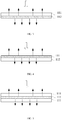
- the reflecting of the incident light by the light-transmitting member 11 referring to FIG. 2 , light is incident on one side of the light-transmitting member 11, in which first light a passes through the light-transmitting member 11 and second light b is reflected by the light-transmitting member 11. Since a reflective index of the light-transmitting member 11 is greater than its light pass-through rate, the second light b has a greater intensity than that of the first light a. It can be understood that when brightness of ambient light on one side of the light-transmitting member 11 is high while brightness of ambient light on the other side is low, it is difficult to see the other side of the light-transmitting member 11 from the one side with higher brightness of ambient light of the light-transmitting member 11. Namely, the shielding property of the light-transmitting member 11 is achieved.
- the light-transmitting member 11 can represent a mirror image on the side with higher brightness of ambient light by the reflected second light b.
- the outer frame 1 represents a mirror image of an external environment of the terminal with the second light b reflected by the light-transmitting member 11, which further improves user experience brought by the screen frame.
- the light-transmitting member 11 can be a two-way mirror.
- the light-transmitting member 11 can be a semi-transparent mirror or also called a partially transparent/reflective mirror.
- An intensity of ambient light inside the terminal is weak, so that the outer frame 1 can have the properties of light-transmitting and shielding and also maintain an integral structure at the same time.
- the outer frame 1 is generally applied to the terminal and its one side faces the inside of the terminal. Obviously, an intensity of ambient light inside the terminal is weaker than that of a space outside the terminal, in which the terminal is used. Therefore, in this case, the outer frame 1 provided by the present disclosure achieves both the properties of light-transmitting and shielding by the light-transmitting member 11.
- the outer frame 1 provided by the embodiment of the present disclosure is characterized by a complete and continuous structure via the light-transmitting member 11, which helps to reduce the number of open pores on the outer frame 1 or leads to a situation in which no light-transmitting hole is opened. Therefore, the structural stability of the outer frame 1 is optimized and manufacturing processes of the outer frame 1 are simplified.
- the outer frame has a seamless structure without an open pore, thereby allowing the terminal such as the mobile phone to have a seamless structure not only visually more pleasing but also can be more water resistant.
- a specific characterization amount of light intensity is not limited, such as illuminance, power, and the like.
- FIGS. 3 - 5 are cross-sectional views illustrating an outer frame according to various exemplary embodiments.
- a transparent member 11 includes a transparent substrate 111 and a light-transmitting and shielding layer 112 disposed on the transparent substrate 111.
- the light-transmitting and shielding layer 112 allows first light a to pass through but reflects second light b.
- the transparent substrate 111 and the light-transmitting and shielding layer 112 can be disposed in optional ways as follows.
- the first way is to coat and dispose the light-transmitting and shielding layer 112 on one side of the transparent substrate 111.
- the light-transmitting and shielding layer 112 is disposed on a surface of the transparent substrate 111 away from a photosensor. Accordingly, the light-transmitting and shielding layer 112 is directly exposed outside and the second light b is reflected without passing through the transparent substrate 111.
- the second way is to coat and dispose the light-transmitting and shielding layer 112 on a surface of the transparent substrate 111 facing the photosensor. Accordingly, the second light b reflected by the light-transmitting and shielding layer 112 passes through the transparent substrate 111 and exits out of the transparent member 11.
- the transparent substrate 111 is optionally a transparent substrate having a predetermined color, at least partially filtering some of the colors, i.e. wavelength. Further, by the reflection of the light-transmitting and shielding layer 112, the transparent member 11 displays a predetermined color, at least partially reflecting some of the colors, i.e. wavelength, so the display effect of the transparent member 11 will be enriched.
- the transparent substrate 111 faces outside of the terminal and the light-transmitting and shielding layer 112 is located inside the terminal, so that the light-transmitting and shielding layer 112 is immune to interference via the transparent substrate 111.
- a light-transmitting frame 11 includes two opposite transparent substrates 111, between which the light-transmitting and shielding layer 112 is disposed.
- the transparent substrates 111 it is ensured that the light-transmitting and shielding layer 112 is immune to interference no matter inside or outside the terminal, and is stably disposed in the transparent substrates 111.
- the transparent substrate 111 on a side of the light-transmitting and shielding layer 112 away from the photosensor is a colored transparent body having a predetermined color, so that the transparent member 11 can display a predetermined color.
- the transparent substrates 111 can be a glass substrate, a resin substrate or the like.
- the light-transmitting and shielding layer 112 can be a resin film layer, a paint layer or a metal layer.
- the light-transmitting and shielding layer 112 is formed on the transparent substrate 111 by plating, spraying or injection molding.
- the transparent member 11 can be integrated and manufactured by double injection molding.
- the transparent member 11 can have a single layer structure, for example, it is a translucent resin plate having a predetermined color.
- the terminal housing includes at least one of a rear cover 21, a side edge 22 and a front cover (not shown, it is a component of a terminal located on one side of a display surface, such as a cover plate or a screen frame).
- the side edge 22 and the rear cover 21 are encircled to form a cavity 23.
- the rear cover 21 and the side edge 22 are integrally formed.
- an outer frame 1 and the rear cover 21 are two detachable components.
- a material of the rear cover 21 is not limited, for example, the rear cover 21 is a ceramic rear cover or a metal rear cover.
- the terminal housing 2 further includes the outer frame 1 according to the first aspect described above.
- at least one of the rear cover 21, the side edge 22 and the front cover includes the outer frame 1.
- the side edge 22 includes the outer frame 1.
- the terminal housing has various types of structures.
- the outer frame 1 is integrally formed on the terminal housing 2.
- the transparent member 11 is part of the outer frame 1.
- the terminal 2 further includes a support member 24 which is connected to the outer frame 1 and is not light-transmissive.
- the opaque support member 24 achieves a high shielding effect, so that a portion of the terminal in which no photosensor is disposed is completely shielded. Moreover, a vision difference between the support member 24 and the transparent member 11 of the outer frame 1 allows a user to know a position of a functional module having a photosensor, so the ease of use of the terminal is increased and user experience is improved.
- modules may have modular configurations, or are composed of discrete components, but nonetheless may be referred to as “modules” or “portions” in general.
- the "components,” “circuits,” “modules,” “units,” “blocks,” or “portions” referred to herein may or may not be in modular forms.
- the support member 24 and the outer frame 11 can be optionally connected in the way as shown in FIG. 9 .
- the support member 24 includes an abutment surface 241 that is recessed toward outside of the outer frame 1.
- the outer frame 1 includes a laterally extending abutment surface 14. When assembled, the abutment surface 14 of the outer frame 1 abuts against the abutment surface 241 of the support member 24.
- the joint of the abutment surface 241 and the abutment surface 14 increases a connection area of the outer frame 1 and the support member 24, so as to improve the connection stability of the outer frame 1 and the support member 24.
- the transparent member 11 is one of side edges of the outer frame 1, or is part of one of the side edges of the outer frame 1.
- the support member 24 is selected from any part of the terminal housing that is connected to the outer frame 1.
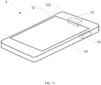
- FIG. 10 is a structural schematic diagram illustrating a terminal according to some embodiments.
- the terminal 3 includes a photosensor 31 and the terminal housing 2 according to the second aspect described above.
- a photosensitive surface of the photosensor 31 is disposed corresponding to the transparent member 11 of the outer frame 1 in the terminal housing 2.
- the number of the photosensors 31 is not limited, but photosensitive surfaces of the photosensors 31 are all disposed corresponding to the transparent member 11.
- a plurality of photosensors 31 can be disposed on the side edges of the terminal by assembling the photosensors 31 and the transparent member 11 in the outer frame 1 to achieve various functions. Moreover, in this case, it is not necessary to provide a plurality of light-transmitting holes, so the structure stability of the outer frame 1 is ensured and functions of the side edges of the terminal 3 are realized. Detailed descriptions will be made hereinafter in conjunction with specific examples.
- the photosensor 31 is a sensor in a distance monitoring module. A distance from a target object outside the terminal to the side edge can be monitored by the photosensor 31.
- the photosensor 31 is a sensor in a fingerprint recognition module.
- a fingerprint feature of a target object at the side edge of the terminal can be identified by the photosensor 31, so as to trigger designated functions such as unlocking, paying or photographing.
- the transparent member 11 covers the photosensors 31 to meet the normal use of the sensors 31.
- the terminal 3 further includes a screen frame 32 which includes the light-transmitting member 321 according to the first aspect described above. Therefore, the terminal 3 optionally further includes a photosensor 33 disposed corresponding to a light-transmitting member 321.
- the light-transmitting member 321 can maintain the structural integrity of the screen frame 32 when it ensures the normal use of the photosensor 33 and the shielding of the photosensor 33. Accordingly, it contributes to reducing open pores on the screen frame 32, improving the structural stability of the screen frame 32 and simplifying production processes of the screen frame 32.
- the photosensor (31, 33) can be selected from sensors of any of the following functional modules: a structured light module, an optical fingerprint recognition module, an optical distance monitoring module and a camera module.
- FIG. 11 is a block diagram of a terminal 600 according to some embodiments of the present disclosure.
- the terminal 600 may be a mobile phone, a computer, a digital broadcast terminal, a messaging device, a gaming console, a tablet, a medical device, exercise equipment, a personal digital assistant and the like.
- the terminal 600 may include one or more of the following components: a processing component 602, a memory 604, a power component 606, a multimedia component 608, an audio component 610, an Input/Output (I/O) interface 612, a sensor component 614, and a communication component 616.
- the processing component 602 typically is configured to control overall operations of the terminal 600, such as the operations associated with display, telephone calls, data communications, camera operations, and recording operations.
- the processing component 602 may include one or more processors 620 to execute instructions to perform all or part of the operations in the abovementioned method.
- the processing component 602 may include one or more portions which facilitate interaction between the processing component 602 and the other components.
- the processing component 602 may include a multimedia portion to facilitate interaction between the multimedia component 608 and the processing component 602.
- the memory 604 is configured to store various types of data to support the operation of the device 600. Examples of such data include instructions for any application programs or methods operated on the terminal 600, contact data, phonebook data, messages, pictures, video, etc.
- the memory 604 may be implemented by any type of volatile or non-volatile memory devices, or a combination thereof, such as an Electrically Erasable Programmable Read-Only Memory (EEPROM), an Erasable Programmable Read-Only Memory (EPROM), a Programmable Read-Only Memory (PROM), a Read-Only Memory (ROM), a magnetic memory, a flash memory, and a magnetic or optical disk.
- EEPROM Electrically Erasable Programmable Read-Only Memory
- EPROM Erasable Programmable Read-Only Memory
- PROM Programmable Read-Only Memory
- ROM Read-Only Memory
- the power component 606 is configured to provide power for various components of the terminal 600.
- the power component 606 may include a power management system, one or more power supplies, and other components associated with generation, management and distribution of power for the terminal 600.
- the multimedia component 608 may include a screen providing an output interface between the terminal 600 and a user.
- the screen may include an LCD and a Touch Panel (TP).
- TP Touch Panel
- OLED organic light-emitting diode
- other types of displays can be employed.
- the screen may be implemented as a touch screen to receive an input signal from the user.
- the TP may include one or more touch sensors to sense touches, swipes and gestures on the TP.
- the touch sensors may not only sense a boundary of a touch or swipe action but also detect a duration and pressure associated with the touch or swipe action.
- the multimedia component 608 may include a front camera and/or a rear camera.
- the front camera and/or the rear camera may receive external multimedia data when the device 600 is in an operation mode, such as a photographing mode or a video mode.
- Each of the front camera and the rear camera may be a fixed optical lens system or have focusing and optical zooming capabilities.
- the audio component 610 is configured to output and/or input an audio signal.
- the audio component 610 may include a Microphone (MIC), and the MIC is configured to receive an external audio signal when the terminal 600 is in the operation mode, such as a call mode, a recording mode and a voice recognition mode.
- the received audio signal may further be stored in the memory 604 or sent through the communication component 616.
- the audio component 610 further may include a speaker configured to output the audio signal.
- the I/O interface 612 is configured to provide an interface between the processing component 602 and a peripheral interface module, and the peripheral interface module may be a keyboard, a click wheel, a button and the like.
- the button may include, but not limited to: a home button, a volume button, a starting button and a locking button.
- the sensor component 614 may include one or more sensors configured to provide status assessment in various aspects for the terminal 600. For instance, the sensor component 614 may detect an on/off status of the device 600 and relative positioning of components, such as a display and small keyboard of the terminal 600, and the sensor component 614 may further detect a change in a position of the terminal 600 or a component of the terminal 600, presence or absence of contact between the user and the terminal 600, orientation or acceleration/deceleration of the terminal 600 and a change in temperature of the terminal 600.
- the sensor component 614 may include a proximity sensor configured to detect presence of an object nearby without any physical contact.
- the sensor component 614 may also include a light sensor, such as a Complementary Metal Oxide Semiconductor (CMOS) or Charge Coupled Device (CCD) image sensor, configured for use in an imaging APP.
- CMOS Complementary Metal Oxide Semiconductor
- CCD Charge Coupled Device
- the sensor component 614 may also include an acceleration sensor, a gyroscope sensor, a magnetic sensor, a pressure sensor or a temperature sensor.
- the communication component 616 is configured to facilitate wired or wireless communication between the terminal 600 and other equipment.
- the terminal 600 may access a communication-standard-based wireless network, such as a Wireless Fidelity (Wi-Fi) network, a 2 nd -Generation (2G), 3 rd -Generation (3G), 4 th -Generation (4G), or 5 th -Generation (5G) network or a combination thereof.
- Wi-Fi Wireless Fidelity
- 2G 2 nd -Generation
- 3G 3 rd -Generation
- 4G 4 th -Generation
- 5G 5 th -Generation
- the outer frame provided by the embodiments of the present disclosure allows light to pass through its light-transmitting member. Therefore, when the outer frame and the photosensor are assembled, the light that passes through the light-transmitting member is received by the photosensor to keep the photosensor working. Moreover, the light-transmitting member plays a role in shielding by absorbing or reflecting light, so the shielding effect of the outer frame is realized.
- the outer frame provided by the embodiments of the present disclosure reduces open pores on the outer frame because of the light-transmitting member, which not only improves the structure stability of the outer frame but also simplifies its manufacturing processes.
- the terms “installed,” “connected,” “coupled,” “fixed” and the like shall be understood broadly, and can be either a fixed connection or a detachable connection, or integrated, unless otherwise explicitly defined. These terms can refer to mechanical or electrical connections, or both. Such connections can be direct connections or indirect connections through an intermediate medium. These terms can also refer to the internal connections or the interactions between elements. The specific meanings of the above terms in the present disclosure can be understood by those of ordinary skill in the art on a case-by-case basis.
- the terms “one embodiment,” “some embodiments,” “example,” “specific example,” or “some examples,” and the like can indicate a specific feature described in connection with the embodiment or example, a structure, a material or feature included in at least one embodiment or example.
- the schematic representation of the above terms is not necessarily directed to the same embodiment or example.
- first and second are used for descriptive purposes only and are not to be construed as indicating or implying a relative importance or implicitly indicating the number of technical features indicated.
- elements referred to as “first” and “second” may include one or more of the features either explicitly or implicitly.
- a plurality indicates two or more unless specifically defined otherwise.
- a first element being "on” a second element may indicate direct contact between the first and second elements, without contact, or indirect geometrical relationship through one or more intermediate media or layers, unless otherwise explicitly stated and defined.
- a first element being “under,” “underneath” or “beneath” a second element may indicate direct contact between the first and second elements, without contact, or indirect geometrical relationship through one or more intermediate media or layers, unless otherwise explicitly stated and defined.
Landscapes
- Engineering & Computer Science (AREA)
- Computer Hardware Design (AREA)
- Theoretical Computer Science (AREA)
- General Engineering & Computer Science (AREA)
- Human Computer Interaction (AREA)
- Physics & Mathematics (AREA)
- General Physics & Mathematics (AREA)
- Signal Processing (AREA)
- Computer Networks & Wireless Communication (AREA)
- Microelectronics & Electronic Packaging (AREA)
- Telephone Set Structure (AREA)
Abstract
Description
- The present disclosure relates to electronic device technologies, and more particularly, to an outer frame, a terminal housing and a terminal.
- A terminal is provided with a variety of functional modules to realize various functions. Generally, the functional modules are disposed on the front side of the terminal. Specifically, an operating surface of the functional modules for receiving or transmitting signals is located on a display side of the terminal.
- However, as full-screens with high screen-to-body ratio become the mainstream trend, more and more terminals are provided with functional modules on their side edges. In this case, the operating surface of the functional module needs to be disposed corresponding to the side edge of the terminal. It should be noted that, information disclosed in the above background portion is provided only for better understanding of the background of the present disclosure, and thus it may contain information that does not form the prior art known by those ordinary skilled in the art.
- The present disclosure relates to electronic device technologies, and more particularly, to an outer frame, a terminal housing and a terminal.
- According to a first aspect of the present disclosure, there is provided an outer frame, comprising:
- a light-transmitting structure; and
- a light-transmitting member disposed corresponding to the light-transmitting structure;
- wherein the light-transmitting member at least partially absorbs or reflects light such that a luminous flux of light passing through the light-transmitting member is less than that of incident light.
- In some embodiments, the light-transmitting member has a higher absorptivity or reflectivity of the incident light than its light transmittance of the incident light.
- In some embodiments, the outer frame comprises: a transparent substrate and a light-transmitting and shielding layer disposed on the transparent substrate, wherein the light-transmitting and shielding layer at least partially absorbs or reflects light.
- In some embodiments, the light-transmitting and shielding layer is coated on a surface of the transparent substrate, or is sandwiched between two transparent substrates.
- In some embodiments, the light-transmitting structure comprises at least one of:
- an open pore structure in the outer frame;
- a structure having a light-transmitting slit in the outer frame;
- a structure made of a light-transmitting material in the outer frame.
- In some embodiments, the light-transmitting member blocks or covers the open pore structure or the structure having the light-transmitting slit in the outer frame, and the light-transmitting member is aligned with the open pore structure or a region around the light-transmitting slit.
- In some embodiments, the light-transmitting member comprises a two-way mirror, also called a semi-transparent mirror.
- According to a second aspect of the present disclosure, there is provided a terminal housing, comprising: at least one of side edges, a rear cover and a front cover; wherein the side edges and the rear cover are enclosed to form a cavity; and
the terminal housing further comprises the outer frame according to the first aspect. - In some embodiments, the terminal housing further comprises: a support member which is connected to the outer frame, and is not light transmissive.
- In some embodiments, the support member comprises an abutment surface recessed toward outside of the terminal housing; and
the outer frame comprises a laterally extending abutting surface which abuts against the abutment surface. - According to a third aspect of the present disclosure, there is provided a terminal, comprising: a photosensor and the outer frame according to the first aspect or the terminal housing according to the second aspect;
wherein a photosensitive surface of the photosensor is disposed corresponding to the transparent member. - In some embodiments, the outer frame comprises a screen frame in which a light-transmitting structure is formed, the light-transmitting member being disposed corresponding to the light-transmitting structure; and
the terminal further comprises a photosensor disposed corresponding to the light-transmitting member in the screen frame. - In some embodiments, the photosensor is selected from at least one of a structured light module, an optical fingerprint recognition module, an optical distance monitoring module and a camera module.
- The technical solutions provided by the embodiments of the present disclosure may include the following beneficial effects:
- The outer frame provided by the embodiments of the present disclosure allows light to pass through its light-transmitting member. Therefore, when the outer frame and the photosensor are assembled, the light that passes through the light-transmitting member is received by the photosensor to keep the photosensor working. Moreover, the light-transmitting member plays a role in shielding by at least partially absorbing or reflecting light, so the shielding effect of the outer frame is realized. The outer frame provided by the embodiments of the present disclosure reduces open pores on the outer frame because of the light-transmitting member, which not only improves the structure stability of the outer frame but also simplifies its manufacturing processes.
- It is to be understood that both the foregoing general description and the following detailed description are exemplary and explanatory only and are not restrictive of the present disclosure.
- This section provides a summary of various implementations or examples of the technology described in the disclosure, and is not a comprehensive disclosure of the full scope or all features of the disclosed technology.
- The accompanying drawings, which are incorporated in and constitute a part of this specification, illustrate embodiments consistent with the invention and, together with the description, serve to explain the principles of the invention.
-
FIG 1 is a structural schematic diagram illustrating an outer frame according to some embodiments. -
FIG 2 is a schematic diagram illustrating the principle of a transparent member in an outer frame according to some embodiments. -
FIG. 3 is a first structural schematic diagram illustrating an outer frame according to some embodiments. -
FIG. 4 is a second structural schematic diagrams illustrating an outer frame according to some embodiments. -
FIG. 5 is a third structural schematic diagrams illustrating an outer frame according to some embodiments. -
FIG. 6 is a first cross-sectional view illustrating an outer frame according to some embodiments. -
FIG. 7 is a second cross-sectional views illustrating an outer frame according to some embodiments. -
FIG. 8 is a third cross-sectional views illustrating an outer frame according to some embodiments. -
FIG. 9 is a structural schematic diagram illustrating a terminal housing according to some embodiments. -
FIG. 10 is a schematic structural diagram illustrating a terminal according to some embodiments. -
FIG. 11 is a block diagram of a terminal according to some embodiments of the present disclosure. - Reference will now be made in detail to exemplary embodiments, examples of which are illustrated in the accompanying drawings. The following description refers to the accompanying drawings in which the same numbers in different drawings represent the same or similar elements unless otherwise represented. The implementations set forth in the following description of exemplary embodiments do not represent all implementations consistent with the invention. Instead, they are merely examples of apparatuses and methods consistent with aspects related to the invention as recited in the appended claims.
- The inventors have recognized that it is difficult to allow a functional module having a photosensor to be disposed corresponding to an outer frame in the relevant technologies. Specifically, since the photosensor operates based on an optical signal, when the functional module having the photosensor is disposed corresponding to the outer frame, a light-transmitting hole needs to be formed on the outer frame, which corresponds to a photosensitive surface of the photosensor.
- However, the terminal usually has a thin thickness, so its outer frame has a small height. In this case, the opening of the light-transmitting hole in the outer frame easily affects the mechanical stability of the outer frame and there may not be enough space for the forming a hole, which all increase the difficulty in providing the functional module having the photosensor on the side edge of the terminal.
- Various embodiments of the present disclosure can address the above problem, and provide an outer frame, a terminal housing and a terminal. The terminal can be a mobile phone, a tablet computer or a wearable device. Descriptions will be made by taking side edges and mobile phones for example in the following drawings.
- According to a first aspect, an embodiment of the present disclosure provides an
outer frame 1. As shown inFIG. 1 , theouter frame 1 includes a light-transmitting structure, which is a structure that allows light to pass therethrough. Moreover, theouter frame 1 further includes a light-transmittingmember 11 disposed corresponding to the light-transmitting structure. Obviously, a portion of theouter frame 1 that corresponds to the light-transmitting structure and the light-transmittingmember 11 allows light to pass therethrough. Therefore, when in use, a photosensitive surface of a photosensor is optionally disposed corresponding to the light-transmittingmember 11 and the normal use of the photosensor is ensured with light passing through the light-transmittingmember 11. - In some embodiments, the
outer frame 1 includes all the sides of a terminal, which encircles to from a mounting area 12 (as shown inFIG. 1 ) in which a display screen is mounted. Alternatively, theouter frame 1 includes part of the sides of a terminal. - In some embodiments, the light-transmitting
structure 11 can be implemented by at least one of the following ways. - As an example, the light-transmitting
structure 11 is an open pore, a bore or an opening structure in theouter frame 1, generally referred to as open pore structure in the following. - As an example, the light-transmitting
structure 11 is a structure having a light-transmitting slit in theouter frame 1, for example, a light-transmitting slit formed at a junction of various components in theouter frame 1. - In the above two examples, the light-transmitting
member 11 blocks or covers the open pore structure or the light-transmitting slit in theouter frame 1, so that theouter frame 1 becomes an integral structure. Moreover, the light-transmittingmember 11 is aligned with an area around the open pore structure or the light-transmitting slit. Thus, theouter frame 1 will have a continuous structure and its integration effect will be optimized. - Specifically, the light-transmitting
member 11 will have a planar structure if the open pore structure or the light-transmitting slit of theouter frame 1 is a planar structure; and the light-transmittingmember 11 will have a curved surface structure if the open pore structure or the light-transmitting slit of theouter frame 1 is a curved surface structure. - In addition, in the two examples, the
outer frame 1 optionally does not include a light-transmitting material, for example, theouter frame 1 is a metal outer frame, a ceramic outer frame, or the like. - As an example, the light-transmitting structure is a structure made of a light-transmitting material in the
outer frame 1. For example, themiddle frame 1 is a transparent middle frame. Alternatively, theouter frame 1 includes a transparent portion. For example, theouter frame 1 includes a transparent substrate and an opaque film plated on the transparent substrate and a region on the transparent substrate of theouter frame 1 where no opaque film is provided becomes a light-transmitting region. - It can be understood that a light-transmitting
member 11 disposed in the light-transmitting region of theouter frame 1 can allow light to pass therethrough. Therefore, even if the photosensor is placed under the light-transmittingmember 11, the light passing through the light-transmittingmember 11 allows the photosensor to operate. - In other words, given an integral structure, the
outer frame 1 meets the needs of the photosensor assembled therewith. Therefore, the structural stability of theouter frame 1 is optimized and its manufacturing processes are simplified. - Further, the light-transmitting
member 11 also has the capability of absorbing or reflecting light. Further, the light-transmittingmember 11 at least partially absorbs, reflects or scatters light, so that a luminous flux of light passing through the light-transmittingmember 11 is less than that of the incident light in the same direction. Thus, the light-transmittingmember 11 can shield the structure under the light-transmittingmember 11, and has shielding performance of theouter frame 1. - In some embodiments, the light-transmitting
member 11 has a higher absorptivity or reflectivity of the incident light than its light transmittance of the incident light. Accordingly, the shielding property of the light-transmittingmember 11 is further enhanced and the terminal's appearance is optimized which meets user requirements. - For example, when the light-transmitting
member 11 at least partially absorbs the incident light, among light incident on a side of the light-transmittingmember 11, an intensity of light passing through the light-transmittingmember 11 is less than that of light absorbed by the light-transmittingmember 11. It can be understood that when brightness of ambient light on one side of the light-transmittingmember 11 is high while brightness of ambient light on the other side is low, it is difficult to see the other side of the light-transmittingmember 11 from the one side with higher brightness of ambient light of the light-transmittingmember 11. Namely, the shielding property of the light-transmittingmember 11 is achieved. - In this case, the light-transmitting
member 11 can be a heat insulating film. - For example, with regard to the reflecting of the incident light by the light-transmitting
member 11, referring toFIG. 2 , light is incident on one side of the light-transmittingmember 11, in which first light a passes through the light-transmittingmember 11 and second light b is reflected by the light-transmittingmember 11. Since a reflective index of the light-transmittingmember 11 is greater than its light pass-through rate, the second light b has a greater intensity than that of the first light a. It can be understood that when brightness of ambient light on one side of the light-transmittingmember 11 is high while brightness of ambient light on the other side is low, it is difficult to see the other side of the light-transmittingmember 11 from the one side with higher brightness of ambient light of the light-transmittingmember 11. Namely, the shielding property of the light-transmittingmember 11 is achieved. - The light-transmitting
member 11 can represent a mirror image on the side with higher brightness of ambient light by the reflected second light b. For example, when a screen frame is applied to a terminal device, theouter frame 1 represents a mirror image of an external environment of the terminal with the second light b reflected by the light-transmittingmember 11, which further improves user experience brought by the screen frame. - In addition, in this case, the light-transmitting
member 11 can be a two-way mirror. In some embodiments, the light-transmittingmember 11 can be a semi-transparent mirror or also called a partially transparent/reflective mirror. An intensity of ambient light inside the terminal is weak, so that theouter frame 1 can have the properties of light-transmitting and shielding and also maintain an integral structure at the same time. - It should be noted that the
outer frame 1 is generally applied to the terminal and its one side faces the inside of the terminal. Obviously, an intensity of ambient light inside the terminal is weaker than that of a space outside the terminal, in which the terminal is used. Therefore, in this case, theouter frame 1 provided by the present disclosure achieves both the properties of light-transmitting and shielding by the light-transmittingmember 11. - As such, in some embodiments of the present disclosure, it can be guaranteed that the
outer frame 1 provided by the embodiment of the present disclosure is characterized by a complete and continuous structure via the light-transmittingmember 11, which helps to reduce the number of open pores on theouter frame 1 or leads to a situation in which no light-transmitting hole is opened. Therefore, the structural stability of theouter frame 1 is optimized and manufacturing processes of theouter frame 1 are simplified. - In some embodiments, the outer frame has a seamless structure without an open pore, thereby allowing the terminal such as the mobile phone to have a seamless structure not only visually more pleasing but also can be more water resistant.
- Furthermore, it should be noted that in an embodiment of the present disclosure, a specific characterization amount of light intensity is not limited, such as illuminance, power, and the like.
-
FIGS. 3 - 5 are cross-sectional views illustrating an outer frame according to various exemplary embodiments. - In an embodiment, a
transparent member 11 includes atransparent substrate 111 and a light-transmitting andshielding layer 112 disposed on thetransparent substrate 111. The light-transmitting andshielding layer 112 allows first light a to pass through but reflects second light b. Thetransparent substrate 111 and the light-transmitting andshielding layer 112 can be disposed in optional ways as follows. - As shown in
FIG. 3 , the first way is to coat and dispose the light-transmitting andshielding layer 112 on one side of thetransparent substrate 111. In some embodiments, the light-transmitting andshielding layer 112 is disposed on a surface of thetransparent substrate 111 away from a photosensor. Accordingly, the light-transmitting andshielding layer 112 is directly exposed outside and the second light b is reflected without passing through thetransparent substrate 111. - As shown in
FIG. 4 , the second way is to coat and dispose the light-transmitting andshielding layer 112 on a surface of thetransparent substrate 111 facing the photosensor. Accordingly, the second light b reflected by the light-transmitting andshielding layer 112 passes through thetransparent substrate 111 and exits out of thetransparent member 11. - In this case, the
transparent substrate 111 is optionally a transparent substrate having a predetermined color, at least partially filtering some of the colors, i.e. wavelength. Further, by the reflection of the light-transmitting andshielding layer 112, thetransparent member 11 displays a predetermined color, at least partially reflecting some of the colors, i.e. wavelength, so the display effect of thetransparent member 11 will be enriched. - Moreover, when the
transparent member 11 is used in a terminal, thetransparent substrate 111 faces outside of the terminal and the light-transmitting andshielding layer 112 is located inside the terminal, so that the light-transmitting andshielding layer 112 is immune to interference via thetransparent substrate 111. - As shown in
FIG. 5 , the third way is to form the light-transmitting andshielding layer 112 inside thetransparent substrate 111. In some embodiments, a light-transmittingframe 11 includes two oppositetransparent substrates 111, between which the light-transmitting andshielding layer 112 is disposed. By thetransparent substrates 111, it is ensured that the light-transmitting andshielding layer 112 is immune to interference no matter inside or outside the terminal, and is stably disposed in thetransparent substrates 111. - In some embodiments, the
transparent substrate 111 on a side of the light-transmitting andshielding layer 112 away from the photosensor is a colored transparent body having a predetermined color, so that thetransparent member 11 can display a predetermined color. - In the embodiments, the
transparent substrates 111 can be a glass substrate, a resin substrate or the like. The light-transmitting andshielding layer 112 can be a resin film layer, a paint layer or a metal layer. In some embodiments, the light-transmitting andshielding layer 112 is formed on thetransparent substrate 111 by plating, spraying or injection molding. In particular, when thetransparent substrates 111 and the light-transmitting andshielding layer 112 are made of a resin material, thetransparent member 11 can be integrated and manufactured by double injection molding. - In some other embodiments, the
transparent member 11 can have a single layer structure, for example, it is a translucent resin plate having a predetermined color. - In a second aspect, various embodiments of the present disclosure provide a
terminal housing 2. As shown inFIGS. 6 and 7 , the terminal housing includes at least one of arear cover 21, aside edge 22 and a front cover (not shown, it is a component of a terminal located on one side of a display surface, such as a cover plate or a screen frame). Theside edge 22 and therear cover 21 are encircled to form acavity 23. - In some embodiments, the
rear cover 21 and theside edge 22 are integrally formed. Alternatively, anouter frame 1 and therear cover 21 are two detachable components. Accordingly, a material of therear cover 21 is not limited, for example, therear cover 21 is a ceramic rear cover or a metal rear cover. - Moreover, the
terminal housing 2 further includes theouter frame 1 according to the first aspect described above. In some embodiments, at least one of therear cover 21, theside edge 22 and the front cover includes theouter frame 1. For example, as shown inFIG. 7 , theside edge 22 includes theouter frame 1. - In the embodiment, the terminal housing has various types of structures. In some embodiments, the
outer frame 1 is integrally formed on theterminal housing 2. Alternatively, as shown inFIGS. 8 and 9 , thetransparent member 11 is part of theouter frame 1. For example, as shown inFIG. 8 , theterminal 2 further includes asupport member 24 which is connected to theouter frame 1 and is not light-transmissive. - The
opaque support member 24 achieves a high shielding effect, so that a portion of the terminal in which no photosensor is disposed is completely shielded. Moreover, a vision difference between thesupport member 24 and thetransparent member 11 of theouter frame 1 allows a user to know a position of a functional module having a photosensor, so the ease of use of the terminal is increased and user experience is improved. - The various device components, circuits, modules, units, blocks, or portions may have modular configurations, or are composed of discrete components, but nonetheless may be referred to as "modules" or "portions" in general. In other words, the "components," "circuits," "modules," "units," "blocks," or "portions" referred to herein may or may not be in modular forms.
- The
support member 24 and theouter frame 11 can be optionally connected in the way as shown inFIG. 9 . Specifically, thesupport member 24 includes anabutment surface 241 that is recessed toward outside of theouter frame 1. Theouter frame 1 includes a laterally extendingabutment surface 14. When assembled, theabutment surface 14 of theouter frame 1 abuts against theabutment surface 241 of thesupport member 24. The joint of theabutment surface 241 and theabutment surface 14 increases a connection area of theouter frame 1 and thesupport member 24, so as to improve the connection stability of theouter frame 1 and thesupport member 24. - Alternatively, the
transparent member 11 is one of side edges of theouter frame 1, or is part of one of the side edges of theouter frame 1. In some embodiments, thesupport member 24 is selected from any part of the terminal housing that is connected to theouter frame 1. - According to a third aspect, an embodiment of the present disclosure provides a
terminal 3.FIG. 10 is a structural schematic diagram illustrating a terminal according to some embodiments. - As shown in
FIG. 10 , theterminal 3 includes aphotosensor 31 and theterminal housing 2 according to the second aspect described above. A photosensitive surface of thephotosensor 31 is disposed corresponding to thetransparent member 11 of theouter frame 1 in theterminal housing 2. - The number of the
photosensors 31 is not limited, but photosensitive surfaces of thephotosensors 31 are all disposed corresponding to thetransparent member 11. - In some embodiments of the present disclosure, a plurality of
photosensors 31 can be disposed on the side edges of the terminal by assembling thephotosensors 31 and thetransparent member 11 in theouter frame 1 to achieve various functions. Moreover, in this case, it is not necessary to provide a plurality of light-transmitting holes, so the structure stability of theouter frame 1 is ensured and functions of the side edges of theterminal 3 are realized. Detailed descriptions will be made hereinafter in conjunction with specific examples. - For example, the
photosensor 31 is a sensor in a distance monitoring module. A distance from a target object outside the terminal to the side edge can be monitored by thephotosensor 31. - For example, the
photosensor 31 is a sensor in a fingerprint recognition module. A fingerprint feature of a target object at the side edge of the terminal can be identified by thephotosensor 31, so as to trigger designated functions such as unlocking, paying or photographing. - It can be understood that in the embodiment, the
transparent member 11 covers thephotosensors 31 to meet the normal use of thesensors 31. - In some embodiments, the
terminal 3 further includes ascreen frame 32 which includes the light-transmittingmember 321 according to the first aspect described above. Therefore, theterminal 3 optionally further includes a photosensor 33 disposed corresponding to a light-transmittingmember 321. Similarly, the light-transmittingmember 321 can maintain the structural integrity of thescreen frame 32 when it ensures the normal use of thephotosensor 33 and the shielding of thephotosensor 33. Accordingly, it contributes to reducing open pores on thescreen frame 32, improving the structural stability of thescreen frame 32 and simplifying production processes of thescreen frame 32. - In addition, it should be noted that in the terminal provided by the embodiment of the present disclosure, the photosensor (31, 33) can be selected from sensors of any of the following functional modules: a structured light module, an optical fingerprint recognition module, an optical distance monitoring module and a camera module.
-
FIG. 11 is a block diagram of a terminal 600 according to some embodiments of the present disclosure. For example, the terminal 600 may be a mobile phone, a computer, a digital broadcast terminal, a messaging device, a gaming console, a tablet, a medical device, exercise equipment, a personal digital assistant and the like. - Referring to
FIG. 11 , the terminal 600 may include one or more of the following components: aprocessing component 602, amemory 604, apower component 606, amultimedia component 608, anaudio component 610, an Input/Output (I/O)interface 612, asensor component 614, and acommunication component 616. - The
processing component 602 typically is configured to control overall operations of the terminal 600, such as the operations associated with display, telephone calls, data communications, camera operations, and recording operations. Theprocessing component 602 may include one ormore processors 620 to execute instructions to perform all or part of the operations in the abovementioned method. Moreover, theprocessing component 602 may include one or more portions which facilitate interaction between theprocessing component 602 and the other components. For instance, theprocessing component 602 may include a multimedia portion to facilitate interaction between themultimedia component 608 and theprocessing component 602. - The
memory 604 is configured to store various types of data to support the operation of thedevice 600. Examples of such data include instructions for any application programs or methods operated on the terminal 600, contact data, phonebook data, messages, pictures, video, etc. Thememory 604 may be implemented by any type of volatile or non-volatile memory devices, or a combination thereof, such as an Electrically Erasable Programmable Read-Only Memory (EEPROM), an Erasable Programmable Read-Only Memory (EPROM), a Programmable Read-Only Memory (PROM), a Read-Only Memory (ROM), a magnetic memory, a flash memory, and a magnetic or optical disk. - The
power component 606 is configured to provide power for various components of the terminal 600. Thepower component 606 may include a power management system, one or more power supplies, and other components associated with generation, management and distribution of power for the terminal 600. - The
multimedia component 608 may include a screen providing an output interface between the terminal 600 and a user. In some embodiments, the screen may include an LCD and a Touch Panel (TP). In some embodiments, organic light-emitting diode (OLED) or other types of displays can be employed. - If the screen includes the TP, the screen may be implemented as a touch screen to receive an input signal from the user. The TP may include one or more touch sensors to sense touches, swipes and gestures on the TP. The touch sensors may not only sense a boundary of a touch or swipe action but also detect a duration and pressure associated with the touch or swipe action. In some embodiments, the
multimedia component 608 may include a front camera and/or a rear camera. The front camera and/or the rear camera may receive external multimedia data when thedevice 600 is in an operation mode, such as a photographing mode or a video mode. Each of the front camera and the rear camera may be a fixed optical lens system or have focusing and optical zooming capabilities. - The
audio component 610 is configured to output and/or input an audio signal. For example, theaudio component 610 may include a Microphone (MIC), and the MIC is configured to receive an external audio signal when the terminal 600 is in the operation mode, such as a call mode, a recording mode and a voice recognition mode. The received audio signal may further be stored in thememory 604 or sent through thecommunication component 616. In some embodiments, theaudio component 610 further may include a speaker configured to output the audio signal. - The I/
O interface 612 is configured to provide an interface between theprocessing component 602 and a peripheral interface module, and the peripheral interface module may be a keyboard, a click wheel, a button and the like. The button may include, but not limited to: a home button, a volume button, a starting button and a locking button. - The
sensor component 614 may include one or more sensors configured to provide status assessment in various aspects for the terminal 600. For instance, thesensor component 614 may detect an on/off status of thedevice 600 and relative positioning of components, such as a display and small keyboard of the terminal 600, and thesensor component 614 may further detect a change in a position of the terminal 600 or a component of the terminal 600, presence or absence of contact between the user and the terminal 600, orientation or acceleration/deceleration of the terminal 600 and a change in temperature of the terminal 600. Thesensor component 614 may include a proximity sensor configured to detect presence of an object nearby without any physical contact. Thesensor component 614 may also include a light sensor, such as a Complementary Metal Oxide Semiconductor (CMOS) or Charge Coupled Device (CCD) image sensor, configured for use in an imaging APP. In some embodiments, thesensor component 614 may also include an acceleration sensor, a gyroscope sensor, a magnetic sensor, a pressure sensor or a temperature sensor. - The
communication component 616 is configured to facilitate wired or wireless communication between the terminal 600 and other equipment. The terminal 600 may access a communication-standard-based wireless network, such as a Wireless Fidelity (Wi-Fi) network, a 2nd-Generation (2G), 3rd-Generation (3G), 4th-Generation (4G), or 5th-Generation (5G) network or a combination thereof. - Various embodiments of the present disclosure can have one or more of the following advantages.
- The outer frame provided by the embodiments of the present disclosure allows light to pass through its light-transmitting member. Therefore, when the outer frame and the photosensor are assembled, the light that passes through the light-transmitting member is received by the photosensor to keep the photosensor working. Moreover, the light-transmitting member plays a role in shielding by absorbing or reflecting light, so the shielding effect of the outer frame is realized. The outer frame provided by the embodiments of the present disclosure reduces open pores on the outer frame because of the light-transmitting member, which not only improves the structure stability of the outer frame but also simplifies its manufacturing processes.
- In the present disclosure, the terms "installed," "connected," "coupled," "fixed" and the like shall be understood broadly, and can be either a fixed connection or a detachable connection, or integrated, unless otherwise explicitly defined. These terms can refer to mechanical or electrical connections, or both. Such connections can be direct connections or indirect connections through an intermediate medium. These terms can also refer to the internal connections or the interactions between elements. The specific meanings of the above terms in the present disclosure can be understood by those of ordinary skill in the art on a case-by-case basis.
- In the description of the present disclosure, the terms "one embodiment," "some embodiments," "example," "specific example," or "some examples," and the like can indicate a specific feature described in connection with the embodiment or example, a structure, a material or feature included in at least one embodiment or example. In the present disclosure, the schematic representation of the above terms is not necessarily directed to the same embodiment or example.
- Moreover, the particular features, structures, materials, or characteristics described can be combined in a suitable manner in any one or more embodiments or examples. In addition, various embodiments or examples described in the specification, as well as features of various embodiments or examples, can be combined and reorganized.
- While this specification contains many specific implementation details, these should not be construed as limitations on the scope of any claims, but rather as descriptions of features specific to particular implementations. Certain features that are described in this specification in the context of separate implementations can also be implemented in combination in a single implementation. Conversely, various features that are described in the context of a single implementation can also be implemented in multiple implementations separately or in any suitable subcombination.
- Moreover, although features can be described above as acting in certain combinations and even initially claimed as such, one or more features from a claimed combination can in some cases be excised from the combination, and the claimed combination can be directed to a subcombination or variation of a subcombination.
- It is intended that the specification and embodiments be considered as examples only. Other embodiments of the disclosure will be apparent to those skilled in the art in view of the specification and drawings of the present disclosure. That is, although specific embodiments have been described above in detail, the description is merely for purposes of illustration. It should be appreciated, therefore, that many aspects described above are not intended as required or essential elements unless explicitly stated otherwise.
- It should be understood that "a plurality" or "multiple" as referred to herein means two or more. "And/or," describing the association relationship of the associated objects, indicates that there may be three relationships, for example, A and/or B may indicate that there are three cases where A exists separately, A and B exist at the same time, and B exists separately. The character "/" generally indicates that the contextual objects are in an "or" relationship.
- In the present disclosure, it is to be understood that the terms "lower," "upper," "under" or "beneath" or "underneath," "above," "front," "back," "left," "right," "top," "bottom," "inner," "outer," "horizontal," "vertical," and other orientation or positional relationships are based on example orientations illustrated in the drawings, and are merely for the convenience of the description of some embodiments, rather than indicating or implying the device or component being constructed and operated in a particular orientation. Therefore, these terms are not to be construed as limiting the scope of the present disclosure.
- Moreover, the terms "first" and "second" are used for descriptive purposes only and are not to be construed as indicating or implying a relative importance or implicitly indicating the number of technical features indicated. Thus, elements referred to as "first" and "second" may include one or more of the features either explicitly or implicitly. In the description of the present disclosure, "a plurality" indicates two or more unless specifically defined otherwise.
- In the present disclosure, a first element being "on" a second element may indicate direct contact between the first and second elements, without contact, or indirect geometrical relationship through one or more intermediate media or layers, unless otherwise explicitly stated and defined. Similarly, a first element being "under," "underneath" or "beneath" a second element may indicate direct contact between the first and second elements, without contact, or indirect geometrical relationship through one or more intermediate media or layers, unless otherwise explicitly stated and defined.
- Some other embodiments of the present disclosure can be available to those skilled in the art upon consideration of the specification and practice of the various embodiments disclosed herein. The present application is intended to cover any variations, uses, or adaptations of the present disclosure following general principles of the present disclosure and include the common general knowledge or conventional technical means in the art without departing from the present disclosure. The specification and examples can be shown as illustrative only, and the true scope of the disclosure are indicated by the following claims.
Claims (15)
- An outer frame, comprising:a light-transmitting structure; anda light-transmitting member disposed corresponding to the light-transmitting structure;wherein the light-transmitting member is configured to at least partially absorb or reflect light such that a luminous flux of light passing through the light-transmitting member is less than that of incident light.
- The outer frame according to claim 1, wherein the light-transmitting member has a higher absorptivity or reflectivity of the incident light than its light transmittance of the incident light.
- The outer frame according to claim 1, comprising:
a transparent substrate and a light-transmitting and shielding layer disposed on the transparent substrate, wherein the light-transmitting and shielding layer at least partially absorbs or reflects light. - The outer frame according to claim 3, wherein:the light-transmitting and shielding layer is coated on a surface of the transparent substrate; orthe transparent substrate comprises two layers, and the light-transmitting and shielding layer is sandwiched between the two layers of the transparent substrate.
- The outer frame according to claim 1, wherein the light-transmitting structure comprises at least one of:an open pore structure in the outer frame;a structure having a light-transmitting slit in the outer frame; ora structure made of a light-transmitting material in the outer frame.
- The outer frame according to claim 5, wherein the light-transmitting member is aligned with the open pore structure or a region around the light-transmitting slit.
- The outer frame according to claim 1, wherein the light-transmitting member comprises a two-way mirror.
- A terminal housing, comprising a side edge forming a cavity for accommodating components of the terminal,
wherein the side edge comprises the outer frame according to any one of claims 1 to 7. - The terminal housing according to claim 8, further comprising:
a support member which is connected to the outer frame, and is not light transmissive. - The terminal housing according to claim 8, wherein the support member comprises an abutment surface recessed toward outside of the terminal housing; and
the outer frame comprises a laterally extending abutting surface which abuts against the abutment surface. - A terminal, comprising: a photosensor and the terminal housing according to any one of claims 8 to 10;
wherein a photosensitive surface of the photosensor is disposed corresponding to the transparent member. - The terminal according to claim 11, further comprising a screen frame in which an auxiliary light-transmitting structure and an auxiliary light-transmitting member corresponding to the auxiliary light-transmitting structure are formed, the auxiliary light-transmitting member at least partially absorbs or reflects light such that a luminous flux of light passing through the auxiliary light-transmitting member is less than that of incident light; and
the terminal further comprises a photosensor disposed corresponding to the auxiliary light-transmitting member. - The terminal according to claim 12, wherein the photosensor is selected from at least one of a structured light module, an optical fingerprint recognition module, an optical distance monitoring module and a camera module.
- The terminal according to claim 13, wherein the terminal is a mobile phone and further comprises a display screen.
- The terminal according to claim 14, wherein the light-transmitting member comprises a mirror, and is configured to shield by absorbing or reflecting light, such that a shielding effect of the outer frame is realized.
Applications Claiming Priority (1)
| Application Number | Priority Date | Filing Date | Title |
|---|---|---|---|
| CN201910100711.9A CN111511131B (en) | 2019-01-31 | 2019-01-31 | Frames, Terminal Housings and Terminals |
Publications (1)
| Publication Number | Publication Date |
|---|---|
| EP3691230A1 true EP3691230A1 (en) | 2020-08-05 |
Family
ID=68886896
Family Applications (1)
| Application Number | Title | Priority Date | Filing Date |
|---|---|---|---|
| EP19215333.6A Pending EP3691230A1 (en) | 2019-01-31 | 2019-12-11 | Outer frame, terminal housing and terminal |
Country Status (3)
| Country | Link |
|---|---|
| US (1) | US11419183B2 (en) |
| EP (1) | EP3691230A1 (en) |
| CN (1) | CN111511131B (en) |
Families Citing this family (1)
| Publication number | Priority date | Publication date | Assignee | Title |
|---|---|---|---|---|
| CN115623098A (en) * | 2021-07-14 | 2023-01-17 | 北京小米移动软件有限公司 | Terminal device |
Citations (2)
| Publication number | Priority date | Publication date | Assignee | Title |
|---|---|---|---|---|
| CN108462767A (en) * | 2018-02-07 | 2018-08-28 | 维沃移动通信有限公司 | A kind of photosensitive components and mobile terminal |
| CN108494899A (en) * | 2018-02-08 | 2018-09-04 | 广东欧珀移动通信有限公司 | Electronic device |
Family Cites Families (27)
| Publication number | Priority date | Publication date | Assignee | Title |
|---|---|---|---|---|
| FR2810411B1 (en) * | 2000-06-20 | 2002-09-20 | Jacques Delacoux | USE OF SILICONE IN SCREENS |
| JP4408368B2 (en) * | 2003-12-24 | 2010-02-03 | 株式会社 日立ディスプレイズ | DISPLAY DEVICE, DISPLAY METHOD, AND DEVICE USING THEM |
| JP5531393B2 (en) * | 2008-09-30 | 2014-06-25 | カシオ計算機株式会社 | Display device |
| TW201314274A (en) * | 2011-09-22 | 2013-04-01 | Ri-Yang Wang | Display screen mask structure having a shielding frame and manufacturing method thereof |
| JP5998573B2 (en) * | 2012-03-29 | 2016-09-28 | 大日本印刷株式会社 | Cover glass and display device |
| US9300347B1 (en) * | 2012-04-18 | 2016-03-29 | Star Co Scientific Technologies Advanced Research Co, Llc | Active cover for electronic device |
| US10172562B2 (en) * | 2012-05-21 | 2019-01-08 | Lg Electronics Inc. | Mobile terminal with health care function and method of controlling the mobile terminal |
| CN102943985B (en) * | 2012-11-29 | 2016-04-13 | 深圳市华星光电技术有限公司 | A kind of backlight module and display device thereof |
| CN103941457B (en) * | 2014-05-14 | 2016-08-24 | 深圳市华星光电技术有限公司 | The curvature of Curved LCD adjusts structure |
| CN104062805A (en) * | 2014-06-13 | 2014-09-24 | 京东方科技集团股份有限公司 | Display module and display device |
| CN104181715A (en) * | 2014-08-14 | 2014-12-03 | 深圳市华星光电技术有限公司 | Frame-free displayer |
| US9730506B2 (en) * | 2014-09-16 | 2017-08-15 | Geanine M. Lamberger | Mirror for a mobile device |
| KR102334796B1 (en) * | 2015-07-10 | 2021-12-07 | 삼성디스플레이 주식회사 | Display apparatus |
| US10132967B2 (en) * | 2015-11-02 | 2018-11-20 | Kawasaki Jukogyo Kabushiki Kaisha | Metal gloss design member |
| CN205353515U (en) * | 2016-02-02 | 2016-06-29 | 日照晶彩电子有限公司 | No frame display element |
| KR20180038195A (en) * | 2016-10-06 | 2018-04-16 | 삼성전자주식회사 | Display apparatus |
| CN106413060B (en) * | 2016-10-24 | 2019-11-08 | 北京小米移动软件有限公司 | Screen state control method and device |
| CN206389421U (en) * | 2017-01-25 | 2017-08-08 | 广东欧珀移动通信有限公司 | electronic device |
| KR102374168B1 (en) * | 2017-08-08 | 2022-03-17 | 삼성디스플레이 주식회사 | Input sensing unit and display device having the same |
| CN108121105A (en) * | 2017-12-19 | 2018-06-05 | 广东欧珀移动通信有限公司 | Face lid subassembly, display module assembly and mobile terminal |
| KR102563912B1 (en) * | 2018-04-02 | 2023-08-07 | 삼성전자주식회사 | The Electronic Device Including the Optical Sensor using the Fresnel lens |
| CN108596080B (en) * | 2018-04-20 | 2021-05-14 | Oppo广东移动通信有限公司 | Fingerprint identification assembly, display device and electronic device |
| US10708403B2 (en) * | 2018-07-23 | 2020-07-07 | Case-Mate, Inc. | Electronic device case with a transparent or translucent back panel |
| US11175177B2 (en) * | 2018-12-19 | 2021-11-16 | Synaptics Incorporated | Systems and methods for detecting ambient light or proximity with an optical sensor |
| US20200257124A1 (en) * | 2018-12-26 | 2020-08-13 | Lg Electronics Inc. | Electronic device |
| KR102668143B1 (en) * | 2019-01-03 | 2024-05-24 | 삼성디스플레이 주식회사 | Display device |
| CN111510522B (en) * | 2019-01-31 | 2022-05-06 | 北京小米移动软件有限公司 | Screen Bezels, Display Modules and Terminals |
-
2019
- 2019-01-31 CN CN201910100711.9A patent/CN111511131B/en active Active
- 2019-11-26 US US16/696,305 patent/US11419183B2/en active Active
- 2019-12-11 EP EP19215333.6A patent/EP3691230A1/en active Pending
Patent Citations (2)
| Publication number | Priority date | Publication date | Assignee | Title |
|---|---|---|---|---|
| CN108462767A (en) * | 2018-02-07 | 2018-08-28 | 维沃移动通信有限公司 | A kind of photosensitive components and mobile terminal |
| CN108494899A (en) * | 2018-02-08 | 2018-09-04 | 广东欧珀移动通信有限公司 | Electronic device |
Also Published As
| Publication number | Publication date |
|---|---|
| US11419183B2 (en) | 2022-08-16 |
| CN111511131A (en) | 2020-08-07 |
| US20200252994A1 (en) | 2020-08-06 |
| CN111511131B (en) | 2023-02-17 |
Similar Documents
| Publication | Publication Date | Title |
|---|---|---|
| EP3522504B1 (en) | Terminal display assembly and mobile terminal | |
| KR102263465B1 (en) | Display module, display device, display device control method and storage medium | |
| CN109495622A (en) | Protection cover plate, shell assembly and mobile terminal | |
| US12542841B2 (en) | Handheld electronic device | |
| TW201833816A (en) | Sensor assembly and terminal | |
| CN107277196A (en) | Display module and mobile terminal for its application | |
| KR20100070116A (en) | Mobile communication device having optical joystick module | |
| CN109618025B (en) | Electronic equipment | |
| CN110120991B (en) | Terminal display screen assembly and mobile terminal | |
| US11529789B2 (en) | Mobile terminal | |
| CN108566455B (en) | Mobile terminal, control method of mobile terminal, and storage medium | |
| KR102532482B1 (en) | Display equipment and method for manufacturing display equipment | |
| US9291827B2 (en) | Mobile terminal and method for fabricating image module provided thereon | |
| US11419183B2 (en) | Outer frame, terminal housing and terminal | |
| CN213342413U (en) | Camera module, camera device and electronic equipment | |
| US20210397037A1 (en) | Display assembly, terminal device, and manufacturing method of display assembly | |
| US20240267447A1 (en) | Handheld electronic device | |
| CN215986592U (en) | Filters, Display Modules, and Electronic Devices | |
| CN108613051A (en) | Illuminating module and its manufacturing method, display device | |
| CN115643325A (en) | a mobile terminal | |
| US11474291B2 (en) | Optical component, backlight module, electronic equipment, and method for manufacturing optical component | |
| CN113949752A (en) | Sensor integrated module, mobile terminal and control method | |
| CN115022440B (en) | Shell assembly and terminal equipment | |
| CN215773927U (en) | Assembled circuit board assembly and electronic device | |
| KR101931942B1 (en) | Mobile terminal |
Legal Events
| Date | Code | Title | Description |
|---|---|---|---|
| PUAI | Public reference made under article 153(3) epc to a published international application that has entered the european phase |
Free format text: ORIGINAL CODE: 0009012 |
|
| STAA | Information on the status of an ep patent application or granted ep patent |
Free format text: STATUS: THE APPLICATION HAS BEEN PUBLISHED |
|
| AK | Designated contracting states |
Kind code of ref document: A1 Designated state(s): AL AT BE BG CH CY CZ DE DK EE ES FI FR GB GR HR HU IE IS IT LI LT LU LV MC MK MT NL NO PL PT RO RS SE SI SK SM TR |
|
| AX | Request for extension of the european patent |
Extension state: BA ME |
|
| STAA | Information on the status of an ep patent application or granted ep patent |
Free format text: STATUS: REQUEST FOR EXAMINATION WAS MADE |
|
| 17P | Request for examination filed |
Effective date: 20210203 |
|
| RBV | Designated contracting states (corrected) |
Designated state(s): AL AT BE BG CH CY CZ DE DK EE ES FI FR GB GR HR HU IE IS IT LI LT LU LV MC MK MT NL NO PL PT RO RS SE SI SK SM TR |
|
| STAA | Information on the status of an ep patent application or granted ep patent |
Free format text: STATUS: EXAMINATION IS IN PROGRESS |
|
| 17Q | First examination report despatched |
Effective date: 20220322 |