EP3691069B1 - Subsystem zur leistungsflusssteuerung mit mehreren konfigurationen - Google Patents
Subsystem zur leistungsflusssteuerung mit mehreren konfigurationen Download PDFInfo
- Publication number
- EP3691069B1 EP3691069B1 EP20154627.2A EP20154627A EP3691069B1 EP 3691069 B1 EP3691069 B1 EP 3691069B1 EP 20154627 A EP20154627 A EP 20154627A EP 3691069 B1 EP3691069 B1 EP 3691069B1
- Authority
- EP
- European Patent Office
- Prior art keywords
- power flow
- flow control
- subsystem
- module
- impedance injection
- Prior art date
- Legal status (The legal status is an assumption and is not a legal conclusion. Google has not performed a legal analysis and makes no representation as to the accuracy of the status listed.)
- Active
Links
Images




Classifications
-
- H—ELECTRICITY
- H02—GENERATION; CONVERSION OR DISTRIBUTION OF ELECTRIC POWER
- H02J—ELECTRIC POWER NETWORKS; CIRCUIT ARRANGEMENTS OR SYSTEMS FOR SUPPLYING OR DISTRIBUTING ELECTRIC POWER; SYSTEMS FOR STORING ELECTRIC ENERGY
- H02J3/00—Circuit arrangements for AC mains or AC distribution networks
-
- H—ELECTRICITY
- H02—GENERATION; CONVERSION OR DISTRIBUTION OF ELECTRIC POWER
- H02J—ELECTRIC POWER NETWORKS; CIRCUIT ARRANGEMENTS OR SYSTEMS FOR SUPPLYING OR DISTRIBUTING ELECTRIC POWER; SYSTEMS FOR STORING ELECTRIC ENERGY
- H02J3/00—Circuit arrangements for AC mains or AC distribution networks
- H02J3/18—Arrangements for adjusting, eliminating or compensating reactive power in networks
- H02J3/1807—Arrangements for adjusting, eliminating or compensating reactive power in networks using series compensators, e.g. thyristor-controlled series capacitors [TCSC]
- H02J3/1814—Arrangements for adjusting, eliminating or compensating reactive power in networks using series compensators, e.g. thyristor-controlled series capacitors [TCSC] having reactive elements actively controlled by bridge converters, e.g. unified power flow controllers [UPFC] or controlled series voltage compensators
-
- H—ELECTRICITY
- H02—GENERATION; CONVERSION OR DISTRIBUTION OF ELECTRIC POWER
- H02B—BOARDS, SUBSTATIONS OR SWITCHING ARRANGEMENTS FOR THE SUPPLY OR DISTRIBUTION OF ELECTRIC POWER
- H02B3/00—Apparatus specially adapted for the manufacture, assembly, or maintenance of boards or switchgear
-
- H—ELECTRICITY
- H02—GENERATION; CONVERSION OR DISTRIBUTION OF ELECTRIC POWER
- H02J—ELECTRIC POWER NETWORKS; CIRCUIT ARRANGEMENTS OR SYSTEMS FOR SUPPLYING OR DISTRIBUTING ELECTRIC POWER; SYSTEMS FOR STORING ELECTRIC ENERGY
- H02J3/00—Circuit arrangements for AC mains or AC distribution networks
- H02J3/04—Arrangements for connecting networks of the same frequency but supplied from different sources
- H02J3/06—Controlling the transfer of power between connected networks; Controlling load sharing between connected networks
-
- H—ELECTRICITY
- H02—GENERATION; CONVERSION OR DISTRIBUTION OF ELECTRIC POWER
- H02J—ELECTRIC POWER NETWORKS; CIRCUIT ARRANGEMENTS OR SYSTEMS FOR SUPPLYING OR DISTRIBUTING ELECTRIC POWER; SYSTEMS FOR STORING ELECTRIC ENERGY
- H02J3/00—Circuit arrangements for AC mains or AC distribution networks
- H02J3/18—Arrangements for adjusting, eliminating or compensating reactive power in networks
-
- H—ELECTRICITY
- H02—GENERATION; CONVERSION OR DISTRIBUTION OF ELECTRIC POWER
- H02J—ELECTRIC POWER NETWORKS; CIRCUIT ARRANGEMENTS OR SYSTEMS FOR SUPPLYING OR DISTRIBUTING ELECTRIC POWER; SYSTEMS FOR STORING ELECTRIC ENERGY
- H02J3/00—Circuit arrangements for AC mains or AC distribution networks
- H02J3/18—Arrangements for adjusting, eliminating or compensating reactive power in networks
- H02J3/1821—Arrangements for adjusting, eliminating or compensating reactive power in networks using shunt compensators
- H02J3/1835—Arrangements for adjusting, eliminating or compensating reactive power in networks using shunt compensators with stepless control
-
- Y—GENERAL TAGGING OF NEW TECHNOLOGICAL DEVELOPMENTS; GENERAL TAGGING OF CROSS-SECTIONAL TECHNOLOGIES SPANNING OVER SEVERAL SECTIONS OF THE IPC; TECHNICAL SUBJECTS COVERED BY FORMER USPC CROSS-REFERENCE ART COLLECTIONS [XRACs] AND DIGESTS
- Y02—TECHNOLOGIES OR APPLICATIONS FOR MITIGATION OR ADAPTATION AGAINST CLIMATE CHANGE
- Y02E—REDUCTION OF GREENHOUSE GAS [GHG] EMISSIONS, RELATED TO ENERGY GENERATION, TRANSMISSION OR DISTRIBUTION
- Y02E40/00—Technologies for an efficient electrical power generation, transmission or distribution
- Y02E40/10—Flexible AC transmission systems [FACTS]
-
- Y—GENERAL TAGGING OF NEW TECHNOLOGICAL DEVELOPMENTS; GENERAL TAGGING OF CROSS-SECTIONAL TECHNOLOGIES SPANNING OVER SEVERAL SECTIONS OF THE IPC; TECHNICAL SUBJECTS COVERED BY FORMER USPC CROSS-REFERENCE ART COLLECTIONS [XRACs] AND DIGESTS
- Y02—TECHNOLOGIES OR APPLICATIONS FOR MITIGATION OR ADAPTATION AGAINST CLIMATE CHANGE
- Y02E—REDUCTION OF GREENHOUSE GAS [GHG] EMISSIONS, RELATED TO ENERGY GENERATION, TRANSMISSION OR DISTRIBUTION
- Y02E40/00—Technologies for an efficient electrical power generation, transmission or distribution
- Y02E40/30—Reactive power compensation
Definitions
- This invention relates to a power flow control subsystem, and more particularly to a power flow control subsystem having a transportable configuration, a deployable configuration, and a transmission line configuration.
- Power flow control systems require a complex collection of modules and components to be delivered, configured and tested at an installation site.
- CN 108 990 375 A describes a vehicle-mounted water-cooled STATCOM device.
- KR 2018 0121132 A discloses a submodule comprising a power pack including a plurality of switching modules, first and second input bus bars connected with the switching modules to protrude toward a first outside of the power pack and a bypass switch provided at the first outside of the power pack and coupled to the first and second input bus bars.
- US 2018/269682 A1 describes a static synchronous compensator configured to be installed in and provide reactive power to a medium voltage electric distribution system.
- WO 2010/118772 A1 describes a converter structure for a modular voltage source converter (VSC) comprising converter cell modules connected in series, wherein the converter structure comprises X converter cell modules accommodated in a housing.
- VSC voltage source converter
- each impedance injection module is series connected into a power transmission line.
- the impedance of the line may be adjusted to provide more efficient routing of current among the available transmission lines in a power distribution system, thus implementing power flow control.
- the synthesized waveform may be used to inject a capacitive or an inductive impedance onto the line, effective for power flow control, while not substantially contributing to losses in the line.
- Each impedance injection module includes voltage and current sensors that provide early warning of a fault condition.
- the fault condition is detected by detecting an imbalance in current, from one phase to another.
- the bypass switch is connected in bypass mode to bypass associated impedance injection modules and carry the fault current. This condition of the power flow control system may be described as "monitor mode”.
- a power flow control subsystem comprising five impedance injection modules and one bypass switch.
- This exemplary subsystem can be transported and conveniently configured as a deployable subsystem.
- Each subsystem may be used to inject 5 mega volt amps reactive (MVAR) for example, and multiples of such power flow control subsystems may be connected in series to effect higher levels of impedance injection.
- MVAR mega volt amps reactive
- Figure 1 depicts a wheeled vehicle 10 carrying equipment for installation of a power flow control system on a high voltage transmission line. Wheels 11 of the wheeled vehicle are shown. Wheeled vehicle 10 may be a trailer, or any other wheeled vehicle capable of carrying the equipment.
- a bypass switch module 12 and an impedance injection module 13 are shown. In one embodiment, impedance injection module 13 may be a Transformerless Static Synchronous Series Converter (TSSSC).
- An insulation post 14 is also shown.
- a collection of power flow control equipment 15 is shown, including an exemplary set of 5 impedance injection modules and one bypass switch module, configured as the transportable configuration of a power flow control subsystem of the present disclosure.
- the power flow control subsystem may have multiple configurations to be described herein. It will be further described that the power flow control subsystem may include a set of insulation posts 14, the set containing 4 posts in an exemplary configuration.
- FIG. 2 shows a wheeled vehicle 20 to which an exemplary set of three power flow control subsystems is attached.
- the subsystems 21 are in their deployable configuration, shown mounted on a set of insulating posts 14.
- the deployable configuration is operable to perform power flow operations when suitably connected to a transmission line for example.
- a separation distance 22 (referred to as "S" in Figure 2 ) is shown between subsystems; this distance is sufficient to prevent unwanted interaction between the subsystems, including unwanted arcing.
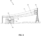
- FIG. 3 illustrates a transmission line configuration of a power flow control system 30 of the present disclosure.
- Wheeled vehicle 10 is shown, on which a set of power flow control subsystems is carried. Each subsystem is in its deployable configuration.
- a jumper cable connection 31 is shown, carried by a pole 32, wherein the connection from the subsystem is made to a phase 33 of a high voltage transmission line, the connection to phase 33 connected through an insulator (not shown) to a transmission line tower 34.
- a shield cable 35 may also be employed as shown.
- In-line transmission separators 36 are also shown. It can be clearly understood that this exemplary configuration of system 30 could be adapted to use the power flow control subsystems connected to a semi-permanent ground pad instead of to a wheeled vehicle.
- FIG. 4 shows a power flow control subsystem 40 in an open frame configuration of the present disclosure, comprising a corona ring 41.
- An exemplary set of six similarly sized modules 42 is shown, each one equipped with a lifting attachment 43, suitable for deployment using a crane for example. Any lifting device may be used, including hydraulic lifters and jackscrew devices.
- At the bottom of power flow control subsystem 40 access tubes (not shown) for lifting with a fork lift may be provided. Straps 44 between modules 42 are also shown; they are electrical bus-bars that transfer voltage and current.
- the open frame configuration is carried on insulating posts 45, with an interface assembly 46 shown for connection to a semi-permanent footing such as 47.
- the semi-permanent footing 47 may be implemented as a concrete pad for example; other types of footings and interface assemblies may also be used.
- An advantage of the open frame configuration of subsystem 40 is that it is easy to maintain, with ready access to the internal modules.
- Figure 5 depicts a power flow control subsystem 50 in a closed frame configuration of the present disclosure, in which a series of doors 51 open to access internal modules (such as a bypass switch module and one or more impedance injection modules) in their deployment configuration.
- closed frame configuration 50 may be more densely constructed, smaller size, lower weight, and less prone to damage during transport and installation.
- a row of cooling fans 52 may be provided as shown.
- Carrying handle 53 is shown, together with corona rings 54. The corona rings 54 assist in reducing arcing to adjacent equipment and to the ground.
- a connector 55 (e.g., national electrical manufacturers association (NEMA) connector) is shown, providing a standard connection method to a phase of a high voltage transmission line supported by a tower for example. This connection may also be made in a substation or any other suitable location, with no tower involved.
- NEMA national electrical manufacturers association
- Figure 6 depicts a set of ground pads 60 at an installation site for a power flow control system.
- the installation site includes semi-permanent footings 61, provided for a semi-permanent installation of power flow control subsystems for example.
- the installation site may include a sufficient number of isolation/insulation posts 62, for installation of several power flow control subsystems.
- Posts 62 may comprise a steel portion for elevating the energized elements to a minimum height above the ground, plus an insulating portion at the top end of each post.
- An exemplary power flow control subsystem includes five impedance injection modules and one bypass switch module in a power flow control subsystem and is operable to perform power flow control of at least 5 MVAR (mega volt amps reactive) (e.g., up to 15 MVAR).
- 5 MVAR mega volt amps reactive
- Figure 7 illustrates a pair of companion wheeled vehicles 71 and 72 for transporting a power flow control system.
- Wheeled vehicles may be transported by road with no additional carrier; they may also be carried as freight by rail, by ship or by air as examples, with road travel to be used near their destination points.
- wheeled vehicle 72 may be called the “guest trailer” or “guest vehicle”; it carries power flow control equipment such as impedance injection module 74 and insulating post 14 and may not be well suited to deployment configurations of power flow control subsystems.
- Wheeled vehicle 71 may be called the "host trailer” or “host vehicle” because the subsystems may be mounted in their deployment configurations, ready for operation in a power flow control system.
- Figure 8 shows a host trailer 71b having three power flow control subsystems 21 mounted in their deployment configuration, ready for power flow operations.
- Guest trailer 72b is empty.
- Host trailer 71b is shown with collapsible outriggers 81, to stabilize the mobile installation.
- Load levelers (not shown) may also be provided.
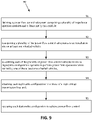
- Figure 9 depicts a flow chart of a method 90 for an exemplary method for installing and operating a power flow control system of the present disclosure.
- Method 90 includes the steps of:
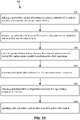
- Figure 10 depicts a flow chart of an alternative exemplary method 100 for installing and operating a power flow control system of the present disclosure.
- Method 100 includes the steps of:
Landscapes
- Engineering & Computer Science (AREA)
- Power Engineering (AREA)
- Manufacturing & Machinery (AREA)
- Supply And Distribution Of Alternating Current (AREA)
Claims (10)
- Untersystem (21, 40, 50) eines Energieflusssteuersystems (30), wobei das Untersystem (21, 40, 50) Folgendes umfasst:eine Vielzahl von Impedanzinjektionsmodulen (13, 42, 73, 74); undmindestens ein Bypassmodul (12, 42);wobei jedes Impedanzinjektionsmodul (13, 42, 73, 74) zum Injizieren einer synthetisierten Wellenform in eine Energieübertragungsleitung ausgelegt ist;wobei die von jedem Impedanzinjektionsmodul (13, 42, 73, 74) injizierte synthetisierte Wellenform eine Kapazität oder eine induktive Impedanz zum Bereitstellen einer Energieflusssteuerung injiziert;wobei das Untersystem (21, 40, 50) in drei Auslegungen auslegbar ist:eine transportierbare Auslegung, in der die Vielzahl von Impedanzinjektionsmodulen (13, 42, 73, 74) und das mindestens eine Bypassmodul (12, 42) dazu ausgelegt sind, an einem Radfahrzeug (10, 20, 71, 71b, 72, 72b) befestigt zu sein und von demselben getragen zu werden;eine implementierbare Auslegung, in der die Vielzahl von Impedanzinjektionsmodulen (13, 42, 73, 74) und das mindestens eine Bypassmodul mechanisch und elektrisch verbunden sind, um eine einzelne Einheit zu bilden, die dazu ausgelegt ist, Energieflussoperationen durchzuführen; undeine Übertragungsleitungsauslegung, in der die implementierbare Auslegung dazu ausgelegt ist, sich zum Ausführen einer Energieflusssteueroperation mit einer Hochspannungsübertragungsleitung zu verbinden;wobei das Untersystem dadurch gekennzeichnet ist, dass:jedes Injektionsimpedanzmodul (13, 42, 73, 74) Spannungs- und Stromsensoren umfasst, die zum Bereitstellen einer frühen Warnung bei einem Fehlerzustand ausgelegt sind, vorzugsweise durch Detektieren eines Stromungleichgewichts von einer Phase zu einer anderen;das mindestens eine Bypassmodul (12) derart ausgelegt ist, dass, wenn in einem Impedanzinjektionsmodul (13, 42, 73, 74) ein Fehlerzustand detektiert wird, das Bypassmodul (12) das Impedanzinjektionsmodul (13, 42, 73, 74) umgeht; unddie implementierbare Auslegung eines von Folgendem umfasst:einen offenen Rahmen mit einem Koronaring (41) peripher zur Vielzahl von Impedanzinjektionsmodulen (13, 42, 73, 74) und zu dem mindestens einen Bypassmodul (12, 42), wobei der Koronaring zum Reduzieren einer Lichtbogenbildung zur benachbarten Ausrüstung und zur Erde ausgelegt ist und wobei die Vielzahl von Impedanzinjektionsmodulen (13, 42, 73, 74) und das mindestens eine Bypassmodul (12, 42) dazu ausgelegt sind, am offenen Rahmen befestigt zu sein; odereinen geschlossenen Rahmen, der eine Vielzahl von Türen (51) und mindestens einen Koronaring (54), der mit dem geschlossenen Rahmen verbunden ist, umfasst, wobei die Vielzahl von Impedanzinjektionsmodulen (13, 73, 74) und das mindestens eine Bypassmodul (12) dazu ausgelegt sind, jeweils im geschlossenen Rahmen enthalten zu sein.
- Untersystem (21, 40, 50) nach Anspruch 1, das ferner dazu ausgelegt ist, eine Energieflusssteuerung auszuführen, während die implementierbare Auslegung vom Radfahrzeug (10, 20, 71, 71b) getragen wird.
- Untersystem (21, 40, 50) nach Anspruch 1, das ferner dazu ausgelegt ist, eine Energieflusssteuerung auszuführen, während die implementierbare Auslegung an einem semipermanenten Fundament befestigt ist.
- Untersystem (21, 40, 50) nach Anspruch 1, wobei jedes der Vielzahl von Impedanzinjektionsmodulen (13, 42, 73, 74) ein transformatorloser statischer Synchronreihenwandler (TSSSC) ist.
- Untersystem (21, 40, 50) nach einem der Ansprüche 1-4, wobei:die Vielzahl von Impedanzinjektionsmodulen (13, 42, 73, 74) fünf Impedanzinjektionsmodule (13, 42, 73, 74) umfasst;das mindestens eine Bypassmodul (12, 42) ein Bypassmodul (12, 42) umfasst; unddas Untersystem (21, 40, 50) dazu ausgelegt ist, eine Energieflusssteuerung von mindestens 5 MVAR (Megavoltampere reaktiv) durchzuführen.
- Untersystem (21, 40, 50) nach einem der vorhergehenden Ansprüche, das ferner dazu ausgelegt ist, mit einem weiteren Untersystem nach einem der vorhergehenden Ansprüche in Reihe verbunden zu sein.
- Verfahren zum Installieren und Betreiben eines Energieflusssteuersystems, das Folgendes umfasst:Definieren eines Energieflusssteueruntersystems (21, 40, 50), das Folgendes umfasst: eine Vielzahl von Impedanzinjektionsmodulen; und mindestens ein Bypassmodul; wobei jedes Impedanzinjektionsmodul zum Injizieren einer synthetisierten Wellenform in eine Energieübertragungsleitung ausgelegt ist; wobei die von jedem Impedanzinjektionsmodul injizierte synthetisierte Wellenform eine Kapazität oder eine induktive Impedanz zum Bereitstellen einer Energieflusssteuerung injiziert; wobei das Untersystem in drei Auslegungen auslegbar ist: eine transportierbare Auslegung, in der die Vielzahl von Impedanzinjektionsmodulen und das mindestens eine Bypassmodul dazu ausgelegt sind, an einem Radfahrzeug befestigt zu sein und von demselben getragen zu werden; eine implementierbare Auslegung, in der die Vielzahl von Impedanzinjektionsmodulen und das mindestens eine Bypassmodul mechanisch und elektrisch verbunden sind, um eine einzelne Einheit zu bilden, die dazu ausgelegt ist, Energieflussoperationen durchzuführen; Und eine Übertragungsleitungsauslegung, in der die implementierbare Auslegung dazu ausgelegt ist, sich zum Ausführen einer Energieflusssteueroperation mit einer Hochspannungsübertragungsleitung zu verbinden; wobei das Untersystem dadurch gekennzeichnet ist, dass: jedes Injektionsimpedanzmodul Spannungs-und Stromsensoren umfasst, die zum Bereitstellen einer frühen Warnung bei einem Fehlerzustand ausgelegt sind, vorzugsweise durch Detektieren eines Stromungleichgewichts von einer Phase zu einer anderen; das mindestens eine Bypassmodul derart ausgelegt ist, dass, wenn in einem Impedanzinjektionsmodul ein Fehlerzustand detektiert wird, das Bypassmodul das Impedanzinjektionsmodul umgeht; und die implementierbare Auslegung eines von Folgendem umfasst: einen offenen Rahmen mit einem Koronaring peripher zur Vielzahl von Impedanzinjektionsmodulen und zu dem mindestens einen Bypassmodul, wobei der Koronaring zum Reduzieren einer Lichtbogenbildung zur benachbarten Ausrüstung und zur Erde ausgelegt ist und wobei die Vielzahl von Impedanzinjektionsmodulen und das mindestens eine Bypassmodul dazu ausgelegt sind, am offenen Rahmen befestigt zu sein; oder einen geschlossenen Rahmen, der eine Vielzahl von Türen und mindestens einen Koronaring, der mit dem geschlossenen Rahmen verbunden ist, umfasst, wobei die Vielzahl von Impedanzinjektionsmodulen und das mindestens eine Bypassmodul dazu ausgelegt sind, jeweils im geschlossenen Rahmen enthalten zu sein;Transportieren einer Vielzahl von Energieflusssteueruntersystemen (21, 40, 50) zu einem Installationsort an mindestens einem Fahrzeug (10, 20, 71, 71b, 72, 72b);Zusammenbauen jedes der Vielzahl von Energieflusssteueruntersystemen (21, 40, 50) zur implementierbaren Auslegung, die betreibbar ist, Energieflussoperationen durchzuführen, wobei entweder:- der Schritt des Zusammenbauens jedes der Vielzahl von Energieflusssteueruntersystemen (21, 40, 50) zur implementierbaren Auslegung, die betreibbar ist, Energieflussoperationen durchzuführen, durchgeführt wird, während das Untersystem (21, 40, 50) von mindestens einem Fahrzeug (10, 20, 71, 71b, 72, 72b) getragen wird; oder- das Verfahren zum Installieren ferner das Montieren von jeder implementierbaren Auslegung auf einem semipermanenten Fundament umfasst;Befestigen von jeder implementierbaren Auslegung an einer Phase einer Hochspannungsübertragungsleitung; und,Betreiben von jeder implementierbaren Auslegung zum Realisieren einer Energieflusssteuerung.
- Verfahren nach Anspruch 7, das ferner das Ausführen einer Energieflusssteueroperation, während die implementierbare Auslegung von dem mindestens einen Fahrzeug (10, 20, 71, 71b) getragen wird oder am semipermanenten Fundament befestigt ist, umfasst.
- Energieflusssteuersystem (30), das Folgendes umfasst:ein Hostradfahrzeug (10, 20, 71, 71b), das zwei Energieflusssteueruntersysteme (21, 40, 50) nach einem der Ansprüche 1 bis 6 umfasst, wobei das Hostradfahrzeug zum Transportieren der Impedanzinjektionsmodule (73) und der Bypassmodule (12) der zwei Energieflusssteueruntersystem (21, 40, 50) ausgelegt ist und wobei das Hostradfahrzeug ferner zum Tragen von zwei Energieflusssteueruntersystem (73) in seiner implementierbaren Auslegung ausgelegt ist;ein Gastradfahrzeug (72, 72b), das ein weiteres Energiesteueruntersystem (21, 40, 50) nach einem der Ansprüche 1 bis 6 umfasst, wobei das Gastradfahrzeug zum Transportieren des weiteren Energiesteueruntersystems (21, 40, 50) ausgelegt ist.
- Energieflusssteuersystem (30) nach Anspruch 9, wobei ein das weitere Energieflusssteueruntersystem (21,40, 50) des Gastradfahrzeugs (72, 72b) dazu ausgelegt ist, am Hostradfahrzeug (10, 20, 71, 71b) in seiner implementierbaren Auslegung montiert zu sein.
Applications Claiming Priority (2)
| Application Number | Priority Date | Filing Date | Title |
|---|---|---|---|
| US201962799630P | 2019-01-31 | 2019-01-31 | |
| US16/590,088 US10938210B2 (en) | 2019-01-31 | 2019-10-01 | Power flow control subsystem having multiple configurations |
Publications (2)
| Publication Number | Publication Date |
|---|---|
| EP3691069A1 EP3691069A1 (de) | 2020-08-05 |
| EP3691069B1 true EP3691069B1 (de) | 2022-09-14 |
Family
ID=69411337
Family Applications (1)
| Application Number | Title | Priority Date | Filing Date |
|---|---|---|---|
| EP20154627.2A Active EP3691069B1 (de) | 2019-01-31 | 2020-01-30 | Subsystem zur leistungsflusssteuerung mit mehreren konfigurationen |
Country Status (4)
| Country | Link |
|---|---|
| US (1) | US10938210B2 (de) |
| EP (1) | EP3691069B1 (de) |
| CN (1) | CN111509698B (de) |
| AU (1) | AU2020200604B2 (de) |
Families Citing this family (7)
| Publication number | Priority date | Publication date | Assignee | Title |
|---|---|---|---|---|
| US20230128146A1 (en) | 2020-03-06 | 2023-04-27 | Boston Scientific Neuromodulation Corporation | Varying Optimal Sub-Perception Stimulation as a Function of Time Using a Modulation Function |
| WO2023028435A1 (en) | 2021-08-24 | 2023-03-02 | Boston Scientific Neuromodulation Corporation | User interface solutions for providing sub-perception stimulation in an implantable stimulator system |
| EP4725399A3 (de) | 2021-12-02 | 2026-06-17 | Boston Scientific Neuromodulation Corporation | Schaltung zur unterstützung der neuralen messung in einer implantierbaren stimulatorvorrichtung bei anwesenheit von stimulationsartefakten |
| WO2023137280A1 (en) | 2022-01-14 | 2023-07-20 | Boston Scientific Neuromodulation Corporation | Algorithm for adjusting a compliance voltage in a stimulator device having neural sensing capability |
| TWI795171B (zh) * | 2022-01-17 | 2023-03-01 | 江鈺堂 | 適用於測試一電纜的測試系統 |
| US20240066303A1 (en) | 2022-08-30 | 2024-02-29 | Boston Scientific Neuromodulation Corporation | Methods and Systems for Determining Baseline Voltages for Sensed Neural Response in an Implantable Stimulator Device System |
| WO2025254971A1 (en) | 2024-06-04 | 2025-12-11 | Boston Scientific Neuromodulation Corporation | Systems and methods for evoked signal sensing using adjustable dc offset compensation |
Family Cites Families (18)
| Publication number | Priority date | Publication date | Assignee | Title |
|---|---|---|---|---|
| US4272740A (en) | 1979-12-13 | 1981-06-09 | Raytheon Company | Coaxial-to-cylindrical array transition |
| US4283685A (en) | 1979-12-13 | 1981-08-11 | Raytheon Company | Waveguide-to-cylindrical array transition |
| US4282492A (en) | 1979-12-13 | 1981-08-04 | Raytheon Company | Modular multiple channel signal processor |
| US4282491A (en) | 1979-12-13 | 1981-08-04 | Raytheon Company | Amplifier with severed transmission lines |
| US4823640A (en) | 1987-10-19 | 1989-04-25 | Donnelly Richard J | Balanced-reaction variable-ratio transmission |
| US7398168B2 (en) | 2005-09-08 | 2008-07-08 | Genscape Intangible Holding, Inc. | Method and system for monitoring power flow through an electric power transmission line |
| WO2010118772A1 (en) | 2009-04-15 | 2010-10-21 | Abb Technology Ag | A converter structure and a modular voltage source converter |
| CN101741094B (zh) * | 2010-01-25 | 2013-02-27 | 株洲变流技术国家工程研究中心有限公司 | 一种基于可关断器件的移动式输电装置 |
| US8512187B2 (en) | 2010-09-15 | 2013-08-20 | Chrysler Group Llc | Multi-mode drive unit |
| DE102012215949A1 (de) | 2012-08-14 | 2014-02-20 | Schaeffler Technologies AG & Co. KG | Riemenscheibenanordnung für einen Riementrieb zum Antrieb von Nebenaggregaten eines Kraftfahrzeugs und Verfahren zum Antrieb eines über eine Riemenscheibenanordnung angebundenen Nebenaggregats eines Kraftfahrzeugs |
| EP2933891B1 (de) | 2014-04-17 | 2022-08-17 | Hitachi Energy Switzerland AG | Lastwiederherstellung in einer Hoch- oder Mittelspannungsunterstation |
| US9399466B2 (en) | 2014-10-13 | 2016-07-26 | Zf Friedrichshafen Ag | Method for operating an automatic transmission |
| CN204967028U (zh) * | 2015-10-19 | 2016-01-13 | 国网山东节能服务有限公司 | 一种集装箱式statcom装置 |
| CN105514905B (zh) * | 2015-12-28 | 2023-08-25 | 中电普瑞科技有限公司 | 一种具有statcom功能的移动式融冰装置 |
| US10193340B2 (en) * | 2017-03-15 | 2019-01-29 | American Superconductor Corporation | Multi-level cascaded H-bridge STATCOM circulating cooling fluid within enclosure |
| KR101950442B1 (ko) | 2017-04-28 | 2019-02-20 | 엘에스산전 주식회사 | 서브모듈 |
| KR101961587B1 (ko) | 2018-01-12 | 2019-03-22 | 이승원 | 제습탈취제 용기 |
| CN108990375B (zh) | 2018-07-23 | 2020-07-28 | 南京南瑞继保电气有限公司 | 一种车载箱式水冷statcom装置 |
-
2019
- 2019-10-01 US US16/590,088 patent/US10938210B2/en active Active
-
2020
- 2020-01-29 AU AU2020200604A patent/AU2020200604B2/en active Active
- 2020-01-30 EP EP20154627.2A patent/EP3691069B1/de active Active
- 2020-02-03 CN CN202010078931.9A patent/CN111509698B/zh active Active
Also Published As
| Publication number | Publication date |
|---|---|
| US10938210B2 (en) | 2021-03-02 |
| CN111509698B (zh) | 2025-12-19 |
| AU2020200604B2 (en) | 2025-04-03 |
| CN111509698A (zh) | 2020-08-07 |
| EP3691069A1 (de) | 2020-08-05 |
| US20200251899A1 (en) | 2020-08-06 |
| AU2020200604A1 (en) | 2020-08-20 |
Similar Documents
| Publication | Publication Date | Title |
|---|---|---|
| AU2020200604B2 (en) | Power flow control subsystem having multiple configurations | |
| JP2021510290A (ja) | 洋上ウィンドファームおよびサブステーション | |
| CN102684087B (zh) | 不停电更换配电变压器的旁路作业车 | |
| JP4966246B2 (ja) | 移動用ガス絶縁開閉装置及びその現地運用方法 | |
| US11807149B2 (en) | Deployment of power flow control systems | |
| CN110676739A (zh) | 一种移动式变电站 | |
| US11050357B2 (en) | Modular multilevel power converter in which electronic components of the converter are arranged on different vehicles | |
| CN211266433U (zh) | 一种高压电缆分接装置 | |
| AU2023377461B2 (en) | Process and system for pole and conductor installation for charging while moving | |
| CN112379305A (zh) | 一种牵引变流器的接地检测电路及其控制方法 | |
| US12438344B2 (en) | Scalable and portable AC/DC substation | |
| WO2024108235A9 (en) | Modular, expandable, prefabricated chassis for electrical vehicle charging stations | |
| EP2859630B1 (de) | Bypass-system für freileitungen | |
| CN211351468U (zh) | 一种车载可移动式gis设备 | |
| US20020001170A1 (en) | System for assembly and maintenance of connection modules in high- voltage switchgear, a method therefor and a system component | |
| CN111049054B (zh) | 一种车载可移动式gis设备 | |
| CN203415864U (zh) | 一种新型移动式电源装置 | |
| CN208508535U (zh) | 一体式紧凑型高压并联电抗器成套装置 | |
| CN106786260A (zh) | 一种移动式可拆卸翻盖式配电箱 | |
| CN112698166A (zh) | 组合式一体化试验装置 | |
| CN217444212U (zh) | 一种有效降低容性电流的电感器 | |
| CN202663116U (zh) | 车载调容高电压电力电容器装置 | |
| CN214044891U (zh) | 一种矿用挖掘机高压电缆接线箱 | |
| CN201084549Y (zh) | 一种用于电容器保护和安全放电的装置 | |
| WO2026050868A1 (en) | A support assembly for a mining site |
Legal Events
| Date | Code | Title | Description |
|---|---|---|---|
| PUAI | Public reference made under article 153(3) epc to a published international application that has entered the european phase |
Free format text: ORIGINAL CODE: 0009012 |
|
| STAA | Information on the status of an ep patent application or granted ep patent |
Free format text: STATUS: THE APPLICATION HAS BEEN PUBLISHED |
|
| AK | Designated contracting states |
Kind code of ref document: A1 Designated state(s): AL AT BE BG CH CY CZ DE DK EE ES FI FR GB GR HR HU IE IS IT LI LT LU LV MC MK MT NL NO PL PT RO RS SE SI SK SM TR |
|
| AX | Request for extension of the european patent |
Extension state: BA ME |
|
| STAA | Information on the status of an ep patent application or granted ep patent |
Free format text: STATUS: REQUEST FOR EXAMINATION WAS MADE |
|
| 17P | Request for examination filed |
Effective date: 20210204 |
|
| RBV | Designated contracting states (corrected) |
Designated state(s): AL AT BE BG CH CY CZ DE DK EE ES FI FR GB GR HR HU IE IS IT LI LT LU LV MC MK MT NL NO PL PT RO RS SE SI SK SM TR |
|
| RIN1 | Information on inventor provided before grant (corrected) |
Inventor name: BLOCH-RUBIN, TED Inventor name: HEIER, CASEY Inventor name: SCHMAUTZ, WILL Inventor name: PUCHTA, BRYCE Inventor name: SANDERS, MARK Inventor name: FARAHANI, ALI Inventor name: PARKS, JOHN |
|
| STAA | Information on the status of an ep patent application or granted ep patent |
Free format text: STATUS: EXAMINATION IS IN PROGRESS |
|
| 17Q | First examination report despatched |
Effective date: 20210721 |
|
| GRAP | Despatch of communication of intention to grant a patent |
Free format text: ORIGINAL CODE: EPIDOSNIGR1 |
|
| STAA | Information on the status of an ep patent application or granted ep patent |
Free format text: STATUS: GRANT OF PATENT IS INTENDED |
|
| INTG | Intention to grant announced |
Effective date: 20220617 |
|
| GRAS | Grant fee paid |
Free format text: ORIGINAL CODE: EPIDOSNIGR3 |
|
| GRAA | (expected) grant |
Free format text: ORIGINAL CODE: 0009210 |
|
| STAA | Information on the status of an ep patent application or granted ep patent |
Free format text: STATUS: THE PATENT HAS BEEN GRANTED |
|
| AK | Designated contracting states |
Kind code of ref document: B1 Designated state(s): AL AT BE BG CH CY CZ DE DK EE ES FI FR GB GR HR HU IE IS IT LI LT LU LV MC MK MT NL NO PL PT RO RS SE SI SK SM TR |
|
| REG | Reference to a national code |
Ref country code: GB Ref legal event code: FG4D |
|
| REG | Reference to a national code |
Ref country code: CH Ref legal event code: EP |
|
| REG | Reference to a national code |
Ref country code: DE Ref legal event code: R096 Ref document number: 602020005045 Country of ref document: DE |
|
| REG | Reference to a national code |
Ref country code: IE Ref legal event code: FG4D |
|
| REG | Reference to a national code |
Ref country code: AT Ref legal event code: REF Ref document number: 1519285 Country of ref document: AT Kind code of ref document: T Effective date: 20221015 |
|
| REG | Reference to a national code |
Ref country code: LT Ref legal event code: MG9D |
|
| REG | Reference to a national code |
Ref country code: NL Ref legal event code: MP Effective date: 20220914 |
|
| PG25 | Lapsed in a contracting state [announced via postgrant information from national office to epo] |
Ref country code: SE Free format text: LAPSE BECAUSE OF FAILURE TO SUBMIT A TRANSLATION OF THE DESCRIPTION OR TO PAY THE FEE WITHIN THE PRESCRIBED TIME-LIMIT Effective date: 20220914 Ref country code: RS Free format text: LAPSE BECAUSE OF FAILURE TO SUBMIT A TRANSLATION OF THE DESCRIPTION OR TO PAY THE FEE WITHIN THE PRESCRIBED TIME-LIMIT Effective date: 20220914 Ref country code: NO Free format text: LAPSE BECAUSE OF FAILURE TO SUBMIT A TRANSLATION OF THE DESCRIPTION OR TO PAY THE FEE WITHIN THE PRESCRIBED TIME-LIMIT Effective date: 20221214 Ref country code: LV Free format text: LAPSE BECAUSE OF FAILURE TO SUBMIT A TRANSLATION OF THE DESCRIPTION OR TO PAY THE FEE WITHIN THE PRESCRIBED TIME-LIMIT Effective date: 20220914 Ref country code: LT Free format text: LAPSE BECAUSE OF FAILURE TO SUBMIT A TRANSLATION OF THE DESCRIPTION OR TO PAY THE FEE WITHIN THE PRESCRIBED TIME-LIMIT Effective date: 20220914 Ref country code: FI Free format text: LAPSE BECAUSE OF FAILURE TO SUBMIT A TRANSLATION OF THE DESCRIPTION OR TO PAY THE FEE WITHIN THE PRESCRIBED TIME-LIMIT Effective date: 20220914 |
|
| REG | Reference to a national code |
Ref country code: AT Ref legal event code: MK05 Ref document number: 1519285 Country of ref document: AT Kind code of ref document: T Effective date: 20220914 |
|
| PG25 | Lapsed in a contracting state [announced via postgrant information from national office to epo] |
Ref country code: HR Free format text: LAPSE BECAUSE OF FAILURE TO SUBMIT A TRANSLATION OF THE DESCRIPTION OR TO PAY THE FEE WITHIN THE PRESCRIBED TIME-LIMIT Effective date: 20220914 Ref country code: GR Free format text: LAPSE BECAUSE OF FAILURE TO SUBMIT A TRANSLATION OF THE DESCRIPTION OR TO PAY THE FEE WITHIN THE PRESCRIBED TIME-LIMIT Effective date: 20221215 |
|
| PG25 | Lapsed in a contracting state [announced via postgrant information from national office to epo] |
Ref country code: SM Free format text: LAPSE BECAUSE OF FAILURE TO SUBMIT A TRANSLATION OF THE DESCRIPTION OR TO PAY THE FEE WITHIN THE PRESCRIBED TIME-LIMIT Effective date: 20220914 Ref country code: RO Free format text: LAPSE BECAUSE OF FAILURE TO SUBMIT A TRANSLATION OF THE DESCRIPTION OR TO PAY THE FEE WITHIN THE PRESCRIBED TIME-LIMIT Effective date: 20220914 Ref country code: PT Free format text: LAPSE BECAUSE OF FAILURE TO SUBMIT A TRANSLATION OF THE DESCRIPTION OR TO PAY THE FEE WITHIN THE PRESCRIBED TIME-LIMIT Effective date: 20230116 Ref country code: ES Free format text: LAPSE BECAUSE OF FAILURE TO SUBMIT A TRANSLATION OF THE DESCRIPTION OR TO PAY THE FEE WITHIN THE PRESCRIBED TIME-LIMIT Effective date: 20220914 Ref country code: CZ Free format text: LAPSE BECAUSE OF FAILURE TO SUBMIT A TRANSLATION OF THE DESCRIPTION OR TO PAY THE FEE WITHIN THE PRESCRIBED TIME-LIMIT Effective date: 20220914 Ref country code: AT Free format text: LAPSE BECAUSE OF FAILURE TO SUBMIT A TRANSLATION OF THE DESCRIPTION OR TO PAY THE FEE WITHIN THE PRESCRIBED TIME-LIMIT Effective date: 20220914 |
|
| PG25 | Lapsed in a contracting state [announced via postgrant information from national office to epo] |
Ref country code: SK Free format text: LAPSE BECAUSE OF FAILURE TO SUBMIT A TRANSLATION OF THE DESCRIPTION OR TO PAY THE FEE WITHIN THE PRESCRIBED TIME-LIMIT Effective date: 20220914 Ref country code: PL Free format text: LAPSE BECAUSE OF FAILURE TO SUBMIT A TRANSLATION OF THE DESCRIPTION OR TO PAY THE FEE WITHIN THE PRESCRIBED TIME-LIMIT Effective date: 20220914 Ref country code: IS Free format text: LAPSE BECAUSE OF FAILURE TO SUBMIT A TRANSLATION OF THE DESCRIPTION OR TO PAY THE FEE WITHIN THE PRESCRIBED TIME-LIMIT Effective date: 20230114 Ref country code: EE Free format text: LAPSE BECAUSE OF FAILURE TO SUBMIT A TRANSLATION OF THE DESCRIPTION OR TO PAY THE FEE WITHIN THE PRESCRIBED TIME-LIMIT Effective date: 20220914 |
|
| REG | Reference to a national code |
Ref country code: DE Ref legal event code: R097 Ref document number: 602020005045 Country of ref document: DE |
|
| PG25 | Lapsed in a contracting state [announced via postgrant information from national office to epo] |
Ref country code: NL Free format text: LAPSE BECAUSE OF FAILURE TO SUBMIT A TRANSLATION OF THE DESCRIPTION OR TO PAY THE FEE WITHIN THE PRESCRIBED TIME-LIMIT Effective date: 20220914 Ref country code: AL Free format text: LAPSE BECAUSE OF FAILURE TO SUBMIT A TRANSLATION OF THE DESCRIPTION OR TO PAY THE FEE WITHIN THE PRESCRIBED TIME-LIMIT Effective date: 20220914 |
|
| PLBE | No opposition filed within time limit |
Free format text: ORIGINAL CODE: 0009261 |
|
| STAA | Information on the status of an ep patent application or granted ep patent |
Free format text: STATUS: NO OPPOSITION FILED WITHIN TIME LIMIT |
|
| PG25 | Lapsed in a contracting state [announced via postgrant information from national office to epo] |
Ref country code: DK Free format text: LAPSE BECAUSE OF FAILURE TO SUBMIT A TRANSLATION OF THE DESCRIPTION OR TO PAY THE FEE WITHIN THE PRESCRIBED TIME-LIMIT Effective date: 20220914 |
|
| 26N | No opposition filed |
Effective date: 20230615 |
|
| PG25 | Lapsed in a contracting state [announced via postgrant information from national office to epo] |
Ref country code: SI Free format text: LAPSE BECAUSE OF FAILURE TO SUBMIT A TRANSLATION OF THE DESCRIPTION OR TO PAY THE FEE WITHIN THE PRESCRIBED TIME-LIMIT Effective date: 20220914 |
|
| REG | Reference to a national code |
Ref country code: CH Ref legal event code: PL |
|
| PG25 | Lapsed in a contracting state [announced via postgrant information from national office to epo] |
Ref country code: LU Free format text: LAPSE BECAUSE OF NON-PAYMENT OF DUE FEES Effective date: 20230130 |
|
| REG | Reference to a national code |
Ref country code: BE Ref legal event code: MM Effective date: 20230131 |
|
| PG25 | Lapsed in a contracting state [announced via postgrant information from national office to epo] |
Ref country code: LI Free format text: LAPSE BECAUSE OF NON-PAYMENT OF DUE FEES Effective date: 20230131 Ref country code: CH Free format text: LAPSE BECAUSE OF NON-PAYMENT OF DUE FEES Effective date: 20230131 |
|
| PG25 | Lapsed in a contracting state [announced via postgrant information from national office to epo] |
Ref country code: FR Free format text: LAPSE BECAUSE OF NON-PAYMENT OF DUE FEES Effective date: 20230131 Ref country code: BE Free format text: LAPSE BECAUSE OF NON-PAYMENT OF DUE FEES Effective date: 20230131 |
|
| PG25 | Lapsed in a contracting state [announced via postgrant information from national office to epo] |
Ref country code: IE Free format text: LAPSE BECAUSE OF NON-PAYMENT OF DUE FEES Effective date: 20230130 |
|
| PG25 | Lapsed in a contracting state [announced via postgrant information from national office to epo] |
Ref country code: IT Free format text: LAPSE BECAUSE OF FAILURE TO SUBMIT A TRANSLATION OF THE DESCRIPTION OR TO PAY THE FEE WITHIN THE PRESCRIBED TIME-LIMIT Effective date: 20220914 |
|
| PG25 | Lapsed in a contracting state [announced via postgrant information from national office to epo] |
Ref country code: MC Free format text: LAPSE BECAUSE OF FAILURE TO SUBMIT A TRANSLATION OF THE DESCRIPTION OR TO PAY THE FEE WITHIN THE PRESCRIBED TIME-LIMIT Effective date: 20220914 |
|
| PG25 | Lapsed in a contracting state [announced via postgrant information from national office to epo] |
Ref country code: MC Free format text: LAPSE BECAUSE OF FAILURE TO SUBMIT A TRANSLATION OF THE DESCRIPTION OR TO PAY THE FEE WITHIN THE PRESCRIBED TIME-LIMIT Effective date: 20220914 |
|
| PG25 | Lapsed in a contracting state [announced via postgrant information from national office to epo] |
Ref country code: BG Free format text: LAPSE BECAUSE OF FAILURE TO SUBMIT A TRANSLATION OF THE DESCRIPTION OR TO PAY THE FEE WITHIN THE PRESCRIBED TIME-LIMIT Effective date: 20220914 |
|
| PG25 | Lapsed in a contracting state [announced via postgrant information from national office to epo] |
Ref country code: BG Free format text: LAPSE BECAUSE OF FAILURE TO SUBMIT A TRANSLATION OF THE DESCRIPTION OR TO PAY THE FEE WITHIN THE PRESCRIBED TIME-LIMIT Effective date: 20220914 |
|
| PG25 | Lapsed in a contracting state [announced via postgrant information from national office to epo] |
Ref country code: CY Free format text: LAPSE BECAUSE OF FAILURE TO SUBMIT A TRANSLATION OF THE DESCRIPTION OR TO PAY THE FEE WITHIN THE PRESCRIBED TIME-LIMIT; INVALID AB INITIO Effective date: 20200130 |
|
| PG25 | Lapsed in a contracting state [announced via postgrant information from national office to epo] |
Ref country code: HU Free format text: LAPSE BECAUSE OF FAILURE TO SUBMIT A TRANSLATION OF THE DESCRIPTION OR TO PAY THE FEE WITHIN THE PRESCRIBED TIME-LIMIT; INVALID AB INITIO Effective date: 20200130 |
|
| PG25 | Lapsed in a contracting state [announced via postgrant information from national office to epo] |
Ref country code: TR Free format text: LAPSE BECAUSE OF FAILURE TO SUBMIT A TRANSLATION OF THE DESCRIPTION OR TO PAY THE FEE WITHIN THE PRESCRIBED TIME-LIMIT Effective date: 20220914 |
|
| PGFP | Annual fee paid to national office [announced via postgrant information from national office to epo] |
Ref country code: GB Payment date: 20260123 Year of fee payment: 7 |
|
| PGFP | Annual fee paid to national office [announced via postgrant information from national office to epo] |
Ref country code: DE Payment date: 20260121 Year of fee payment: 7 |