EP3690483A1 - A method for synthesis of antenna array layouts or selection of waveform in a set of mutually incoherent apertures for radar and radio-frequency applications - Google Patents
A method for synthesis of antenna array layouts or selection of waveform in a set of mutually incoherent apertures for radar and radio-frequency applications Download PDFInfo
- Publication number
- EP3690483A1 EP3690483A1 EP19155199.3A EP19155199A EP3690483A1 EP 3690483 A1 EP3690483 A1 EP 3690483A1 EP 19155199 A EP19155199 A EP 19155199A EP 3690483 A1 EP3690483 A1 EP 3690483A1
- Authority
- EP
- European Patent Office
- Prior art keywords
- apertures
- aperture
- radar
- optimization
- incoherent
- Prior art date
- Legal status (The legal status is an assumption and is not a legal conclusion. Google has not performed a legal analysis and makes no representation as to the accuracy of the status listed.)
- Granted
Links
Images


Classifications
-
- G—PHYSICS
- G01—MEASURING; TESTING
- G01S—RADIO DIRECTION-FINDING; RADIO NAVIGATION; DETERMINING DISTANCE OR VELOCITY BY USE OF RADIO WAVES; LOCATING OR PRESENCE-DETECTING BY USE OF THE REFLECTION OR RERADIATION OF RADIO WAVES; ANALOGOUS ARRANGEMENTS USING OTHER WAVES
- G01S13/00—Systems using the reflection or reradiation of radio waves, e.g. radar systems; Analogous systems using reflection or reradiation of waves whose nature or wavelength is irrelevant or unspecified
- G01S13/88—Radar or analogous systems specially adapted for specific applications
-
- G—PHYSICS
- G01—MEASURING; TESTING
- G01S—RADIO DIRECTION-FINDING; RADIO NAVIGATION; DETERMINING DISTANCE OR VELOCITY BY USE OF RADIO WAVES; LOCATING OR PRESENCE-DETECTING BY USE OF THE REFLECTION OR RERADIATION OF RADIO WAVES; ANALOGOUS ARRANGEMENTS USING OTHER WAVES
- G01S13/00—Systems using the reflection or reradiation of radio waves, e.g. radar systems; Analogous systems using reflection or reradiation of waves whose nature or wavelength is irrelevant or unspecified
- G01S13/003—Bistatic radar systems; Multistatic radar systems
-
- G—PHYSICS
- G01—MEASURING; TESTING
- G01S—RADIO DIRECTION-FINDING; RADIO NAVIGATION; DETERMINING DISTANCE OR VELOCITY BY USE OF RADIO WAVES; LOCATING OR PRESENCE-DETECTING BY USE OF THE REFLECTION OR RERADIATION OF RADIO WAVES; ANALOGOUS ARRANGEMENTS USING OTHER WAVES
- G01S13/00—Systems using the reflection or reradiation of radio waves, e.g. radar systems; Analogous systems using reflection or reradiation of waves whose nature or wavelength is irrelevant or unspecified
- G01S13/02—Systems using reflection of radio waves, e.g. primary radar systems; Analogous systems
- G01S13/06—Systems determining position data of a target
- G01S13/42—Simultaneous measurement of distance and other co-ordinates
-
- G—PHYSICS
- G01—MEASURING; TESTING
- G01S—RADIO DIRECTION-FINDING; RADIO NAVIGATION; DETERMINING DISTANCE OR VELOCITY BY USE OF RADIO WAVES; LOCATING OR PRESENCE-DETECTING BY USE OF THE REFLECTION OR RERADIATION OF RADIO WAVES; ANALOGOUS ARRANGEMENTS USING OTHER WAVES
- G01S7/00—Details of systems according to groups G01S13/00, G01S15/00, G01S17/00
- G01S7/02—Details of systems according to groups G01S13/00, G01S15/00, G01S17/00 of systems according to group G01S13/00
- G01S7/28—Details of pulse systems
- G01S7/282—Transmitters
-
- G—PHYSICS
- G01—MEASURING; TESTING
- G01S—RADIO DIRECTION-FINDING; RADIO NAVIGATION; DETERMINING DISTANCE OR VELOCITY BY USE OF RADIO WAVES; LOCATING OR PRESENCE-DETECTING BY USE OF THE REFLECTION OR RERADIATION OF RADIO WAVES; ANALOGOUS ARRANGEMENTS USING OTHER WAVES
- G01S7/00—Details of systems according to groups G01S13/00, G01S15/00, G01S17/00
- G01S7/02—Details of systems according to groups G01S13/00, G01S15/00, G01S17/00 of systems according to group G01S13/00
- G01S7/35—Details of non-pulse systems
-
- G—PHYSICS
- G01—MEASURING; TESTING
- G01S—RADIO DIRECTION-FINDING; RADIO NAVIGATION; DETERMINING DISTANCE OR VELOCITY BY USE OF RADIO WAVES; LOCATING OR PRESENCE-DETECTING BY USE OF THE REFLECTION OR RERADIATION OF RADIO WAVES; ANALOGOUS ARRANGEMENTS USING OTHER WAVES
- G01S13/00—Systems using the reflection or reradiation of radio waves, e.g. radar systems; Analogous systems using reflection or reradiation of waves whose nature or wavelength is irrelevant or unspecified
- G01S13/88—Radar or analogous systems specially adapted for specific applications
- G01S13/885—Radar or analogous systems specially adapted for specific applications for ground probing
-
- G—PHYSICS
- G01—MEASURING; TESTING
- G01S—RADIO DIRECTION-FINDING; RADIO NAVIGATION; DETERMINING DISTANCE OR VELOCITY BY USE OF RADIO WAVES; LOCATING OR PRESENCE-DETECTING BY USE OF THE REFLECTION OR RERADIATION OF RADIO WAVES; ANALOGOUS ARRANGEMENTS USING OTHER WAVES
- G01S13/00—Systems using the reflection or reradiation of radio waves, e.g. radar systems; Analogous systems using reflection or reradiation of waves whose nature or wavelength is irrelevant or unspecified
- G01S13/88—Radar or analogous systems specially adapted for specific applications
- G01S13/93—Radar or analogous systems specially adapted for specific applications for anti-collision purposes
- G01S13/931—Radar or analogous systems specially adapted for specific applications for anti-collision purposes of land vehicles
Definitions
- the present invention relates to the design of optimal antenna arrays for radar and radio-frequency applications comprised of mutually incoherent apertures that enable high angular resolution and localization estimation with unpreceded flexibility in usage of available space, and without need to synchronize widely separated transmit and/or receive antenna elements, avoiding the phase errors associated to lack of synchrony, deformations, and vibrations, and making unnecessary techniques such as auto-focusing or blind calibration between apertures that would require several snapshots, while maintaining a combined effective array factor with low sidelobes, all these characteristics suitable for applications to automotive radar for advance driver assistance systems (ADAS), ground-penetrating radar, synthetic aperture radar, medical imaging, navigation systems, and communications.
- ADAS advance driver assistance systems
- the present invention also relates to a method for selection of waveform in a set of mutually incoherent apertures for radar and radio-frequency applications.
- High-resolution direction of arrival (DoA) estimation has crucial importance in most radar and communication systems.
- functions such as lane change assist and collision avoidance systems require high angular resolution in both forward and rear-facing radars to discern the lane of other vehicles and obstacles at long distances, especially at high speeds, cf. Fig. 1 .
- the necessary aperture size and number of transmit and receive elements increase the required space and complexity of the hardware to achieve synchronization, particularly at high frequencies, which poses a challenge on the overall design and raises the cost.
- the disclosed invention presents a design method for synthesis of antenna element positions of mutually incoherent apertures, which relaxes the constraints on required physical space and synchronization associated to prior art on design of coherent apertures, while ensuring a satisfactory performance of angular estimation.
- PRELIMINARIES MODEL FOR RADIATION PATTERN (Prior-Art)
- the physical model used in prior art for optimization of antenna element positions considers a geometric arrangement of antenna elements that by coherent transmission produces a so-called radiation or beam-pattern, referring to the power directionality when certain complex amplitudes are applied to the radiating antennas through a beam-former network.
- this model also represents the estimation method of beamforming or Delay-and-Sum wherein the powered received in any hypothetical direction is quantified for a given direction of the emitting or reflecting object.
- Fig. 2 shows the model of planar wave fronts for azimuth and elevation angle with respect
- the ambiguity between a hypothesis ⁇ ' and the signal's true parameter ⁇ is produced by a high value of AF ( ⁇ , ⁇ ' ).
- ⁇ min ⁇ max ⁇ R q is the rectangular domain, or field-of-view, with entry-wise lower and upper bounds.
- ⁇ . ⁇ p is the p-norm, for suitable p ⁇ [1, ⁇ ]
- the function c ⁇ c ( ⁇ ) > 0 is the caliber, which is a design parameter commonly used [2] [3] [4] (and normally taken as constant) to set a limit for the mainlobe width (MLW), such that outside of the 2 q -dimensional band, the peaks of AF ( ⁇ , ⁇ ' ) are quantified as sidelobes.
- MLW mainlobe width
- S ⁇ R 3 ⁇ M represents the domain for the antenna positions, including spatial and minimum separation constraints to avoid electromagnetic coupling.
- in (1) by selecting b [ b 1 , ⁇ , b M ] equal to a FF ( u' ) . That is, the radiation pattern, i.e., the power received at spatial frequency or direction u when the beam is steered at direction u' , coincides with the ambiguity function AF ( u,u' ) .
- the array factor can be expressed as a product in terms of antenna positions, which allows to create nulls at desired angles and control the sidelobe level, and for circular ring arrays, EP2949002A1 (see also WO2014114993A1 ), it is possible to derive some optimality conditions for the rings' radii.
- the far-field model has the advantage of fast processing using the Fast Fourier Transform (FFT) and other beamformers like MUSIC and ESPRIT.
- FFT Fast Fourier Transform
- MUSIC MUSIC
- ESPRIT angular variables
- using the far-field is not incompatible with using the angular variables ⁇ , ⁇ instead of the spatial frequencies [ u , v,w ] to parametrize the array factor.
- the design of the arrays can be performed using the parametrization in terms of [ ⁇ , ⁇ ], even if it fails to satisfy the symmetry relation in (13) which in any case is unnecessary for (5).
- the degrees of freedom for the optimization are the Tx and Rx antenna positions.
- the near-field model for DoA estimation is a more realistic in some applications like medical imaging and also for automotive radar using arrays of certain aperture.
- This model concerns the path of the signals from transmitters to object and back to receivers.
- the corresponding near-field steering vector for transmission a Tx NF n ⁇ r is defined similarly.
- the dependency of the near-field virtual steering vector on antenna positions is not through the virtual array in (15). Nonetheless, we can still refer to such coherent sets of Tx and Rx elements as a virtual aperture, which will be convenient when we define multiple such mutually incoherent apertures.
- the range r is a parameter that has a different treatment depending on the application and for design purposes it can be assumed in a certain interval.
- Analogous models include (a) DoA estimation under the far-field model using the electronic angles, and (b) Doppler estimation, where instead of having dependence on the antenna locations, there is a dependence on the carrier frequency and on the pulse repetition interval or non-uniform transmission times of the pulses.
- Another equivalent model is range estimation using a waveform with time-multiplexed or simultaneous frequencies, illustrated next. This waveform finds applications in ground penetrating radar [12], and SFCW for automotive radar [13] [14]. For simplicity, consider a transmitter and a receiver at the same location.
- k M c max ⁇ r ⁇ c , r max ⁇ r min AF PC ⁇ r , where the caliber c > 0 can be chosen according to a desired resolution. It is common in radar and radio-frequency applications to refer to the coherent sampling domain, being the antenna array layout (spatial domain), or available bandwidth (frequency domain), as available aperture. We will use this notation also to refer to sets of apertures that are mutually incoherent, spatially or in frequency.
- PRELIMINARIES OTHER OPTIMIZATION METRICS FOR COHERENT APERTURES (Prior-Art)
- BCRB Bayesian Cramer-Rao Bound
- WWB Weiss-Weinstein Bound
- ZZB Ziv-Zakai bound
- Model (2) concerns a single coherent aperture because the signals of the different antennas are combined with known phases.
- the literature on array design considers the optimization of antenna element positions only in said case of coherent apertures [2] [3] [4].
- Work [21] was the first to consider this problem, and more recently the available computational power has popularized nonlinear global optimization methods such as genetic algorithms, particle swarm optimization, and simulated annealing [22].
- the optimization has also been performed for non-planar arrays, including conformal arrays [8].
- prior patent applications again only the case of coherent arrays is studied, as we outline next with some exemplary works.
- US3877033A describes a synthesis method of non-uniform arrays with uniform amplitudes (following the seminal work by the author in [21]) with a much lower sidelobe-level of the radiation pattern than the uniform counterparts, based on a factorization of the array factor, normally given by a sum of cosines for symmetric arrays, in terms of a multiplication of cosines in terms of the element positions, which yields a sequential and computationally fast method for optimal placement of an arbitrary number of antenna elements.
- WO2009140998A1 describes a method for thinning a given array (i.e., removing elements from an initially uniform array) using as optimization metric a combination of the angular estimation performance and the sidelobe level.
- the former is quantified in terms of the MSE or a lower bound thereof such as the CRB.
- EP2949002A1 (see also WO2014114993A1 ) describes a method for joint optimization of element positions and dimensions for planar sparse arrays, especially circular ring arrays.
- the optimization method makes some assumptions about the structure of the array to employ certain analytic optimality conditions.
- CN105426578B presents an optimization method for planar arrays for MIMO Synthetic Aperture Radar. The optimization of SLL and MLW is performed using genetic algorithms.
- the digital signal processing can optionally include match-filtering for range-Doppler processing or, typically in automotive radar, 2D-FFT.
- the following signal model can include spatiotemporal sampling and is not restricted to angle estimation, thus broadening the applicability of the disclosed invention for design of optimal non-uniform sampling and illumination with stepped frequencies under incoherency.
- the measurements are grouped for each coherent aperture, and can refer to time, frequency, or spatial samples.
- each virtual aperture l ⁇ ⁇ 1,..., L ⁇ is defined as follows.
- the noise after previous filtering is denoted by w l ⁇ C m l and its distribution does not play a role unless explicitly mentioned in embodiment 3 where we introduce the likelihood under Gaussian models. That is, we consider the deterministic ambiguity function associated to the geometry of the samples.
- the signal models for each of the blocks, a l ⁇ k ⁇ C m l are expressed in a common-reference frame, and can correspond to angle of arrival estimation under far-field or near-field models for narrow-band sources, Doppler estimation with non-uniform pulse repetition intervals [23], and range estimation [23] [11].
- [15] presents a radar system architecture based on Compressed Sensing for high range resolution [30], and ISAR, where only specific frequencies are generated, thus using the spectrum more efficiently and reducing the rate of sampling data.
- [31] explains a method for measurement acquisition and delay estimation based on Doppler focusing for increasing SNR and guaranteeing sparsity in fast-time domain (i.e., range domain).
- This work estimates the delay using Compressed Sensing with a set of Fourier coefficients, which can be obtained via direct sampling [32], or sampling different spectral bands using a sub-Nyquist measurement-acquisition process denominated Xampling, and then matching the Fourier coefficients digitally [33].
- Other design techniques for sub-sampling a signal include multicoset sampling [34], which is amenable to CS techniques [35]. This model has been used for the optimization of spatially variant apodization (tapering) assuming coherency [36].
- US9448302B2 (Method for operating a MIMO radar), related to [39] [40], presents a time-multiplexed schema where transmission instants are optimized according to a mathematical expression based on the Cramer-Rao Bound for joint estimation of DoA and Doppler assuming a coherent group of antennas. This accomplishes a reduction of the effect of movement and consequent Doppler frequency shift on DoA estimation accuracy when all the antennas of a MIMO system are used with time-domain multiplexing.
- a synthesis of antenna array layouts is described based on mutually incoherent apertures in terms of an optimization problem for given constraints on the number of mutually incoherent apertures, the total number of Tx and Rx elements, the maximum size of each aperture, and the field-of-view.
- Other design hyper-parameters for near-field models may include the set of ranges over which the metric is averaged.
- the design method includes the provision of a metric with ambiguity functions formulated for Block Orthogonal Matching Pursuit (BOMP), Tropp's Exact Recovery Condition (ERC), and Maximum Likelihood, for a signal model that includes random initial phases between apertures, and the selection of transmit and receive antenna locations according to said metric based on optimization of the corresponding ambiguity functions.
- the optimization is performed such that a sidelobe level (and/or features dependent on the sidelobe level) associated to said ambiguity functions over a number of dimensions corresponding to one or several parameters of interest, including azimuth and/or elevation, is minimized.
- the proposed method for selection of waveform accordingly includes the provision of a metric with ambiguity functions based on a signal model that includes random initial phases between apertures, and the selection of frequencies and/or pulse transmission times according to said metric based on optimization of the ambiguity functions such that a sidelobe level (and/or features dependent on the sidelobe level) associated to said ambiguity functions over a number of dimensions corresponding to one or several parameters of interest, including range and/or Doppler, is minimized.
- the principle of the invention for design of array layouts of mutually incoherent apertures is the following.
- group-sparse reconstruction algorithms and other beamformers exhibit an improved estimation performance because the design method allows to optimize the resolution of the mutually incoherent apertures by using more effectively the available space without the need to keep a low sidelobe level in each individual aperture thanks to the mutual cancellation of sidelobes.
- the proposed method and exemplary array layouts are particularly suited, given the above benefits, for design of a constellation of incoherent apertures for automotive radar, optimized for short, medium and long range functionalities and possibly with full 360° coverage to enable at low cost all advance driving assistant systems, from lane change assist, to collision warning and emergency braking. Nonetheless, it can also find applications in airborne and satellite radar, synthetic aperture radar, remote sensing, communications, and navigation systems.
- PRELIMINARIES GROUP-SPARSE RECONSTRUCTION FOR INCOHERENT APERTURES (Prior-Art)
- the estimation of the parameter vectors ⁇ 1 ⁇ 2 ... ⁇ K ⁇ R q for each of the K targets for the general signal model (19) can be formulated as a group-sparse reconstruction problem, which entails fitting the measurements of each virtual aperture by a sparse linear super-position of single-source predictions selected from an over-complete dictionary of hypotheses.
- the quantity x ⁇ ⁇ R N can be interpreted as the amplitude map for the parameter of interest over the N -grid.
- the measurement fidelity constraints (20) do not couple the phase differences between mutually incoherent virtual apertures because these are assumed arbitrary due to lack of synchronization, vibrations, etc.
- BOMP group-sparse reconstruction algorithms analog to ones for standard sparsity.
- BOMP has the following strategy for group selection (or block of atoms) in the case of incoherent sensors [27].
- steps (22) and (23) are the only ones that combine information among apertures and also the relevant steps for the motivation of our design method.
- the matched-filter computations in (22) are the basis of other reconstruction algorithms such as Matching Pursuit (MP) [45] or iterative thresholding algorithm (ITA) [46].
- MP Matching Pursuit
- ITA iterative thresholding algorithm
- the fundamental principle is the combined matched filter response, which is used in BOMP for atom selection (23), and is also used in algorithms such as MP or ITA for the gradient direction (cf. [47] for a unified description of these methods and efficient implementations).With these preliminaries, we are in a condition to describe the invention.
- the optimal antenna positions are obtained as the solution to min p 1 ... p M ⁇ R 3 ⁇ M f SLL , BOMP p 1 ... p M c s . t . p 1 l ... p m l l ⁇ S l , l ⁇ 1 , ... L ⁇ .
- Fig. 6 shows an example of the effect of mutual sidelobe cancellation as a result of optimization (25).
- the optimization uses square antenna patterns over the FoV ⁇ 60°, and uses the far-field model.
- the configuration was pre-selected to be a central 3x4 MIMO aperture, and two "satellite" apertures on the sides with 4 Rx elements each, all linear along the y-axis and with the same perpendicular orientation.
- the maximum available size for each aperture was, from left to right, 4cm, 7cm, and 4 cm. Note that in general the number of mutually incoherent apertures results from all the combinations of Tx and Rx coherent sub-arrays, but in this example there are Tx elements only in the central aperture, while there are receivers in all three apertures.
- the mutually incoherent virtual apertures are then defined by the Tx,Rx-MIMO subarrays (Center-Left), (Center-Center), and (Center-Right).
- the final sizes after the optimization of the subarrays is indicated in the legend: 1.9cm for Rx sub-array on the left, 3cm and 2.3cm for the Tx and Rx sub-arrays on the center, and 1.6cm for the Rx sub-array on the right.
- the plot shows the individual AF of the three mutually incoherent virtual apertures and the combined effective AF according to (24), whose SLL is optimized. As a result of the optimization we observe that the sidelobes of the individual AF are mutually compensated in the combined AF.
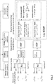
- Fig. 3 shows schematically how the design of the front-end antennas of the mutually incoherent apertures fits into a processing chain, in principle for radar and radio-frequency applications, where digital beamforming is done with group-sparse reconstruction, cf. Section PRIOR ART ON PROCESSING WITH MUTUALLY INCOHERENT APERTURES.
- the optimal design by inducing mutual sidelobe cancellation among matched filter responses of the individual virtual apertures, reduces ambiguity in the selection of the group of hypotheses that maximizes the combined response.
- Near-field models can be used for embodiment 1A as follows.
- the range can be obtained in a number of ways, e.g., using FMCW processing typical in automotive.
- the range of the objects can be assumed in any interval of values of interest. Tapering weights can also be incorporated as in embodiment 1C.
- the computational cost of the min-max optimization (27)-(25) ultimately depends on the complexity of evaluation of the observation model, which grows linearly with the number of virtual pairs of Tx and Rx elements and consequently with the number of incoherent apertures, and therefore the complexity is comparable to the case of coherent array design.
- the observation model for far-field steering vector (11) is slightly faster to evaluate than the model of near-field steering vector (16).
- ERC is formulated for sparse signals with a specific support, rather than for all sparse signals simultaneously, which is sufficient for design because typically the models used for design assume a single target.
- the ERC is desired to be low to reduce correlation between atoms in ⁇ and atoms not in ⁇ . That is, max n ⁇ ⁇ ⁇ A ⁇ + a n ⁇ 1 quantifies the ambiguity between hypotheses with indexes in ⁇ and out of ⁇ .
- the block-diagonal structure accounts for the random phase between the two apertures, and we make the group-sparsity partition of columns wherein two columns belong to the same class if they correspond to the same hypothesis (that is, even though the ERC is defined for standard sparsity with 1-norm, we consider a partition over groups of columns corresponding to the same hypotheses). Without loss of generality, we assume that the array models are expressed in a common reference frame, so that corresponding hypotheses for each aperture have the same index.
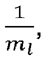
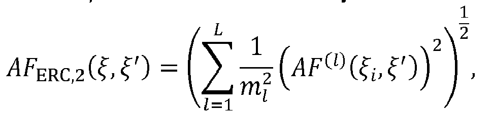
- the AFs are added with a relative importance factor proportional to 1 m l , i.e., inversely with the number of samples (or antennas), and ii) the fact that the 1-norm is used in the definition of ERC (instead of the 2-norm as in the group-sparsity norm ⁇ x ⁇ 2,1 ), is responsible for the fact that the AFs are added linearly and not quadratically in contrast with the metric in embodiment 1.
- the metric of embodiment 1 has a direct relationship to atom/group selection in BOMP through the combined matched-filter response (in turn related to gradient steps of MP and ITA in their extension to incoherent apertures) but this embodiment suggests, among other things, that the atom/group selection criterion of BOMP can be modified to exploit other optimality conditions.
- the concentrated log-likelihood for one snapshot results from solving s ( l ) for each aperture l , as follows, min s l ⁇ C ⁇ y l ⁇ a l ⁇ s l ⁇ 2 .
- the synthesis of antenna positions for each of the apertures can be defined as in (27).
- the signal model for individual apertures a ( l ) ( ⁇ ) is general.
- far-field and near-field models can be used for the optimization as described in embodiment 1.
- Previous embodiments characterize the optimal array layouts of multiple apertures and optional optimal tapering in such a way that posterior processing is enhanced even when information is combined incoherently.
- the proposed design optimization has been motivated by group-sparse reconstruction with BOMP in embodiment 1, recovery conditions for Compressed Sensing in embodiment 2, and Maximum likelihood in embodiment 3.
- Fig. 7 illustrates an instance of four mutually incoherent apertures in the front and on the rear of a vehicle, where the FoVs are represented with cones whose radii illustrate the detection range and overlapping areas are regions where optimization of antenna elements is coupled between apertures.
- the driving principle is parallel to the one in previous embodiments.
- a number of Tx, Rx antenna elements were optimally placed in multiple mutually incoherent apertures with efficient use of the available space thanks to mutual sidelobe cancellation between apertures.
- the synthesis method concerns stepped-frequency pulses or stepped-frequency continuous-waves (SFCW) and enables a reduced number of steps/pulses in each coherent bandwidth, which reduces measurement time and allows to avoid occupied bands of the spectrum.
- the resulting sparse waveform synthesis can be employed for range (and possibly Doppler) estimation using efficient Compressed Sensing algorithms including BOMP, similarly to the beamforming process based on group-sparse filtering in Fig. 3 .
- this optimization has applications in ground penetrating radar, spectrum management, and SFCW for automotive radar.
- the design according to this model presumes a processing mechanism that allows for incoherent combination of signals. That is, in the processing of signals when the angle of the targets is initially unknown (e.g., for range and/or Doppler estimation), using the proposed design of mutually incoherent apertures and waveform synthesis, the contribution to the phase of the frequency samples a ( l ) ( r k ), a ( l' ) ( r k ) collected by any two pairs (Tx ( l ) ,Rx ( l ) ), (Tx ( l' ) ,Rx ( l' ) ) in different virtual apertures l,l', due to the unknown angle of each target k and the diversity of antenna positions, is factored out and regarded as random as part of s k l and s k l ⁇ , cf. (19). Therefore, the proposed design is compatible with the design setup that we advocate, and, by improving the associated ambiguity function for the mutually inco
- Fig. 8 illustrates a scenario of waveforms for Tx elements in mutually incoherent apertures.
- Each transmitter has available a bandwidth for selection of SFCWs.
- a stepped frequency waveform or set of simultaneous frequencies can be selected, and the proposed embodiment describes the combined optimal selection across all mutually incoherent bandwidths.
- M m 1 + ⁇ + m L"
- F l ⁇ R is the available spectrum for aperture l , depending on constraints such as occupied bandwidth, or minimum separation between frequencies.
- Transmission times in TDM MIMO can be designed across multiple incoherent slow-time sequences to optimize non-ambiguous Doppler bandwidth and resolution.
- all transmitters can be considered as incoherent in cases including a) they are actually in incoherent apertures as described in previous embodiments, and b) cases where is desirable to decouple Doppler and DoA because there is an unknown phase difference between transmitters caused by the unknown target angle.
- transmission times of the pulse/chirps for each transmitter can be optimized to achieve mutual sidelobe cancellation in Doppler domain under incoherency according to the following, min t 1 ... t M f SLL t 1 ... t M c s . t .
- the signal model for Doppler estimation in terms of slow-time samples after preliminary range processing, at a given range frequency bin is mathematically equivalent to the steering vector of the far-field model (11). As time orthogonality is necessary for TDM MIMO waveforms, no simultaneous chirps or pulses should be allowed between different transmitters, which is captured by the domain .
- This embodiment addresses the problem in TDM MIMO with several Tx elements where the long dwelling time between consecutive chirps transmitted by the same Tx element, reduces the maximum non-ambiguous Doppler frequency, thus making the system unsuitable for high velocities of the target.
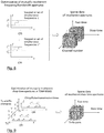
- Fig. 9 illustrates the optimization of transmission times for non-simultaneous chirps for two generic mutually incoherent transmitters over their respective coherent processing intervals, and also depicts the associated data cube.
- the diagram shows an arbitrary sparse antenna configuration and an exemplary sequence of FMCW chirps in frequency-time axes, emphasizing the design of the transmission times.
- the corresponding designs are suitable for processing of incoherent signals using algorithms such as MP or ITA for incoherent aperturtes or BOMP which are reasonably efficient as pointed out in the preliminaries..
- u sin( ⁇ ) Electronic angle when array is linear in the y axis (more properly, the v -component of n ⁇ ) r > 0 Range, distance to target.
- ⁇ , ⁇ k ⁇ R q Generic parameter vector, which can refer to the parameter vector of target k.
- a ⁇ ⁇ C M Generic signal (spatiotemporal sampling) model can be particularized to Tx or Rx steering vectors a Tx ( ⁇ ) , a Rx ( ⁇ ), or virtual a Virt ( ⁇ ) (.) FF , (.) NF Scripts to represent far- and near-field, respectively.
- Super-index ( l ) indicates l th aperture. It can refer to physical apertures l ⁇ ⁇ 1, ..., L' ⁇ , or virtual apertures l ⁇ ⁇ 1, ..., L ⁇ .
- the virtual apertures are combinations of Tx and Rx sets in each of the physical apertures.
- L,L',L" Number of physical apertures, mutually incoherent virtual apertures, and number of mutually incoherent sets of stepped frequencies, respectively.
- m Tx ,m RX Number of Tx and Rx antenna elements in a MIMO coherent aperture
- m l ,M Number of antennas
- m l m Tx l + m Rx l in physical aperture l and in total
- M m 1 + ... m L' .
- m Virt l m Tx l ⁇ m Rx l
- m Virt : m Virt 1 + ⁇ + m Virt L . w , w ( l ) , w Total Weights for tapering in three cases, generic, in virtual aperture l , and across all virtual apertures.
- x l ⁇ C N Sparse reconstruction coefficient vector over hypotheses ⁇ ⁇ 1 ,..., ⁇ N ⁇ .
- AF ( ⁇ , ⁇ ' ) > 0 Standard ambiguity function defined for a generic signal model a ( ⁇ ) AF ( ⁇ , ⁇ ' ) :
- AF BOMP ( ⁇ , ⁇ ' ) Combined ambiguity function over all apertures for BOMP.
- AF ERC ( ⁇ , ⁇ ' ) Combined ambiguity function over all apertures for ERC.
Landscapes
- Engineering & Computer Science (AREA)
- Radar, Positioning & Navigation (AREA)
- Remote Sensing (AREA)
- Physics & Mathematics (AREA)
- Computer Networks & Wireless Communication (AREA)
- General Physics & Mathematics (AREA)
- Electromagnetism (AREA)
- Variable-Direction Aerials And Aerial Arrays (AREA)
- Radar Systems Or Details Thereof (AREA)
Abstract
Description
- The present invention relates to the design of optimal antenna arrays for radar and radio-frequency applications comprised of mutually incoherent apertures that enable high angular resolution and localization estimation with unpreceded flexibility in usage of available space, and without need to synchronize widely separated transmit and/or receive antenna elements, avoiding the phase errors associated to lack of synchrony, deformations, and vibrations, and making unnecessary techniques such as auto-focusing or blind calibration between apertures that would require several snapshots, while maintaining a combined effective array factor with low sidelobes, all these characteristics suitable for applications to automotive radar for advance driver assistance systems (ADAS), ground-penetrating radar, synthetic aperture radar, medical imaging, navigation systems, and communications. The present invention also relates to a method for selection of waveform in a set of mutually incoherent apertures for radar and radio-frequency applications.
- High-resolution direction of arrival (DoA) estimation has crucial importance in most radar and communication systems. In highly automated driving, functions such as lane change assist and collision avoidance systems require high angular resolution in both forward and rear-facing radars to discern the lane of other vehicles and obstacles at long distances, especially at high speeds, cf.
Fig. 1 . The necessary aperture size and number of transmit and receive elements increase the required space and complexity of the hardware to achieve synchronization, particularly at high frequencies, which poses a challenge on the overall design and raises the cost. The disclosed invention presents a design method for synthesis of antenna element positions of mutually incoherent apertures, which relaxes the constraints on required physical space and synchronization associated to prior art on design of coherent apertures, while ensuring a satisfactory performance of angular estimation. - The problem of optimizing antenna element positions to achieve a desired beam-pattern, to our knowledge has been addressed only in the case of a single coherent aperture.
- The physical model used in prior art for optimization of antenna element positions considers a geometric arrangement of antenna elements that by coherent transmission produces a so-called radiation or beam-pattern, referring to the power directionality when certain complex amplitudes are applied to the radiating antennas through a beam-former network. By reciprocity of transmission and reception, this model also represents the estimation method of beamforming or Delay-and-Sum wherein the powered received in any hypothetical direction is quantified for a given direction of the emitting or reflecting object. Formally, in the far-field approximation, i.e., planar wave fronts, the power as a function of direction for a linear array of omnidirectional antenna elements (transmitters or receivers) at positions [y 1, ..., yM ] ∈(we present the three dimensional case next) is given by the so called array factor


Fig. 2 shows the model of planar wave fronts for azimuth and elevation angle with respect to boresight. In the next section we discuss the model for the antenna pattern, which in (1) is assumed omni-directional. - For an arrangement of antenna element positions in 3-dimensional space,

Fig. 2 ), the array factor is


- To generalize the concept of array factor to more general sampling schemes in signal processing, it is convenient to define a notion of ambiguity function [1]. Consider a spatial or temporal signal model given by


- The ambiguity function can be defined in terms of the scalar product between the spatial or temporal signals a(ξ), a(ξ'), with parameter vectors ξ,
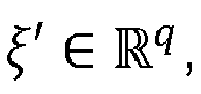


- Here we emphasize the dependence on the positions of the antenna elements (or, in further extensions, waveform frequencies or temporal sampling instants), and

- We make the following remarks with special emphasis on array design, some of them may not be readily available in the literature, especially for design in multi-dimensional problems, and are considered preliminaries:
- (i) The evaluation of metric (5) is itself a nonlinear and non-concave
1Note that when a(ξ) is a function instead of a finite vector, the scalar product in the corresponding Hilbert space is expressed as an integral. maximization for a candidate array. The sidelobes represent local maxima. Global optimization methods to solve this problem are necessary when ξ is multi-dimensional and when sidelobes are sharp. - (ii) Some parametrizations of the signals produce a dependency of the mainlobe width on the target parameters ξ, and therefore we consider a caliber c ≡ c(ξ) with an analogous dependency to reflect said physical property. For instance, the mainlobe width for angular estimation in terms of ξ = [φ,θ] depends on the apparent aperture of the array from the direction of the target. (In the case of a linear array perpendicular to boresight, the apparent aperture as a function of azimuth φ is scaled as

- (iii) In multi-dimensional problems, another choice is the norm used to quantify the distance ∥ξ - ξ'∥ p , or, alternatively, the distance can be measured and constrained entry-wise if the feasible or desired resolution is different in each parameter. Alternatively, the axes can be scaled or a scaling factor can be applied in ∥ρξ ⊙ (ξ - ξ'∥ p for

- (iv) The dependence on amplitude tapering weights (also called windowing or apodization) can be included in the description of the signal model a(ξ), i.e.,


- (v) The antenna pattern for all the antennas


- (vi) In the case of MIMO signals after match filtering, c.f. [6], the antenna pattern is incorporated using (7) as follows, a Virt(ξ) = ãTx (ξ) ⊗ ãRx (ξ), which is equivalent to

The FoV or domain for the parameters [ξ min,ξ max] in the specified reference frame is computed as the union of the supports of the entries in APO(ξ), or APO Virt(ξ) in the MIMO case, thresholded at a desired level of power decay P decay :
- (vii) An additional penalty term on the MLW is often included in the far-field case, cf. [7],
CN105426578B . (Note that the caliber induces a limit on the width of the mainlobe, beyond which the mainlobe is penalized as a SLL, but it is not a penalty on the MLW when the MLW is thinner than the caliber.) - The optimization of the element positions for models (1) or (2) to minimize the side-lobes for a given caliber function, is given by the nonlinear optimization problem,


- The optimization above implicitly constrains system cost and power. In particular, the number of antennas and the available space are given. In transmission, it is desirable to use equal power at the radiating antenna elements, |bi | = 1, to increase power efficiency and simplify the operation of the amplifiers. For reception, there is no inconvenient in using digital weighting at the available channels and these can be included as optimization variables as observed above. The phases of bi can be used for steering in transmission both in phased arrays and possibly in MIMO arrays but the scenario of steering in transmission is not addressed in this invention, which is focused on optimization of antenna element positions and tapering in post-processing for incoherent apertures.
- Next, we describe some properties of the far-field and near-field models and the relationship with other sampling schemes and waveform design, and review information theoretic metrics and statistical bounds on DoA estimation performance that simultaneously trade-off the SLL and the MLW.
- To relate the generic ambiguity function in (4) and the array factor (1), we define the far-field steering vector for the
linear array 


- The AF for model (11) verifies, for Δu := u - u', that


- This is a formulation commonly used for array design, cf. [2] [3] [4]. As mentioned above, it is common to add a complementary penalty term to optimize the MLW, cf. [7],
CN105426578B . - In cases where the array has specific structures, some quantities can be expressed analytically, e.g., for symmetric linear arrays
US3877033A , the array factor can be expressed as a product in terms of antenna positions, which allows to create nulls at desired angles and control the sidelobe level, and for circular ring arrays,EP2949002A1 (see alsoWO2014114993A1 ), it is possible to derive some optimality conditions for the rings' radii. - The far-field model has the advantage of fast processing using the Fast Fourier Transform (FFT) and other beamformers like MUSIC and ESPRIT. For design, using the far-field is not incompatible with using the angular variables φ,θ instead of the spatial frequencies [u,v,w] to parametrize the array factor. Indeed, the design of the arrays can be performed using the parametrization in terms of [φ,θ], even if it fails to satisfy the symmetry relation in (13) which in any case is unnecessary for (5).
- Another consequence of the far-field model is that the MIMO case for orthogonal waveforms can be written as the SIMO case in terms of the positions of the virtual Tx-Rx pairs (e.g., after matched-filtering, c.f. [6]), given by the Kronecker sum

- The near-field model for DoA estimation is a more realistic in some applications like medical imaging and also for automotive radar using arrays of certain aperture. Here we review the geometric aspect of this model that concerns the path of the signals from transmitters to object and back to receivers. For further reference, we refer to works on Taylor approximations and studies of model mismatch [9]. For the purpose of this disclosure, it suffices to introduce the exact geometric model. Following [10], the near-field steering vector for receive antennas pm = [xm,ym,zm ] T and an emitter object at distance r > 0 is given by

- By the reciprocity of transmission and reception, the corresponding near-field steering vector for transmission


- Note that the dependency of the near-field virtual steering vector on antenna positions is not through the virtual array in (15). Nonetheless, we can still refer to such coherent sets of Tx and Rx elements as a virtual aperture, which will be convenient when we define multiple such mutually incoherent apertures. Also, the range r is a parameter that has a different treatment depending on the application and for design purposes it can be assumed in a certain interval.
- Several data models in radar signal processing are usually transformed into frequency estimation of a sum of complex tones [11]. Analogous models include (a) DoA estimation under the far-field model using the electronic angles, and (b) Doppler estimation, where instead of having dependence on the antenna locations, there is a dependence on the carrier frequency and on the pulse repetition interval or non-uniform transmission times of the pulses. Another equivalent model is range estimation using a waveform with time-multiplexed or simultaneous frequencies, illustrated next. This waveform finds applications in ground penetrating radar [12], and SFCW for automotive radar [13] [14]. For simplicity, consider a transmitter and a receiver at the same location. The transmitter transmits a set of sinusoids with frequencies


- Optimization metrics that have been applied for array design alternative to the SLL and MLW of the ambiguity function, include the Bayesian Cramer-Rao Bound (BCRB), [16],
WO2009140998A1 , the Weiss-Weinstein Bound (WWB) [17] [18], and the Ziv-Zakai bound (ZZB) [19]. These have the following disadvantages: The BCRB is an asymptotic predictor of performance in the limit of high SNR or many snapshots, namely, it is related to the MLW and does not consider sidelobe ambiguity [7] and therefore it has to be combined with other metrics. On the other hand, metrics like the WWB or the ZZB are tighter bounds on the mean-squared-error (MSE) and are shown to capture big errors due to sidelobe ambiguity but they have drawbacks shared by all such bounds on the MSE, including the numerical evaluation of the Bayesian MSE itself [20]: (i) By definition they average the errors, which implies that worst-case scenarios due to high sidelobes are averaged with small contributions due to low sidelobes or due to other high sidelobes that are very close to the mainlobe. For this reason, these metrics favor array factors with sharp high sidelobes that produce errors with low probability or very close to the mainlobe, undesirable if the intention is to penalize all false alarms equally or to improve performance in the case of two scatterers. (ii) It is hard or impossible to derive analytic expressions of these bounds for more realistic signal models for angular estimation other than far-field, and numerical calculation of associated integrals without analytic formula is computationally expensive [20]. - Model (2) concerns a single coherent aperture because the signals of the different antennas are combined with known phases. In the scenario of interest of highfrequency radar, including but not limited to 77GHz, the literature on array design considers the optimization of antenna element positions only in said case of coherent apertures [2] [3] [4]. Work [21] was the first to consider this problem, and more recently the available computational power has popularized nonlinear global optimization methods such as genetic algorithms, particle swarm optimization, and simulated annealing [22]. The optimization has also been performed for non-planar arrays, including conformal arrays [8]. In the case of prior patent applications, again only the case of coherent arrays is studied, as we outline next with some exemplary works.
-
US3877033A describes a synthesis method of non-uniform arrays with uniform amplitudes (following the seminal work by the author in [21]) with a much lower sidelobe-level of the radiation pattern than the uniform counterparts, based on a factorization of the array factor, normally given by a sum of cosines for symmetric arrays, in terms of a multiplication of cosines in terms of the element positions, which yields a sequential and computationally fast method for optimal placement of an arbitrary number of antenna elements. -
WO2009140998A1 describes a method for thinning a given array (i.e., removing elements from an initially uniform array) using as optimization metric a combination of the angular estimation performance and the sidelobe level. The former is quantified in terms of the MSE or a lower bound thereof such as the CRB. -
EP2949002A1 (see alsoWO2014114993A1 ) describes a method for joint optimization of element positions and dimensions for planar sparse arrays, especially circular ring arrays. The optimization method makes some assumptions about the structure of the array to employ certain analytic optimality conditions.CN105426578B presents an optimization method for planar arrays for MIMO Synthetic Aperture Radar. The optimization of SLL and MLW is performed using genetic algorithms. - These works assume coherency between all the antenna elements. The disadvantages of coherent apertures are the following:
- i. Require a larger physical aperture to increase resolution;
- ii. Require synchronization, which entails hardware complexity and cost, particularly at high frequencies, and thus less mounting flexibility;
- iii. Are subject to phase errors due to fabrication inaccuracies, and also deformations and vibrations during operation;
- iv. The sidelobe level can be high if a big separation between apertures is imposed by design constraints, particularly in vehicles.
- As noted above, the main assumption in all previous work is that the signals from all the antennas are combined with the intended phase in transmission or, reciprocally, that all phase differences can be measured in reception. In contrast, in the method according to the present invention, a model is considered where a random initial phase is accounted for between subsets of antenna elements. We refer to this model as having mutually incoherent apertures.
- In previous section we have argued that prior art has not addressed a model of mutually incoherent apertures for design and/or optimization. Here we introduce the model for mutually incoherent apertures and review prior art that has addressed this model for processing signals. Consider a one-snapshot signal model after any required digital signal processing. In radar, the digital signal processing can optionally include match-filtering for range-Doppler processing or, typically in automotive radar, 2D-FFT. The following signal model can include spatiotemporal sampling and is not restricted to angle estimation, thus broadening the applicability of the disclosed invention for design of optimal non-uniform sampling and illumination with stepped frequencies under incoherency. Namely, the measurements are grouped for each coherent aperture, and can refer to time, frequency, or spatial samples.
- In the case of a single coherent MIMO aperture, there is only one virtual combination of sets of Tx and Rx elements. In the case of multiple (mutually incoherent) MIMO apertures, we define the virtual apertures as the combinations of sets of Tx elements and Rx elements in each of the apertures. The signals associated to these virtual apertures are mutually incoherent. It is also possible that one aperture does not contain Tx or Rx elements. The measurement model for each virtual aperture l ∈ {1,...,L} is defined as follows. For a sum of K sources, each with parameter vector


embodiment 3 where we introduce the likelihood under Gaussian models. That is, we consider the deterministic ambiguity function associated to the geometry of the samples. The signal models for each of the blocks,
- Methods for processing signals from incoherent apertures for model (19) have been developed, including techniques for the following scenarios: Synthetic Aperture Radar (SAR) or inverse SAR (iSAR), where auto-focusing [24] and blind calibration [25] techniques are used in post-processing to compensate for possibly unknown translation and orientation of the platform or the target; Distributed radar where incoherent processing via group sparsity has been used for delay estimation [26], iSAR [27], or tracking [28], as well as in passive radar networks [29]. In other scenarios like Radio-astronomy, synchronization is possible at low frequencies. In these works there is no mention to design and optimization principles of incoherent apertures.
- We also note that a previous invention by the authors, filed as
EP18179827 - In a previous section we have reviewed the equivalence between mathematical models for DoA estimation (under far-field signals) and Doppler and delay estimation, which allows to extend the novel disclosed techniques for design of mutually incoherent apertures to the case of waveform design also under mutually incoherent bandwidths. The principles for such design have not been presented earlier in the case of multiple mutually incoherent apertures.
- In the case of coherent time/frequency apertures, [15] presents a radar system architecture based on Compressed Sensing for high range resolution [30], and ISAR, where only specific frequencies are generated, thus using the spectrum more efficiently and reducing the rate of sampling data. With similar principles, [31] explains a method for measurement acquisition and delay estimation based on Doppler focusing for increasing SNR and guaranteeing sparsity in fast-time domain (i.e., range domain). This work estimates the delay using Compressed Sensing with a set of Fourier coefficients, which can be obtained via direct sampling [32], or sampling different spectral bands using a sub-Nyquist measurement-acquisition process denominated Xampling, and then matching the Fourier coefficients digitally [33]. Other design techniques for sub-sampling a signal include multicoset sampling [34], which is amenable to CS techniques [35]. This model has been used for the optimization of spatially variant apodization (tapering) assuming coherency [36].
- Works related to cognitive waveform design include [37], which presents a characterization of optimal pulse repetition frequency and channel selection based on optimization of the WWB in a given domain or field of view of the parameter of interest, e.g., Doppler frequency and DoA. Waveform optimization has been studied in numerous works [38] in relation to avoiding certain occupied bands of the spectrum while optimizing filter performance, but the optimization principles considered do not employ ambiguity functions or similar metrics under incoherency between multiple apertures.
- In the case of optimization of pulse/chirp transmission times, the following works and inventions are the closest:
US7142153B2 presents hardware and a method based on stepped-frequency pulses for range-Doppler estimation. This invention does not consider design optimization principles. -
US9448302B2 - Multiple works have studied the problem of optimization of switching patterns, or pulse transmission times, in TDM MIMO using ambiguity functions [41], [42] or statistical performance metrics that capture sidelobe level (as aforementioned [37]). Recent work [43] considers non-uniform arrays and proposes a model for optimizing the sidelobes according to a spatio-temporal ambiguity function, thus increasing the maximum non-ambiguous Doppler frequency. However, again these works do not consider mutually incoherent apertures or the phenomenon of mutual sidelobe cancellation between them.
- In summary, none of the previous approaches have focused on design principles for incoherent apertures, either spatially, for optimal placement of antenna elements, or in frequency, for the selection of frequency bands, or in time, for the optimization of pulse transmission times in slow-time mutually incoherent transmission sequences. None of them enhance the properties of the effective combined ambiguity function or matched-filter response in said case of mutually incoherent apertures, and there is no mention of principles for effective mutual cancellation of sidelobes in the parameter of interest, DoA, range or velocity, under random initial phases between apertures in space, frequency or time.
- It is thus an object of the present invention to provide a method for synthesis of antenna array layouts and/or selection of waveform in a set of mutually incoherent apertures for radar and radio-frequency applications which allows a cancellation of sidelobes at an optimal usage of space and number of elements, and/or bandwidth and measurement acquisition time.
- The object of the invention is achieved with the method according to
claims - In the proposed method, a synthesis of antenna array layouts is described based on mutually incoherent apertures in terms of an optimization problem for given constraints on the number of mutually incoherent apertures, the total number of Tx and Rx elements, the maximum size of each aperture, and the field-of-view. Other design hyper-parameters for near-field models may include the set of ranges over which the metric is averaged. The design method includes the provision of a metric with ambiguity functions formulated for Block Orthogonal Matching Pursuit (BOMP), Tropp's Exact Recovery Condition (ERC), and Maximum Likelihood, for a signal model that includes random initial phases between apertures, and the selection of transmit and receive antenna locations according to said metric based on optimization of the corresponding ambiguity functions. The optimization is performed such that a sidelobe level (and/or features dependent on the sidelobe level) associated to said ambiguity functions over a number of dimensions corresponding to one or several parameters of interest, including azimuth and/or elevation, is minimized.
- The proposed method for selection of waveform accordingly includes the provision of a metric with ambiguity functions based on a signal model that includes random initial phases between apertures, and the selection of frequencies and/or pulse transmission times according to said metric based on optimization of the ambiguity functions such that a sidelobe level (and/or features dependent on the sidelobe level) associated to said ambiguity functions over a number of dimensions corresponding to one or several parameters of interest, including range and/or Doppler, is minimized.
- The principle of the invention for design of array layouts of mutually incoherent apertures is the following. By exploiting the disclosed optimal designs, group-sparse reconstruction algorithms and other beamformers exhibit an improved estimation performance because the design method allows to optimize the resolution of the mutually incoherent apertures by using more effectively the available space without the need to keep a low sidelobe level in each individual aperture thanks to the mutual cancellation of sidelobes.
- The benefits of the proposed method include
- I. Unnecessary synchronization among widely distributed antenna elements. Transmission and reception synchronization is a challenge, particularly at high frequencies (e.g., 77GHz in automotive radar), which adds complexity and cost to the system. The disclosed design method can achieve comparable or better resolution and sidelobe level than a bigger and costlier coherent aperture by combining two or more smaller incoherent apertures, contrary to existing perception that to increase resolution for a given sidelobe level is necessary to have bigger apertures.
- II. Flexible use of space. A benefit of avoiding big coherent apertures is that our designs can be more flexibly mounted in a vehicle, in a distributed fashion, using the available space without need for cables and systems to avoid or compensate vibrations.
- III. Elimination of phase errors introduced by deformations and vibrations of separated apertures. The smaller each coherent aperture, the smaller the effect of deformations, dilations and vibrations, which introduce phase errors that are significant at high frequencies, e.g., 77GHz in automotive radar. Note that the distance between incoherent apertures does not need to be known with wavelength accuracy because inter-aperture phase differences are not employed.
- IV. Multi-functionalities and array constellations. Our method allows to flexibly optimize sets of apertures with different and specialized requirements in terms of field-of-view or range of operation.
- The proposed method and exemplary array layouts are particularly suited, given the above benefits, for design of a constellation of incoherent apertures for automotive radar, optimized for short, medium and long range functionalities and possibly with full 360° coverage to enable at low cost all advance driving assistant systems, from lane change assist, to collision warning and emergency braking. Nonetheless, it can also find applications in airborne and satellite radar, synthetic aperture radar, remote sensing, communications, and navigation systems.
- The proposed design procedure is described in detail in the following by way of detailed mathematical descriptions of the optimization metrics, design variables, and constraints in connection with the drawings, wherein:
-
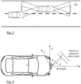
Fig. 1 depicts a traffic scenario where a vehicle has to change to the adjacent lane because of the presence of an obstacle but a second vehicle behind is using that lane to overtake the first vehicle. -
Fig. 2 depicts a schematic exemplary configuration of antenna array apertures along with a 3-dimensional reference frame representing the azimuth and elevation angles of a planar front wave impinging the arrays. -
Fig. 3 depicts a block diagram of the basic architecture of an exemplary radar system including the front-end with the optimal antenna array design for multiple mutually incoherent apertures, and the processing chain exemplifying the processing of the signals using group-sparse reconstruction. The upper part arrows illustrate that the synthesis of antenna positions and digital tapering result from optimizing a metric that enhances the processing of signals from the mutually incoherent apertures. DSP stands for digital signal processing. Note that the number of coherent (but mutually incoherent) physical apertures, L' (with Tx and Rx elements), is different than the total number of virtual apertures, L, which result from combinations of coherent sets of Tx and Rx elements. -
Fig. 4 depicts a schematic description of the design choices that need to be specified for the optimization of antenna element positions, including i) number of mutually incoherent apertures (e.g., one in the center of the bumper and two on the sides, but the possible configurations are not limited to these), ii) the available space for each aperture, iii) the number of Tx and Rx elements, and iv) the field-of-views. -
Fig. 5 depicts the coordinate transformation of azimuth angle between two reference frames associated to two antenna arrays or apertures with different orientations. It additionally shows that a target may not be in the FoV of both antenna arrays or apertures. -
Fig. 6 illustrates an example of the result of mutual sidelobe cancellation between the mutually incoherent virtual apertures. It shows the combined and individual ambiguity functions of an instance configuration with three mutually incoherent linear apertures, a central 3x4 MIMO aperture and two apertures on the sides with 4 Rx elements each, optimized jointly over a FoV of ±60°. Since there are transmitters only in the central aperture, the mutually incoherent virtual apertures are then defined by the Tx,Rx-MIMO subarrays (Center-Left), (Center-Center), and (Center-Right). The final sizes after the optimization of the subarrays is indicated in the legend: 1.9cm for Rx sub-array on the left, 3cm and 2.3cm for the Tx and Rx sub-arrays on the center, and 1.6cm for the Rx sub-array on the right. (The actual antenna positions are not provided for this example.) The vertical lines represent the caliber and the limit of the FoV, thus delimiting the region where the effective combined SLL is minimized. The legend also shows the resulting length of each aperture. -
Fig. 7 illustrates an example for multiple radar array apertures in a vehicle with an exemplary plant view of the overlapping FoVs in azimuth. The radius of each cone illustrates the possibly different detection ranges of the antennas (not at scale). -
Fig. 8 illustrates a scenario of waveforms for Tx elements in mutually incoherent apertures. Each transmitter has available a bandwidth for selection of SFCWs. In each coherent bandwidth, a stepped frequency waveform or set of simultaneous frequencies are selected according to the optimization proposed. -
Fig. 9 illustrates the optimization of transmission times for non-simultaneous chirps for two generic mutually incoherent transmitters over their respective coherent processing intervals, and also depicts the associated data cube. The diagram shows an arbitrary sparse antenna configuration and an exemplary sequence of FMCW chirps in frequency-time axes, emphasizing the design of the transmission times. - Next we describe the method for the synthesis of antenna element positions under mutually incoherent apertures.
- We start with some preliminaries on group-sparse reconstruction.
- The estimation of the parameter vectors


- This matrix is sometimes called dictionary. Note that if a given hypothesis ξ j
0 does not belong to
0 ) = 0. The coupling constraint between mutually incoherent virtual apertures is induced by a group-sparsity constraint ∥x∥2,1 < ε, for suitable ε > 0 in terms of the block-norm


- The quantity

- Regarding the above model, we make two observations: (i) the measurement fidelity constraints (20) do not couple the phase differences between mutually incoherent virtual apertures because these are assumed arbitrary due to lack of synchronization, vibrations, etc. In particular, the sparse reconstruction coefficients x =

Fig. 4 , and where some hypotheses are not present in both field-of-views, cf.Fig. 5 . This aspect is revisited in the embodiments below. - To solve problem (19) there are available several group-sparse reconstruction algorithms analog to ones for standard sparsity. The best known in this context is the algorithm BOMP [44], which has the following strategy for group selection (or block of atoms) in the case of incoherent sensors [27]. For L array apertures and an N-long grid of hypotheses for the reconstruction, BOMP first estimates the matched-filter response for each coherent array l,


- Further steps of BOMP can be found in [27]. For the implementation of this exemplary algorithm, steps (22) and (23) are the only ones that combine information among apertures and also the relevant steps for the motivation of our design method. More importantly, we note that the matched-filter computations in (22) are the basis of other reconstruction algorithms such as Matching Pursuit (MP) [45] or iterative thresholding algorithm (ITA) [46]. In other words, the defining characteristic of the further (non-described) orthogonal projection of BOMP for the update of the residual is unnecessary for motivating the invention. The fundamental principle is the combined matched filter response, which is used in BOMP for atom selection (23), and is also used in algorithms such as MP or ITA for the gradient direction (cf. [47] for a unified description of these methods and efficient implementations).With these preliminaries, we are in a condition to describe the invention.
- Here we propose an ambiguity function for sidelobe level optimization motivated by the combined matched-filter response (22) as follows. We assume a signal for one target,


- This defines an effective combined AF in the grid {ξ 1,...,ξN } that is the average of the squares of the AF for the individual virtual apertures, where AF (l)(ξ,ξ') := |a (l)(ξ)H a (l)(ξ')| and we recall that a (l) (ξ') is the lth virtual aperture signal model in (19). Note that while the AF and the notion of sidelobes are defined for a continuum of hypotheses, the matched-filter response in (22) is defined for a dictionary of hypotheses over a discrete grid {ξ 1,...,ξN }. Since this grid is arbitrary, we make the natural extension outside the grid, which we term effective ambiguity function for mutually incoherent apertures based on BOMP:

- The sidelobe level is independent of the grid and is defined as usual outside of a band defined by the caliber function c(ξ') and inside the FoV [ξ min,ξ max],


- With a total number of antennas among the apertures m 1 + ··· + mL' = M. The interval of optimization for the search of the highest sidelobe is defined as the union of the intervals or FoVs over all the virtual apertures, i.e.,

- We recall that for each virtual aperture, the FoV

- Then, the optimal antenna positions are obtained as the solution to

- Here


Fig. 4 illustrates the relevant parameters of the optimization: the number of physical apertures, L', the number of transmitters and receivers in each,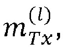
 , and the FoV of each virtual aperture


-
Fig. 6 shows an example of the effect of mutual sidelobe cancellation as a result of optimization (25). The optimization uses square antenna patterns over the FoV ±60°, and uses the far-field model. The configuration was pre-selected to be a central 3x4 MIMO aperture, and two "satellite" apertures on the sides with 4 Rx elements each, all linear along the y-axis and with the same perpendicular orientation. The maximum available size for each aperture was, from left to right, 4cm, 7cm, and 4 cm. Note that in general the number of mutually incoherent apertures results from all the combinations of Tx and Rx coherent sub-arrays, but in this example there are Tx elements only in the central aperture, while there are receivers in all three apertures. Consequently, the mutually incoherent virtual apertures are then defined by the Tx,Rx-MIMO subarrays (Center-Left), (Center-Center), and (Center-Right). The final sizes after the optimization of the subarrays is indicated in the legend: 1.9cm for Rx sub-array on the left, 3cm and 2.3cm for the Tx and Rx sub-arrays on the center, and 1.6cm for the Rx sub-array on the right. The plot shows the individual AF of the three mutually incoherent virtual apertures and the combined effective AF according to (24), whose SLL is optimized. As a result of the optimization we observe that the sidelobes of the individual AF are mutually compensated in the combined AF. -
Fig. 3 shows schematically how the design of the front-end antennas of the mutually incoherent apertures fits into a processing chain, in principle for radar and radio-frequency applications, where digital beamforming is done with group-sparse reconstruction, cf. Section PRIOR ART ON PROCESSING WITH MUTUALLY INCOHERENT APERTURES. The optimal design, by inducing mutual sidelobe cancellation among matched filter responses of the individual virtual apertures, reduces ambiguity in the selection of the group of hypotheses that maximizes the combined response. We further note that the resolution cannot be improved with respect to a sufficiently dense array of maximum available coherent-aperture size, but a reduced number of antennas can be optimally located using more aggressively the available space of each aperture while ensuring that sidelobes are mutually cancelled despite the incoherent processing. In subsequent embodiments it is explained the optional possibilities of optimizing tapering weights and waveforms to further enhance the incoherent processing according to this principle. - Some noteworthy observations are the following:
- i) The parameters ξ and antenna positions are expressed in a common reference frame across all the apertures.
- ii) We use the convention that if there exists

Fig. 5 where the FoVs of the apertures do not overlap completely, e.g., in the near-field model, or the apertures have different orientations. This is an important aspect in the design of constellations of arrays presented in embodiment 4. - iii) We have made special emphasis on the distinction between physical aperture, where a set of coherent antennas are placed, and virtual physical aperture, that results from the combination of a coherent sub-array of Tx elements in one aperture and a coherent sub-array of Rx elements in the same or different aperture. This distinction is important for the implementation of the numerical optimization of the antenna positions but in the sequel, unless explicitly mentioned, we use for convenience aperture instead of virtual aperture and the distinction must be discerned from context.
- The optimization of tapering weights can be optionally included in (27) as follows.
- 1. For each virtual aperture, the ambiguity function AF (l)(ξ,ξ') in (24) is replaced by (6) in terms of a non-negative vector of weights w (l) of dimension
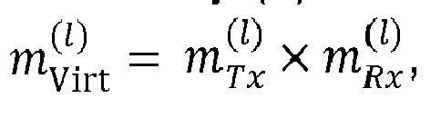

- 2. The search of highest sidelobe is performed as in (25), for candidate weights


Virt instead of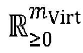
- 3. The optimization in (27) includes explicitly the dependency of the metric f SLL, BOMP([p 1 ,...,pM ],wTotal;c) on the variable wTotal (in addition to the antenna optimization or independently) over the desired domain. The domain of the weights can be a discrete library of candidate tapering weights or the continuous domain [0,1] m
Virt . The highest sidelobe function fSLL is non-convex and therefore global or discrete optimization methods are necessary. - Near-field models can be used for embodiment 1A as follows. In the case of the near-field steering vector (16), there is a dependence on the range or distance to the objects of interest, and we can replace (24) by
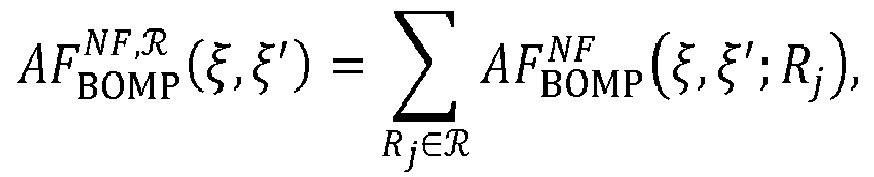


- The computational cost of the min-max optimization (27)-(25) ultimately depends on the complexity of evaluation of the observation model, which grows linearly with the number of virtual pairs of Tx and Rx elements and consequently with the number of incoherent apertures, and therefore the complexity is comparable to the case of coherent array design. We also observe that the observation model for far-field steering vector (11) is slightly faster to evaluate than the model of near-field steering vector (16). In the
next embodiments - In addition to the effective ambiguity function of
embodiment 1 that enhances the performance of BOMP, here we formulate a metric based on sparse recovery in Compressed Sensing called Tropp's Exact Recovery condition (ERC) [48]. This condition is concerned with standard sparsity rather than group-sparsity but is noteworthy making the connection for the signal model of incoherent apertures. - The ERC is formulated for sparse signals with a specific support, rather than for all sparse signals simultaneously, which is sufficient for design because typically the models used for design assume a single target. Formally, this metric is defined, for a dictionary of hypothesis analogous to (21) as

- The ERC is desired to be low to reduce correlation between atoms in Λ and atoms not in Λ. That is,

- We formulate the ERC (29) for the signal model (19) in the case of L = 2 mutually incoherent apertures (since the general case of L apertures is analogous), and assume a 1-source model corresponding to exactly one hypothesis in the dictionary (akin to a scenario without off-grid error), i.e., Λ = {i},

- The block-diagonal structure accounts for the random phase between the two apertures, and we make the group-sparsity partition of columns wherein two columns belong to the same class if they correspond to the same hypothesis (that is, even though the ERC is defined for standard sparsity with 1-norm, we consider a partition over groups of columns corresponding to the same hypotheses). Without loss of generality, we assume that the array models are expressed in a common reference frame, so that corresponding hypotheses for each aperture have the same index.
- Since the columns of A Λ={i} are independent thanks to the block-diagonal structure, the pseudoinverse can be calculated as


- In the cases where the signal model has a 2-norm equal to the number of samples or antennas, as in (13), then


- We make two observations: i) the AFs are added with a relative importance factor proportional to
embodiment 1. - In the limit when the spacing in the grid tends to 0, we obtain a notion of ambiguity function. This limit makes sense because we recall that the caliber in (5) prevents from computing cosine similarities at arbitrarily close parameters.) In the case of L apertures, the extension to a continuum of hypotheses yields our definition of effective ambiguity function for mutually incoherent apertures based on ERC,

- With regards to observation ii) above, if, alternatively, the 2-norm is used, we obtain

embodiment 1 has a direct relationship to atom/group selection in BOMP through the combined matched-filter response (in turn related to gradient steps of MP and ITA in their extension to incoherent apertures) but this embodiment suggests, among other things, that the atom/group selection criterion of BOMP can be modified to exploit other optimality conditions. - With this ambiguity function, the formulation of the optimization problem for the synthesis of antenna element positions is analogous to
embodiment 1. - The performance of maximum likelihood also provides a notion of ambiguity for model (19) in the case of one source (K = 1) with parameter vector


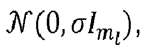

- The concentrated log-likelihood for one snapshot (i.e., a single measurement per aperture), results from solving s (l) for each aperture l, as follows,

- The solution is


l is the identity matrix of size ml , and P (l)(ξ) is the orthogonal projection onto a (l)(ξ),
- Next we explain the difference between parameter estimation and the metric optimized in this embodiment for design of incoherent apertures, which aims at increasing estimation performance. The estimation of the parameter ξ corresponds to maximizing the likelihood, or, equivalently, minimizing the negative log-likelihood given the aperture measurements,

- Accordingly, the notion of sidelobe refers to local minima for problem (31), which can cause ambiguous estimates in the presence of noise. The synthesis of antenna positions then requires reducing the effect of these local minima.
- Consequently, in this embodiment we define the ambiguity between ξ and ξ', for a one-scatterer signal y (l) = a (l)(ξ'), as

- We refer to the latter as effective ambiguity function for mutually incoherent apertures based on ML.
- As for previous ambiguity functions, the peaks of AF ML(ξ,ξ') can be called sidelobes (which correspond to local minima of (31)) and the objective of the design is to minimize them, in particular minimizing the highest sidelobe, SLL, which is defined as in (25) in
embodiment 1,
- This metric quantifies the sidelobes for pairs of distinct hypotheses ξ,ξ' for which the value of

embodiment 1. - Previous embodiments characterize the optimal array layouts of multiple apertures and optional optimal tapering in such a way that posterior processing is enhanced even when information is combined incoherently. The proposed design optimization has been motivated by group-sparse reconstruction with BOMP in
embodiment 1, recovery conditions for Compressed Sensing inembodiment 2, and Maximum likelihood inembodiment 3. In this embodiment we describe the possibilities for synthesis of antenna array layouts when a set of incoherent apertures is optimized according to any of previous embodiments for any desired FoV, including 360° coverage and for short, medium and long range functionalities.Fig. 7 illustrates an instance of four mutually incoherent apertures in the front and on the rear of a vehicle, where the FoVs are represented with cones whose radii illustrate the detection range and overlapping areas are regions where optimization of antenna elements is coupled between apertures. - The application of embodiments 1-3 to the design of constellations of arrays includes, but is not limited to, the following steps:
- 1. Consider the locations available for the array apertures that are considered mutually incoherent. This provides the number of mutually incoherent virtual apertures L, while the domain for the antennas, , always corresponds to the physical Tx and Rx in each physical aperture, l ∈ {1,...,L'}. The domains
 can be parametrized by curves or surfaces as discussed in Section PRELIMINARIES ON ANTENNA POSITION SYNTHESIS.
- 2. Select a number of Tx and Rx elements for each aperture. (If the number is variable, the proposed optimization has to be repeated for each considered case.)
- 3. Consider the radiation pattern of individual antennas in azimuth and elevation together with their orientations, summarized in the vector APO(ξ;µ). The orientations and further parameters of shape are collected in the vector µ, which can be optionally considered an optimization vector variable. This determines the FoV of each virtual aperture (cf. (8)) in the given reference frame and therefore the total coverage obtained by all the mutually incoherent apertures, cf. (26).
- 4. Consider the desired operational range of each aperture and the most appropriate signal model for optimization depending on desired functionality, including far-field, or near-field signals (cf. embodiment 1C). This sets the signal model for each aperture a (l)(ξ). (Recall that that measurement models across apertures must be written in a common reference frame.)
- 5. Optionally consider as additional optimization variables the tapering weights, according to embodiment 1B.
- 6. Consider either of the effective combined ambiguity functions in embodiments 1-3, defined in (24), (30) or (32), which characterize the MLW and the sidelobes.
- 7. Choose a feasible caliber function c(ξ) in the formulation of the metric (25) or in corresponding metrics in
embodiments 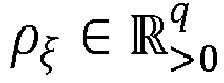
- 8. Solve the non-concave maximization (25) to compute the SLL for each candidate antenna positions (and possibly tapering weights).
- 9. Optionally consider other related features like MLW, according to desired specifications and set appropriate importance to each term in the final cost function analog to (10).
- 10.Solve optimization over antenna positions as in (27).
- 11. Repeat process for other candidate number of Tx and Rx elements or other design choices to evaluate the trade-off between performance and cost.
- 12.Test the performance with synthetic signals using any desired estimation algorithm (e.g., BOMP, other CS algorithm, ML, etc.) to evaluate the resulting arrays for direction of arrival estimation.
- In the next embodiment we present a method for waveform synthesis that is advantageous in certain scenarios using multiple incoherent apertures. We describe two embodiments: stepped-frequency waveform design for range estimation and design of slow-time sequences of pulses or chirps for Doppler estimation using mutually incoherent apertures.
- Multiple incoherent apertures also present an opportunity for waveform design. The driving principle is parallel to the one in previous embodiments. Previously, a number of Tx, Rx antenna elements were optimally placed in multiple mutually incoherent apertures with efficient use of the available space thanks to mutual sidelobe cancellation between apertures. In this embodiment, the synthesis method concerns stepped-frequency pulses or stepped-frequency continuous-waves (SFCW) and enables a reduced number of steps/pulses in each coherent bandwidth, which reduces measurement time and allows to avoid occupied bands of the spectrum. The resulting sparse waveform synthesis can be employed for range (and possibly Doppler) estimation using efficient Compressed Sensing algorithms including BOMP, similarly to the beamforming process based on group-sparse filtering in
Fig. 3 . As reviewed in the corresponding section on prior art, this optimization has applications in ground penetrating radar, spectrum management, and SFCW for automotive radar. - Next we formulate the method for waveform synthesis analogously to embodiments 1-3. The signal model for the incoherent apertures is constructed following (19) where the signal for each coherent bandwidth a (l)(ξ) is given by (17) and the parameter is the range ξ = r (or delay) for a given target, i.e.,


- As before, the design according to this model presumes a processing mechanism that allows for incoherent combination of signals. That is, in the processing of signals when the angle of the targets is initially unknown (e.g., for range and/or Doppler estimation), using the proposed design of mutually incoherent apertures and waveform synthesis, the contribution to the phase of the frequency samples a (l)(rk ), a (l')(rk ) collected by any two pairs (Tx(l),Rx(l)), (Tx(l'),Rx(l')) in different virtual apertures l,l', due to the unknown angle of each target k and the diversity of antenna positions, is factored out and regarded as random as part of


-
Fig. 8 illustrates a scenario of waveforms for Tx elements in mutually incoherent apertures. Each transmitter has available a bandwidth for selection of SFCWs. In each coherent bandwidth, a stepped frequency waveform or set of simultaneous frequencies can be selected, and the proposed embodiment describes the combined optimal selection across all mutually incoherent bandwidths. - The effective ambiguity function for the mutually incoherent apertures is constructed analogously to any of embodiments 1-3 using the AF for each coherent bandwidth (18), namely, AF (l)(ξ,ξ') = AFPC (Δr), and the corresponding SSL is obtained as in (24)-(25),

- The optimal allocation or selection of carrier frequencies between apertures can be formulated, analogously to (27), as


- Transmission times in TDM MIMO can be designed across multiple incoherent slow-time sequences to optimize non-ambiguous Doppler bandwidth and resolution. In Doppler estimation for TDM MIMO, all transmitters can be considered as incoherent in cases including a) they are actually in incoherent apertures as described in previous embodiments, and b) cases where is desirable to decouple Doppler and DoA because there is an unknown phase difference between transmitters caused by the unknown target angle. In these cases, transmission times of the pulse/chirps for each transmitter can be optimized to achieve mutual sidelobe cancellation in Doppler domain under incoherency according to the following,


 .
.
- This embodiment addresses the problem in TDM MIMO with several Tx elements where the long dwelling time between consecutive chirps transmitted by the same Tx element, reduces the maximum non-ambiguous Doppler frequency, thus making the system unsuitable for high velocities of the target. Using the above optimization of slow-time sequences over multiple transmissions, under incoherent apertures or if DoA is regarded as unknown, allows to cancel potential grating lobes and ambiguity.
Fig. 9 illustrates the optimization of transmission times for non-simultaneous chirps for two generic mutually incoherent transmitters over their respective coherent processing intervals, and also depicts the associated data cube. The diagram shows an arbitrary sparse antenna configuration and an exemplary sequence of FMCW chirps in frequency-time axes, emphasizing the design of the transmission times. The corresponding designs are suitable for processing of incoherent signals using algorithms such as MP or ITA for incoherent aperturtes or BOMP which are reasonably efficient as pointed out in the preliminaries.. - Other transmission parameters can be similarly designed because the effective ambiguity function of the combined apertures depends on them, and therefore the SLL can be evaluated for such transmission variables to also achieve mutual sidelobe cancellation and consequent non-ambiguous estimates while enhancing resolution at low hardware cost, as in the case of antenna array layouts in embodiments 1-4, or a shorter measurement acquisition time as in embodiment 5A, or non-ambiguous Doppler filtering with TDM MIMO with several transmitters even at high speed.
TABLE OF SELECTED NOTATIONS Notation Definition ,

Vector space of complex K-dimensional vectors or M × K matrices. ,


Euclidean space of dimension q, and octants with nonnegative and positive real numbers, respectively. ⊗,⊙ Kronecker product and entry-wise product, respectively. (.) T,(.) H Transpose and conjugate transpose, respectively. Im Identity matrix of size m. ∥.∥ p p-norm, for p ∈ [1,∞], defined for any vector  as
as

λ 0 ,k 0 Wavelength and Wavenumber k 0 = 2 π/λ 0 . 
3-dimensional coordinates for each of M antenna elements. 
Azimuth angle from boresight (x axis). θ ∈ [0,π] Elevation angle measured from polar axis (z axis). 
Normal vector to the unit sphere at angles φ,θ, n̂ := [cos(φ)sin(θ),sin(φ)sin(θ),cos(θ)]. [u,v,w] Components [x,y,z] of n̂. u = sin(φ) Electronic angle when array is linear in the y axis (more properly, the v-component of n̂) r > 0 Range, distance to target. ξ, 
Generic parameter vector, which can refer to the parameter vector of target k. 
Generic signal (spatiotemporal sampling) model; can be particularized to Tx or Rx steering vectors aTx (ξ), aRx (ξ), or virtual a Virt(ξ) (.) FF,(.) NF Scripts to represent far- and near-field, respectively. a Virt(ξ) Virtual steering vector, for far- or near-field in 

Antenna pattern, which is the power at ξ relative to its orientation. APO(ξ;wAPO ) 
Antenna pattern, power at ξ with respect to common reference frame depending on orientation of the antenna, where wAPO includes parameters such its pointing direction and shape. (.)(l) Super-index (l) indicates lth aperture. It can refer to physical apertures l ∈ {1, ..., L'}, or virtual apertures l ∈ {1, ...,L}. In the case of several MIMO array apertures, the virtual apertures are combinations of Tx and Rx sets in each of the physical apertures. L,L',L" Number of physical apertures, mutually incoherent virtual apertures, and number of mutually incoherent sets of stepped frequencies, respectively. mTx,mRX Number of Tx and Rx antenna elements in a MIMO coherent aperture ml,M Number of antennas, 

Number of virtual pairs of Tx and Rx elements in a given aperture 

w,w (l),wTotal Weights for tapering in three cases, generic, in virtual aperture l, and across all virtual apertures. 
3-dimensional coordinates for each of ml antenna elements in the lth physical aperture. 
Domain for antenna positions, including minimum separation. 
Domain for antenna positions of lth aperture. Note that 


Measurement signal at lth aperture. 
Measurement model (e.g., far-steering vector aFF , near-field steering vector aNF, or other sampling vector). 
Complex amplitude of source k, accounting for path propagation loss, target RCS, processing gain, and random initial phase associated to coherent aperture l. 
Matrix whose columns are the array model a (l) evaluated in points in a grid A (l) := [a (l)(ξ 1)···a (l)(ξN )], where {ξ 1,...,ξN } is the set of hypotheses for ξ (possibly ordered with lexicographic order). 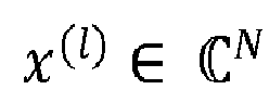
Sparse reconstruction coefficient vector over hypotheses {ξ 1,...,ξN }. AF(ξ,ξ') > 0 Standard ambiguity function defined for a generic signal model a(ξ) AF(ξ,ξ') := |a(ξ) Ha(ξ')|. AF (l)(ξ,ξ') Ambiguity function associated to the lth aperture. AF BOMP(ξ,ξ') Combined ambiguity function over all apertures for BOMP. AF ERC(ξ,ξ') Combined ambiguity function over all apertures for ERC. AF ML(ξ,ξ') Combined ambiguity function over all apertures for maximum likelihood. c ≡ c(ξ) Caliber function to determine neighborhood around mainlobe, beyond which the peaks of the ambiguity function are quantifies as sidelobes. fSLL ([p 1, ...,pM ];c) Cost function or metric that quantifies sidelobe level and related features of combined ambiguity functions (e.g., f SLL, BOMP for BOMP, and similarly for ERC, etc.) TABLE OF ABBREVIATIONS Notation Definition ADC Analog to digital converter AF Ambiguity function BOMP Block Orthogonal Matching Pursuit CPI Coherent processing interval CRB Cramer-Rao Bound DSP Digital signal processing ERC Tropp's Exact Recovery Condition FF Far field FMCW Frequency-modulated continuous-wave FoV Field-of-view ITA Iterative Thresholding Algorithm MIMO Multiple Input Multiple Output MLW Mainlobe width ML Maximum Likelihood MP Matching Pursuit NF Near field SFCW Stepped-frequency continuous-wave SLL Sidelobe level (height of maximum sidelobe) TDM Time domain multiplexing WWB Weiss-Weinstein Bound -
- [1] G. S. A. a. D. R. F. a. F. C. Robey, "MIMO Radar Ambiguity Functions," IEEE Journal of Selected Topics in Signal Processing, vol. 1, no. 1, pp. 167-177, 2007.
- [2] M. M. Khodier and C. G. Christodoulou, "Linear array geometry synthesis with minimum sidelobe level and null control using particle swarm optimization," IEEE Transactions on Antennas and Propagation, vol. 53, no. 8, pp. 2674-2679, 2005.
- [3] C. M. Schmid, R. Feger, C. Wagner and A. Stelzer, "Design of a linear non-uniform antenna array for a 77-GHz MIMO FMCW radar," in IEEE International Microwave Workshop on Wireless Sensing, Local Positioning, and RFID, 2009.
- [4] A. Recioui, "Sidelobe Level Reduction in Linear Array Pattern Synthesis Using Particle Swarm Optimization," Journal of Optimization Theory and Applications, vol. 153, no. 2, pp. 497-512, 2012.
- [5] F. J. Harris, "On the use of windows for harmonic analysis with the discrete Fourier transform," Proceedings of the IEEE, vol. 66, no. 1, pp. 51-83, 1978.
- [6] B. Friedlander, "Effects of Model Mismatch in MIMO Radar," IEEE Transactions on Signal Processing, vol. 60, no. 4, pp. 2071-2076, 2012.
- [7] H. Messer, "Source localization performance and the array beampattern," Signal Processing, vol. 28, no. 2, pp. 163-181, 1992.
- [8] G. Gottardi, L. Turrina, N. Anselmi, G. Oliveri and P. Rocca, "Sparse conformal array design for multiple patterns generation through Multi-Task Bayesian Compressive Sensing," in IEEE International Symposium on Antennas and Propagation USNC/URSI National Radio Science Meeting, 2017.
- [9] Y. Hsu, K. T. Wong and L. Yeh, "Mismatch of Near-Field Bearing-Range Spatial Geometry in Source-Localization by a Uniform Linear Array," IEEE Transactions on Antennas and Propagation, vol. 59, no. 10, pp. 3658-3667, 2011.
- [10] A. M. Elbir and T. E. Tuncer, "Direction finding and localization for far-field sources with near-field multipath reflections," in IEEE Signal Processing and Signal Processing Education Workshop, 2015.
- [11] F. Engels, Multidimensional Frequency Estimation with Applications in Automotive Radar, Karlsruhe, 2016.
- [12] A. C. Gurbuz, J. H. McClellan and W. R. Scott, "A Compressive Sensing Data Acquisition and Imaging Method for Stepped Frequency GPRs," IEEE Transactions on Signal Processing, vol. 57, no. 7, pp. 2640-2650, 2009.
- [13] T. Feuillen, A. Mallat and L. Vandendorpe, "Stepped frequency radar for automotive application: Range-Doppler coupling and distortions analysis," in IEEE Military Communications Conference (MILCOM), 2016.
- [14] A. Al-Hourani, R. J. Evans, B. Moran, S. Kandeepan and U. Parampalli, "Efficient Range-Doppler Processing for Random Stepped Frequency Radar in Automotive Applications," in IEEE Vehicular Technology Conference (VTC Spring), 2017.
- [15] J. H. G. Ender, "On Compressive Sensing applied to radar," Signal Processing, pp. 1402-1414, 2010.
- [16] U. Oktel and R. L. Moses, "A Bayesian approach to array geometry," IEEE Transactions on Signal Processing, vol. 53, p. 1919-1923, 2005.
- [17] F. Athley, "Optimization of element positions for direction finding with sparse arrays," in IEEE Signal Processing Workshop on Statistical Signal Processing, 516-519.
- [18] D. T. Vu, A. Renaux, R. Boyer and S. Marcos, "Some results on the Weiss-Weinstein bound for conditional and unconditional signal models in array processing," Signal Processing, vol. 95, pp. 126-148, 2014.
- [19] K. L. B. D. Khan, "Analysis of DOA estimation performance of sparse linear arrays using the Ziv-Zakai bound," in IEEE Radar Conference, 2010.
- [20] S. Herbert, J. R. Hopgood and B. Mulgrew, "MMSE Adaptive Waveform Design for Active Sensing With Applications to MIMO Radar," IEEE Transactions on Signal Processing, vol. 66, no. 5, pp. 1361-1373, 2018.
- [21] H. Unz, "Linear Arrays with arbitrarily distributed elements," IRE Trans. on Antennas and Propagation, vol. 8, no. 2, pp. 222-223, 1960.
- [22] S. Kirkpatrick, C. D. Gelatt and M. P. Vecchi, "Optimization by Simulated Annealing," Science, vol. 220, no. 4598, pp. 671-680, 83.
- [23] F. Engels, P. Heidenreich, A. M. Zoubir, F. K. Jondral and M. Wintermantel, "Advances in Automotive Radar: A framework on computationally efficient high-resolution frequency estimation," IEEE Signal Processing Magazine, pp. 36-46, 2017.
- [24] J. H. G. Ender, "Autofocusing ISAR images via sparse representation," in European Conference on Synthetic Aperture Radar (EUSAR), 2012.
- [25] B. Friedlander and T. Strohmer, "Bilinear compressed sensing for array self-calibration," in Asilomar Conference on Signals, Systems and Computers, 2014.
- [26] C. R. Berger and J. M. F. Moura, "Noncoherent compressive sensing with application to distributed radar," in Annual Conference on Information Sciences and Systems, 2011.
- [27] S. Brisken and J. Ender, "Block-sparse 3-D ISAR image reconstruction in a non-coherent multistatic scenario," in IEEE Radar Conference (RadarCon), 15.
- [28] S. Subedi, Y. D. Zhang, M. G. Amin and B.Himed, "Group Sparsity Based Multi-Target Tracking in Passive Multi-Static Radar Systems Using Doppler-Only Measurements," IEEE Transactions on Signal Processing, pp. 3619-3634, 2016.
- [29] M. Weiß, "Group Sparsity Techniques for Data Fusion of a passive MISO Radar Network," in 17th International Radar Symposium (IRS), 2016.
- [30] M. A. Herman and T. Strohmer, "High-Resolution Radar via Compressed Sensing," IEEE Transactions on Signal Processing, pp. 2275-2284, 2009.
- [31] O. Bar-Ilan and Y. C. Eldar, "Sub-Nyquist Radar via Doppler Focusing," IEEE Transactions on Signal Processing, vol. 62, no. 7, pp. 1796-1811, 2014.
- [32] K. Gedalyahu, R. Tur and Y. C. Eldar, "Multichannel Sampling of Pulse Streams at the Rate of Innovation," IEEE Transactions on Signal Processing, vol. 59, no. 4, pp. 1491-1504, 2011.
- [33] E. Baransky, G. Itzhak, N. Wagner, I. Shmuel, E. Shoshan and Y. C. Eldar, "Sub-Nyquist radar prototype: Hardware and algorithm," IEEE Transactions on Aerospace and Electronic Systems, pp. 809-822, 2014.
- [34] P. Feng and Y. Bresler, "Spectrum-blind minimum-rate sampling and reconstruction of multiband signals," in IEEE International Conference on Acoustics, Speech, and Signal Processing, 1996.
- [35] M. Mishali and Y. C. Eldar, "From Theory to Practice: Sub-Nyquist Sampling of Sparse Wideband Analog Signals," IEEE Journal of Selected Topics in Signal Processing, vol. 4, no. 2, pp. 375-391, 2010.
- [36] G. MacKerron, B. Mulgrew, R. Cooper and S. Clark, "Spatially variant apodization for conventional and sparse spectral sensing systems," in Defence Applications of Signal Processing, 2011.
- [37] C. Greiff, D. Mateos-Nunez, M. Gonzalez-Huici and S. Bruggenwirth, "Adaptive transmission for radar arrays using Weiss-Weinstein bounds," IET Radar, Sonar & Navigation, 2018 (Accepted).
- [38] A. Aubry, A. D. Maio, M. Piezzo, M. M. Naghsh, M. Soltanalian and P. Stoica, "Cognitive radar waveform design for spectral coexistence in signal-dependent interference," in IEEE Radar Conference, 2014.
- [39] K. Rambach and B. Yang, "Colocated MIMO radar: Cramer-Rao bound and optimal time division multiplexing for DOA estimation of moving targets," in IEEE International Conference on Acoustics, Speech and Signal Processing, 2013.
- [40] K. Rambach and B. Yang, "Direction of Arrival estimation of two moving targets using a time division multiplexed colocated MIMO radar," in IEEE Radar Conference, 2014.
- [41] C. Y. Chen and P. P. Vaidyanathan, "MIMO Radar Ambiguity Properties and Optimization Using Frequency-Hopping Waveforms," IEEE Trans. on Signal Processing, vol. 56, no. 12, pp. 5926-5936, 2008.
- [42] S. Villeval, J. Tabrikian and I. Bilik, "Ambiguity function for sequential antenna selection," 2016.
- [43] R. Wang, O. Renaudin, C. U. Bas, S. Sangodoyin and A. F. Molisch, "Antenna switching sequence design for channel sounding in a fast time-varying channel," 2018.
- [44] Y. C. Eldar, P. Kuppinger and H. Bolcskei, "Block-Sparse Signals: Uncertainty Relations and Efficient Recovery," IEEE Transactions on Signal Processing, pp. 3042-3054, 2010.
- [45] S. Mallat and Z. Zhang, "Matching pursuits with time-frequency dictionaries," IEEE Trans. Signal Processing, vol. 41, no. 12, pp. 3397-3415, 1993.
- [46] I. Daubechies, M. Defrise and C. D. Mol, "An iterative thresholding algorithm for linear inverse problems with a sparsity constraint," IEEE Trans. Information Theory, vol. 52, no. 2, p. 489-509, 2006.
- [47] T. Blumensath and M. E. Davies, "Gradient Pursuits," IEEE Transactions on Signal Processing, pp. 2370-2382, 2008.
- [48] J. A. Tropp, "Just relax: convex programming methods for identifying sparse signals in noise," IEEE Transactions on Information Theory, vol. 52, no. 3, pp. 1030-1051, 2006.
- [49] P. Stoica and K. C. Sharman, "Novel eigenanalysis method for direction estimation," in IEE Proceedings F-Radar and Signal Processing, 1990.
Claims (14)
- A method for synthesis of antenna array layouts for radar and radio-frequency applications,
in which method said layouts are formed to comprise a given number of mutually incoherent apertures,
wherein for given space specifications for each aperture, number of transmit and receive antennas and field of view(s) of the apertures, a design method is applied including:- providing a metric with ambiguity functions based on a signal model that includes random initial phases between apertures, and- selection of transmit and receive antenna locations according to said metric based on optimization of the ambiguity functions such that a sidelobe level and/or features dependent on the sidelobe level associated to said ambiguity functions over a number of dimensions corresponding to one or several parameters of interest, including azimuth and/or elevation, is minimized. - The method according to claim 1,
characterized in that
the metric provided corresponds to an ambiguity function based on atom/group selection of the group-sparse reconstruction method Block Orthogonal Matching Pursuit. - The method according to claim 1,
characterized in that
each ambiguity function for the mutually incoherent apertures is weighted by a number of transmit-receive pairs as derived from Tropp's Exact Recovery condition, or weighted by a maximum space associated to each aperture. - The method according to claim 1,
characterized in that
the metric provided corresponds to an ambiguity function based on maximum likelihood estimation. - The method according to either of claims 1-4,
characterized in that
a near-field model is used in the metric averaged over a desired set of ranges. - The method according to either of claims 1-5,
characterized in that
subsets of said mutually incoherent apertures are optimized for distinct field-of-views and ranges, to produce multi-functional arrays. - The method according to either of claims 1-5
characterized in that
the optimization considers, in addition to the antenna locations in each aperture, a set of tapering weights that are applied digitally in post-processing of signals. - A method for selection of waveform, including frequency selection of simultaneous transmitted frequencies or stepped-frequency waveforms and/or pulse transmission times, for transmitters in a set of mutually incoherent apertures for radar and radio-frequency applications,
wherein for given specifications of bandwidth of each aperture or constraints on transmission times in the case of TDM MIMO, and number of transmit elements, the method includes:- providing a metric with ambiguity functions based on a signal model that includes random initial phases between apertures, and- selection of frequencies and/or pulse transmission times according to said metric based on optimization of the ambiguity functions such that a sidelobe level and/or features dependent on the sidelobe level associated to said ambiguity functions over a number of dimensions corresponding to one or several parameters of interest, including range and/or Doppler, is minimized. - The method according to claim 8,
characterized in that
the metric provided corresponds to an ambiguity function based on atom/group selection of the group-sparse reconstruction method Block Orthogonal Matching Pursuit. - The method according to claim 8,
characterized in that
each ambiguity function for the mutually incoherent apertures is weighted by a number of transmit-receive pairs as derived from Tropp's Exact Recovery condition, or weighted by a maximum bandwidth, or coherent processing interval, associated to each aperture. - The method according to claim 8,
characterized in that
the metric provided corresponds to an ambiguity function based on maximum likelihood estimation. - A radar system comprising- an antenna array with at least two mutually-incoherent apertures synthesized with the method according to one or several of claims 1 to 7, and- an evaluation unit,
said evaluation unit being adapted to perform processing of measurement signals of the at least two apertures to detect objects in a scene. - The radar system according to claim 12,
characterized in that
said evaluation unit is adapted to perform said processing via group-sparse reconstruction. - The radar system according to claim 12 or 13,
characterized in that
the radar system comprises a waveform generator, said waveform generator being designed to generate a signal waveform for transmitters of said mutually incoherent apertures based on the method according to one or several of claims 8 to 11.
Priority Applications (1)
| Application Number | Priority Date | Filing Date | Title |
|---|---|---|---|
| EP19155199.3A EP3690483B1 (en) | 2019-02-04 | 2019-02-04 | A method for synthesis of antenna array layouts or selection of waveform in a set of mutually incoherent apertures for radar and radio-frequency applications |
Applications Claiming Priority (1)
| Application Number | Priority Date | Filing Date | Title |
|---|---|---|---|
| EP19155199.3A EP3690483B1 (en) | 2019-02-04 | 2019-02-04 | A method for synthesis of antenna array layouts or selection of waveform in a set of mutually incoherent apertures for radar and radio-frequency applications |
Publications (2)
| Publication Number | Publication Date |
|---|---|
| EP3690483A1 true EP3690483A1 (en) | 2020-08-05 |
| EP3690483B1 EP3690483B1 (en) | 2023-05-03 |
Family
ID=65278294
Family Applications (1)
| Application Number | Title | Priority Date | Filing Date |
|---|---|---|---|
| EP19155199.3A Active EP3690483B1 (en) | 2019-02-04 | 2019-02-04 | A method for synthesis of antenna array layouts or selection of waveform in a set of mutually incoherent apertures for radar and radio-frequency applications |
Country Status (1)
| Country | Link |
|---|---|
| EP (1) | EP3690483B1 (en) |
Cited By (45)
| Publication number | Priority date | Publication date | Assignee | Title |
|---|---|---|---|---|
| CN112070697A (en) * | 2020-09-07 | 2020-12-11 | 北京环境特性研究所 | Local scattering characteristic evaluation method and device based on inverse two-dimensional image |
| CN112421242A (en) * | 2020-11-06 | 2021-02-26 | 中国电子科技集团公司第三十八研究所 | Array arrangement method of ultra-wideband comprehensive caliber array antenna |
| CN113037349A (en) * | 2021-03-12 | 2021-06-25 | 重庆邮电大学 | Physical layer security design method based on alternate iteration in IRS-assisted MISO system |
| CN113050027A (en) * | 2021-03-08 | 2021-06-29 | 浙江大学 | Direction-of-arrival estimation method based on sparse reconstruction under condition of amplitude-phase error |
| CN113051739A (en) * | 2021-03-17 | 2021-06-29 | 电子科技大学长三角研究院(衢州) | Robustness self-adaptive processing method based on sparse constraint |
| CN113075622A (en) * | 2021-03-30 | 2021-07-06 | 重庆三峡学院 | Transmitting beam forming method for multi-user communication in radar communication integration |
| CN113225758A (en) * | 2021-05-10 | 2021-08-06 | 中国科学院微小卫星创新研究院 | Intelligent reflector communication enhancement method based on cooperative relationship |
| CN113252998A (en) * | 2021-04-30 | 2021-08-13 | 西南电子技术研究所(中国电子科技集团公司第十研究所) | Flatness optimization method for phased array antenna and difference beam signal level |
| CN113359095A (en) * | 2021-04-27 | 2021-09-07 | 电子科技大学 | Coherent passive MIMO radar Clarithrome boundary calculation method |
| CN113391259A (en) * | 2021-05-17 | 2021-09-14 | 西安电子科技大学 | Airborne three-dimensional heterogeneous array DOA estimation method based on nonparametric iterative self-adaption |
| CN113468733A (en) * | 2021-06-23 | 2021-10-01 | 北京邮电大学 | Sparse array reconstruction method, device and equipment of ultra-wideband plane wave synthesizer |
| CN113466797A (en) * | 2021-06-24 | 2021-10-01 | 电子科技大学 | Bistatic SAR space-time clutter suppression method based on clutter ridge matching sparse recovery |
| CN113613273A (en) * | 2021-08-09 | 2021-11-05 | 重庆邮电大学 | Steady energy efficiency optimization method of intelligent super-surface auxiliary wireless power supply network |
| CN113791392A (en) * | 2021-08-05 | 2021-12-14 | 中国人民解放军空军工程大学 | A spoofing method for omnidirectional amplitude ratio monopulse direction finding system based on frequency-controlled array |
| CN113960592A (en) * | 2021-09-07 | 2022-01-21 | 西安电子科技大学 | Conformal array low-sidelobe beam forming method |
| WO2022072488A1 (en) * | 2020-09-30 | 2022-04-07 | Aurora Operations, Inc. | Virtual antenna array with distributed aperture |
| CN114336076A (en) * | 2022-01-13 | 2022-04-12 | 北京工业大学 | Ultra-thin broadband RCS reduced coding electromagnetic super surface |
| CN114609592A (en) * | 2022-03-21 | 2022-06-10 | 电子科技大学 | MIMO radar virtual sparse array optimization arraying method |
| CN114675238A (en) * | 2022-02-24 | 2022-06-28 | 中国人民解放军国防科技大学 | A radar communication integrated waveform direct optimization method and system |
| CN114740434A (en) * | 2022-03-07 | 2022-07-12 | 中国人民解放军空军工程大学 | Equidistance distribution subarray system and method for resisting accompanying interference |
| WO2022167365A1 (en) * | 2021-02-08 | 2022-08-11 | Symeo Gmbh | Radar system and corresponding method |
| CN114896713A (en) * | 2022-01-30 | 2022-08-12 | 北京理工大学 | Radar multi-element antenna array design method based on multi-objective decomposition hierarchical genetic algorithm |
| CN115310341A (en) * | 2022-08-19 | 2022-11-08 | 中国电子科技集团公司第五十四研究所 | An optimal design method for deep space measurement and control antenna array layout |
| CN115361042A (en) * | 2022-10-17 | 2022-11-18 | 中国人民解放军国防科技大学 | MIMO array-based transmit waveform optimization method and system |
| CN115372891A (en) * | 2022-07-22 | 2022-11-22 | 同济大学 | DOA estimation method based on improved off-grid sparse Bayesian learning |
| US11520004B2 (en) * | 2019-11-12 | 2022-12-06 | Steradian Semiconductors Private Limited | System and method for generating point cloud data in a radar based object detection |
| CN115524680A (en) * | 2021-10-27 | 2022-12-27 | 纵目科技(上海)股份有限公司 | Acquisition/Angle Estimation Method, System, Device and Medium of Expected MIMO Radar System |
| CN115696437A (en) * | 2021-07-28 | 2023-02-03 | 哈尔滨工业大学(深圳) | IRS-based user total rate maximization method of wireless energy transmission network |
| CN115932818A (en) * | 2022-12-27 | 2023-04-07 | 西安天伟电子系统工程有限公司 | Orthogonal waveform generation method, device, equipment and storage medium |
| US20230115265A1 (en) * | 2020-02-28 | 2023-04-13 | Novamera Inc. | Ground penetrating radar apparatus and method |
| CN116305821A (en) * | 2023-02-14 | 2023-06-23 | 西安电子科技大学 | A Design Method for Radar Communication Integrated Waveform Complementary Mismatch Filter Bank |
| CN116381641A (en) * | 2023-04-11 | 2023-07-04 | 电子科技大学 | Adaptive Resource Management Method for CMIMO Target Tracking Based on LPI |
| CN116466334A (en) * | 2023-06-19 | 2023-07-21 | 杭州聆巡科技有限公司 | Two-dimensional sonar array sparsification method based on longhorn beetle whisker search algorithm |
| CN116484724A (en) * | 2023-04-03 | 2023-07-25 | 西安电子科技大学 | An Antenna Detection Method Based on Electromagnetic Modeling Parameters of Higher Order Moments |
| CN116524201A (en) * | 2023-03-29 | 2023-08-01 | 锋睿领创(珠海)科技有限公司 | Feature extraction method, device, equipment and medium of multi-scale gating fusion unit |
| CN116577743A (en) * | 2023-04-23 | 2023-08-11 | 珠海微度芯创科技有限责任公司 | A method and system for optimizing the coordinate error of millimeter-wave sparse array elements |
| CN116577749A (en) * | 2023-04-20 | 2023-08-11 | 电子科技大学 | A Super-resolution Method for Scanning Radar with Unknown Spread of Antenna Pattern |
| US11762079B2 (en) | 2020-09-30 | 2023-09-19 | Aurora Operations, Inc. | Distributed radar antenna array aperture |
| CN116819453A (en) * | 2023-08-28 | 2023-09-29 | 西安电子科技大学 | Single snapshot angle super-resolution based radar antenna array sparsest array arrangement method |
| CN118068332A (en) * | 2024-04-25 | 2024-05-24 | 中国石油大学(华东) | Range Doppler imaging method for FMCW synthetic aperture radar |
| US11994603B1 (en) * | 2023-02-20 | 2024-05-28 | Shanghai Geometrical Perception And Learning Co., Ltd. | Method of sparse array oriented approach for DOA estimation of grating lobe target filtering |
| CN118902415A (en) * | 2024-07-16 | 2024-11-08 | 电子科技大学 | MIMO radar LFMCW waveform calculation method for detecting heartbeat respiratory rate |
| CN119047321A (en) * | 2024-08-27 | 2024-11-29 | 大连理工大学 | Antenna parameter optimization design method of microwave optical aperture transformation imaging system |
| DE102023208463A1 (en) * | 2023-09-01 | 2025-03-06 | Fraunhofer-Gesellschaft zur Förderung der angewandten Forschung eingetragener Verein | Method for determining target information of radar targets of a radar system, as well as radar system and vehicle with a corresponding radar system |
| RU2853105C1 (en) * | 2025-03-27 | 2025-12-19 | Федеральное государственное автономное образовательное учреждение высшего образования "Санкт-Петербургский государственный университет аэрокосмического приборостроения" | Method for forming video sequence from radar frames for forward zones of view of onboard small-sized radars of bi-static system |
Citations (6)
| Publication number | Priority date | Publication date | Assignee | Title |
|---|---|---|---|---|
| US3877033A (en) | 1973-08-15 | 1975-04-08 | Hillel Unz | Nonuniformly optimally spaced array with uniform amplitudes |
| US7142153B2 (en) | 2004-06-08 | 2006-11-28 | Raytheon Company | Short pulse/stepped frequency radar system |
| WO2009140998A1 (en) | 2008-05-20 | 2009-11-26 | Telefonaktiebolaget L M Ericsson (Publ) | A method for obtaining an array antenna |
| WO2014114993A1 (en) | 2013-01-24 | 2014-07-31 | Agence Spatiale Europeenne | Array antenna with optimized elements positions and dimensions |
| CN105426578A (en) | 2015-11-03 | 2016-03-23 | 电子科技大学 | Genetic algorithm-based MIMO-SAR planar array antenna array element position optimization method |
| US9448302B2 (en) | 2013-05-24 | 2016-09-20 | Robert Bosch Gmbh | Method for operating a MIMO radar |
-
2019
- 2019-02-04 EP EP19155199.3A patent/EP3690483B1/en active Active
Patent Citations (7)
| Publication number | Priority date | Publication date | Assignee | Title |
|---|---|---|---|---|
| US3877033A (en) | 1973-08-15 | 1975-04-08 | Hillel Unz | Nonuniformly optimally spaced array with uniform amplitudes |
| US7142153B2 (en) | 2004-06-08 | 2006-11-28 | Raytheon Company | Short pulse/stepped frequency radar system |
| WO2009140998A1 (en) | 2008-05-20 | 2009-11-26 | Telefonaktiebolaget L M Ericsson (Publ) | A method for obtaining an array antenna |
| WO2014114993A1 (en) | 2013-01-24 | 2014-07-31 | Agence Spatiale Europeenne | Array antenna with optimized elements positions and dimensions |
| EP2949002A1 (en) | 2013-01-24 | 2015-12-02 | Agence Spatiale Européenne | Array antenna with optimized elements positions and dimensions |
| US9448302B2 (en) | 2013-05-24 | 2016-09-20 | Robert Bosch Gmbh | Method for operating a MIMO radar |
| CN105426578A (en) | 2015-11-03 | 2016-03-23 | 电子科技大学 | Genetic algorithm-based MIMO-SAR planar array antenna array element position optimization method |
Non-Patent Citations (60)
| Title |
|---|
| A. AL-HOURANI; R. J. EVANS; B. MORAN; S. KANDEEPAN; U. PARAMPALLI: "Efficient Range-Doppler Processing for Random Stepped Frequency Radar in Automotive Applications", IEEE VEHICULAR TECHNOLOGY CONFERENCE (VTC SPRING), 2017 |
| A. AUBRY; A. D. MAIO; M. PIEZZO; M. M. NAGHSH; M. SOLTANALIAN; P. STOICA: "Cognitive radar waveform design for spectral coexistence in signal-dependent interference", IEEE RADAR CONFERENCE, 2014 |
| A. C. GURBUZ; J. H. MCCLELLAN; W. R. SCOTT: "A Compressive Sensing Data Acquisition and Imaging Method for Stepped Frequency GPRs", IEEE TRANSACTIONS ON SIGNAL PROCESSING, vol. 57, no. 7, 2009, pages 2640 - 2650, XP011252264 |
| A. M. ELBIR; T. E. TUNCER: "Direction finding and localization for far-field sources with near-field multipath reflections", IEEE SIGNAL PROCESSING AND SIGNAL PROCESSING EDUCATION WORKSHOP, 2015 |
| A. RECIOUI: "Sidelobe Level Reduction in Linear Array Pattern Synthesis Using Particle Swarm Optimization", JOURNAL OF OPTIMIZATION THEORY AND APPLICATIONS, vol. 153, no. 2, 2012, pages 497 - 512, XP035040638, DOI: doi:10.1007/s10957-011-9953-9 |
| A.F. MOLISCH ET AL: "MIMO systems with antenna selection - an overview", RADIO AND WIRELESS CONFERENCE, 2003. RAWCON '03. PROCEEDINGS AUG. 10-13, 2003, 1 January 2003 (2003-01-01), pages 167 - 170, XP055603507, ISBN: 978-0-7803-7829-2, DOI: 10.1109/RAWCON.2003.1227919 * |
| B. FRIEDLANDER: "Effects of Model Mismatch in MIMO Radar", IEEE TRANSACTIONS ON SIGNAL PROCESSING, vol. 60, no. 4, 2012, pages 2071 - 2076, XP011433218, DOI: doi:10.1109/TSP.2011.2179653 |
| B. FRIEDLANDER; T. STROHMER: "Bilinear compressed sensing for array self-calibration", ASILOMAR CONFERENCE ON SIGNALS, SYSTEMS AND COMPUTERS, 2014 |
| BLUNT SHANNON ET AL: "Polyphase-coded FM (PCFM) radar waveforms, part II: optimization", IEEE TRANSACTIONS ON AEROSPACE AND ELECTRONIC SYSTEMS, IEEE SERVICE CENTER, PISCATAWAY, NJ, US, vol. 50, no. 3, 1 July 2014 (2014-07-01), pages 2230 - 2241, XP011567359, ISSN: 0018-9251, [retrieved on 20141124], DOI: 10.1109/TAES.2014.130362 * |
| C. GREIFF; D. MATEOS-NUNEZ; M. GONZALEZ-HUICI; S. BRUGGENWIRTH: "Adaptive transmission for radar arrays using Weiss-Weinstein bounds", IET RADAR, SONAR & NAVIGATION, 2018 |
| C. M. SCHMID; R. FEGER; C. WAGNER; A. STELZER: "Design of a linear non-uniform antenna array for a 77-GHz MIMO FMCW radar", IEEE INTERNATIONAL MICROWAVE WORKSHOP ON WIRELESS SENSING, LOCAL POSITIONING, AND RFID, 2009 |
| C. R. BERGER; J. M. F. MOURA: "Noncoherent compressive sensing with application to distributed radar", ANNUAL CONFERENCE ON INFORMATION SCIENCES AND SYSTEMS, 2011 |
| C. Y. CHEN; P. P. VAIDYANATHAN: "MIMO Radar Ambiguity Properties and Optimization Using Frequency-Hopping Waveforms", IEEE TRANS. ON SIGNAL PROCESSING, vol. 56, no. 12, 2008, pages 5926 - 5936, XP011233258 |
| CHUN-YANG CHEN ET AL: "MIMO Radar Ambiguity Properties and Optimization Using Frequency-Hopping Waveforms", IEEE TRANSACTIONS ON SIGNAL PROCESSING, IEEE SERVICE CENTER, NEW YORK, NY, US, vol. 55, no. 12, 1 December 2008 (2008-12-01), pages 5926 - 5936, XP011233258, ISSN: 1053-587X * |
| D. T. VU; A. RENAUX; R. BOYER; S. MARCOS: "Some results on the Weiss-Weinstein bound for conditional and unconditional signal models in array processing", SIGNAL PROCESSING, vol. 95, 2014, pages 126 - 148 |
| E. BARANSKY; G. ITZHAK; N. WAGNER; I. SHMUEL; E. SHOSHAN; Y. C. ELDAR: "Sub-Nyquist radar prototype: Hardware and algorithm", IEEE TRANSACTIONS ON AEROSPACE AND ELECTRONIC SYSTEMS, 2014, pages 809 - 822, XP011553721, DOI: doi:10.1109/TAES.2014.120475 |
| F. ATHLEY: "Optimization of element positions for direction finding with sparse arrays", IEEE SIGNAL PROCESSING WORKSHOP ON STATISTICAL SIGNAL PROCESSING, pages 516 - 519 |
| F. ENGELS, MULTIDIMENSIONAL FREQUENCY ESTIMATION WITH APPLICATIONS IN AUTOMOTIVE RADAR, KARLSRUHE, 2016 |
| F. ENGELS; P. HEIDENREICH; A. M. ZOUBIR; F. K. JONDRAL; M. WINTERMANTEL: "Advances in Automotive Radar: A framework on computationally efficient high-resolution frequency estimation", IEEE SIGNAL PROCESSING MAGAZINE, 2017, pages 36 - 46, XP055578974, DOI: doi:10.1109/MSP.2016.2637700 |
| F. J. HARRIS: "On the use of windows for harmonic analysis with the discrete Fourier transform", PROCEEDINGS OF THE IEEE, vol. 66, no. 1, 1978, pages 51 - 83, XP002002194, DOI: doi:10.1109/PROC.1978.10837 |
| G. GOTTARDI; L. TURRINA; N. ANSELMI; G. OLIVERI; P. ROCCA: "Sparse conformal array design for multiple patterns generation through Multi-Task Bayesian Compressive Sensing", IEEE INTERNATIONAL SYMPOSIUM ON ANTENNAS AND PROPAGATION USNC/URSI NATIONAL RADIO SCIENCE MEETING, 2017 |
| G. MACKERRON; B. MULGREW; R. COOPER; S. CLARK: "Spatially variant apodization for conventional and sparse spectral sensing systems", DEFENCE APPLICATIONS OF SIGNAL PROCESSING, 2011 |
| G. S. A. A. D. R. F. A. F. C. ROBEY: "MIMO Radar Ambiguity Functions", IEEE JOURNAL OF SELECTED TOPICS IN SIGNAL PROCESSING, vol. 1, no. 1, 2007, pages 167 - 177, XP011184652, DOI: doi:10.1109/JSTSP.2007.897058 |
| H. MESSER: "Source localization performance and the array beampattern", SIGNAL PROCESSING, vol. 28, no. 2, 1992, pages 163 - 181, XP024223219, DOI: doi:10.1016/0165-1684(92)90033-S |
| H. UNZ: "Linear Arrays with arbitrarily distributed elements", IRE TRANS. ON ANTENNAS AND PROPAGATION, vol. 8, no. 2, 1960, pages 222 - 223, XP011220790 |
| I. DAUBECHIES; M. DEFRISE; C. D. MOL: "An iterative thresholding algorithm for linear inverse problems with a sparsity constraint", IEEE TRANS. INFORMATION THEORY, vol. 52, no. 2, 2006, pages 489 - 509 |
| INNA IVASHKO ET AL: "Radar network topology optimization for joint target position and velocity estimation", SIGNAL PROCESSING., vol. 130, 1 January 2017 (2017-01-01), NL, pages 279 - 288, XP055603518, ISSN: 0165-1684, DOI: 10.1016/j.sigpro.2016.07.010 * |
| J. A. TROPP: "Just relax: convex programming methods for identifying sparse signals in noise", IEEE TRANSACTIONS ON INFORMATION THEORY, vol. 52, no. 3, 2006, pages 1030 - 1051 |
| J. H. G. ENDER: "Autofocusing ISAR images via sparse representation", EUROPEAN CONFERENCE ON SYNTHETIC APERTURE RADAR (EUSAR), 2012 |
| J. H. G. ENDER: "On Compressive Sensing applied to radar", SIGNAL PROCESSING, 2010, pages 1402 - 1414, XP026884071, DOI: doi:10.1016/j.sigpro.2009.11.009 |
| K. GEDALYAHU; R. TUR; Y. C. ELDAR: "Multichannel Sampling of Pulse Streams at the Rate of Innovation", IEEE TRANSACTIONS ON SIGNAL PROCESSING, vol. 59, no. 4, 2011, pages 1491 - 1504, XP011349838, DOI: doi:10.1109/TSP.2011.2105481 |
| K. L. B. D. KHAN: "Analysis of DOA estimation performance of sparse linear arrays using the Ziv-Zakai bound", IEEE RADAR CONFERENCE, 2010 |
| K. RAMBACH; B. YANG: "Colocated MIMO radar: Cramer-Rao bound and optimal time division multiplexing for DOA estimation of moving targets", IEEE INTERNATIONAL CONFERENCE ON ACOUSTICS, SPEECH AND SIGNAL PROCESSING, 2013 |
| K. RAMBACH; B. YANG: "Direction of Arrival estimation of two moving targets using a time division multiplexed colocated MIMO radar", IEEE RADAR CONFERENCE, 2014 |
| LI HUI ET AL: "Orthogonal frequency division multiplexing linear frequency modulation signal design with optimised pulse compression property of spatial synthesised signals", IET RADAR SONAR NAVIGATION, THE INSTITUTION OF ENGINEERING AND TECHNOLOGY, UK, vol. 10, no. 7, 1 August 2016 (2016-08-01), pages 1319 - 1326, XP006057777, ISSN: 1751-8784, DOI: 10.1049/IET-RSN.2015.0642 * |
| M. A. HERMAN; T. STROHMER: "High-Resolution Radar via Compressed Sensing", IEEE TRANSACTIONS ON SIGNAL PROCESSING, 2009, pages 2275 - 2284, XP055540785, DOI: doi:10.1109/TSP.2009.2014277 |
| M. M. KHODIER; C. G. CHRISTODOULOU: "Linear array geometry synthesis with minimum sidelobe level and null control using particle swarm optimization", IEEE TRANSACTIONS ON ANTENNAS AND PROPAGATION, vol. 53, no. 8, 2005, pages 2674 - 2679, XP011137414, DOI: doi:10.1109/TAP.2005.851762 |
| M. MISHALI; Y. C. ELDAR: "From Theory to Practice: Sub-Nyquist Sampling of Sparse Wideband Analog Signals", IEEE JOURNAL OF SELECTED TOPICS IN SIGNAL PROCESSING, vol. 4, no. 2, 2010, pages 375 - 391, XP011327603, DOI: doi:10.1109/JSTSP.2010.2042414 |
| M. WEIR: "Group Sparsity Techniques for Data Fusion of a passive MISO Radar Network", 17TH INTERNATIONAL RADAR SYMPOSIUM (IRS), 2016 |
| MA BOTAO ET AL: "A Joint Scheme of Antenna Selection and Power Allocation for Localization in MIMO Radar Sensor Networks", IEEE COMMUNICATIONS LETTERS, IEEE SERVICE CENTER, PISCATAWAY, NJ, US, vol. 18, no. 12, 1 December 2014 (2014-12-01), pages 2225 - 2228, XP011567271, ISSN: 1089-7798, [retrieved on 20141208], DOI: 10.1109/LCOMM.2014.2365206 * |
| O. BAR-ILAN; Y. C. ELDAR: "Sub-Nyquist Radar via Doppler Focusing", IEEE TRANSACTIONS ON SIGNAL PROCESSING, vol. 62, no. 7, 2014, pages 1796 - 1811, XP011542738, DOI: doi:10.1109/TSP.2014.2304917 |
| P. FENG; Y. BRESLER: "Spectrum-blind minimum-rate sampling and reconstruction of multiband signals", IEEE INTERNATIONAL CONFERENCE ON ACOUSTICS, SPEECH, AND SIGNAL PROCESSING, 1996 |
| P. STOICA; K. C. SHARMAN: "Novel eigenanalysis method for direction estimation", IEE PROCEEDINGS F-RADAR AND SIGNAL PROCESSING, 1990 |
| QIAN HE ET AL: "Target Velocity Estimation and Antenna Placement for MIMO Radar With Widely Separated Antennas", IEEE JOURNAL OF SELECTED TOPICS IN SIGNAL PROCESSING, IEEE, US, vol. 4, no. 1, 1 February 2010 (2010-02-01), pages 79 - 100, XP011300241, ISSN: 1932-4553 * |
| R. WANG; O. RENAUDIN; C. U. BAS; S. SANGODOYIN; A. F. MOLISCH, ANTENNA SWITCHING SEQUENCE DESIGN FOR CHANNEL SOUNDING IN A FAST TIME-VARYING CHANNEL, 2018 |
| RADMARD M ET AL: "Receivers' placement of a MIMO radar in the presence of mountains", 2014 INTERNATIONAL RADAR CONFERENCE, IEEE, 13 October 2014 (2014-10-13), pages 1 - 6, XP032746372, DOI: 10.1109/RADAR.2014.7060299 * |
| ROSSI MARCO ET AL: "Spatial Compressive Sensing for MIMO Radar", IEEE TRANSACTIONS ON SIGNAL PROCESSING, IEEE SERVICE CENTER, NEW YORK, NY, US, vol. 62, no. 2, 1 January 2014 (2014-01-01), pages 419 - 430, XP011536432, ISSN: 1053-587X, [retrieved on 20131231], DOI: 10.1109/TSP.2013.2289875 * |
| S. BRISKEN; J. ENDER: "Block-sparse 3-D ISAR image reconstruction in a non-coherent multistatic scenario", IEEE RADAR CONFERENCE (RADARCON), vol. 15 |
| S. HERBERT; J. R. HOPGOOD; B. MULGREW: "MMSE Adaptive Waveform Design for Active Sensing With Applications to MIMO Radar", IEEE TRANSACTIONS ON SIGNAL PROCESSING, vol. 66, no. 5, 2018, pages 1361 - 1373 |
| S. KIRKPATRICK; C. D. GELATT; M. P. VECCHI: "Optimization by Simulated Annealing", SCIENCE, vol. 220, no. 4598, pages 671 - 680, XP000747440, DOI: doi:10.1126/science.220.4598.671 |
| S. MALLAT; Z. ZHANG: "Matching pursuits with time-frequency dictionaries", IEEE TRANS. SIGNAL PROCESSING, vol. 41, no. 12, 1993, pages 3397 - 3415, XP002164631, DOI: doi:10.1109/78.258082 |
| S. SUBEDI; Y. D. ZHANG; M. G. AMIN; B.HIMED: "Group Sparsity Based Multi-Target Tracking in Passive Multi-Static Radar Systems Using Doppler-Only Measurements", IEEE TRANSACTIONS ON SIGNAL PROCESSING, 2016, pages 3619 - 3634, XP011612180, DOI: doi:10.1109/TSP.2016.2552498 |
| S. VILLEVAL; J. TABRIKIAN; I. BILIK, AMBIGUITY FUNCTION FOR SEQUENTIAL ANTENNA SELECTION, 2016 |
| SIDDHARTH JOSHI ET AL: "Sensor Selection via Convex Optimization", IEEE TRANSACTIONS ON SIGNAL PROCESSING, IEEE SERVICE CENTER, NEW YORK, NY, US, vol. 47, no. 2, 1 February 2009 (2009-02-01), pages 451 - 462, XP011237455, ISSN: 1053-587X * |
| T. BLUMENSATH; M. E. DAVIES: "Gradient Pursuits", IEEE TRANSACTIONS ON SIGNAL PROCESSING, 2008, pages 2370 - 2382, XP011206799 |
| T. FEUILLEN; A. MALLAT; L. VANDENDORPE: "Stepped frequency radar for automotive application: Range-Doppler coupling and distortions analysis", IEEE MILITARY COMMUNICATIONS CONFERENCE (MILCOM), 2016 |
| TOHIDI EHSAN ET AL: "Sparse Antenna and Pulse Placement for Colocated MIMO Radar", IEEE TRANSACTIONS ON SIGNAL PROCESSING, IEEE SERVICE CENTER, NEW YORK, NY, US, vol. 67, no. 3, 1 February 2019 (2019-02-01), pages 579 - 593, XP011701681, ISSN: 1053-587X, [retrieved on 20181217], DOI: 10.1109/TSP.2018.2881656 * |
| U. OKTEL; R. L. MOSES: "A Bayesian approach to array geometry", IEEE TRANSACTIONS ON SIGNAL PROCESSING, vol. 53, 2005, pages 1919 - 1923, XP011130474, DOI: doi:10.1109/TSP.2005.845487 |
| Y. C. ELDAR; P. KUPPINGER; H. BOLCSKEI: "Block-Sparse Signals: Uncertainty Relations and Efficient Recovery", IEEE TRANSACTIONS ON SIGNAL PROCESSING, 2010, pages 3042 - 3054, XP011304160 |
| Y. HSU; K. T. WONG; L. YEH: "Mismatch of Near-Field Bearing-Range Spatial Geometry in Source-Localization by a Uniform Linear Array", IEEE TRANSACTIONS ON ANTENNAS AND PROPAGATION, vol. 59, no. 10, 2011, pages 3658 - 3667, XP011361257, DOI: doi:10.1109/TAP.2011.2163749 |
Cited By (68)
| Publication number | Priority date | Publication date | Assignee | Title |
|---|---|---|---|---|
| US11520004B2 (en) * | 2019-11-12 | 2022-12-06 | Steradian Semiconductors Private Limited | System and method for generating point cloud data in a radar based object detection |
| US12510626B2 (en) * | 2020-02-28 | 2025-12-30 | Novamera Inc. | Ground penetrating radar apparatus and method |
| US20230115265A1 (en) * | 2020-02-28 | 2023-04-13 | Novamera Inc. | Ground penetrating radar apparatus and method |
| CN112070697B (en) * | 2020-09-07 | 2024-01-19 | 北京环境特性研究所 | A method and device for evaluating local scattering characteristics based on inverse two-dimensional images |
| CN112070697A (en) * | 2020-09-07 | 2020-12-11 | 北京环境特性研究所 | Local scattering characteristic evaluation method and device based on inverse two-dimensional image |
| WO2022072488A1 (en) * | 2020-09-30 | 2022-04-07 | Aurora Operations, Inc. | Virtual antenna array with distributed aperture |
| US11899127B2 (en) | 2020-09-30 | 2024-02-13 | Aurora Operations, Inc. | Virtual antenna array with distributed aperture |
| US11762079B2 (en) | 2020-09-30 | 2023-09-19 | Aurora Operations, Inc. | Distributed radar antenna array aperture |
| CN112421242A (en) * | 2020-11-06 | 2021-02-26 | 中国电子科技集团公司第三十八研究所 | Array arrangement method of ultra-wideband comprehensive caliber array antenna |
| WO2022167365A1 (en) * | 2021-02-08 | 2022-08-11 | Symeo Gmbh | Radar system and corresponding method |
| CN113050027A (en) * | 2021-03-08 | 2021-06-29 | 浙江大学 | Direction-of-arrival estimation method based on sparse reconstruction under condition of amplitude-phase error |
| CN113050027B (en) * | 2021-03-08 | 2023-09-19 | 浙江大学 | A direction-of-arrival estimation method based on sparse reconstruction in the case of amplitude and phase errors |
| CN113037349B (en) * | 2021-03-12 | 2022-06-10 | 重庆邮电大学 | Physical layer security design method based on alternate iteration in IRS (inter-Range instrumentation Standard) auxiliary MISO (Single input Single output) system |
| CN113037349A (en) * | 2021-03-12 | 2021-06-25 | 重庆邮电大学 | Physical layer security design method based on alternate iteration in IRS-assisted MISO system |
| CN113051739A (en) * | 2021-03-17 | 2021-06-29 | 电子科技大学长三角研究院(衢州) | Robustness self-adaptive processing method based on sparse constraint |
| CN113051739B (en) * | 2021-03-17 | 2023-08-18 | 电子科技大学长三角研究院(衢州) | A Robust Adaptive Processing Method Based on Sparse Constraint |
| CN113075622B (en) * | 2021-03-30 | 2023-08-15 | 重庆三峡学院 | Transmitting beam forming method for multi-user communication in radar communication integration |
| CN113075622A (en) * | 2021-03-30 | 2021-07-06 | 重庆三峡学院 | Transmitting beam forming method for multi-user communication in radar communication integration |
| CN113359095A (en) * | 2021-04-27 | 2021-09-07 | 电子科技大学 | Coherent passive MIMO radar Clarithrome boundary calculation method |
| CN113252998B (en) * | 2021-04-30 | 2022-12-13 | 西南电子技术研究所(中国电子科技集团公司第十研究所) | Flatness optimization method for sum and difference beam signal levels of phased array antenna |
| CN113252998A (en) * | 2021-04-30 | 2021-08-13 | 西南电子技术研究所(中国电子科技集团公司第十研究所) | Flatness optimization method for phased array antenna and difference beam signal level |
| CN113225758B (en) * | 2021-05-10 | 2023-09-01 | 中国科学院微小卫星创新研究院 | A Communication Enhancement Method for Intelligent Reflective Surfaces Based on Cooperative Relationship |
| CN113225758A (en) * | 2021-05-10 | 2021-08-06 | 中国科学院微小卫星创新研究院 | Intelligent reflector communication enhancement method based on cooperative relationship |
| CN113391259A (en) * | 2021-05-17 | 2021-09-14 | 西安电子科技大学 | Airborne three-dimensional heterogeneous array DOA estimation method based on nonparametric iterative self-adaption |
| CN113391259B (en) * | 2021-05-17 | 2023-08-11 | 西安电子科技大学 | DOA Estimation Method for Airborne 3D Heterogeneous Array Based on Nonparametric Iterative Adaptive |
| CN113468733B (en) * | 2021-06-23 | 2023-05-16 | 北京邮电大学 | Sparse array reconstruction method, device and equipment of ultra-wideband plane wave synthesizer |
| CN113468733A (en) * | 2021-06-23 | 2021-10-01 | 北京邮电大学 | Sparse array reconstruction method, device and equipment of ultra-wideband plane wave synthesizer |
| CN113466797A (en) * | 2021-06-24 | 2021-10-01 | 电子科技大学 | Bistatic SAR space-time clutter suppression method based on clutter ridge matching sparse recovery |
| CN113466797B (en) * | 2021-06-24 | 2023-04-28 | 电子科技大学 | Double-base SAR space-time clutter suppression method based on clutter ridge matching sparse recovery |
| CN115696437A (en) * | 2021-07-28 | 2023-02-03 | 哈尔滨工业大学(深圳) | IRS-based user total rate maximization method of wireless energy transmission network |
| CN113791392A (en) * | 2021-08-05 | 2021-12-14 | 中国人民解放军空军工程大学 | A spoofing method for omnidirectional amplitude ratio monopulse direction finding system based on frequency-controlled array |
| CN113791392B (en) * | 2021-08-05 | 2023-11-07 | 中国人民解放军空军工程大学 | A deception method for omnidirectional amplitude-contrast single-pulse direction finding system based on frequency-controlled array |
| CN113613273B (en) * | 2021-08-09 | 2023-12-26 | 浙江中蓝创新科技股份有限公司 | A robust energy efficiency optimization method for smart metasurface-assisted wireless power supply networks |
| CN113613273A (en) * | 2021-08-09 | 2021-11-05 | 重庆邮电大学 | Steady energy efficiency optimization method of intelligent super-surface auxiliary wireless power supply network |
| CN113960592A (en) * | 2021-09-07 | 2022-01-21 | 西安电子科技大学 | Conformal array low-sidelobe beam forming method |
| CN115524680A (en) * | 2021-10-27 | 2022-12-27 | 纵目科技(上海)股份有限公司 | Acquisition/Angle Estimation Method, System, Device and Medium of Expected MIMO Radar System |
| CN114336076A (en) * | 2022-01-13 | 2022-04-12 | 北京工业大学 | Ultra-thin broadband RCS reduced coding electromagnetic super surface |
| CN114896713A (en) * | 2022-01-30 | 2022-08-12 | 北京理工大学 | Radar multi-element antenna array design method based on multi-objective decomposition hierarchical genetic algorithm |
| CN114675238A (en) * | 2022-02-24 | 2022-06-28 | 中国人民解放军国防科技大学 | A radar communication integrated waveform direct optimization method and system |
| CN114675238B (en) * | 2022-02-24 | 2023-11-03 | 中国人民解放军国防科技大学 | A radar communication integrated waveform direct optimization method and system |
| CN114740434B (en) * | 2022-03-07 | 2024-05-14 | 中国人民解放军空军工程大学 | Equidistant distributed subarray system and method for resisting accompanying interference |
| CN114740434A (en) * | 2022-03-07 | 2022-07-12 | 中国人民解放军空军工程大学 | Equidistance distribution subarray system and method for resisting accompanying interference |
| CN114609592A (en) * | 2022-03-21 | 2022-06-10 | 电子科技大学 | MIMO radar virtual sparse array optimization arraying method |
| CN114609592B (en) * | 2022-03-21 | 2023-05-05 | 电子科技大学 | MIMO radar virtual sparse array optimization array distribution method |
| CN115372891A (en) * | 2022-07-22 | 2022-11-22 | 同济大学 | DOA estimation method based on improved off-grid sparse Bayesian learning |
| CN115310341A (en) * | 2022-08-19 | 2022-11-08 | 中国电子科技集团公司第五十四研究所 | An optimal design method for deep space measurement and control antenna array layout |
| CN115361042B (en) * | 2022-10-17 | 2022-12-23 | 中国人民解放军国防科技大学 | MIMO array-based transmit waveform optimization method and system |
| CN115361042A (en) * | 2022-10-17 | 2022-11-18 | 中国人民解放军国防科技大学 | MIMO array-based transmit waveform optimization method and system |
| CN115932818A (en) * | 2022-12-27 | 2023-04-07 | 西安天伟电子系统工程有限公司 | Orthogonal waveform generation method, device, equipment and storage medium |
| CN116305821A (en) * | 2023-02-14 | 2023-06-23 | 西安电子科技大学 | A Design Method for Radar Communication Integrated Waveform Complementary Mismatch Filter Bank |
| US11994603B1 (en) * | 2023-02-20 | 2024-05-28 | Shanghai Geometrical Perception And Learning Co., Ltd. | Method of sparse array oriented approach for DOA estimation of grating lobe target filtering |
| CN116524201B (en) * | 2023-03-29 | 2023-11-17 | 锋睿领创(珠海)科技有限公司 | Feature extraction method, device, equipment and medium of multi-scale gating fusion unit |
| CN116524201A (en) * | 2023-03-29 | 2023-08-01 | 锋睿领创(珠海)科技有限公司 | Feature extraction method, device, equipment and medium of multi-scale gating fusion unit |
| CN116484724A (en) * | 2023-04-03 | 2023-07-25 | 西安电子科技大学 | An Antenna Detection Method Based on Electromagnetic Modeling Parameters of Higher Order Moments |
| CN116381641A (en) * | 2023-04-11 | 2023-07-04 | 电子科技大学 | Adaptive Resource Management Method for CMIMO Target Tracking Based on LPI |
| CN116577749A (en) * | 2023-04-20 | 2023-08-11 | 电子科技大学 | A Super-resolution Method for Scanning Radar with Unknown Spread of Antenna Pattern |
| CN116577743B (en) * | 2023-04-23 | 2023-11-24 | 珠海微度芯创科技有限责任公司 | Millimeter wave sparse array element coordinate error optimization method and system |
| CN116577743A (en) * | 2023-04-23 | 2023-08-11 | 珠海微度芯创科技有限责任公司 | A method and system for optimizing the coordinate error of millimeter-wave sparse array elements |
| CN116466334A (en) * | 2023-06-19 | 2023-07-21 | 杭州聆巡科技有限公司 | Two-dimensional sonar array sparsification method based on longhorn beetle whisker search algorithm |
| CN116466334B (en) * | 2023-06-19 | 2023-09-05 | 杭州聆巡科技有限公司 | Two-dimensional sonar array sparsification method based on longhorn beetle whisker search algorithm |
| CN116819453B (en) * | 2023-08-28 | 2023-11-10 | 西安电子科技大学 | Single snapshot angle super-resolution based radar antenna array sparsest array arrangement method |
| CN116819453A (en) * | 2023-08-28 | 2023-09-29 | 西安电子科技大学 | Single snapshot angle super-resolution based radar antenna array sparsest array arrangement method |
| DE102023208463A1 (en) * | 2023-09-01 | 2025-03-06 | Fraunhofer-Gesellschaft zur Förderung der angewandten Forschung eingetragener Verein | Method for determining target information of radar targets of a radar system, as well as radar system and vehicle with a corresponding radar system |
| DE102023208463B4 (en) | 2023-09-01 | 2025-03-27 | Fraunhofer-Gesellschaft zur Förderung der angewandten Forschung eingetragener Verein | Method for determining target information of radar targets of a radar system, as well as radar system and vehicle with a corresponding radar system |
| CN118068332A (en) * | 2024-04-25 | 2024-05-24 | 中国石油大学(华东) | Range Doppler imaging method for FMCW synthetic aperture radar |
| CN118902415A (en) * | 2024-07-16 | 2024-11-08 | 电子科技大学 | MIMO radar LFMCW waveform calculation method for detecting heartbeat respiratory rate |
| CN119047321A (en) * | 2024-08-27 | 2024-11-29 | 大连理工大学 | Antenna parameter optimization design method of microwave optical aperture transformation imaging system |
| RU2853105C1 (en) * | 2025-03-27 | 2025-12-19 | Федеральное государственное автономное образовательное учреждение высшего образования "Санкт-Петербургский государственный университет аэрокосмического приборостроения" | Method for forming video sequence from radar frames for forward zones of view of onboard small-sized radars of bi-static system |
Also Published As
| Publication number | Publication date |
|---|---|
| EP3690483B1 (en) | 2023-05-03 |
Similar Documents
| Publication | Publication Date | Title |
|---|---|---|
| EP3690483B1 (en) | A method for synthesis of antenna array layouts or selection of waveform in a set of mutually incoherent apertures for radar and radio-frequency applications | |
| US11619706B2 (en) | Radar device | |
| EP3589970B1 (en) | Method and system for obtaining an adaptive angle-doppler ambiguity function in mimo radars | |
| Katkovnik et al. | High-resolution signal processing for a switch antenna array FMCW radar with a single channel receiver | |
| US10424840B2 (en) | Method for quantized-multiple/narrow beam forming within array antenna beamwidth, device for quantized-multiple/narrow beam forming within array antenna beamwidth, and radar system | |
| CN114002673B (en) | Non-cooperative signal perception system and multi-dimensional parameter estimation method for spaceborne passive SAR | |
| Lee et al. | System modeling and signal processing for a switch antenna array radar | |
| CN114265058B (en) | MIMO radar target angle measurement method and device, electronic equipment and storage medium | |
| Forsythe et al. | MIMO radar: Concepts, performance enhancements, and applications | |
| Yoon et al. | MVDR beamforming for through-the-wall radar imaging | |
| Rajamäki et al. | Sparse sensor arrays for active sensing: Models, configurations, and applications | |
| Bournaka et al. | Experimental validation of beamforming techniques for localization of moving target in passive radar | |
| Kendra | Motion-extended array synthesis—Part I: Theory and method | |
| Chudnikov et al. | Doa estimation in radar sensors with colocated antennas | |
| Zhu et al. | Forward-looking imaging algorithm for airborne radar based on beam-space multiple signal classification | |
| Dubrovinskaya et al. | Underwater direction of arrival estimation using wideband arrays of opportunity | |
| Bordoni et al. | Performance investigation on scan-on-receive and adaptive digital beam-forming for high-resolution wide-swath synthetic aperture radar | |
| Lesturgie | Some relevant applications of MIMO to radar | |
| Tabrikian et al. | Performance bounds and techniques for target localization using MIMO radars | |
| Kim et al. | Azimuth angle resolution improvement technique with neural network | |
| Jouadé et al. | High resolution radar focusing using spectral estimation methods in wide-band and near-field configurations: Application to millimeter-wave near-range imaging | |
| Wang et al. | Sparse Sensing and Sparsity Sensed in Multi-sensor Array Applications | |
| Jia et al. | Multipath Identification and Mitigation with FDA-MIMO Radar | |
| Focante et al. | Situation-aware space-time waveform design for automotive MIMO radars | |
| Jingrong et al. | On range-dimensional performance improvement of FD-MIMO sonar using deconvolution |
Legal Events
| Date | Code | Title | Description |
|---|---|---|---|
| PUAI | Public reference made under article 153(3) epc to a published international application that has entered the european phase |
Free format text: ORIGINAL CODE: 0009012 |
|
| STAA | Information on the status of an ep patent application or granted ep patent |
Free format text: STATUS: THE APPLICATION HAS BEEN PUBLISHED |
|
| AK | Designated contracting states |
Kind code of ref document: A1 Designated state(s): AL AT BE BG CH CY CZ DE DK EE ES FI FR GB GR HR HU IE IS IT LI LT LU LV MC MK MT NL NO PL PT RO RS SE SI SK SM TR |
|
| AX | Request for extension of the european patent |
Extension state: BA ME |
|
| STAA | Information on the status of an ep patent application or granted ep patent |
Free format text: STATUS: REQUEST FOR EXAMINATION WAS MADE |
|
| 17P | Request for examination filed |
Effective date: 20210204 |
|
| RBV | Designated contracting states (corrected) |
Designated state(s): AL AT BE BG CH CY CZ DE DK EE ES FI FR GB GR HR HU IE IS IT LI LT LU LV MC MK MT NL NO PL PT RO RS SE SI SK SM TR |
|
| RAP3 | Party data changed (applicant data changed or rights of an application transferred) |
Owner name: FRAUNHOFER-GESELLSCHAFT ZUR FOERDERUNG DER ANGEWANDTEN FORSCHUNG E.V. |
|
| GRAP | Despatch of communication of intention to grant a patent |
Free format text: ORIGINAL CODE: EPIDOSNIGR1 |
|
| STAA | Information on the status of an ep patent application or granted ep patent |
Free format text: STATUS: GRANT OF PATENT IS INTENDED |
|
| INTG | Intention to grant announced |
Effective date: 20230102 |
|
| GRAS | Grant fee paid |
Free format text: ORIGINAL CODE: EPIDOSNIGR3 |
|
| GRAA | (expected) grant |
Free format text: ORIGINAL CODE: 0009210 |
|
| STAA | Information on the status of an ep patent application or granted ep patent |
Free format text: STATUS: THE PATENT HAS BEEN GRANTED |
|
| AK | Designated contracting states |
Kind code of ref document: B1 Designated state(s): AL AT BE BG CH CY CZ DE DK EE ES FI FR GB GR HR HU IE IS IT LI LT LU LV MC MK MT NL NO PL PT RO RS SE SI SK SM TR |
|
| REG | Reference to a national code |
Ref country code: GB Ref legal event code: FG4D |
|
| REG | Reference to a national code |
Ref country code: AT Ref legal event code: REF Ref document number: 1565083 Country of ref document: AT Kind code of ref document: T Effective date: 20230515 Ref country code: CH Ref legal event code: EP |
|
| REG | Reference to a national code |
Ref country code: DE Ref legal event code: R096 Ref document number: 602019028225 Country of ref document: DE |
|
| REG | Reference to a national code |
Ref country code: IE Ref legal event code: FG4D |
|
| REG | Reference to a national code |
Ref country code: LT Ref legal event code: MG9D |
|
| REG | Reference to a national code |
Ref country code: NL Ref legal event code: MP Effective date: 20230503 |
|
| REG | Reference to a national code |
Ref country code: AT Ref legal event code: MK05 Ref document number: 1565083 Country of ref document: AT Kind code of ref document: T Effective date: 20230503 |
|
| PG25 | Lapsed in a contracting state [announced via postgrant information from national office to epo] |
Ref country code: SE Free format text: LAPSE BECAUSE OF FAILURE TO SUBMIT A TRANSLATION OF THE DESCRIPTION OR TO PAY THE FEE WITHIN THE PRESCRIBED TIME-LIMIT Effective date: 20230503 Ref country code: PT Free format text: LAPSE BECAUSE OF FAILURE TO SUBMIT A TRANSLATION OF THE DESCRIPTION OR TO PAY THE FEE WITHIN THE PRESCRIBED TIME-LIMIT Effective date: 20230904 Ref country code: NO Free format text: LAPSE BECAUSE OF FAILURE TO SUBMIT A TRANSLATION OF THE DESCRIPTION OR TO PAY THE FEE WITHIN THE PRESCRIBED TIME-LIMIT Effective date: 20230803 Ref country code: NL Free format text: LAPSE BECAUSE OF FAILURE TO SUBMIT A TRANSLATION OF THE DESCRIPTION OR TO PAY THE FEE WITHIN THE PRESCRIBED TIME-LIMIT Effective date: 20230503 Ref country code: ES Free format text: LAPSE BECAUSE OF FAILURE TO SUBMIT A TRANSLATION OF THE DESCRIPTION OR TO PAY THE FEE WITHIN THE PRESCRIBED TIME-LIMIT Effective date: 20230503 Ref country code: AT Free format text: LAPSE BECAUSE OF FAILURE TO SUBMIT A TRANSLATION OF THE DESCRIPTION OR TO PAY THE FEE WITHIN THE PRESCRIBED TIME-LIMIT Effective date: 20230503 |
|
| PG25 | Lapsed in a contracting state [announced via postgrant information from national office to epo] |
Ref country code: RS Free format text: LAPSE BECAUSE OF FAILURE TO SUBMIT A TRANSLATION OF THE DESCRIPTION OR TO PAY THE FEE WITHIN THE PRESCRIBED TIME-LIMIT Effective date: 20230503 Ref country code: PL Free format text: LAPSE BECAUSE OF FAILURE TO SUBMIT A TRANSLATION OF THE DESCRIPTION OR TO PAY THE FEE WITHIN THE PRESCRIBED TIME-LIMIT Effective date: 20230503 Ref country code: LV Free format text: LAPSE BECAUSE OF FAILURE TO SUBMIT A TRANSLATION OF THE DESCRIPTION OR TO PAY THE FEE WITHIN THE PRESCRIBED TIME-LIMIT Effective date: 20230503 Ref country code: LT Free format text: LAPSE BECAUSE OF FAILURE TO SUBMIT A TRANSLATION OF THE DESCRIPTION OR TO PAY THE FEE WITHIN THE PRESCRIBED TIME-LIMIT Effective date: 20230503 Ref country code: IS Free format text: LAPSE BECAUSE OF FAILURE TO SUBMIT A TRANSLATION OF THE DESCRIPTION OR TO PAY THE FEE WITHIN THE PRESCRIBED TIME-LIMIT Effective date: 20230903 Ref country code: HR Free format text: LAPSE BECAUSE OF FAILURE TO SUBMIT A TRANSLATION OF THE DESCRIPTION OR TO PAY THE FEE WITHIN THE PRESCRIBED TIME-LIMIT Effective date: 20230503 Ref country code: GR Free format text: LAPSE BECAUSE OF FAILURE TO SUBMIT A TRANSLATION OF THE DESCRIPTION OR TO PAY THE FEE WITHIN THE PRESCRIBED TIME-LIMIT Effective date: 20230804 |
|
| PG25 | Lapsed in a contracting state [announced via postgrant information from national office to epo] |
Ref country code: FI Free format text: LAPSE BECAUSE OF FAILURE TO SUBMIT A TRANSLATION OF THE DESCRIPTION OR TO PAY THE FEE WITHIN THE PRESCRIBED TIME-LIMIT Effective date: 20230503 |
|
| PG25 | Lapsed in a contracting state [announced via postgrant information from national office to epo] |
Ref country code: SK Free format text: LAPSE BECAUSE OF FAILURE TO SUBMIT A TRANSLATION OF THE DESCRIPTION OR TO PAY THE FEE WITHIN THE PRESCRIBED TIME-LIMIT Effective date: 20230503 |
|
| PG25 | Lapsed in a contracting state [announced via postgrant information from national office to epo] |
Ref country code: SM Free format text: LAPSE BECAUSE OF FAILURE TO SUBMIT A TRANSLATION OF THE DESCRIPTION OR TO PAY THE FEE WITHIN THE PRESCRIBED TIME-LIMIT Effective date: 20230503 Ref country code: SK Free format text: LAPSE BECAUSE OF FAILURE TO SUBMIT A TRANSLATION OF THE DESCRIPTION OR TO PAY THE FEE WITHIN THE PRESCRIBED TIME-LIMIT Effective date: 20230503 Ref country code: RO Free format text: LAPSE BECAUSE OF FAILURE TO SUBMIT A TRANSLATION OF THE DESCRIPTION OR TO PAY THE FEE WITHIN THE PRESCRIBED TIME-LIMIT Effective date: 20230503 Ref country code: EE Free format text: LAPSE BECAUSE OF FAILURE TO SUBMIT A TRANSLATION OF THE DESCRIPTION OR TO PAY THE FEE WITHIN THE PRESCRIBED TIME-LIMIT Effective date: 20230503 Ref country code: DK Free format text: LAPSE BECAUSE OF FAILURE TO SUBMIT A TRANSLATION OF THE DESCRIPTION OR TO PAY THE FEE WITHIN THE PRESCRIBED TIME-LIMIT Effective date: 20230503 Ref country code: CZ Free format text: LAPSE BECAUSE OF FAILURE TO SUBMIT A TRANSLATION OF THE DESCRIPTION OR TO PAY THE FEE WITHIN THE PRESCRIBED TIME-LIMIT Effective date: 20230503 |
|
| REG | Reference to a national code |
Ref country code: DE Ref legal event code: R097 Ref document number: 602019028225 Country of ref document: DE |
|
| PLBE | No opposition filed within time limit |
Free format text: ORIGINAL CODE: 0009261 |
|
| STAA | Information on the status of an ep patent application or granted ep patent |
Free format text: STATUS: NO OPPOSITION FILED WITHIN TIME LIMIT |
|
| 26N | No opposition filed |
Effective date: 20240206 |
|
| PG25 | Lapsed in a contracting state [announced via postgrant information from national office to epo] |
Ref country code: SI Free format text: LAPSE BECAUSE OF FAILURE TO SUBMIT A TRANSLATION OF THE DESCRIPTION OR TO PAY THE FEE WITHIN THE PRESCRIBED TIME-LIMIT Effective date: 20230503 |
|
| PG25 | Lapsed in a contracting state [announced via postgrant information from national office to epo] |
Ref country code: SI Free format text: LAPSE BECAUSE OF FAILURE TO SUBMIT A TRANSLATION OF THE DESCRIPTION OR TO PAY THE FEE WITHIN THE PRESCRIBED TIME-LIMIT Effective date: 20230503 Ref country code: IT Free format text: LAPSE BECAUSE OF FAILURE TO SUBMIT A TRANSLATION OF THE DESCRIPTION OR TO PAY THE FEE WITHIN THE PRESCRIBED TIME-LIMIT Effective date: 20230503 |
|
| PG25 | Lapsed in a contracting state [announced via postgrant information from national office to epo] |
Ref country code: MC Free format text: LAPSE BECAUSE OF FAILURE TO SUBMIT A TRANSLATION OF THE DESCRIPTION OR TO PAY THE FEE WITHIN THE PRESCRIBED TIME-LIMIT Effective date: 20230503 |
|
| REG | Reference to a national code |
Ref country code: CH Ref legal event code: PL |
|
| PG25 | Lapsed in a contracting state [announced via postgrant information from national office to epo] |
Ref country code: LU Free format text: LAPSE BECAUSE OF NON-PAYMENT OF DUE FEES Effective date: 20240204 |
|
| PG25 | Lapsed in a contracting state [announced via postgrant information from national office to epo] |
Ref country code: CH Free format text: LAPSE BECAUSE OF NON-PAYMENT OF DUE FEES Effective date: 20240229 |
|
| PG25 | Lapsed in a contracting state [announced via postgrant information from national office to epo] |
Ref country code: LU Free format text: LAPSE BECAUSE OF NON-PAYMENT OF DUE FEES Effective date: 20240204 Ref country code: CH Free format text: LAPSE BECAUSE OF NON-PAYMENT OF DUE FEES Effective date: 20240229 |
|
| PG25 | Lapsed in a contracting state [announced via postgrant information from national office to epo] |
Ref country code: BG Free format text: LAPSE BECAUSE OF FAILURE TO SUBMIT A TRANSLATION OF THE DESCRIPTION OR TO PAY THE FEE WITHIN THE PRESCRIBED TIME-LIMIT Effective date: 20230503 |
|
| PG25 | Lapsed in a contracting state [announced via postgrant information from national office to epo] |
Ref country code: BG Free format text: LAPSE BECAUSE OF FAILURE TO SUBMIT A TRANSLATION OF THE DESCRIPTION OR TO PAY THE FEE WITHIN THE PRESCRIBED TIME-LIMIT Effective date: 20230503 |
|
| REG | Reference to a national code |
Ref country code: BE Ref legal event code: MM Effective date: 20240229 |
|
| PG25 | Lapsed in a contracting state [announced via postgrant information from national office to epo] |
Ref country code: BE Free format text: LAPSE BECAUSE OF NON-PAYMENT OF DUE FEES Effective date: 20240229 |
|
| PG25 | Lapsed in a contracting state [announced via postgrant information from national office to epo] |
Ref country code: IE Free format text: LAPSE BECAUSE OF NON-PAYMENT OF DUE FEES Effective date: 20240204 |
|
| PG25 | Lapsed in a contracting state [announced via postgrant information from national office to epo] |
Ref country code: IE Free format text: LAPSE BECAUSE OF NON-PAYMENT OF DUE FEES Effective date: 20240204 Ref country code: BE Free format text: LAPSE BECAUSE OF NON-PAYMENT OF DUE FEES Effective date: 20240229 |
|
| PG25 | Lapsed in a contracting state [announced via postgrant information from national office to epo] |
Ref country code: CY Free format text: LAPSE BECAUSE OF FAILURE TO SUBMIT A TRANSLATION OF THE DESCRIPTION OR TO PAY THE FEE WITHIN THE PRESCRIBED TIME-LIMIT; INVALID AB INITIO Effective date: 20190204 |
|
| PG25 | Lapsed in a contracting state [announced via postgrant information from national office to epo] |
Ref country code: HU Free format text: LAPSE BECAUSE OF FAILURE TO SUBMIT A TRANSLATION OF THE DESCRIPTION OR TO PAY THE FEE WITHIN THE PRESCRIBED TIME-LIMIT; INVALID AB INITIO Effective date: 20190204 |
|
| PG25 | Lapsed in a contracting state [announced via postgrant information from national office to epo] |
Ref country code: TR Free format text: LAPSE BECAUSE OF FAILURE TO SUBMIT A TRANSLATION OF THE DESCRIPTION OR TO PAY THE FEE WITHIN THE PRESCRIBED TIME-LIMIT Effective date: 20230503 |
|
| PGFP | Annual fee paid to national office [announced via postgrant information from national office to epo] |
Ref country code: GB Payment date: 20260219 Year of fee payment: 8 |
|
| PGFP | Annual fee paid to national office [announced via postgrant information from national office to epo] |
Ref country code: DE Payment date: 20260217 Year of fee payment: 8 |
|
| PGFP | Annual fee paid to national office [announced via postgrant information from national office to epo] |
Ref country code: FR Payment date: 20260219 Year of fee payment: 8 |