EP3690397B1 - Verfahren und vorrichtung zur lokalisierung eines autonomen fahrzeugs zur routenplanung unter verwendung von aufmerksamkeitsgetriebener landmarkenerkennung - Google Patents
Verfahren und vorrichtung zur lokalisierung eines autonomen fahrzeugs zur routenplanung unter verwendung von aufmerksamkeitsgetriebener landmarkenerkennung Download PDFInfo
- Publication number
- EP3690397B1 EP3690397B1 EP20152584.7A EP20152584A EP3690397B1 EP 3690397 B1 EP3690397 B1 EP 3690397B1 EP 20152584 A EP20152584 A EP 20152584A EP 3690397 B1 EP3690397 B1 EP 3690397B1
- Authority
- EP
- European Patent Office
- Prior art keywords
- feature map
- coordinate
- live
- subject
- specific
- Prior art date
- Legal status (The legal status is an assumption and is not a legal conclusion. Google has not performed a legal analysis and makes no representation as to the accuracy of the status listed.)
- Active
Links
Images

Classifications
-
- G—PHYSICS
- G05—CONTROLLING; REGULATING
- G05D—SYSTEMS FOR CONTROLLING OR REGULATING NON-ELECTRIC VARIABLES
- G05D1/00—Control of position, course, altitude or attitude of land, water, air or space vehicles, e.g. using automatic pilots
- G05D1/20—Control system inputs
- G05D1/24—Arrangements for determining position or orientation
- G05D1/246—Arrangements for determining position or orientation using environment maps, e.g. simultaneous localisation and mapping [SLAM]
-
- G—PHYSICS
- G06—COMPUTING OR CALCULATING; COUNTING
- G06T—IMAGE DATA PROCESSING OR GENERATION, IN GENERAL
- G06T7/00—Image analysis
- G06T7/70—Determining position or orientation of objects or cameras
- G06T7/73—Determining position or orientation of objects or cameras using feature-based methods
-
- G—PHYSICS
- G05—CONTROLLING; REGULATING
- G05D—SYSTEMS FOR CONTROLLING OR REGULATING NON-ELECTRIC VARIABLES
- G05D1/00—Control of position, course, altitude or attitude of land, water, air or space vehicles, e.g. using automatic pilots
- G05D1/02—Control of position or course in two dimensions
- G05D1/021—Control of position or course in two dimensions specially adapted to land vehicles
- G05D1/0231—Control of position or course in two dimensions specially adapted to land vehicles using optical position detecting means
- G05D1/0246—Control of position or course in two dimensions specially adapted to land vehicles using optical position detecting means using a video camera in combination with image processing means
- G05D1/0251—Control of position or course in two dimensions specially adapted to land vehicles using optical position detecting means using a video camera in combination with image processing means extracting 3D information from a plurality of images taken from different locations, e.g. stereo vision
-
- G—PHYSICS
- G01—MEASURING; TESTING
- G01C—MEASURING DISTANCES, LEVELS OR BEARINGS; SURVEYING; NAVIGATION; GYROSCOPIC INSTRUMENTS; PHOTOGRAMMETRY OR VIDEOGRAMMETRY
- G01C21/00—Navigation; Navigational instruments not provided for in groups G01C1/00 - G01C19/00
- G01C21/20—Instruments for performing navigational calculations
-
- G—PHYSICS
- G01—MEASURING; TESTING
- G01C—MEASURING DISTANCES, LEVELS OR BEARINGS; SURVEYING; NAVIGATION; GYROSCOPIC INSTRUMENTS; PHOTOGRAMMETRY OR VIDEOGRAMMETRY
- G01C21/00—Navigation; Navigational instruments not provided for in groups G01C1/00 - G01C19/00
- G01C21/26—Navigation; Navigational instruments not provided for in groups G01C1/00 - G01C19/00 specially adapted for navigation in a road network
- G01C21/28—Navigation; Navigational instruments not provided for in groups G01C1/00 - G01C19/00 specially adapted for navigation in a road network with correlation of data from several navigational instruments
-
- G—PHYSICS
- G01—MEASURING; TESTING
- G01C—MEASURING DISTANCES, LEVELS OR BEARINGS; SURVEYING; NAVIGATION; GYROSCOPIC INSTRUMENTS; PHOTOGRAMMETRY OR VIDEOGRAMMETRY
- G01C21/00—Navigation; Navigational instruments not provided for in groups G01C1/00 - G01C19/00
- G01C21/26—Navigation; Navigational instruments not provided for in groups G01C1/00 - G01C19/00 specially adapted for navigation in a road network
- G01C21/34—Route searching; Route guidance
- G01C21/36—Input/output arrangements for on-board computers
- G01C21/3602—Input other than that of destination using image analysis, e.g. detection of road signs, lanes, buildings, real preceding vehicles using a camera
-
- G—PHYSICS
- G05—CONTROLLING; REGULATING
- G05D—SYSTEMS FOR CONTROLLING OR REGULATING NON-ELECTRIC VARIABLES
- G05D1/00—Control of position, course, altitude or attitude of land, water, air or space vehicles, e.g. using automatic pilots
- G05D1/02—Control of position or course in two dimensions
- G05D1/021—Control of position or course in two dimensions specially adapted to land vehicles
- G05D1/0212—Control of position or course in two dimensions specially adapted to land vehicles with means for defining a desired trajectory
- G05D1/0214—Control of position or course in two dimensions specially adapted to land vehicles with means for defining a desired trajectory in accordance with safety or protection criteria, e.g. avoiding hazardous areas
-
- G—PHYSICS
- G05—CONTROLLING; REGULATING
- G05D—SYSTEMS FOR CONTROLLING OR REGULATING NON-ELECTRIC VARIABLES
- G05D1/00—Control of position, course, altitude or attitude of land, water, air or space vehicles, e.g. using automatic pilots
- G05D1/02—Control of position or course in two dimensions
- G05D1/021—Control of position or course in two dimensions specially adapted to land vehicles
- G05D1/0212—Control of position or course in two dimensions specially adapted to land vehicles with means for defining a desired trajectory
- G05D1/0221—Control of position or course in two dimensions specially adapted to land vehicles with means for defining a desired trajectory involving a learning process
-
- G—PHYSICS
- G05—CONTROLLING; REGULATING
- G05D—SYSTEMS FOR CONTROLLING OR REGULATING NON-ELECTRIC VARIABLES
- G05D1/00—Control of position, course, altitude or attitude of land, water, air or space vehicles, e.g. using automatic pilots
- G05D1/02—Control of position or course in two dimensions
- G05D1/021—Control of position or course in two dimensions specially adapted to land vehicles
- G05D1/0276—Control of position or course in two dimensions specially adapted to land vehicles using signals provided by a source external to the vehicle
- G05D1/0278—Control of position or course in two dimensions specially adapted to land vehicles using signals provided by a source external to the vehicle using satellite positioning signals, e.g. GPS
-
- G—PHYSICS
- G06—COMPUTING OR CALCULATING; COUNTING
- G06N—COMPUTING ARRANGEMENTS BASED ON SPECIFIC COMPUTATIONAL MODELS
- G06N3/00—Computing arrangements based on biological models
- G06N3/02—Neural networks
- G06N3/04—Architecture, e.g. interconnection topology
- G06N3/045—Combinations of networks
-
- G—PHYSICS
- G06—COMPUTING OR CALCULATING; COUNTING
- G06N—COMPUTING ARRANGEMENTS BASED ON SPECIFIC COMPUTATIONAL MODELS
- G06N3/00—Computing arrangements based on biological models
- G06N3/02—Neural networks
- G06N3/04—Architecture, e.g. interconnection topology
- G06N3/0464—Convolutional networks [CNN, ConvNet]
-
- G—PHYSICS
- G06—COMPUTING OR CALCULATING; COUNTING
- G06N—COMPUTING ARRANGEMENTS BASED ON SPECIFIC COMPUTATIONAL MODELS
- G06N3/00—Computing arrangements based on biological models
- G06N3/02—Neural networks
- G06N3/08—Learning methods
-
- G—PHYSICS
- G06—COMPUTING OR CALCULATING; COUNTING
- G06N—COMPUTING ARRANGEMENTS BASED ON SPECIFIC COMPUTATIONAL MODELS
- G06N3/00—Computing arrangements based on biological models
- G06N3/02—Neural networks
- G06N3/08—Learning methods
- G06N3/084—Backpropagation, e.g. using gradient descent
-
- G—PHYSICS
- G06—COMPUTING OR CALCULATING; COUNTING
- G06N—COMPUTING ARRANGEMENTS BASED ON SPECIFIC COMPUTATIONAL MODELS
- G06N3/00—Computing arrangements based on biological models
- G06N3/02—Neural networks
- G06N3/08—Learning methods
- G06N3/09—Supervised learning
-
- G—PHYSICS
- G06—COMPUTING OR CALCULATING; COUNTING
- G06T—IMAGE DATA PROCESSING OR GENERATION, IN GENERAL
- G06T7/00—Image analysis
- G06T7/70—Determining position or orientation of objects or cameras
- G06T7/73—Determining position or orientation of objects or cameras using feature-based methods
- G06T7/74—Determining position or orientation of objects or cameras using feature-based methods involving reference images or patches
-
- G—PHYSICS
- G06—COMPUTING OR CALCULATING; COUNTING
- G06V—IMAGE OR VIDEO RECOGNITION OR UNDERSTANDING
- G06V10/00—Arrangements for image or video recognition or understanding
- G06V10/70—Arrangements for image or video recognition or understanding using pattern recognition or machine learning
- G06V10/764—Arrangements for image or video recognition or understanding using pattern recognition or machine learning using classification, e.g. of video objects
-
- G—PHYSICS
- G06—COMPUTING OR CALCULATING; COUNTING
- G06V—IMAGE OR VIDEO RECOGNITION OR UNDERSTANDING
- G06V10/00—Arrangements for image or video recognition or understanding
- G06V10/70—Arrangements for image or video recognition or understanding using pattern recognition or machine learning
- G06V10/82—Arrangements for image or video recognition or understanding using pattern recognition or machine learning using neural networks
-
- G—PHYSICS
- G06—COMPUTING OR CALCULATING; COUNTING
- G06V—IMAGE OR VIDEO RECOGNITION OR UNDERSTANDING
- G06V20/00—Scenes; Scene-specific elements
- G06V20/50—Context or environment of the image
- G06V20/56—Context or environment of the image exterior to a vehicle by using sensors mounted on the vehicle
-
- G—PHYSICS
- G05—CONTROLLING; REGULATING
- G05D—SYSTEMS FOR CONTROLLING OR REGULATING NON-ELECTRIC VARIABLES
- G05D2101/00—Details of software or hardware architectures used for the control of position
- G05D2101/10—Details of software or hardware architectures used for the control of position using artificial intelligence [AI] techniques
- G05D2101/15—Details of software or hardware architectures used for the control of position using artificial intelligence [AI] techniques using machine learning, e.g. neural networks
-
- G—PHYSICS
- G06—COMPUTING OR CALCULATING; COUNTING
- G06T—IMAGE DATA PROCESSING OR GENERATION, IN GENERAL
- G06T2207/00—Indexing scheme for image analysis or image enhancement
- G06T2207/20—Special algorithmic details
- G06T2207/20081—Training; Learning
-
- G—PHYSICS
- G06—COMPUTING OR CALCULATING; COUNTING
- G06T—IMAGE DATA PROCESSING OR GENERATION, IN GENERAL
- G06T2207/00—Indexing scheme for image analysis or image enhancement
- G06T2207/20—Special algorithmic details
- G06T2207/20084—Artificial neural networks [ANN]
-
- G—PHYSICS
- G06—COMPUTING OR CALCULATING; COUNTING
- G06T—IMAGE DATA PROCESSING OR GENERATION, IN GENERAL
- G06T2207/00—Indexing scheme for image analysis or image enhancement
- G06T2207/30—Subject of image; Context of image processing
- G06T2207/30248—Vehicle exterior or interior
- G06T2207/30252—Vehicle exterior; Vicinity of vehicle
Definitions
- the present disclosure relates to a method and a device for use with an autonomous vehicle; and more particularly, to the method and the device for acquiring location information of an autonomous vehicle by using an attention-driven landmark detection to be used for a route planning.
- a conventional approach to overcome this obstacle shown above is to directly correct location information acquired through the GPS.
- this approach also has a problem in that it may require huge amount of computing powers, resulting in a lack of computing powers to be used for the autonomous driving.
- US 2017/046580 A1 discloses a system and a method for sign based localization. From an image of an environment around a vehicle (i) texts and line segments of sign billboards in a road are detected, (ii) based on the extracted text and line segments, quadrilateral candidates are determined, (iii) based on the quadrilaterals candidates, sign candidates are determined, (iv) which sign candidates are then matched against reference images, whereas (v) the location of the vehicle is then determined based on a found match.
- US 2017/0169300 A1 discloses systems and methods for determining a vehicle location and pose.
- CN 109 061 703 A discloses a method positioning using an acquired visual feature map of a geographical area and at least one image captured by a camera coupled to an object during object movement within the geographical area.
- the visual feature map comprises a first set of visual features.
- Positioning is performed by extracting a second set of visual features corresponding to the first set of visual features from the at least one image and determining a pose of the movable object during the motion based on the visual feature map and the second set of visual features.
- PINK O ED - SIVIC J ET AL "Visual map matching and localization using a global feature map", Computer Vision and Pattern Recognition Workshop, IEEE Computer Society Conference, 23 June 2008, XP031285691 a method for supporting vehicle environment perception and path planning using aerial imagery, in particular, by matching aerial imagery to vehicle camera images.
- WO 2018/1318782 A1 discloses a device and method for extracting feature points from an image captured by a camera mounted on a vehicle. Based on position information of feature points a position of the vehicle is estimated.
- the processor (i) detects a specific sub-region coordinate of a specific reference object on a specific sub-region, corresponding to a specific feature map coordinate, in the live image by referring to a specific partial integrated feature map, which has been generated by integrating (i-1) a specific partial live feature map corresponding to the specific feature map coordinate and (i-2) a specific reference feature map corresponding thereto, and (ii) detects a specific image coordinate among the image coordinates by referring to the specific sub-region coordinate and the specific feature map coordinate.
- the processor instructs a second CNN to apply at least one second CNN operation, whose activation function is a tangent hyperbolic operation, to the specific partial integrated feature map, to thereby detect the specific sub-region coordinate.
- the second CNN has been trained before applying the second CNN operation to the specific partial integrated feature map, wherein the second CNN has performed (i) a process of applying the second CNN operation to partial integrated feature maps for training to generate estimated sub-region coordinates for training of reference objects for training, and (ii) a process of generating a second loss by referring to the estimated sub-region coordinates and their corresponding Ground-Truth sub-region coordinates, and performing backpropagation by using the second loss.
- the live image is delivered to an autonomous driving module to generate the live feature map while the autonomous driving module performs an autonomous driving of the subject vehicle, and then the live feature map is delivered to the computing device.
- the processor transmits a query to a High-Density(HD) Map by using an initial subject coordinate acquired through a GPS in the subject vehicle and the information on the posture of the subject vehicle, to thereby acquire information on the subject data region including the reference feature maps.
- a High-Density(HD) Map by using an initial subject coordinate acquired through a GPS in the subject vehicle and the information on the posture of the subject vehicle, to thereby acquire information on the subject data region including the reference feature maps.
- recordable media that are readable by a computer for storing a computer program to execute the method of the present disclosure is further provided.
- Any images referred to in the present disclosure may include images related to any roads paved or unpaved, in which case the objects on the roads or near the roads may include vehicles, persons, animals, plants, buildings, flying objects like planes or drones, or any other obstacles which may appear in a road-related scene, but the scope of the present disclosure is not limited thereto.
- said any images referred to in the present disclosure may include images not related to any roads, such as images related to alleyway, land lots, sea, lakes, rivers, mountains, forests, deserts, sky, or any indoor space
- the objects in said any images may include vehicles, persons, animals, plants, buildings, flying objects like planes or drones, ships, amphibious planes or ships, or any other obstacles which may appear in a scene related to alleyway, land lots, sea, lakes, rivers, mountains, forests, deserts, sky, or any indoor space, but the scope of the present disclosure is not limited thereto.
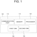
- Fig. 1 is a drawing schematically illustrating a configuration of a computing device performing a method for acquiring location information of an autonomous vehicle by using an attention-driven landmark detection to be used for a route planning in accordance with one example embodiment of the present disclosure.
- the computing device 100 includes a first Convolutional Neural Network(CNN) 130 and possibly a second CNN 140 to be described later. Processes of input/output and computations of the first CNN 130 and the second CNN 140 may be respectively performed by at least one communication part 110 and at least one processor 120. However, detailed communication schematics between the communication part 110 and the processor 120 are omitted in Fig. 1 .
- a memory 115 may have stored various instructions to be described later, and the processor 120 may execute the instructions stored in the memory 115 and may perform processes of the present disclosure by executing the instructions to be disclosed later.
- Such description of the computing device 100 does not exclude an integrated device including any combination of a processor, a memory, a medium, or any other computing components.
- Fig. 2 will be referred to.
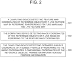
- Fig. 2 is a drawing schematically illustrating a flow of the method for acquiring the location information of the autonomous vehicle by using the attention-driven landmark detection to be used for the route planning in accordance with one example embodiment of the present disclosure.
- the computing device 100 detects each of one or more feature map coordinates on at least one live feature map per each of one or more reference objects by referring to each of one or more reference feature maps corresponding to said each of the reference objects and the live feature map to be explained later. And, at a step of S02, the computing device 100 detects each of image coordinates of each of the reference objects on a live image by referring to each of the feature map coordinates.
- the computing device 100 detects an optimized subject coordinate of the subject vehicle by referring to one or more 3-dimensional coordinates of the reference objects in a real world, the image coordinates, information on parameters of a camera which has acquired the live image, and information on a posture of the subject vehicle. Below, it will be explained more specifically.
- the computing device 100 acquires the live feature map.
- the live feature map has been generated by processing the live image corresponding to a circumstance of the subject vehicle interworking with the computing device 100.
- the live image has been acquired by the camera in the subject vehicle, and has been delivered first to an autonomous driving module which performs an autonomous driving of the subject vehicle.
- the autonomous driving module performs an image segmentation or an object detection by using the live image, in order to perform the autonomous driving based on image processing.
- the live feature has been generated by the autonomous driving module. After it has been generated, it is delivered to the computing device 100. In this case, since the byproduct, i.e., the live feature map, is reused, it may efficient in a usage of computing resources.
- the computing device 100 acquires the reference feature maps corresponding to the reference objects.
- the reference objects are specific objects included in the live image which function as markers to be used for performing a process of localization of the subject vehicle to be explained later.
- the computing device 100 specifies a subject data region whose image has been photographed as the live image, by using (i) an initial subject coordinate, which denotes an approximate location of the subject vehicle, and has been acquired through a Global Positioning System(GPS) in the subject vehicle and (ii) the information on the posture of the subject vehicle acquired through a gyro sensor in the subject vehicle.
- GPS Global Positioning System
- the computing device 100 transmits a query to a High-Density(HD) Map by using information on the specified subject data region, and acquires information on the reference objects and their corresponding reference feature maps, as a reply from the HD Map.
- a High-Density(HD) Map by using information on the specified subject data region, and acquires information on the reference objects and their corresponding reference feature maps, as a reply from the HD Map.
- Fig. 3 will be referred to.
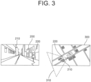
- Fig. 3 is a drawing schematically illustrating an example of reference objects to be used for performing the method for acquiring the location information of the autonomous vehicle by using the attention-driven landmark detection to be used for the route planning in accordance with one example embodiment of the present disclosure.
- a first reference object 210 and a second reference object 220 may be seen in the live image 200.
- the computing device 100 may specify the subject data region 310 on an example map 300 by referring to the initial subject coordinate and the information on the posture of the subject vehicle, to thereby acquire information on the first reference object 210 and the second reference object 220.
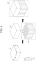
- the computing device 100 detects the feature map coordinates, which represent locations of the reference objects on the live feature map. Specifically, the computing device 100 may generate a specific integrated feature map, to be used for detecting a specific feature map coordinate corresponding to a specific reference object, by channel-wise concatenating (i) a plurality of a specific reference feature map with a size of W 2 ⁇ H 2 ⁇ C 2 , corresponding to the specific reference object and (ii) the live feature map with a size of W 1 ⁇ H 1 ⁇ C 1 in parallel. As an example, both of W 2 and H 2 may be 1. In this case, the specific reference feature map may be channel-wise concatenated W 1 ⁇ H 1 times to the live feature map. To explain such process, Fig. 4 will be referred to.
- Fig. 4 is a drawing schematically illustrating a process of generating a specific integrated feature map to be used for performing the method for acquiring the location information of the autonomous vehicle by using the attention-driven landmark detection to be used for the route planning in accordance with one example embodiment of the present disclosure.
- Fig. 4 it can be seen that the specific integrated feature map 400 has been generated by W 1 ⁇ H 1 times channel-wise concatenating the specific reference feature map 402 to the live feature map 401.
- Fig. 4 corresponds to a case that a size of the specific reference feature map 402 is 1 ⁇ 1 ⁇ C 2 . In other cases that the size thereof is not 1 ⁇ 1 ⁇ C 2 , fewer number of the specific reference feature map 402 will be used for generating the specific integrated feature map.
- the computing device 100 applies at least one first CNN operation to the specific integrated feature map, to thereby find a specific partial live feature map, among partial live feature maps in the live feature map, whose similarity score in relation to the specific reference feature map is larger than a threshold.
- a size of the partial live feature maps may be smaller than the live feature map.
- the size thereof may be 1 ⁇ 1 ⁇ C 1 .
- the specific partial live feature map corresponds to the specific reference object, thus a location of the specific reference object in the live image is estimated by using a relative location of the specific partial live feature map in the live feature map. That is, by using said relative location thereof, the specific feature map coordinate, among the feature map coordinates, which will be precisely processed to detect said location of the reference objects in the live image, can be detected.
- the first CNN 130 which performs said first CNN operation, may include at least one convolutional layer and at least one output layer.
- the output layer may have been built as a Fully-Connected(FC) network.
- the first CNN 130 may have been trained before applying the first CNN operation to the specific integrated feature map.
- the first CNN may have performed (i) a process of applying the first CNN operation to an integrated feature map for training to generate each of one or more estimated similarity scores between each of one or more partial live feature maps for training in the live feature map for training and a reference feature map for training, and (ii) a process of generating a first loss by referring to the estimated similarity scores and their corresponding Ground-Truth(GT) similarity scores, and performing backpropagation by using the first loss.
- GT Ground-Truth
- the feature map coordinates may be detected by using a rule-based algorithm. That is, the relative location of the specific partial live feature map may be found not by using a sort of neural network operation, but by directly calculating the similarity scores between the partial live feature maps and the specific reference feature map.
- the computing device 100 may detect a specific sub-region on the live image corresponding to the specific feature map coordinate.
- the live feature map including the specific partial live feature map, has been generated by down-sampling the live image multiple times through multiple convolutions applied thereto, the specific feature map "coordinate" in the live feature map corresponds to the specific sub-"region" in the live image.
- the computing device 100 may detect a specific sub-region coordinate of the specific reference object representing a location thereof inside the specific sub-region by referring to a specific partial integrated feature map including (i) the specific partial live feature map and (ii) its corresponding specific reference feature map.
- the computing device 100 may instruct the second CNN 140 to apply at least one second CNN operation, whose activation function is a tangent hyperbolic operation, to the specific partial integrated feature map, to thereby detect the specific sub-region coordinate.
- the tangent hyperbolic operation is used as the activation function in order to limit a range of the specific sub-region coordinate, i.e., from -1 to 1. The reason why the range is to be limited will be explained later.
- the second CNN 140 may include at least one convolutional layer and at least one output layer.
- the output layer may have been built as an. FC network.
- the second CNN 140 may have been trained before applying the second CNN operation to the specific partial integrated feature map. That is, the second CNN 140 may have performed (i) a process of applying the second CNN operation to partial integrated feature maps for training to generate estimated sub-region coordinates for training of reference objects for training, and (ii) a process of generating a second loss by referring to the estimated sub-region coordinates and their corresponding Ground-Truth sub-region coordinates, and performing backpropagation by using the second loss.
- the computing device 100 may detect a specific image coordinate among the image coordinates by referring to the specific sub-region coordinate and the specific feature map coordinate.
- Fig. 5 will be referred to.
- Fig. 5 is a drawing schematically illustrating a process of generating information on the specific image coordinate by using the specific sub-region coordinate to be used for performing the method for acquiring the location information of the autonomous vehicle by using the attention-driven landmark detection to be used for the route planning in accordance with one example embodiment of the present disclosure.
- a center coordinate 501 (180,156) of the specific sub-region 500 may be seen.
- Such coordinate may have been calculated by estimating where the specific feature map coordinate (8, 7) on the live feature map with a size of 16 ⁇ 16 will fall in the live image with a size of 384 ⁇ 384. More specifically, each of points in the specific feature map becomes sub-regions with a size of 24 ⁇ 24.
- the center coordinate 501 can be calculated by multiplying 24 to the specific feature map coordinate and then subtracting 12 from the multiplied coordinate.
- the specific sub-region coordinate 502 (0.8, -0.4), which has been calculated as included in said range corresponding to the tangent hyperbolic operation, can be seen.
- the specific image coordinate may be calculated as [180 + 0.8 ⁇ 24,156 + (-0.4) ⁇ 24] ⁇ (200,146), since the specific sub-region coordinate is a vector representing a direction from the center coordinate 501 to the specific reference object in the specific sub-region as seen in the Figure.
- ( x 1 , y 1 ) may denote the specific feature map coordinate
- ( x 2 , y 2 ) may denote the specific sub-region coordinate
- w ⁇ h may denote the size of the specific sub-region.
- the size of the specific sub-region may be determined by referring to a stride used for generating the live feature map, corresponding to a ratio of the size of the live image and that of the live feature map.
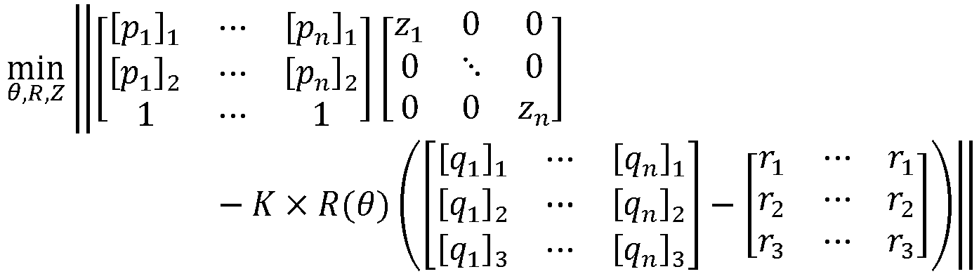
- the computing device 100 uses the image coordinates along with other information to detect the optimized subject coordinate of the subject vehicle in the real world.
- Said other information includes the 3-dimensional coordinates of the reference objects in the real world, the image coordinates, the information on the parameters of the camera which has photographed the live image, and the information on the posture of the subject vehicle.
- the 3-dimensional coordinates may have been acquired along with the reference feature maps from the HD Map.
- [ p j ] k may denote a k-th axis component of a j-th image coordinate of a j-th reference object
- [ q j ] k may denote a k-th axis component of a j-th 3-dimensional coordinate of the j-th reference object
- r k may denote a k-th axis component of the optimized subject coordinate
- z k may denote a k-th diagonal component of a diagonal matrix including arbitrary numbers as its diagonal components.
- K may denote a camera matrix corresponding to the parameters of the camera
- R ( ⁇ ) may denote a rotation matrix corresponding to the posture of the subject vehicle.
- the rotation matrix may be a matrix used for the Rodrigues Rotation Formula, which is a well-known prior art.
- the camera matrix may be a matrix for transforming a coordinate on a 2-dimensional image to a coordinate in a 3-dimensional space, which is well-known in the field of the image processing.
- each of components in one of the 3-dimensional coordinates may denote each of a latitude, a longitude and an altitude of its corresponding reference object.
- the formula may represent an optimization problem, and the computing device 100 may solve the optimization problem, to thereby detect the optimized subject coordinate.
- the optimization problem is solved starting from random initial values, it may not be solved properly. That is, the computing device 100 may only find local minima, or may fail to solve it due to too much requirement for computing resources. In order to prevent such risk, a proper initialization process is necessary. Below, it will be explained more specifically.
- the computing device 100 may perform (i) a process of initializing the rotation matrix by referring to the information on the posture which has been acquired through at least one gyro sensor in the subject vehicle, to thereby generate an initialized rotation matrix, and (ii) a process of initializing a subject coordinate matrix, to be used for acquiring the optimized subject coordinate, by referring to an initial subject coordinate acquired through the GPS in the subject vehicle, to thereby generate an initialized subject coordinate matrix.
- the rotation matrix may be initialized as shown above under an assumption that the information on the posture acquired through the gyro sensor is quite accurate.
- the subject coordinate matrix may be initialized as shown above in order to adjust the location information acquired form the GPS, which may be slightly incorrect.
- the computing device 100 may perform a process of initializing the diagonal matrix by finding an initialized diagonal matrix which minimizes said formula.
- the computing device 100 may finally perform a process of finding an optimized rotation matrix, an optimized subject coordinate matrix and an optimized diagonal matrix which minimize said formula by adjusting values of the initialized rotation matrix, the initialized subject coordinate matrix and the initialized diagonal matrix, to thereby solve the optimization problem, and then to thereby find the optimized subject coordinate by referring to the optimized subject coordinate matrix.
- the optimization problem is directed to a method for adjusting the initial subject coordinate of the subject vehicle based on the GPS by using the image coordinates of the reference objects based on the live image.
- a person in the art may easily understand the method of the present disclosure by referring to above explanation.
- the subject vehicle may become capable of performing the autonomous driving with more accurate location information of itself.
- the embodiments of the present disclosure as explained above can be implemented in a form of executable program command through a variety of computer means recordable to computer readable media.
- the computer readable media may include solely or in combination, program commands, data files, and data structures.
- the program commands recorded to the media may be components specially designed for the present disclosure or may be usable to a skilled human in a field of computer software.
- Computer readable media include magnetic media such as hard disk, floppy disk, and magnetic tape, optical media such as CD-ROM and DVD, magneto-optical media such as floptical disk and hardware devices such as ROM, RAM, and flash memory specially designed to store and carry out program commands.
- Program commands include not only a machine language code made by a complier but also a high level code that can be used by an interpreter etc., which is executed by a computer.
- the aforementioned hardware device can work as more than a software module to perform the action of the present disclosure and they can do the same in the opposite case.
Landscapes
- Engineering & Computer Science (AREA)
- Physics & Mathematics (AREA)
- Theoretical Computer Science (AREA)
- General Physics & Mathematics (AREA)
- Radar, Positioning & Navigation (AREA)
- Remote Sensing (AREA)
- Evolutionary Computation (AREA)
- Artificial Intelligence (AREA)
- Health & Medical Sciences (AREA)
- Software Systems (AREA)
- General Health & Medical Sciences (AREA)
- Computing Systems (AREA)
- Computer Vision & Pattern Recognition (AREA)
- Automation & Control Theory (AREA)
- Multimedia (AREA)
- Computational Linguistics (AREA)
- Biophysics (AREA)
- General Engineering & Computer Science (AREA)
- Molecular Biology (AREA)
- Data Mining & Analysis (AREA)
- Life Sciences & Earth Sciences (AREA)
- Biomedical Technology (AREA)
- Mathematical Physics (AREA)
- Aviation & Aerospace Engineering (AREA)
- Medical Informatics (AREA)
- Databases & Information Systems (AREA)
- Electromagnetism (AREA)
- Image Analysis (AREA)
- Navigation (AREA)
- Business, Economics & Management (AREA)
- Game Theory and Decision Science (AREA)
Claims (11)
- Verfahren zum Detektieren des Standorts eines Subjektfahrzeugs, das zum autonomen Fahren fähig ist, unter Verwendung einer Landmarkendetektion, das die folgenden Schritte umfasst:(a) Erfassen mindestens eines Live-Bildes durch eine Rechenvorrichtung (100) über eine Kamera des Subjektfahrzeugs, wobei das mindestens eine Live-Bild einem Umstand des Subjektfahrzeugs entspricht, der mit der Rechenvorrichtung (100) zusammenwirkt;(b) Liefern des mindestens einen Live-Bildes an ein autonomes Fahrmodul, das ein autonomes Fahren des Subjektfahrzeugs durchführt, wobei das autonome Fahrmodul eine Bildsegmentierung oder eine Objektdetektion unter Verwendung des mindestens einen Live-Bildes durchführt, um das autonome Fahren durchzuführen, wobei das autonome Fahrmodul mindestens eine Live-Merkmalskarte als Nebenprodukt des autonomen Fahrens erzeugt;(c) Erfassen der mindestens einen Live-Merkmalskarte durch die Rechenvorrichtung (100) von dem autonomen Fahrmodul;(d) Übertragen einer Abfrage an eine Hochdichte(HD)-Karte durch die Rechenvorrichtung (100) unter Verwendung einer anfänglichen Subjektkoordinate, die durch ein GPS in dem Subjektfahrzeug erfasst wurde, und der Informationen über eine Haltung des Subjektfahrzeugs;(e) Erfassen, durch die Rechenvorrichtung (100), von Informationen über einen Subjektdatenbereich aus der HD-Karte, einschließlich Referenzmerkmalskarten, die mindestens einem Ort und mindestens einer Haltung des Subjektfahrzeugs entsprechen, von dem die mindestens eine Live-Merkmalskarte erfasst wurde;(f) Detektieren, durch die Rechenvorrichtung (100), jeder der Merkmalskartenkoordinaten auf der mindestens einen Live-Merkmalskarte für jedes von einem oder mehreren Referenzobjekten (210, 220), die in dem Subjektdatenbereich enthalten sind, unter Bezugnahme auf (i) jede der Referenzmerkmalskarten, die jedem der Referenzobjekte entsprechen, und (ii) die mindestens eine Live-Merkmalskarte (S01);(g) Detektieren jeder der Bildkoordinaten jedes der Referenzobjekte auf dem mindestens einen Live-Bild durch die Rechenvorrichtung (100) unter Bezugnahme auf jede der Merkmalskartenkoordinaten (S02); und(h) Detektieren mindestens einer optimierten Subjektkoordinate des Subjektfahrzeugs durch die Rechenvorrichtung (100) unter Bezugnahme auf eine oder mehrere dreidimensionale Koordinaten der Referenzobjekte in einer realen Welt, die Bildkoordinaten, Informationen über Parameter einer Kamera, die das mindestens eine Live-Bild erfasst hat, und Informationen über die Haltung des Subjektfahrzeugs (S03);wobei Schritt (f) ferner umfasst:Erfassen einer spezifischen integrierten Merkmalskarte durch die Rechenvorrichtung (100), die durch kanalweises Verketten (i) einer Vielzahl von einer spezifischen Referenzmerkmalskarte aus den in Schritt (e) erfassten Referenzmerkmalskarten mit einer Größe von W 2 × H 2 × C 2, die einem spezifischen Referenzobjekt aus dem einen oder den mehreren Referenzobjekten (210, 220) entspricht, und (ii) der Live-Merkmalskarte mit einer Größe von W 1 × H 1 × C 1 parallel erzeugt wurde; undAnweisen eines ersten Convolutional Neural Network (CNN), mindestens eine erste CNN-Operation auf die spezifische integrierte Merkmalskarte anzuwenden, um dadurch eine spezifische partielle Live-Merkmalskarte unter partiellen Live-Merkmalskarten in der Live-Merkmalskarte zu finden, deren Ähnlichkeitswert in Bezug auf die spezifische Referenzmerkmalskarte größer als ein Schwellenwert ist, und um dann dadurch eine spezifische Merkmalskartenkoordinate unter den Merkmalskartenkoordinaten unter Bezugnahme auf Informationen über eine relative Position der spezifischen partiellen Live-Merkmalskarte in der Live-Merkmalskarte zu detektieren.
- Verfahren nach Anspruch 1, wobei die Rechenvorrichtung (100) im Schritt (h) zusammen mit den Bildkoordinaten, den dreidimensionalen Koordinaten, den Informationen über die Parameter und den Informationen über die Haltung die mindestens eine optimierte Subjektkoordinate unter Verwendung der folgenden Formel detektiert:
k eine k-te Achsenkomponente einer j-ten Bildkoordinate eines j-ten Referenzobjekts bezeichnet, [qj ]k eine k-te Achsenkomponente einer j-ten 3-dimensionalen Koordinate des j-ten Referenzobjekts bezeichnet, rk eine k-te Achsenkomponente der mindestens einen optimierten Subjektkoordinate bezeichnet, zk eine k-te Diagonalkomponente einer Diagonalmatrix bezeichnet, die beliebige Zahlen als ihre Diagonalkomponenten enthält, K eine Kameramatrix bezeichnet, die den Parametern der Kamera entspricht, R(θ) eine Drehmatrix bezeichnet, die der Haltung des Subjektfahrzeugs entspricht. - Verfahren nach Anspruch 2, wobei die Rechenvorrichtung im Schritt (h) die mindestens eine optimierte Subjektkoordinate durch Lösen eines Optimierungsproblems entsprechend der Formel detektiert,
wobei die Rechenvorrichtung (i) zunächst (i-1) einen Prozess der Initialisierung der Drehmatrix unter Bezugnahme auf die Information über die Haltung, die durch mindestens einen Gyrosensor in dem Subjektfahrzeug erfasst worden ist, durchführt, um dadurch eine initialisierte Drehmatrix zu erzeugen, und (i-2) einen Prozess der Initialisierung einer Subjektkoordinatenmatrix, die für die Erfassung der mindestens einen optimierten Subjektkoordinate zu verwenden ist, unter Bezugnahme auf eine anfängliche Subjektkoordinate, die durch ein Global Positioning System (GPS) in dem Subjektfahrzeug erfasst worden ist, durchführt, um dadurch eine initialisierte Subjektkoordinatenmatrix zu erzeugen, (ii) dann einen Prozess der Initialisierung der Diagonalmatrix durch Auffinden einer initialisierten Diagonalmatrix durchführt, die die Formel unter der Bedingung minimiert, dass die initialisierte Drehmatrix und die initialisierte Subjektkoordinatenmatrix bereitgestellt werden, und (iii) schließlich einen Prozess des Auffindens einer optimierten Drehmatrix durchführt, eine optimierte Subjektkoordinatenmatrix und eine optimierte Diagonalmatrix zu finden, die die Formel minimieren, indem Werte der initialisierten Drehmatrix, der initialisierten Subjektkoordinatenmatrix und der initialisierten Diagonalmatrix eingestellt werden, um dadurch das Optimierungsproblem zu lösen, und um dann dadurch die mindestens eine optimierte Subjektkoordinate unter Bezugnahme auf die optimierte Subjektkoordinatenmatrix zu finden. - Verfahren nach Anspruch 1, wobei der erste CNN trainiert wurde, bevor die erste CNN-Operation auf die spezifische integrierte Merkmalskarte (400) angewendet wurde,
wobei der erste CNN (i) einen Prozess des Anwendens der ersten CNN-Operation auf eine integrierte Merkmalskarte zum Training, um jede von einer oder mehreren geschätzten Ähnlichkeitswerten zwischen jeder von einer oder mehreren partiellen Live-Merkmalskarten zum Training in der mindestens einen Live-Merkmalskarte zum Training und einer Referenzmerkmalskarte zum Training zu erzeugen, und (ii) einen Prozess des Erzeugens eines ersten Verlusts unter Bezugnahme auf die geschätzten Ähnlichkeitswerten und ihre entsprechenden Grundwahrheit (GT)-Ähnlichkeitswerten und des Durchführens von Backpropagation unter Verwendung des ersten Verlusts durchgeführt hat. - Verfahren nach Anspruch 1, wobei im Schritt (g) die Rechenvorrichtung (i) eine spezifische Teilbereichskoordinate eines spezifischen Referenzobjekts auf einem spezifischen Teilbereich, die einer spezifischen Merkmalskartenkoordinate entspricht, in dem mindestens einen Live-Bild unter Bezugnahme auf eine spezifische integrierte Teilmerkmalskarte detektiert, die durch Integrieren (i-1) einer spezifischen partiellen Live-Merkmalskarte, die der spezifischen Merkmalskartenkoordinate entspricht, und (i-2) einer spezifischen Referenzmerkmalskarte (402), die dieser entspricht, erzeugt wurde, und (ii) eine spezifische Bildkoordinate unter den Bildkoordinaten unter Bezugnahme auf die spezifische Teilbereichskoordinate und die spezifische Merkmalskartenkoordinate detektiert.
- Verfahren nach Anspruch 5, bei dem im Schritt (g) die Rechenvorrichtung einen zweiten CNN (140) anweist, mindestens eine zweite CNN-Operation, deren Aktivierungsfunktion eine tangentiale hyperbolische Operation ist, auf die spezifische partiell integrierte Merkmalskarte anzuwenden, um dadurch die spezifische Teilbereichskoordinate zu detektieren.
- Verfahren nach Anspruch 6, wobei der zweite CNN (140) trainiert wurde, bevor die zweite CNN (140)-Operation auf die spezifische partielle integrierte Merkmalskarte angewendet wurde,
wobei der zweite CNN (140) (i) einen Prozess des Anwendens der zweiten CNN-Operation auf partielle integrierte Merkmalskarten zum Training, um geschätzte Teilbereichskoordinaten zum Training von Referenzobjekten zum Training zu erzeugen, die den partiellen integrierten Merkmalskarten zum Training entsprechen, und (ii) einen Prozess des Erzeugens eines zweiten Verlustes unter Bezugnahme auf die geschätzten Teilbereichskoordinaten und ihre entsprechenden Grundwahrheit-Teilbereichskoordinaten und des Durchführens von Backpropagation unter Verwendung des zweiten Verlustes durchgeführt hat. - Vorrichtung (100) zum Detektieren eines Ortes eines Fahrzeugs, das zum autonomen Fahren fähig ist, unter Verwendung einer Landmarkendetektion, umfassend:mindestens einem Speicher (115), der Anweisungen speichert; undmindestens einen Prozessor (120), der konfiguriert ist, die Anweisungen auszuführen, um Prozesse auszuführen:(a) Erfassen mindestens eines Live-Bildes durch eine Kamera des Subjektfahrzeugs, wobei das mindestens eine Live-Bild einem Umstand entspricht, bei dem das Subjektfahrzeug mit der Vorrichtung (100) zusammenarbeitet;(b) Liefern des mindestens einen Live-Bildes an ein autonomes Fahrmodul, das ein autonomes Fahren des Subjektfahrzeugs durchführt, wobei das autonome Fahrmodul eine Bildsegmentierung oder eine Objektdetektion unter Verwendung des mindestens einen Live-Bildes durchführt, um das autonome Fahren durchzuführen, wobei das autonome Fahrmodul mindestens eine Live-Merkmalskarte als Nebenprodukt durch Verarbeiten des mindestens einen Live-Bildes durch Durchführen einer Bildsegmentierung oder einer Objektdetektion unter Verwendung des Live-Bildes erzeugt, während das autonome Fahrmodul ein autonomes Fahren des Subjektfahrzeugs durchführt;(c) Erfassen der mindestens einen Live-Merkmalskarte durch das autonome Fahrmodul;(d) Übertragen einer Abfrage an eine Hochdichte (HD)-Karte unter Verwendung einer anfänglichen Subjektkoordinate, die über ein GPS in dem Subjektfahrzeug erfasst wurde, und von Informationen über die Haltung des Subjektfahrzeugs;(e) Erfassen von Informationen aus der HD-Karte über einen Subjektdatenbereich, einschließlich Referenzmerkmalskarten, die mindestens einem Standort und mindestens einer Haltung des Subjektfahrzeugs entsprechen, von dem die mindestens eine Live-Merkmalskarte erfasst wurde;(f) Detektieren jeder der Merkmalskartenkoordinaten auf der mindestens einen Live-Merkmalskarte für jedes von einem oder mehreren Referenzobjekten (210, 220), die in dem Subjektdatenbereich enthalten sind, unter Bezugnahme auf (i) jede der Referenzmerkmalskarten, die jedem der Referenzobjekte entsprechen, und (ii) die mindestens eine Live-Merkmalskarte;(g) Detektieren jeder der Bildkoordinaten jedes der Referenzobjekte auf dem mindestens einen Live-Bild unter Bezugnahme auf jede der Merkmalskartenkoordinaten; und(h) Detektieren mindestens einer optimierten Subjektkoordinate des Subjektfahrzeugs unter Bezugnahme auf eine oder mehrere dreidimensionale Koordinaten der Referenzobjekte in einer realen Welt, die Bildkoordinaten, Informationen über Parameter einer Kamera, die das mindestens eine Live-Bild erfasst hat, und Informationen über die Haltung des Subjektfahrzeugs;wobei der Prozessor (120) konfiguriert ist, um den Schritt (f) durchzuführen:Erfassen einer spezifischen integrierten Merkmalskarte, die durch kanalweises Verketten (i) einer Vielzahl von einer spezifischen Referenzmerkmalskarte aus den Referenzmerkmalskarten mit einer Größe von W 2 × H 2 × C 2, die einem spezifischen Referenzobjekt aus dem einen oder den mehreren Referenzobjekten (210, 220) entspricht, und (ii) der Live-Merkmalskarte mit einer Größe von W 1 × H 1 × C 1 parallel zueinander erzeugt wurde; undAnweisen eines ersten Convolutional Neural Network (CNN), mindestens eine erste CNN-Operation auf die spezifische integrierte Merkmalskarte anzuwenden, um dadurch eine spezifische partielle Live-Merkmalskarte unter partiellen Live-Merkmalskarten in der Live-Merkmalskarte zu finden, deren Ähnlichkeitswert in Bezug auf die spezifische Referenzmerkmalskarte größer als ein Schwellenwert ist, und um dann dadurch eine spezifische Merkmalskartenkoordinate unter den Merkmalskartenkoordinaten unter Bezugnahme auf Informationen über eine relative Position der spezifischen partiellen Live-Merkmalskarte in der Live-Merkmalskarte zu detektieren.
- Vorrichtung nach Anspruch 8, wobei der Prozessor beim Prozess (h) die mindestens eine optimierte Subjektkoordinate unter Verwendung der Bildkoordinaten, der dreidimensionalen Koordinaten, der Informationen über die Parameter und der Informationen über die Haltung mit Hilfe der folgenden Formel detektiert:

k eine k-te Achsenkomponente einer j-ten Bildkoordinate eines j-ten Referenzobjekts bezeichnet, [qj ]k eine k-te Achsenkomponente einer j-ten 3-dimensionalen Koordinate des j-ten Referenzobjekts bezeichnet, rk eine k-te Achsenkomponente der mindestens einen optimierten Subjektkoordinate bezeichnet, zk eine k-te Diagonalkomponente einer Diagonalmatrix bezeichnet, die beliebige Zahlen als ihre Diagonalkomponenten enthält, K eine Kameramatrix bezeichnet, die den Parametern der Kamera entspricht, R(θ) eine Drehmatrix bezeichnet, die der Haltung des Subjektfahrzeugs entspricht. - Vorrichtung nach Anspruch 9, wobei der Prozessor beim Prozess (h) die mindestens eine optimierte Subjektkoordinate durch Lösen eines Optimierungsproblems entsprechend der Formel detektiert,
wobei der Prozessor (i) zuerst (i-1) einen Prozess des Initialisierens der Drehmatrix unter Bezugnahme auf die Information über die Haltung, die durch mindestens einen Gyrosensor in dem Subjektfahrzeug erfasst wurde, durchführt, um dadurch eine initialisierte Drehmatrix zu erzeugen, und (i-2) einen Prozess des Initialisierens einer Subjektkoordinatenmatrix, die zum Erfassen der mindestens einen optimierten Subjektkoordinate verwendet werden soll, unter Bezugnahme auf eine anfängliche Subjektkoordinate, die durch ein Global Positioning System (GPS) in dem Subjektfahrzeug erfasst wurde, durchführt, um dadurch eine initialisierte Subjektkoordinatenmatrix zu erzeugen, (ii) dann einen Prozess der Initialisierung der Diagonalmatrix durch Auffinden einer initialisierten Diagonalmatrix durchführt, die die Formel unter der Bedingung minimiert, dass die initialisierte Drehmatrix und die initialisierte Subjektkoordinatenmatrix bereitgestellt werden, und (iii) schließlich einen Prozess des Auffindens einer optimierten Drehmatrix durchführt, eine optimierte Subjektkoordinatenmatrix und eine optimierte Diagonalmatrix zu finden, die die Formel minimieren, indem Werte der initialisierten Drehmatrix, der initialisierten Subjektkoordinatenmatrix und der initialisierten Diagonalmatrix eingestellt werden, um dadurch das Optimierungsproblem zu lösen, und um dann dadurch die mindestens eine optimierte Subjektkoordinate unter Bezugnahme auf die optimierte Subjektkoordinatenmatrix zu finden. - Vorrichtung nach Anspruch 8, wobei der erste CNN (130) trainiert wurde, bevor die erste CNN (130)-Operation auf die spezifische integrierte Merkmalskarte (400) angewendet wurde,
wobei der erste CNN (130) (i) einen Prozess des Anwendens der ersten CNN (130)-Operation auf eine integrierte Merkmalskarte zum Training, um jede von einer oder mehreren geschätzten Ähnlichkeitswerten zwischen jeder von einer oder mehreren partiellen Live-Merkmalskarten zum Training in der Live-Merkmalskarte (401) zum Training und einer Referenzmerkmalskarte zum Training zu erzeugen, und (ii) einen Prozess des Erzeugens eines ersten Verlusts unter Bezugnahme auf die geschätzten Ähnlichkeitswerten und ihre entsprechenden Grundwahrheit(GT)-Ähnlichkeitswerten und des Durchführens von Backpropagation unter Verwendung des ersten Verlusts durchgeführt hat.
Applications Claiming Priority (2)
| Application Number | Priority Date | Filing Date | Title |
|---|---|---|---|
| US201962798574P | 2019-01-30 | 2019-01-30 | |
| US16/731,093 US10650548B1 (en) | 2019-01-30 | 2019-12-31 | Method and device for localization of autonomous vehicle for route planning by using attention-driven landmark detection |
Publications (3)
| Publication Number | Publication Date |
|---|---|
| EP3690397A1 EP3690397A1 (de) | 2020-08-05 |
| EP3690397B1 true EP3690397B1 (de) | 2024-06-19 |
| EP3690397C0 EP3690397C0 (de) | 2024-06-19 |
Family
ID=70612951
Family Applications (1)
| Application Number | Title | Priority Date | Filing Date |
|---|---|---|---|
| EP20152584.7A Active EP3690397B1 (de) | 2019-01-30 | 2020-01-20 | Verfahren und vorrichtung zur lokalisierung eines autonomen fahrzeugs zur routenplanung unter verwendung von aufmerksamkeitsgetriebener landmarkenerkennung |
Country Status (5)
| Country | Link |
|---|---|
| US (1) | US10650548B1 (de) |
| EP (1) | EP3690397B1 (de) |
| JP (1) | JP6986769B2 (de) |
| KR (1) | KR102296493B1 (de) |
| CN (1) | CN111736586B (de) |
Families Citing this family (9)
| Publication number | Priority date | Publication date | Assignee | Title |
|---|---|---|---|---|
| CN111693049B (zh) * | 2020-05-20 | 2022-02-11 | 五邑大学 | 一种无人船覆盖投食的动态路径规划方法及设备 |
| DE102020120934A1 (de) | 2020-08-07 | 2022-02-10 | Bayerische Motoren Werke Aktiengesellschaft | Verfahren zum Bereitstellen eines komprimierten neuronalen Netzes zur Multi-Label Multi-Klassen Kategorisierung, Fahrzeugassistenzeinrichtung zur Umgebungskategorisierung und Kraftfahrzeug |
| CN112002112B (zh) * | 2020-08-25 | 2021-11-02 | 中国铁道科学研究院集团有限公司电子计算技术研究所 | 一种高速铁路周界入侵报警系统安防效能评估方法及系统 |
| JP6830561B1 (ja) * | 2020-09-17 | 2021-02-17 | 株式会社スペースリー | 情報処理装置、情報処理方法、情報処理システム、情報処理プログラム |
| KR102289752B1 (ko) * | 2020-10-13 | 2021-08-13 | 주식회사 스페이스소프트인더스트리 | Gps 음영 지역에서 경로 비행을 수행하는 드론 및 그 방법 |
| US12597223B2 (en) * | 2020-11-13 | 2026-04-07 | Nec Corporation | Information processing apparatus, information processing method, and computer program |
| US11669998B2 (en) * | 2021-01-20 | 2023-06-06 | GM Global Technology Operations LLC | Method and system for learning a neural network to determine a pose of a vehicle in an environment |
| US12055412B2 (en) * | 2021-04-19 | 2024-08-06 | Nvidia Corporation | System and methods for updating high definition maps |
| KR20230124815A (ko) * | 2022-02-18 | 2023-08-28 | 현대자동차주식회사 | 자율 주행 제어 장치, 그를 포함하는 차량 시스템, 및 그 방법 |
Citations (2)
| Publication number | Priority date | Publication date | Assignee | Title |
|---|---|---|---|---|
| WO2018138782A1 (ja) * | 2017-01-24 | 2018-08-02 | 富士通株式会社 | 情報処理装置、特徴点抽出プログラムおよび特徴点抽出方法 |
| CN109061703A (zh) * | 2018-06-11 | 2018-12-21 | 百度在线网络技术(北京)有限公司 | 用于定位的方法、装置、设备和计算机可读存储介质 |
Family Cites Families (19)
| Publication number | Priority date | Publication date | Assignee | Title |
|---|---|---|---|---|
| US9290146B2 (en) * | 1992-05-05 | 2016-03-22 | Intelligent Technologies International, Inc. | Optical monitoring of vehicle interiors |
| JP5225542B2 (ja) * | 2004-09-22 | 2013-07-03 | 三菱電機株式会社 | 地図情報生成方法、地図情報生成プログラム及び地図情報収集装置 |
| JP4497133B2 (ja) * | 2006-07-12 | 2010-07-07 | アイシン・エィ・ダブリュ株式会社 | 運転支援方法及び運転支援装置 |
| JP2009180631A (ja) * | 2008-01-31 | 2009-08-13 | Denso It Laboratory Inc | ナビゲーション装置、ナビゲーション方法およびプログラム |
| EP2722646B1 (de) * | 2011-06-14 | 2021-06-09 | Nissan Motor Co., Ltd. | Abstandsmessvorrichtung und vorrichtung zur erzeugung einer umgebungskarte |
| KR101552773B1 (ko) * | 2013-12-10 | 2015-09-11 | 고려대학교 산학협력단 | 인공 표식을 이용한 이동 로봇의 위치 추정 방법 |
| US10395126B2 (en) * | 2015-08-11 | 2019-08-27 | Honda Motor Co., Ltd. | Sign based localization |
| US9446730B1 (en) * | 2015-11-08 | 2016-09-20 | Thunder Power Hong Kong Ltd. | Automatic passenger airbag switch |
| US9727793B2 (en) * | 2015-12-15 | 2017-08-08 | Honda Motor Co., Ltd. | System and method for image based vehicle localization |
| KR101878685B1 (ko) * | 2016-02-12 | 2018-07-16 | 서울과학기술대학교 산학협력단 | 지도 정보를 이용한 차량 측위 시스템 및 방법 |
| JP6331114B2 (ja) * | 2016-03-30 | 2018-05-30 | パナソニックIpマネジメント株式会社 | 位置推定装置、位置推定方法及び制御プログラム |
| KR101804471B1 (ko) * | 2016-06-30 | 2017-12-04 | 주식회사 이누씨 | 영상 분석 방법 및 장치 |
| WO2018031678A1 (en) * | 2016-08-09 | 2018-02-15 | Nauto Global Limited | System and method for precision localization and mapping |
| US20180074494A1 (en) * | 2016-09-13 | 2018-03-15 | Ford Global Technologies, Llc | Passenger tracking systems and methods |
| KR102766548B1 (ko) * | 2016-11-07 | 2025-02-12 | 삼성전자주식회사 | 3차원의 도로 모델을 생성하는 방법 및 장치 |
| KR101955506B1 (ko) * | 2016-12-12 | 2019-03-11 | 주식회사 피엘케이 테크놀로지 | 대향 카메라를 이용한 대형 차량의 측면 안전 보조 장치 및 방법 |
| JP6760114B2 (ja) * | 2017-01-31 | 2020-09-23 | 富士通株式会社 | 情報処理装置、データ管理装置、データ管理システム、方法、及びプログラム |
| JP6589926B2 (ja) * | 2017-04-07 | 2019-10-16 | トヨタ自動車株式会社 | 物体検出装置 |
| US10509947B1 (en) * | 2017-04-11 | 2019-12-17 | Zoox, Inc. | Converting multi-dimensional data for image analysis |
-
2019
- 2019-12-31 US US16/731,093 patent/US10650548B1/en active Active
-
2020
- 2020-01-13 KR KR1020200004516A patent/KR102296493B1/ko active Active
- 2020-01-20 EP EP20152584.7A patent/EP3690397B1/de active Active
- 2020-01-22 JP JP2020008771A patent/JP6986769B2/ja active Active
- 2020-01-23 CN CN202010077028.0A patent/CN111736586B/zh active Active
Patent Citations (4)
| Publication number | Priority date | Publication date | Assignee | Title |
|---|---|---|---|---|
| WO2018138782A1 (ja) * | 2017-01-24 | 2018-08-02 | 富士通株式会社 | 情報処理装置、特徴点抽出プログラムおよび特徴点抽出方法 |
| US20190340456A1 (en) * | 2017-01-24 | 2019-11-07 | Fujitsu Limited | Information processing apparatus, computer-readable recording medium recording feature-point extraction program, and feature-point extraction method |
| CN109061703A (zh) * | 2018-06-11 | 2018-12-21 | 百度在线网络技术(北京)有限公司 | 用于定位的方法、装置、设备和计算机可读存储介质 |
| US20190378296A1 (en) * | 2018-06-11 | 2019-12-12 | Baidu Online Network Technology (Beijing) Co., Ltd. | Method and device for positioning |
Non-Patent Citations (1)
| Title |
|---|
| PINK O ED - SIVIC J ET AL: "Visual map matching and localization using a global feature map", COMPUTER VISION AND PATTERN RECOGNITION WORKSHOPS, 2008. CVPR WORKSHOPS 2008. IEEE COMPUTER SOCIETY CONFERENCE ON, IEEE, PISCATAWAY, NJ, USA, 23 June 2008 (2008-06-23), pages 1 - 7, XP031285691, ISBN: 978-1-4244-2339-2 * |
Also Published As
| Publication number | Publication date |
|---|---|
| EP3690397A1 (de) | 2020-08-05 |
| KR102296493B1 (ko) | 2021-09-02 |
| JP6986769B2 (ja) | 2021-12-22 |
| KR20200094654A (ko) | 2020-08-07 |
| CN111736586B (zh) | 2023-10-03 |
| US10650548B1 (en) | 2020-05-12 |
| JP2020122784A (ja) | 2020-08-13 |
| CN111736586A (zh) | 2020-10-02 |
| EP3690397C0 (de) | 2024-06-19 |
Similar Documents
| Publication | Publication Date | Title |
|---|---|---|
| EP3690397B1 (de) | Verfahren und vorrichtung zur lokalisierung eines autonomen fahrzeugs zur routenplanung unter verwendung von aufmerksamkeitsgetriebener landmarkenerkennung | |
| EP3690727B1 (de) | Lernverfahren und lernvorrichtung für sensorfusion zur integration von informationen, die durch einen zur entfernungsschätzung fähigen radar erfasst werden, und von informationen, die von einer kamera erfasst werden, um dadurch das neuronale netzwerk zur unterstützung von autonomem fahren zu verbessern, sowie testverfahren und testvorrichtung mit verwendung davon | |
| EP3665440B1 (de) | Bildgeoregistrierung zur absoluten navigation unter verwendung von unbestimmter information aus dem navigationssystem an bord | |
| EP3686775B1 (de) | Verfahren zur detektion eines pseudo-3d-begrenzungskastens auf basis von cnn, das in der lage ist, moden gemäss posen von objekten unter verwendung von instanzsegmentierung umzuwandeln | |
| EP3690817B1 (de) | Verfahren zum bereitstellen einer robusten objektabstandsabschätzung auf der basis einer kamera durch präzisere durchführung einer neigungskalibrierung der kamera mit einer fusion von durch die kamera und durch v2v-kommunikation erfassten informationen und vorrichtung damit | |
| EP3690400B1 (de) | Verfahren und vorrichtung zur ego-fahrzeuglokalisierung zur aktualisierung einer hd-karte unter verwendung von v2x-informationsfusion | |
| KR102682524B1 (ko) | 증강 현실에서 가상 객체를 표시하기 위한 측위 방법 및 장치 | |
| EP3690730A2 (de) | Lernverfahren zur unterstützung eines sicheren autonomen fahrens ohne unfallgefahr durch schätzung von bewegungen von umgebenden objekten durch fusion von informationen aus mehreren quellen, lernvorrichtung, prüfverfahren und prüfvorrichtung damit | |
| EP3690846A1 (de) | Lernverfahren und lernvorrichtung zur bestimmung, ob die betriebsart eines fahrzeugs vom manuellen fahrmodus zum autonomen fahrmodus umgeschaltet werden soll, durch durchführung einer fahrwegbasierten verhaltensanalyse der jüngsten fahrroute | |
| US10728461B1 (en) | Method for correcting misalignment of camera by selectively using information generated by itself and information generated by other entities and device using the same | |
| KR102314038B1 (ko) | 인공 신경망 기반으로 광학적 항법을 위하여 특이 영역을 결정하는 방법, 온보드 맵 생성 장치, 및 착륙선의 방향을 결정하는 방법 | |
| EP3686791A1 (de) | Lernverfahren und lernvorrichtung für einen objektdetektor auf cnn-basis zur verwendung für mehrfachkamera- oder rundumsichtüberwachung unter verwendung von bildverkettung und zielobjektzusammenführungsnetzwerk sowie testverfahren und testvorrichtung damit | |
| CN115861860B (zh) | 一种无人机的目标跟踪定位方法和系统 | |
| US10445611B1 (en) | Method for detecting pseudo-3D bounding box to be used for military purpose, smart phone or virtual driving based-on CNN capable of converting modes according to conditions of objects and device using the same | |
| Dumble et al. | Airborne vision-aided navigation using road intersection features | |
| Singh et al. | On lunar on-orbit vision-based navigation: Terrain mapping, feature tracking driven EKF | |
| Kaufmann et al. | Shadow-based matching for precise and robust absolute self-localization during lunar landings | |
| Downes et al. | Wide-area geolocalization with a limited field of view camera in challenging urban environments | |
| CN114830185A (zh) | 借助于神经网络的位置确定 | |
| Das et al. | Taming the north: Multi-camera parallel tracking and mapping in snow-laden environments | |
| Javanmardi et al. | 3D building map reconstruction in dense urban areas by integrating airborne laser point cloud with 2D boundary map | |
| EP4239587B1 (de) | Adaptive merkmalsextraktion zur erkennung von buchstaben und kanten auf fahrzeuglandeflächen | |
| Kramer et al. | Mission Completion–Image Fusion UAS Navigation | |
| CN121409236A (zh) | 一种基于多视图几何的无人机前视导航方法 | |
| CN121280936A (zh) | 一种适用于多环境下的无人机目标定位方法及系统 |
Legal Events
| Date | Code | Title | Description |
|---|---|---|---|
| PUAI | Public reference made under article 153(3) epc to a published international application that has entered the european phase |
Free format text: ORIGINAL CODE: 0009012 |
|
| STAA | Information on the status of an ep patent application or granted ep patent |
Free format text: STATUS: REQUEST FOR EXAMINATION WAS MADE |
|
| 17P | Request for examination filed |
Effective date: 20200120 |
|
| AK | Designated contracting states |
Kind code of ref document: A1 Designated state(s): AL AT BE BG CH CY CZ DE DK EE ES FI FR GB GR HR HU IE IS IT LI LT LU LV MC MK MT NL NO PL PT RO RS SE SI SK SM TR |
|
| AX | Request for extension of the european patent |
Extension state: BA ME |
|
| RBV | Designated contracting states (corrected) |
Designated state(s): AL AT BE BG CH CY CZ DE DK EE ES FI FR GB GR HR HU IE IS IT LI LT LU LV MC MK MT NL NO PL PT RO RS SE SI SK SM TR |
|
| STAA | Information on the status of an ep patent application or granted ep patent |
Free format text: STATUS: EXAMINATION IS IN PROGRESS |
|
| 17Q | First examination report despatched |
Effective date: 20211214 |
|
| RIC1 | Information provided on ipc code assigned before grant |
Ipc: G06N 3/045 20230101ALI20230928BHEP Ipc: G06V 10/764 20220101ALI20230928BHEP Ipc: G06V 20/56 20220101ALI20230928BHEP Ipc: G06V 10/82 20220101ALI20230928BHEP Ipc: G06T 7/73 20170101ALI20230928BHEP Ipc: G06N 3/084 20230101ALI20230928BHEP Ipc: G01C 21/36 20060101ALI20230928BHEP Ipc: G01C 21/28 20060101ALI20230928BHEP Ipc: G06N 3/02 20060101ALI20230928BHEP Ipc: G01C 21/20 20060101AFI20230928BHEP |
|
| GRAP | Despatch of communication of intention to grant a patent |
Free format text: ORIGINAL CODE: EPIDOSNIGR1 |
|
| STAA | Information on the status of an ep patent application or granted ep patent |
Free format text: STATUS: GRANT OF PATENT IS INTENDED |
|
| INTG | Intention to grant announced |
Effective date: 20240124 |
|
| GRAS | Grant fee paid |
Free format text: ORIGINAL CODE: EPIDOSNIGR3 |
|
| GRAA | (expected) grant |
Free format text: ORIGINAL CODE: 0009210 |
|
| STAA | Information on the status of an ep patent application or granted ep patent |
Free format text: STATUS: THE PATENT HAS BEEN GRANTED |
|
| AK | Designated contracting states |
Kind code of ref document: B1 Designated state(s): AL AT BE BG CH CY CZ DE DK EE ES FI FR GB GR HR HU IE IS IT LI LT LU LV MC MK MT NL NO PL PT RO RS SE SI SK SM TR |
|
| REG | Reference to a national code |
Ref country code: GB Ref legal event code: FG4D |
|
| REG | Reference to a national code |
Ref country code: CH Ref legal event code: EP |
|
| REG | Reference to a national code |
Ref country code: DE Ref legal event code: R096 Ref document number: 602020032513 Country of ref document: DE |
|
| U01 | Request for unitary effect filed |
Effective date: 20240715 |
|
| U07 | Unitary effect registered |
Designated state(s): AT BE BG DE DK EE FI FR IT LT LU LV MT NL PT SE SI Effective date: 20240723 |
|
| PG25 | Lapsed in a contracting state [announced via postgrant information from national office to epo] |
Ref country code: HR Free format text: LAPSE BECAUSE OF FAILURE TO SUBMIT A TRANSLATION OF THE DESCRIPTION OR TO PAY THE FEE WITHIN THE PRESCRIBED TIME-LIMIT Effective date: 20240619 |
|
| PG25 | Lapsed in a contracting state [announced via postgrant information from national office to epo] |
Ref country code: GR Free format text: LAPSE BECAUSE OF FAILURE TO SUBMIT A TRANSLATION OF THE DESCRIPTION OR TO PAY THE FEE WITHIN THE PRESCRIBED TIME-LIMIT Effective date: 20240920 |
|
| PG25 | Lapsed in a contracting state [announced via postgrant information from national office to epo] |
Ref country code: NO Free format text: LAPSE BECAUSE OF FAILURE TO SUBMIT A TRANSLATION OF THE DESCRIPTION OR TO PAY THE FEE WITHIN THE PRESCRIBED TIME-LIMIT Effective date: 20240919 Ref country code: HR Free format text: LAPSE BECAUSE OF FAILURE TO SUBMIT A TRANSLATION OF THE DESCRIPTION OR TO PAY THE FEE WITHIN THE PRESCRIBED TIME-LIMIT Effective date: 20240619 Ref country code: GR Free format text: LAPSE BECAUSE OF FAILURE TO SUBMIT A TRANSLATION OF THE DESCRIPTION OR TO PAY THE FEE WITHIN THE PRESCRIBED TIME-LIMIT Effective date: 20240920 Ref country code: RS Free format text: LAPSE BECAUSE OF FAILURE TO SUBMIT A TRANSLATION OF THE DESCRIPTION OR TO PAY THE FEE WITHIN THE PRESCRIBED TIME-LIMIT Effective date: 20240919 |
|
| PG25 | Lapsed in a contracting state [announced via postgrant information from national office to epo] |
Ref country code: PL Free format text: LAPSE BECAUSE OF FAILURE TO SUBMIT A TRANSLATION OF THE DESCRIPTION OR TO PAY THE FEE WITHIN THE PRESCRIBED TIME-LIMIT Effective date: 20240619 |
|
| PG25 | Lapsed in a contracting state [announced via postgrant information from national office to epo] |
Ref country code: IS Free format text: LAPSE BECAUSE OF FAILURE TO SUBMIT A TRANSLATION OF THE DESCRIPTION OR TO PAY THE FEE WITHIN THE PRESCRIBED TIME-LIMIT Effective date: 20241019 |
|
| PG25 | Lapsed in a contracting state [announced via postgrant information from national office to epo] |
Ref country code: CZ Free format text: LAPSE BECAUSE OF FAILURE TO SUBMIT A TRANSLATION OF THE DESCRIPTION OR TO PAY THE FEE WITHIN THE PRESCRIBED TIME-LIMIT Effective date: 20240619 |
|
| PG25 | Lapsed in a contracting state [announced via postgrant information from national office to epo] |
Ref country code: RO Free format text: LAPSE BECAUSE OF FAILURE TO SUBMIT A TRANSLATION OF THE DESCRIPTION OR TO PAY THE FEE WITHIN THE PRESCRIBED TIME-LIMIT Effective date: 20240619 Ref country code: SK Free format text: LAPSE BECAUSE OF FAILURE TO SUBMIT A TRANSLATION OF THE DESCRIPTION OR TO PAY THE FEE WITHIN THE PRESCRIBED TIME-LIMIT Effective date: 20240619 |
|
| PG25 | Lapsed in a contracting state [announced via postgrant information from national office to epo] |
Ref country code: ES Free format text: LAPSE BECAUSE OF FAILURE TO SUBMIT A TRANSLATION OF THE DESCRIPTION OR TO PAY THE FEE WITHIN THE PRESCRIBED TIME-LIMIT Effective date: 20240619 Ref country code: SM Free format text: LAPSE BECAUSE OF FAILURE TO SUBMIT A TRANSLATION OF THE DESCRIPTION OR TO PAY THE FEE WITHIN THE PRESCRIBED TIME-LIMIT Effective date: 20240619 |
|
| PG25 | Lapsed in a contracting state [announced via postgrant information from national office to epo] |
Ref country code: SM Free format text: LAPSE BECAUSE OF FAILURE TO SUBMIT A TRANSLATION OF THE DESCRIPTION OR TO PAY THE FEE WITHIN THE PRESCRIBED TIME-LIMIT Effective date: 20240619 Ref country code: SK Free format text: LAPSE BECAUSE OF FAILURE TO SUBMIT A TRANSLATION OF THE DESCRIPTION OR TO PAY THE FEE WITHIN THE PRESCRIBED TIME-LIMIT Effective date: 20240619 Ref country code: RO Free format text: LAPSE BECAUSE OF FAILURE TO SUBMIT A TRANSLATION OF THE DESCRIPTION OR TO PAY THE FEE WITHIN THE PRESCRIBED TIME-LIMIT Effective date: 20240619 Ref country code: PL Free format text: LAPSE BECAUSE OF FAILURE TO SUBMIT A TRANSLATION OF THE DESCRIPTION OR TO PAY THE FEE WITHIN THE PRESCRIBED TIME-LIMIT Effective date: 20240619 Ref country code: IS Free format text: LAPSE BECAUSE OF FAILURE TO SUBMIT A TRANSLATION OF THE DESCRIPTION OR TO PAY THE FEE WITHIN THE PRESCRIBED TIME-LIMIT Effective date: 20241019 Ref country code: ES Free format text: LAPSE BECAUSE OF FAILURE TO SUBMIT A TRANSLATION OF THE DESCRIPTION OR TO PAY THE FEE WITHIN THE PRESCRIBED TIME-LIMIT Effective date: 20240619 Ref country code: CZ Free format text: LAPSE BECAUSE OF FAILURE TO SUBMIT A TRANSLATION OF THE DESCRIPTION OR TO PAY THE FEE WITHIN THE PRESCRIBED TIME-LIMIT Effective date: 20240619 |
|
| U20 | Renewal fee for the european patent with unitary effect paid |
Year of fee payment: 6 Effective date: 20250121 |
|
| PLBE | No opposition filed within time limit |
Free format text: ORIGINAL CODE: 0009261 |
|
| STAA | Information on the status of an ep patent application or granted ep patent |
Free format text: STATUS: NO OPPOSITION FILED WITHIN TIME LIMIT |
|
| 26N | No opposition filed |
Effective date: 20250320 |
|
| REG | Reference to a national code |
Ref country code: CH Ref legal event code: PL |
|
| PG25 | Lapsed in a contracting state [announced via postgrant information from national office to epo] |
Ref country code: MC Free format text: LAPSE BECAUSE OF FAILURE TO SUBMIT A TRANSLATION OF THE DESCRIPTION OR TO PAY THE FEE WITHIN THE PRESCRIBED TIME-LIMIT Effective date: 20240619 |
|
| GBPC | Gb: european patent ceased through non-payment of renewal fee |
Effective date: 20250120 |
|
| PG25 | Lapsed in a contracting state [announced via postgrant information from national office to epo] |
Ref country code: GB Free format text: LAPSE BECAUSE OF NON-PAYMENT OF DUE FEES Effective date: 20250120 |
|
| PG25 | Lapsed in a contracting state [announced via postgrant information from national office to epo] |
Ref country code: CH Free format text: LAPSE BECAUSE OF NON-PAYMENT OF DUE FEES Effective date: 20250131 |
|
| PG25 | Lapsed in a contracting state [announced via postgrant information from national office to epo] |
Ref country code: IE Free format text: LAPSE BECAUSE OF NON-PAYMENT OF DUE FEES Effective date: 20250120 |
|
| U20 | Renewal fee for the european patent with unitary effect paid |
Year of fee payment: 7 Effective date: 20260122 |