EP3690376A1 - Heat exchanger - Google Patents
Heat exchanger Download PDFInfo
- Publication number
- EP3690376A1 EP3690376A1 EP19305132.3A EP19305132A EP3690376A1 EP 3690376 A1 EP3690376 A1 EP 3690376A1 EP 19305132 A EP19305132 A EP 19305132A EP 3690376 A1 EP3690376 A1 EP 3690376A1
- Authority
- EP
- European Patent Office
- Prior art keywords
- moving element
- refrigerant flow
- diffuser
- openings
- refrigerant
- Prior art date
- Legal status (The legal status is an assumption and is not a legal conclusion. Google has not performed a legal analysis and makes no representation as to the accuracy of the status listed.)
- Granted
Links
- 239000003507 refrigerant Substances 0.000 claims abstract description 80
- 238000011144 upstream manufacturing Methods 0.000 claims abstract description 4
- 230000005484 gravity Effects 0.000 claims description 9
- 238000009826 distribution Methods 0.000 description 4
- 230000000694 effects Effects 0.000 description 3
- 230000007423 decrease Effects 0.000 description 2
- 230000001010 compromised effect Effects 0.000 description 1
- 230000001939 inductive effect Effects 0.000 description 1
- 239000007791 liquid phase Substances 0.000 description 1
- 239000012071 phase Substances 0.000 description 1
- 238000005057 refrigeration Methods 0.000 description 1
- 238000000926 separation method Methods 0.000 description 1
- 239000007787 solid Substances 0.000 description 1
- XLYOFNOQVPJJNP-UHFFFAOYSA-N water Substances O XLYOFNOQVPJJNP-UHFFFAOYSA-N 0.000 description 1
Images


Classifications
-
- F—MECHANICAL ENGINEERING; LIGHTING; HEATING; WEAPONS; BLASTING
- F28—HEAT EXCHANGE IN GENERAL
- F28D—HEAT-EXCHANGE APPARATUS, NOT PROVIDED FOR IN ANOTHER SUBCLASS, IN WHICH THE HEAT-EXCHANGE MEDIA DO NOT COME INTO DIRECT CONTACT
- F28D21/00—Heat-exchange apparatus not covered by any of the groups F28D1/00 - F28D20/00
- F28D21/0017—Flooded core heat exchangers
-
- F—MECHANICAL ENGINEERING; LIGHTING; HEATING; WEAPONS; BLASTING
- F25—REFRIGERATION OR COOLING; COMBINED HEATING AND REFRIGERATION SYSTEMS; HEAT PUMP SYSTEMS; MANUFACTURE OR STORAGE OF ICE; LIQUEFACTION SOLIDIFICATION OF GASES
- F25B—REFRIGERATION MACHINES, PLANTS OR SYSTEMS; COMBINED HEATING AND REFRIGERATION SYSTEMS; HEAT PUMP SYSTEMS
- F25B39/00—Evaporators; Condensers
- F25B39/02—Evaporators
-
- F—MECHANICAL ENGINEERING; LIGHTING; HEATING; WEAPONS; BLASTING
- F28—HEAT EXCHANGE IN GENERAL
- F28D—HEAT-EXCHANGE APPARATUS, NOT PROVIDED FOR IN ANOTHER SUBCLASS, IN WHICH THE HEAT-EXCHANGE MEDIA DO NOT COME INTO DIRECT CONTACT
- F28D7/00—Heat-exchange apparatus having stationary tubular conduit assemblies for both heat-exchange media, the media being in contact with different sides of a conduit wall
- F28D7/16—Heat-exchange apparatus having stationary tubular conduit assemblies for both heat-exchange media, the media being in contact with different sides of a conduit wall the conduits being arranged in parallel spaced relation
-
- F—MECHANICAL ENGINEERING; LIGHTING; HEATING; WEAPONS; BLASTING
- F28—HEAT EXCHANGE IN GENERAL
- F28F—DETAILS OF HEAT-EXCHANGE AND HEAT-TRANSFER APPARATUS, OF GENERAL APPLICATION
- F28F9/00—Casings; Header boxes; Auxiliary supports for elements; Auxiliary members within casings
-
- F—MECHANICAL ENGINEERING; LIGHTING; HEATING; WEAPONS; BLASTING
- F28—HEAT EXCHANGE IN GENERAL
- F28F—DETAILS OF HEAT-EXCHANGE AND HEAT-TRANSFER APPARATUS, OF GENERAL APPLICATION
- F28F9/00—Casings; Header boxes; Auxiliary supports for elements; Auxiliary members within casings
- F28F9/02—Header boxes; End plates
- F28F9/026—Header boxes; End plates with static flow control means, e.g. with means for uniformly distributing heat exchange media into conduits
- F28F9/0265—Header boxes; End plates with static flow control means, e.g. with means for uniformly distributing heat exchange media into conduits by using guiding means or impingement means inside the header box
-
- F—MECHANICAL ENGINEERING; LIGHTING; HEATING; WEAPONS; BLASTING
- F25—REFRIGERATION OR COOLING; COMBINED HEATING AND REFRIGERATION SYSTEMS; HEAT PUMP SYSTEMS; MANUFACTURE OR STORAGE OF ICE; LIQUEFACTION SOLIDIFICATION OF GASES
- F25B—REFRIGERATION MACHINES, PLANTS OR SYSTEMS; COMBINED HEATING AND REFRIGERATION SYSTEMS; HEAT PUMP SYSTEMS
- F25B2339/00—Details of evaporators; Details of condensers
- F25B2339/02—Details of evaporators
- F25B2339/024—Evaporators with refrigerant in a vessel in which is situated a heat exchanger
- F25B2339/0242—Evaporators with refrigerant in a vessel in which is situated a heat exchanger having tubular elements
-
- F—MECHANICAL ENGINEERING; LIGHTING; HEATING; WEAPONS; BLASTING
- F25—REFRIGERATION OR COOLING; COMBINED HEATING AND REFRIGERATION SYSTEMS; HEAT PUMP SYSTEMS; MANUFACTURE OR STORAGE OF ICE; LIQUEFACTION SOLIDIFICATION OF GASES
- F25B—REFRIGERATION MACHINES, PLANTS OR SYSTEMS; COMBINED HEATING AND REFRIGERATION SYSTEMS; HEAT PUMP SYSTEMS
- F25B39/00—Evaporators; Condensers
- F25B39/02—Evaporators
- F25B39/028—Evaporators having distributing means
-
- F—MECHANICAL ENGINEERING; LIGHTING; HEATING; WEAPONS; BLASTING
- F28—HEAT EXCHANGE IN GENERAL
- F28D—HEAT-EXCHANGE APPARATUS, NOT PROVIDED FOR IN ANOTHER SUBCLASS, IN WHICH THE HEAT-EXCHANGE MEDIA DO NOT COME INTO DIRECT CONTACT
- F28D21/00—Heat-exchange apparatus not covered by any of the groups F28D1/00 - F28D20/00
- F28D2021/0019—Other heat exchangers for particular applications; Heat exchange systems not otherwise provided for
- F28D2021/0068—Other heat exchangers for particular applications; Heat exchange systems not otherwise provided for for refrigerant cycles
- F28D2021/0071—Evaporators
Landscapes
- Engineering & Computer Science (AREA)
- Physics & Mathematics (AREA)
- Thermal Sciences (AREA)
- Mechanical Engineering (AREA)
- General Engineering & Computer Science (AREA)
- Heat-Exchange Devices With Radiators And Conduit Assemblies (AREA)
Abstract
Description
- The present invention concerns a heat exchanger such as a flooded evaporator.
- Flooded evaporators for air treatment units (for example, chillers) comprise a shell in which a refrigerant gas circulates and which liquid phases are mixed. Refrigerant diffusers are used in flooded evaporators to evenly distribute refrigerant flow along the length of the shell.
- Two phase refrigerant flow enters into the diffuser which in general has an elongated geometry with openings distributed along the length of the diffuser. The general aim of the diffuser is to facilitate an even distribution of the refrigerant by selecting openings geometry which compensate the variation of pressure differential between diffuser and evaporator shell which occurs along the length of the diffuser (from an entering section to the axial ends sections). In the entering section (directly downstream the inlet pipe, where the flow of refrigerant is close to its maximal value), which presents higher resistance (higher overall velocity and pressure) to preserve constant flow, smaller section openings are generally provided. Towards the axial ends of the diffuser (small flow and low pressure), openings are larger to preserve equivalent flow.
- When the geometry of the diffuser is selected to optimize full load operation (maximal refrigerant flow), the geometry is not optimal for part load (lower refrigerant flow) operation. In a case of part load, overall refrigerant flow is low and resulting pressure difference between diffuser and shell decreases drastically which result in high variations of refrigerant flows in each individual opening. Flow distribution is therefore compromised, as it results in high flow in end section of diffuser, and low flow in medium section and also results in flow separation. This uneven distribution can also be observed in a case of operating conditions which are significantly different from reference conditions in which the diffuser has been optimized. For example, varying refrigerant pressures may result in varying refrigerant densities and subsequent varying refrigerant velocities departing from the usual refrigerant velocities the flooded evaporator is designed to handle.
- The aim of the invention is to provide a new heat exchanger in which the diffuser is better adapted to part load or operation conditions that do not correspond to the nominal conditions for which the heat exchanger has been designed.
- To this end, the invention concerns a heat exchanger, such as a flooded evaporator, comprising a shell extending along a longitudinal axis, an inlet pipe and an outlet pipe, through which respectively enters and exits a refrigerant flow, and a bundle of pipes crossing the shell along the longitudinal axis, and comprising a refrigerant flow diffuser provided inside the shell downstream the inlet pipe, the refrigerant flow diffuser extending along the longitudinal axis and comprising openings through which the refrigerant flows. The refrigerant flow diffuser comprises a moving element and a stationary element, the moving element being movable with respect to the stationary element under action of a pressure force exerted by the refrigerant flow so that the refrigerant flow going through the openings is adjusted and a differential refrigerant pressure between refrigerant pressure downstream and upstream the refrigerant flow diffuser is kept constant.
- Thanks to the invention, the geometry of the openings of the diffuser is constantly adapted under action of the refrigerant pressure force to maintain constant the pressure difference between the inside of the diffuser and the shell.
- According to further aspects of the invention which are advantageous but not compulsory, such a heat exchanger may include one or several of the following features:
- The moving element is movable along a vertical direction, and the pressure force exerts upwards against a gravity force exerted on the moving element.
- In absence of refrigerant flow through the diffuser, the moving element is laid on the stationary element closing the openings.
- The openings are provided on the moving element and the stationary element in a shifted arrangement so that when the moving element is laid on the stationary element, the openings of the stationary element are closed by the moving element while the openings of the moving element are closed by the stationary element.
- The refrigerant flow diffuser has an angled shape, each of the moving element and the stationary element being formed by two angled plates.
- The diffuser comprises guides for the movement of the moving element.
- The guides comprise rectilinear slots, and the moving element comprises pins inserted in the rectilinear slots in a sliding manner.
- The invention will now be explained as an illustrative example with regard to the annexed figures, in which:
-
figure 1 is a transversal sectional view of a heat exchanger according to the invention in the form of a flooded evaporator; -
figure 2 is a sectional view along plane II-II of a refrigerant diffuser of the flooded evaporator offigure 1 ; -
figure 3 is a transversal sectional view at a larger scale of the diffuser, with forces exerted on a moving part of the diffuser being represented; -
figure 4 is a transversal sectional view of a lateral portion of the diffuser, in a closed configuration; -
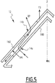
figure 5 is a transversal sectional view similar tofigure 4 , in a half-open configuration; -
figure 6 is a transversal sectional view similar tofigure 4 , in an open configuration; -
figure 7 is an exploded transversal sectional view of another embodiment of the diffuser; -
figures 8 and9 are transversal sectional views of the diffuser offigure 7 in closed and open configurations; -
figure 10 is a view similar tofigure 2 , of another embodiment of the heat exchanger. -
Figure 1 show a heat exchanger in the form of a floodedevaporator 2, for example for the refrigeration circuit of a chiller. The floodedevaporator 2 comprises ashell 4 extending along a longitudinal axis X. Theshell 4 has a substantial cylindrical shape centered on an axis parallel to the longitudinal X. - The flooded
evaporator 2 comprises aninlet pipe 6 and an outlet or suction pipe 8, through which respectively enters in theshell 4 and exits from the shell 4 a refrigerant flow along arrows F1 and F2 infigure 1 . The floodedevaporator 2 also comprises a bundle ofpipes 10 crossing theshell 4 along the longitudinal axis X. The bundle ofpipes 10 is provided for the circulation in theshell 4 of a water flow to be cooled. - On
figure 1 ,pipes 10 are represented filling most of the upper half ofshell 4. However, other distributions of thepipes 10 are possible. In particular pipes, 10 can be absent from the upper quarter ofshell 4. - Non represented
pipes 10 are also be provided in the lower half ofshell 4. - The flooded
evaporator 2 comprises arefrigerant flow diffuser 12 provided inside theshell 4 downstream theinlet pipe 6, therefrigerant flow diffuser 12 extending along the longitudinal axis X and comprisingopenings diffuser 12. The aim of thediffuser 12 is to evenly distribute the refrigerant flow along the length of theshell 4, to obtain a constant refrigerant pressure along the longitudinal axis X. - As shown on
figure 3 , to overcome the above-mentioned issues related to part load or degraded working conditions, therefrigerant flow diffuser 12 comprises a movingelement 16 and astationary element 18, the movingelement 16 being movable with respect to thestationary element 18 under action of a pressure force FP exerted by the refrigerant flow F1, so that the flow of refrigerant F1 going through theopenings - At the outlet of the
openings 14a of thestationary element 18, the refrigerant can go up through theopenings 14b of themoveable element 16, then towards theshell 4. Alternatively, at the outlet of theopenings 14a of thestationary element 18, the refrigerant can go below themoveable element 16, directly towards theshell 4 - In the present example, the
moving element 16 is movable along a vertical direction Z, which is perpendicular to the longitudinal axis X, and the pressure force FP exerts upwards against the gravity effect, which exerts a force FG on themoving element 16. - As represented on
figure 3 , therefrigerant flow diffuser 12 may have an angled shape. The movingelement 16 is formed by twoangled plates stationary element 18 is formed by twoangled plates plates plates stationary element 18 bears theopenings 14a, while themoving element 16 bears theopenings 14b. Theopenings diffuser 12. - The
openings moving element 16 is laid on thestationary element 18, theopenings 14a are closed by themoving element 16 while theopenings 14b are closed by thestationary element 18. As theopenings holes 14a faces solid areas of theplates 161 and 162 and exerts a pressure force. - As shown on
figure 3 , the refrigerant pressure flowing through theopenings 14a exerts a force FP1 on theplate 160 of the movingelement 16, on the left side of thediffuser 12, while the refrigerant pressure exerts a force FP2 on theplate 162 on the right side of thediffuser 12. The forces FP1 and FP2 are exerted on active surfaces AF of theplates plates openings 14a. The active surfaces AF have the shape of theopenings 14a. The plurality ofopenings 14a delimits a total active surface of themoving element 16 that corresponds to the sum of the surfaces of the active surfaces AF. In other words, the total active surface of the movingelement 16 equals the added surfaces of theopenings 14a of thestationary element 18. - The active surfaces AF being angled with respect to the vertical direction Z, the pressure forces FP1 and FP2 are angled, and the resulting force FP, formed by the sum of forces FP1 and FP2 projected in the direction Z, counteracts the gravity force FG.
- When no refrigerant enters the
diffuser 12, no pressure is exerted on the movingelement 16, which then rests on thestationary element 18 under the effect of gravity. Thediffuser 12 is therefore closed, as shown on the detail of theplates figure 4 . - When refrigerant enters the
diffuser 12 and pressure P1 starts to build, the pressure force FP increases and begins to counter act the gravity force FG, until the pressure force FP equals and overcomes the gravity force FG. The movingelement 16 is therefore lifted along arrow F3, opening thediffuser 12 allowing refrigerant to flow along a refrigerant path RP through theopenings figure 5 ). The movingelement 16 is lifted until the pressure force FP and the gravity force FG are in balance, setting the pressure difference between P1 and P2. - If the pressure P1 increases further, to maintain the pressure difference constant, the moving
element 16 is lifted further until the balance of forces is obtained again. This increases the distance between thestationary element 18 and the movingelement 16, thus enlarging the refrigerant path RP, to allow more refrigerant to flow between thestationary element 18 and the moving element 16 (figure 6 ),. The refrigerant pressure therefore acts on the geometry of the refrigerant path RP through thediffuser 12, the increase of the pressure inducing enlargement of the geometry of the refrigerant path RP through theopenings figure 5 . - If pressure P1 decreases, the moving
element 16 will stay in place until the gravity force FG is above the pressure force FP. The movingelement 16 is then lowered until the pressure difference and the balance of forces are obtained again, or until thediffuser 12 closes, if the pressure P1 has become too low. - For example, the pressure differential between P1 and P2 may be 100kPa. The weight of the moving
element 16 may be chosen as a function of the surface of theopenings 14a in order to obtain a predetermined pressure differential. - At the outlet of the
openings 14a of thestationary element 18, the refrigerant can go up through theopenings 14b of themoveable element 16, then towards theshell 4, as shown by arrows RP on thefigures 5 and6 . In addition, at the outlet of theopenings 14a of thestationary element 18, the refrigerant can go below themoveable element 16, directly towards theshell 4, as shown by the arrows oriented towards the left lower corner offigures 5 and6 . - According to an embodiment shown in
figures 7 to 9 , thediffuser 12 may comprise guiding elements for the movement of the movingelement 16. The guiding elements may compriseflanges 20 located at the axial ends of thediffuser 12, and provided withrectilinear slots 22. The movingelement 16 may comprisepins 24 inserted in therectilinear slots 22 so that the pins slide in therectilinear slots 22 to allow efficient guidance of the movingelement 16 along its movement direction Z. Thestationary element 18 may comprisesimilar pins 24 inserted in a fixed configuration in the rectilinear slots to make integral theflanges 20 and thestationary element 18. - According to an embodiment represented on
figure 10 , theopenings diffuser 12, from acentral area 26 of thediffuser 12 towards axial ends 28 of thediffuser 12. In thecentral area 26, theopenings central area 26, theopenings - The
openings figure 3 , or a square or rectangular shape, as shown onfigure 10 . - The
openings stationary element 18 and/or on the movingelement 16, are not necessarily circular. They can have another shape. - The guiding means are not necessarily the ones shown as an example with
references element 16 is efficiently guided with respect to thestationary element 18. - Conical reliefs, or reliefs with any other shape, can be soldered, or fixed in any other way, to the moving
element 16, in register with theopenings 14a of thestationary element 18. This allows improved control of the flow section between the twoelements - According to non-shown embodiment, the
diffuser 12 may have a shape different from the angled shape represented. In particular, thediffuser 12 is not necessarily V shaped. For example, half-cylindrical, flat or square shapes may be implemented while providing the same effects. - According to another non-shown embodiment, the
diffuser 12 may comprise openings provided on thestationary element 18 only. In other words, the movingelement 16 can be without openings. The refrigerant flows from theopenings 14a of thestationary element 18, change direction on themovable element 16 and flows to theshell 4 below the moving element.
Claims (7)
- Heat exchanger (2), such as a flooded evaporator, comprising a shell (4) extending along a longitudinal axis (X), an inlet pipe (6) and an outlet pipe (8), through which respectively enters (F1) and exits (F2) a refrigerant flow, and a bundle of pipes (10) crossing the shell (4) along the longitudinal axis (X), and comprising a refrigerant flow diffuser (12) provided inside the shell (4) downstream the inlet pipe (6), the refrigerant flow diffuser (12) extending along the longitudinal axis (X) and comprising openings (14a, 14b) through which the refrigerant flows, wherein the refrigerant flow diffuser (12) comprises a moving element (16) and a stationary element (18), the moving element (16) being movable with respect to the stationary element (18) under action of a pressure force (FP) exerted by the refrigerant flow so that the refrigerant flow going through the openings (14a, 14b) is adjusted and a differential refrigerant pressure between refrigerant pressure downstream (P2) and upstream (P1) the refrigerant flow diffuser (12) is kept constant.
- Heat exchanger according to claim 1, wherein the moving element (16) is movable along a vertical direction (Z), and the pressure force (FP) exerts upwards against a gravity force (FP) exerted on the moving element (16).
- Heat exchanger according to claim 2, wherein in absence of refrigerant flow through the diffuser (12), the moving element (16) is laid on the stationary element (18) closing the openings (14a, 14b).
- Heat exchanger according to claim 3, wherein the openings (14a, 14b) are provided on the moving element (16) and the stationary element (18) in a shifted arrangement so that when the moving element (16) is laid on the stationary element (18), the openings (14a) of the stationary element (18) are closed by the moving element (16) while the openings (14b) of the moving element (16) are closed by the stationary element (18).
- Heat exchanger according to any preceding claim, wherein the refrigerant flow diffuser (12) has an angled shape, each of the moving element (16) and the stationary element (18) being formed by two angled plates (160, 162, 180, 182).
- Heat exchanger according to any preceding claim, wherein the diffuser (12) comprises guides (20) for the movement of the moving element (16).
- Heat exchanger according to claim 6, wherein the guides (20) comprise rectilinear slots (22), and wherein the moving element (16) comprises pins (24) inserted in the rectilinear slots (22) in a sliding manner.
Priority Applications (4)
| Application Number | Priority Date | Filing Date | Title |
|---|---|---|---|
| EP19305132.3A EP3690376B1 (en) | 2019-02-04 | 2019-02-04 | Heat exchanger |
| ES19305132T ES2884624T3 (en) | 2019-02-04 | 2019-02-04 | Heat exchanger |
| US16/778,894 US11408653B2 (en) | 2019-02-04 | 2020-01-31 | Heat exchanger |
| CN202010078545.XA CN111520935B (en) | 2019-02-04 | 2020-02-03 | heat exchanger |
Applications Claiming Priority (1)
| Application Number | Priority Date | Filing Date | Title |
|---|---|---|---|
| EP19305132.3A EP3690376B1 (en) | 2019-02-04 | 2019-02-04 | Heat exchanger |
Publications (2)
| Publication Number | Publication Date |
|---|---|
| EP3690376A1 true EP3690376A1 (en) | 2020-08-05 |
| EP3690376B1 EP3690376B1 (en) | 2021-07-21 |
Family
ID=65494076
Family Applications (1)
| Application Number | Title | Priority Date | Filing Date |
|---|---|---|---|
| EP19305132.3A Active EP3690376B1 (en) | 2019-02-04 | 2019-02-04 | Heat exchanger |
Country Status (4)
| Country | Link |
|---|---|
| US (1) | US11408653B2 (en) |
| EP (1) | EP3690376B1 (en) |
| CN (1) | CN111520935B (en) |
| ES (1) | ES2884624T3 (en) |
Citations (4)
| Publication number | Priority date | Publication date | Assignee | Title |
|---|---|---|---|---|
| US3270517A (en) * | 1963-05-20 | 1966-09-06 | Carrier Corp | Refrigeration apparatus |
| WO1998003826A1 (en) * | 1996-07-19 | 1998-01-29 | American Standard Inc. | Evaporator refrigerant distributor |
| US20110041528A1 (en) * | 2008-03-06 | 2011-02-24 | Carrier Corporation | Cooler distributor for a heat exchanger |
| US20180187932A1 (en) * | 2015-10-09 | 2018-07-05 | Mitsubishi Heavy Industries Thermal Systems, Ltd. | Evaporator and centrifugal chiller provided with the same |
Family Cites Families (8)
| Publication number | Priority date | Publication date | Assignee | Title |
|---|---|---|---|---|
| CH676036A5 (en) * | 1988-02-23 | 1990-11-30 | Ulrich Kluee Dipl Ing | |
| JP2002195685A (en) * | 2000-12-27 | 2002-07-10 | Kubota Corp | Dual heat-sources heat pump apparatus |
| HUE036402T2 (en) * | 2002-01-17 | 2018-07-30 | Alfa Laval Corp Ab | Submerged evaporator comprising a plate heat exchanger and a cylindric casing where the plate heat exchanger is arranged |
| WO2012026496A1 (en) * | 2010-08-25 | 2012-03-01 | 三菱電機株式会社 | Refrigerant compressor equipped with accumulator and vapor compression-type refrigeration cycle device |
| EP2439469A3 (en) * | 2010-10-08 | 2014-01-22 | Calsonic Kansei Corporation | Jet pump and air conditioner |
| FR3038037B1 (en) * | 2015-06-29 | 2018-04-20 | Trane International Inc. | SUCTION DUCT AND DUAL SUCTION DUCT FOR AN IMMERSION EVAPORATOR |
| CN106288523B (en) * | 2015-06-29 | 2019-09-13 | 约克(无锡)空调冷冻设备有限公司 | Condensation and falling film evaporation mixed heat exchanger |
| US10132537B1 (en) * | 2017-05-22 | 2018-11-20 | Daikin Applied Americas Inc. | Heat exchanger |
-
2019
- 2019-02-04 ES ES19305132T patent/ES2884624T3/en active Active
- 2019-02-04 EP EP19305132.3A patent/EP3690376B1/en active Active
-
2020
- 2020-01-31 US US16/778,894 patent/US11408653B2/en active Active
- 2020-02-03 CN CN202010078545.XA patent/CN111520935B/en active Active
Patent Citations (4)
| Publication number | Priority date | Publication date | Assignee | Title |
|---|---|---|---|---|
| US3270517A (en) * | 1963-05-20 | 1966-09-06 | Carrier Corp | Refrigeration apparatus |
| WO1998003826A1 (en) * | 1996-07-19 | 1998-01-29 | American Standard Inc. | Evaporator refrigerant distributor |
| US20110041528A1 (en) * | 2008-03-06 | 2011-02-24 | Carrier Corporation | Cooler distributor for a heat exchanger |
| US20180187932A1 (en) * | 2015-10-09 | 2018-07-05 | Mitsubishi Heavy Industries Thermal Systems, Ltd. | Evaporator and centrifugal chiller provided with the same |
Also Published As
| Publication number | Publication date |
|---|---|
| US11408653B2 (en) | 2022-08-09 |
| CN111520935A (en) | 2020-08-11 |
| EP3690376B1 (en) | 2021-07-21 |
| ES2884624T3 (en) | 2021-12-10 |
| CN111520935B (en) | 2023-11-24 |
| US20200248936A1 (en) | 2020-08-06 |
Similar Documents
| Publication | Publication Date | Title |
|---|---|---|
| EP3217135B1 (en) | Layered header, heat exchanger, and air-conditioning device | |
| EP2948725B1 (en) | Heat exchanger | |
| US20090025420A1 (en) | Air Conditioner | |
| KR100482827B1 (en) | Heat exchanger | |
| JP4584528B2 (en) | Plate pack, flow distributor, and plate heat exchanger | |
| JP2013148309A (en) | Coolant distributor and refrigeration cycle device including the same | |
| EP3779346B1 (en) | Distributor and heat exchanger | |
| JP2018194251A (en) | Heat exchanger | |
| KR20170087807A (en) | Air conditioner | |
| JP2005090950A (en) | Heat exchanger | |
| EP3690376B1 (en) | Heat exchanger | |
| JP2011522207A (en) | Valve assembly with integral header | |
| JP2008122010A (en) | Refrigerant distributor and air conditioner equipped with refrigerant distributor | |
| JPH05118682A (en) | Air-conditioning machine | |
| CN105444478A (en) | Throttling device for air conditioner | |
| RU2514328C1 (en) | Throttle control device | |
| CN113847758A (en) | Evaporator and air conditioner cabinet | |
| JP6319272B2 (en) | Refrigerant shunt | |
| JP7267076B2 (en) | Headers for heat exchangers, heat exchangers, and air conditioners | |
| US11421939B2 (en) | Plate heat exchanger with inlet distributor | |
| CN110762905A (en) | Evaporator with dryness regulating and controlling function | |
| CN113739260A (en) | Air conditioning system, air conditioner and air conditioning system control method | |
| JP5567935B2 (en) | Refrigerant distributor and refrigeration cycle apparatus | |
| KR100512036B1 (en) | Heat exchanger | |
| KR20200065779A (en) | Heat exchanger plate and plate heat exchanger including the same |
Legal Events
| Date | Code | Title | Description |
|---|---|---|---|
| PUAI | Public reference made under article 153(3) epc to a published international application that has entered the european phase |
Free format text: ORIGINAL CODE: 0009012 |
|
| STAA | Information on the status of an ep patent application or granted ep patent |
Free format text: STATUS: THE APPLICATION HAS BEEN PUBLISHED |
|
| AK | Designated contracting states |
Kind code of ref document: A1 Designated state(s): AL AT BE BG CH CY CZ DE DK EE ES FI FR GB GR HR HU IE IS IT LI LT LU LV MC MK MT NL NO PL PT RO RS SE SI SK SM TR |
|
| AX | Request for extension of the european patent |
Extension state: BA ME |
|
| STAA | Information on the status of an ep patent application or granted ep patent |
Free format text: STATUS: REQUEST FOR EXAMINATION WAS MADE |
|
| 17P | Request for examination filed |
Effective date: 20210111 |
|
| RBV | Designated contracting states (corrected) |
Designated state(s): AL AT BE BG CH CY CZ DE DK EE ES FI FR GB GR HR HU IE IS IT LI LT LU LV MC MK MT NL NO PL PT RO RS SE SI SK SM TR |
|
| GRAP | Despatch of communication of intention to grant a patent |
Free format text: ORIGINAL CODE: EPIDOSNIGR1 |
|
| STAA | Information on the status of an ep patent application or granted ep patent |
Free format text: STATUS: GRANT OF PATENT IS INTENDED |
|
| INTG | Intention to grant announced |
Effective date: 20210225 |
|
| RIC1 | Information provided on ipc code assigned before grant |
Ipc: F25B 39/02 20060101ALI20210212BHEP Ipc: F28D 21/00 20060101AFI20210212BHEP Ipc: F28F 9/02 20060101ALI20210212BHEP Ipc: F28D 7/16 20060101ALI20210212BHEP |
|
| RIN1 | Information on inventor provided before grant (corrected) |
Inventor name: RAHHAL, CHARBEL Inventor name: GRABON, MICHEL |
|
| GRAS | Grant fee paid |
Free format text: ORIGINAL CODE: EPIDOSNIGR3 |
|
| GRAA | (expected) grant |
Free format text: ORIGINAL CODE: 0009210 |
|
| STAA | Information on the status of an ep patent application or granted ep patent |
Free format text: STATUS: THE PATENT HAS BEEN GRANTED |
|
| AK | Designated contracting states |
Kind code of ref document: B1 Designated state(s): AL AT BE BG CH CY CZ DE DK EE ES FI FR GB GR HR HU IE IS IT LI LT LU LV MC MK MT NL NO PL PT RO RS SE SI SK SM TR |
|
| REG | Reference to a national code |
Ref country code: GB Ref legal event code: FG4D |
|
| REG | Reference to a national code |
Ref country code: CH Ref legal event code: EP |
|
| REG | Reference to a national code |
Ref country code: DE Ref legal event code: R096 Ref document number: 602019006286 Country of ref document: DE |
|
| REG | Reference to a national code |
Ref country code: AT Ref legal event code: REF Ref document number: 1412963 Country of ref document: AT Kind code of ref document: T Effective date: 20210815 |
|
| REG | Reference to a national code |
Ref country code: IE Ref legal event code: FG4D |
|
| REG | Reference to a national code |
Ref country code: SE Ref legal event code: TRGR |
|
| REG | Reference to a national code |
Ref country code: LT Ref legal event code: MG9D |
|
| REG | Reference to a national code |
Ref country code: ES Ref legal event code: FG2A Ref document number: 2884624 Country of ref document: ES Kind code of ref document: T3 Effective date: 20211210 |
|
| REG | Reference to a national code |
Ref country code: AT Ref legal event code: MK05 Ref document number: 1412963 Country of ref document: AT Kind code of ref document: T Effective date: 20210721 |
|
| REG | Reference to a national code |
Ref country code: NL Ref legal event code: FP |
|
| PG25 | Lapsed in a contracting state [announced via postgrant information from national office to epo] |
Ref country code: HR Free format text: LAPSE BECAUSE OF FAILURE TO SUBMIT A TRANSLATION OF THE DESCRIPTION OR TO PAY THE FEE WITHIN THE PRESCRIBED TIME-LIMIT Effective date: 20210721 Ref country code: FI Free format text: LAPSE BECAUSE OF FAILURE TO SUBMIT A TRANSLATION OF THE DESCRIPTION OR TO PAY THE FEE WITHIN THE PRESCRIBED TIME-LIMIT Effective date: 20210721 Ref country code: NO Free format text: LAPSE BECAUSE OF FAILURE TO SUBMIT A TRANSLATION OF THE DESCRIPTION OR TO PAY THE FEE WITHIN THE PRESCRIBED TIME-LIMIT Effective date: 20211021 Ref country code: PT Free format text: LAPSE BECAUSE OF FAILURE TO SUBMIT A TRANSLATION OF THE DESCRIPTION OR TO PAY THE FEE WITHIN THE PRESCRIBED TIME-LIMIT Effective date: 20211122 Ref country code: AT Free format text: LAPSE BECAUSE OF FAILURE TO SUBMIT A TRANSLATION OF THE DESCRIPTION OR TO PAY THE FEE WITHIN THE PRESCRIBED TIME-LIMIT Effective date: 20210721 Ref country code: BG Free format text: LAPSE BECAUSE OF FAILURE TO SUBMIT A TRANSLATION OF THE DESCRIPTION OR TO PAY THE FEE WITHIN THE PRESCRIBED TIME-LIMIT Effective date: 20211021 Ref country code: LT Free format text: LAPSE BECAUSE OF FAILURE TO SUBMIT A TRANSLATION OF THE DESCRIPTION OR TO PAY THE FEE WITHIN THE PRESCRIBED TIME-LIMIT Effective date: 20210721 Ref country code: RS Free format text: LAPSE BECAUSE OF FAILURE TO SUBMIT A TRANSLATION OF THE DESCRIPTION OR TO PAY THE FEE WITHIN THE PRESCRIBED TIME-LIMIT Effective date: 20210721 |
|
| PG25 | Lapsed in a contracting state [announced via postgrant information from national office to epo] |
Ref country code: PL Free format text: LAPSE BECAUSE OF FAILURE TO SUBMIT A TRANSLATION OF THE DESCRIPTION OR TO PAY THE FEE WITHIN THE PRESCRIBED TIME-LIMIT Effective date: 20210721 Ref country code: LV Free format text: LAPSE BECAUSE OF FAILURE TO SUBMIT A TRANSLATION OF THE DESCRIPTION OR TO PAY THE FEE WITHIN THE PRESCRIBED TIME-LIMIT Effective date: 20210721 Ref country code: GR Free format text: LAPSE BECAUSE OF FAILURE TO SUBMIT A TRANSLATION OF THE DESCRIPTION OR TO PAY THE FEE WITHIN THE PRESCRIBED TIME-LIMIT Effective date: 20211022 |
|
| REG | Reference to a national code |
Ref country code: DE Ref legal event code: R097 Ref document number: 602019006286 Country of ref document: DE |
|
| PG25 | Lapsed in a contracting state [announced via postgrant information from national office to epo] |
Ref country code: DK Free format text: LAPSE BECAUSE OF FAILURE TO SUBMIT A TRANSLATION OF THE DESCRIPTION OR TO PAY THE FEE WITHIN THE PRESCRIBED TIME-LIMIT Effective date: 20210721 |
|
| PGFP | Annual fee paid to national office [announced via postgrant information from national office to epo] |
Ref country code: CH Payment date: 20220120 Year of fee payment: 4 |
|
| PLBE | No opposition filed within time limit |
Free format text: ORIGINAL CODE: 0009261 |
|
| STAA | Information on the status of an ep patent application or granted ep patent |
Free format text: STATUS: NO OPPOSITION FILED WITHIN TIME LIMIT |
|
| PG25 | Lapsed in a contracting state [announced via postgrant information from national office to epo] |
Ref country code: SM Free format text: LAPSE BECAUSE OF FAILURE TO SUBMIT A TRANSLATION OF THE DESCRIPTION OR TO PAY THE FEE WITHIN THE PRESCRIBED TIME-LIMIT Effective date: 20210721 Ref country code: SK Free format text: LAPSE BECAUSE OF FAILURE TO SUBMIT A TRANSLATION OF THE DESCRIPTION OR TO PAY THE FEE WITHIN THE PRESCRIBED TIME-LIMIT Effective date: 20210721 Ref country code: RO Free format text: LAPSE BECAUSE OF FAILURE TO SUBMIT A TRANSLATION OF THE DESCRIPTION OR TO PAY THE FEE WITHIN THE PRESCRIBED TIME-LIMIT Effective date: 20210721 Ref country code: EE Free format text: LAPSE BECAUSE OF FAILURE TO SUBMIT A TRANSLATION OF THE DESCRIPTION OR TO PAY THE FEE WITHIN THE PRESCRIBED TIME-LIMIT Effective date: 20210721 Ref country code: CZ Free format text: LAPSE BECAUSE OF FAILURE TO SUBMIT A TRANSLATION OF THE DESCRIPTION OR TO PAY THE FEE WITHIN THE PRESCRIBED TIME-LIMIT Effective date: 20210721 Ref country code: AL Free format text: LAPSE BECAUSE OF FAILURE TO SUBMIT A TRANSLATION OF THE DESCRIPTION OR TO PAY THE FEE WITHIN THE PRESCRIBED TIME-LIMIT Effective date: 20210721 |
|
| PGFP | Annual fee paid to national office [announced via postgrant information from national office to epo] |
Ref country code: SE Payment date: 20220120 Year of fee payment: 4 |
|
| 26N | No opposition filed |
Effective date: 20220422 |
|
| PG25 | Lapsed in a contracting state [announced via postgrant information from national office to epo] |
Ref country code: MC Free format text: LAPSE BECAUSE OF FAILURE TO SUBMIT A TRANSLATION OF THE DESCRIPTION OR TO PAY THE FEE WITHIN THE PRESCRIBED TIME-LIMIT Effective date: 20210721 |
|
| PG25 | Lapsed in a contracting state [announced via postgrant information from national office to epo] |
Ref country code: LU Free format text: LAPSE BECAUSE OF NON-PAYMENT OF DUE FEES Effective date: 20220204 |
|
| PG25 | Lapsed in a contracting state [announced via postgrant information from national office to epo] |
Ref country code: IE Free format text: LAPSE BECAUSE OF NON-PAYMENT OF DUE FEES Effective date: 20220204 |
|
| PGFP | Annual fee paid to national office [announced via postgrant information from national office to epo] |
Ref country code: FR Payment date: 20230119 Year of fee payment: 5 Ref country code: ES Payment date: 20230301 Year of fee payment: 5 |
|
| PGFP | Annual fee paid to national office [announced via postgrant information from national office to epo] |
Ref country code: IT Payment date: 20230120 Year of fee payment: 5 Ref country code: DE Payment date: 20230119 Year of fee payment: 5 Ref country code: BE Payment date: 20230119 Year of fee payment: 5 |
|
| REG | Reference to a national code |
Ref country code: CH Ref legal event code: PL |
|
| REG | Reference to a national code |
Ref country code: SE Ref legal event code: EUG |
|
| GBPC | Gb: european patent ceased through non-payment of renewal fee |
Effective date: 20230204 |
|
| PG25 | Lapsed in a contracting state [announced via postgrant information from national office to epo] |
Ref country code: SE Free format text: LAPSE BECAUSE OF NON-PAYMENT OF DUE FEES Effective date: 20230205 Ref country code: LI Free format text: LAPSE BECAUSE OF NON-PAYMENT OF DUE FEES Effective date: 20230228 Ref country code: CH Free format text: LAPSE BECAUSE OF NON-PAYMENT OF DUE FEES Effective date: 20230228 |
|
| PG25 | Lapsed in a contracting state [announced via postgrant information from national office to epo] |
Ref country code: GB Free format text: LAPSE BECAUSE OF NON-PAYMENT OF DUE FEES Effective date: 20230204 |
|
| PG25 | Lapsed in a contracting state [announced via postgrant information from national office to epo] |
Ref country code: GB Free format text: LAPSE BECAUSE OF NON-PAYMENT OF DUE FEES Effective date: 20230204 |
|
| PGFP | Annual fee paid to national office [announced via postgrant information from national office to epo] |
Ref country code: NL Payment date: 20240123 Year of fee payment: 6 |
|
| PGFP | Annual fee paid to national office [announced via postgrant information from national office to epo] |
Ref country code: ES Payment date: 20240301 Year of fee payment: 6 |
|
| PG25 | Lapsed in a contracting state [announced via postgrant information from national office to epo] |
Ref country code: MK Free format text: LAPSE BECAUSE OF FAILURE TO SUBMIT A TRANSLATION OF THE DESCRIPTION OR TO PAY THE FEE WITHIN THE PRESCRIBED TIME-LIMIT Effective date: 20210721 Ref country code: CY Free format text: LAPSE BECAUSE OF FAILURE TO SUBMIT A TRANSLATION OF THE DESCRIPTION OR TO PAY THE FEE WITHIN THE PRESCRIBED TIME-LIMIT Effective date: 20210721 |
|
| PGFP | Annual fee paid to national office [announced via postgrant information from national office to epo] |
Ref country code: DE Payment date: 20240123 Year of fee payment: 6 |