EP3690294B1 - ELECTRONIC EXPANSION VALVE - Google Patents
ELECTRONIC EXPANSION VALVE Download PDFInfo
- Publication number
- EP3690294B1 EP3690294B1 EP18863657.5A EP18863657A EP3690294B1 EP 3690294 B1 EP3690294 B1 EP 3690294B1 EP 18863657 A EP18863657 A EP 18863657A EP 3690294 B1 EP3690294 B1 EP 3690294B1
- Authority
- EP
- European Patent Office
- Prior art keywords
- circuit board
- hall sensor
- electronic expansion
- expansion valve
- rotor
- Prior art date
- Legal status (The legal status is an assumption and is not a legal conclusion. Google has not performed a legal analysis and makes no representation as to the accuracy of the status listed.)
- Active
Links
Images


Classifications
-
- F—MECHANICAL ENGINEERING; LIGHTING; HEATING; WEAPONS; BLASTING
- F16—ENGINEERING ELEMENTS AND UNITS; GENERAL MEASURES FOR PRODUCING AND MAINTAINING EFFECTIVE FUNCTIONING OF MACHINES OR INSTALLATIONS; THERMAL INSULATION IN GENERAL
- F16K—VALVES; TAPS; COCKS; ACTUATING-FLOATS; DEVICES FOR VENTING OR AERATING
- F16K31/00—Actuating devices; Operating means; Releasing devices
- F16K31/02—Actuating devices; Operating means; Releasing devices electric; magnetic
- F16K31/04—Actuating devices; Operating means; Releasing devices electric; magnetic using a motor
- F16K31/046—Actuating devices; Operating means; Releasing devices electric; magnetic using a motor with electric means, e.g. electric switches, to control the motor or to control a clutch between the valve and the motor
-
- F—MECHANICAL ENGINEERING; LIGHTING; HEATING; WEAPONS; BLASTING
- F16—ENGINEERING ELEMENTS AND UNITS; GENERAL MEASURES FOR PRODUCING AND MAINTAINING EFFECTIVE FUNCTIONING OF MACHINES OR INSTALLATIONS; THERMAL INSULATION IN GENERAL
- F16K—VALVES; TAPS; COCKS; ACTUATING-FLOATS; DEVICES FOR VENTING OR AERATING
- F16K31/00—Actuating devices; Operating means; Releasing devices
- F16K31/02—Actuating devices; Operating means; Releasing devices electric; magnetic
- F16K31/06—Actuating devices; Operating means; Releasing devices electric; magnetic using a magnet, e.g. diaphragm valves, cutting off by means of a liquid
- F16K31/08—Actuating devices; Operating means; Releasing devices electric; magnetic using a magnet, e.g. diaphragm valves, cutting off by means of a liquid using a permanent magnet
- F16K31/082—Actuating devices; Operating means; Releasing devices electric; magnetic using a magnet, e.g. diaphragm valves, cutting off by means of a liquid using a permanent magnet using a electromagnet and a permanent magnet
-
- F—MECHANICAL ENGINEERING; LIGHTING; HEATING; WEAPONS; BLASTING
- F16—ENGINEERING ELEMENTS AND UNITS; GENERAL MEASURES FOR PRODUCING AND MAINTAINING EFFECTIVE FUNCTIONING OF MACHINES OR INSTALLATIONS; THERMAL INSULATION IN GENERAL
- F16K—VALVES; TAPS; COCKS; ACTUATING-FLOATS; DEVICES FOR VENTING OR AERATING
- F16K1/00—Lift valves or globe valves, i.e. cut-off apparatus with closure members having at least a component of their opening and closing motion perpendicular to the closing faces
- F16K1/32—Details
-
- F—MECHANICAL ENGINEERING; LIGHTING; HEATING; WEAPONS; BLASTING
- F16—ENGINEERING ELEMENTS AND UNITS; GENERAL MEASURES FOR PRODUCING AND MAINTAINING EFFECTIVE FUNCTIONING OF MACHINES OR INSTALLATIONS; THERMAL INSULATION IN GENERAL
- F16K—VALVES; TAPS; COCKS; ACTUATING-FLOATS; DEVICES FOR VENTING OR AERATING
- F16K31/00—Actuating devices; Operating means; Releasing devices
- F16K31/02—Actuating devices; Operating means; Releasing devices electric; magnetic
- F16K31/06—Actuating devices; Operating means; Releasing devices electric; magnetic using a magnet, e.g. diaphragm valves, cutting off by means of a liquid
- F16K31/10—Actuating devices; Operating means; Releasing devices electric; magnetic using a magnet, e.g. diaphragm valves, cutting off by means of a liquid with additional mechanism between armature and closure member
-
- F—MECHANICAL ENGINEERING; LIGHTING; HEATING; WEAPONS; BLASTING
- F16—ENGINEERING ELEMENTS AND UNITS; GENERAL MEASURES FOR PRODUCING AND MAINTAINING EFFECTIVE FUNCTIONING OF MACHINES OR INSTALLATIONS; THERMAL INSULATION IN GENERAL
- F16K—VALVES; TAPS; COCKS; ACTUATING-FLOATS; DEVICES FOR VENTING OR AERATING
- F16K37/00—Special means in or on valves or other cut-off apparatus for indicating or recording operation thereof, or for enabling an alarm to be given
- F16K37/0025—Electrical or magnetic means
- F16K37/0033—Electrical or magnetic means using a permanent magnet, e.g. in combination with a reed relays
-
- F—MECHANICAL ENGINEERING; LIGHTING; HEATING; WEAPONS; BLASTING
- F16—ENGINEERING ELEMENTS AND UNITS; GENERAL MEASURES FOR PRODUCING AND MAINTAINING EFFECTIVE FUNCTIONING OF MACHINES OR INSTALLATIONS; THERMAL INSULATION IN GENERAL
- F16K—VALVES; TAPS; COCKS; ACTUATING-FLOATS; DEVICES FOR VENTING OR AERATING
- F16K37/00—Special means in or on valves or other cut-off apparatus for indicating or recording operation thereof, or for enabling an alarm to be given
- F16K37/0075—For recording or indicating the functioning of a valve in combination with test equipment
- F16K37/0083—For recording or indicating the functioning of a valve in combination with test equipment by measuring valve parameters
-
- F—MECHANICAL ENGINEERING; LIGHTING; HEATING; WEAPONS; BLASTING
- F16—ENGINEERING ELEMENTS AND UNITS; GENERAL MEASURES FOR PRODUCING AND MAINTAINING EFFECTIVE FUNCTIONING OF MACHINES OR INSTALLATIONS; THERMAL INSULATION IN GENERAL
- F16K—VALVES; TAPS; COCKS; ACTUATING-FLOATS; DEVICES FOR VENTING OR AERATING
- F16K51/00—Other details not peculiar to particular types of valves or cut-off apparatus
-
- F—MECHANICAL ENGINEERING; LIGHTING; HEATING; WEAPONS; BLASTING
- F25—REFRIGERATION OR COOLING; COMBINED HEATING AND REFRIGERATION SYSTEMS; HEAT PUMP SYSTEMS; MANUFACTURE OR STORAGE OF ICE; LIQUEFACTION SOLIDIFICATION OF GASES
- F25B—REFRIGERATION MACHINES, PLANTS OR SYSTEMS; COMBINED HEATING AND REFRIGERATION SYSTEMS; HEAT PUMP SYSTEMS
- F25B41/00—Fluid-circulation arrangements
- F25B41/30—Expansion means; Dispositions thereof
- F25B41/31—Expansion valves
- F25B41/34—Expansion valves with the valve member being actuated by electric means, e.g. by piezoelectric actuators
- F25B41/35—Expansion valves with the valve member being actuated by electric means, e.g. by piezoelectric actuators by rotary motors, e.g. by stepping motors
-
- G—PHYSICS
- G01—MEASURING; TESTING
- G01R—MEASURING ELECTRIC VARIABLES; MEASURING MAGNETIC VARIABLES
- G01R33/00—Arrangements or instruments for measuring magnetic variables
- G01R33/0047—Housings or packaging of magnetic sensors ; Holders
-
- F—MECHANICAL ENGINEERING; LIGHTING; HEATING; WEAPONS; BLASTING
- F25—REFRIGERATION OR COOLING; COMBINED HEATING AND REFRIGERATION SYSTEMS; HEAT PUMP SYSTEMS; MANUFACTURE OR STORAGE OF ICE; LIQUEFACTION SOLIDIFICATION OF GASES
- F25B—REFRIGERATION MACHINES, PLANTS OR SYSTEMS; COMBINED HEATING AND REFRIGERATION SYSTEMS; HEAT PUMP SYSTEMS
- F25B2341/00—Details of ejectors not being used as compression device; Details of flow restrictors or expansion valves
- F25B2341/06—Details of flow restrictors or expansion valves
- F25B2341/068—Expansion valves combined with a sensor
-
- G—PHYSICS
- G01—MEASURING; TESTING
- G01R—MEASURING ELECTRIC VARIABLES; MEASURING MAGNETIC VARIABLES
- G01R33/00—Arrangements or instruments for measuring magnetic variables
- G01R33/0052—Manufacturing aspects; Manufacturing of single devices, i.e. of semiconductor magnetic sensor chips
-
- G—PHYSICS
- G01—MEASURING; TESTING
- G01R—MEASURING ELECTRIC VARIABLES; MEASURING MAGNETIC VARIABLES
- G01R33/00—Arrangements or instruments for measuring magnetic variables
- G01R33/02—Measuring direction or magnitude of magnetic fields or magnetic flux
- G01R33/06—Measuring direction or magnitude of magnetic fields or magnetic flux using galvano-magnetic devices
- G01R33/07—Hall effect devices
- G01R33/072—Constructional adaptation of the sensor to specific applications
-
- Y—GENERAL TAGGING OF NEW TECHNOLOGICAL DEVELOPMENTS; GENERAL TAGGING OF CROSS-SECTIONAL TECHNOLOGIES SPANNING OVER SEVERAL SECTIONS OF THE IPC; TECHNICAL SUBJECTS COVERED BY FORMER USPC CROSS-REFERENCE ART COLLECTIONS [XRACs] AND DIGESTS
- Y02—TECHNOLOGIES OR APPLICATIONS FOR MITIGATION OR ADAPTATION AGAINST CLIMATE CHANGE
- Y02B—CLIMATE CHANGE MITIGATION TECHNOLOGIES RELATED TO BUILDINGS, e.g. HOUSING, HOUSE APPLIANCES OR RELATED END-USER APPLICATIONS
- Y02B30/00—Energy efficient heating, ventilation or air conditioning [HVAC]
- Y02B30/70—Efficient control or regulation technologies, e.g. for control of refrigerant flow, motor or heating
Definitions
- the present disclosure relates to flow control devices, and in particular to an electric flow control device.
- An electronic expansion valve includes a stepping motor.
- the stepping motor is controlled to rotate by a controller, and rotor locking may occur in the stepping motor due to existence of an obstacle during rotation of the stepping motor.
- the electronic expansion valve needs to be detected with a detecting element.
- US 6 460 567 B1 discloses a motor operated valve including a valve body with an inlet and outlet and a valve seat therebetween, a valve core reciprocates between open and closed positions by threads of the valve core cooperating with threads on a shaft which rotates with the armature of the motor, the armature has a plurality of spaced apart permanent magnets, a bearing assembly, and is enclosed by a magnetically transparent enclosure closed at one end and hermetically sealed at its other end to the valve body, and lying closely outside the enclosure is a drive stator that includes drive windings and plural Hall-effect devices for commutation of the windings;
- JP 2003 329698 A discloses an electrically operated valve, where driving pulse is supplied to a driving coil 17a to control valve opening by seating/separating a needle valve 15 on/from a valve seat 11d, a Hall IC unit 20 is arranged in the periphery of a case 12, and magnetism of a detection magnet drum 13c of the rotor 13 is detected by the
- ES 1 077 252 U discloses a bistable solenoid valve for regulating the passage of a fluid, which comprises a housing body that has an inlet and at least one outlet for the passage of a fluid flow, a core movable that includes a shutter element to allow/block fluid communication between the inlet and at least one outlet for the passage of the fluid, said movable core being movable by the action of an electrically powered coil and elastic return means.
- JP 2010 078002 A discloses a flow control valve, where an EGR valve 1 includes a valve seat 4 arranged in the flow passage 3 of a housing, the valve body to be seated on the valve seat 4, a valve stem 6 integrated with the valve body 5, an actuator 7 for driving the valve stem 6 together with the valve body 5, a lift sensor 8 for detecting the position of the valve element 7 to the valve seat 4 in a non-contact state, the lift sensor 8 includes a magnet and Hall IC oppositely arranged to the valve stem 6 via an air gap, and the magnet and the Hall IC are fixed to a yoke.
- EP 1 160 887 A2 relates to designs and methods for forming Hall sensor elements with integrated EMI shielding capacitors, and provides a molded support structure which includes a housing for mounting a Hall cell element and one or more EMI shielding/ESD protective dissipation capacitors, and the carrier housing facilitates the connection of the Hall cell and the chip capacitor.
- CN 101 858 725 A relates to an insulation holder in a Hall-type displacement sensor, which includes a circular base made of an insulation material and is characterized in that a mounting inner chamber for mounting a Hall integrated circuit and matching the size of the Hall integrated circuit is provided on an upper surface of the circular base, the mounting inner chamber is formed in one piece with the circular base, a lead hole for the Hall integrated circuit and in through-connection with the mounting inner chamber is provided on the circular base, an upper opening of the mounting inner chamber is a receiving position for the Hall integrated circuit, a slot is provided on a front end surface of the mounting inner chamber, and two fixing posts are provided on a bottom surface of the circular base, where the two fixing posts are asymmetric about an axis of the circular base.
- One object of the present disclosure is to provide an electronic expansion valve which has a simple structure and can detect the operating state of the electronic expansion valve.
- an electronic expansion valve 100 includes a rotor 10 and a stator 20, the stator 20 is arranged around the rotor 10, the rotor 10 includes a permanent magnet, the permanent magnet includes at least two pairs of magnetic poles, and the stator 20 includes a coil 21 and a coil bobbin 22.
- the coil bobbin 22 provides support for the coil 21, and the coil 21 is energized by a current that changes according to a certain law, thereby forming an excited magnetic field at an inner circumference of the stator 20.
- the magnetic field of the permanent magnet of the rotor 10 interacts with the excited magnetic field of the stator 20, and the rotor 10 is rotatable about a central axis.
- the electronic expansion valve 100 further includes a controller and a Hall sensor 40.
- the Hall sensor 40 is configured to sense a magnetic pole change of the rotor 10 and form a feedback signal, and may be a position sensor, and the feedback signal includes a Hall signal.
- the controller includes a circuit board 31 and a processor (not shown), and the processor is fixed to the circuit board 31.
- the processor is configured to send a control signal to the stator 20 based on a collected feedback signal.
- a power supply supplies power to the stator 20 and the controller.
- the controller may be a part of the electronic expansion valve or may be placed in a system to which the electronic expansion valve is applied, such as an air conditioning system or a higher-level automotive controller, and by providing a driver for receiving the control signal and converting the control signal into a drive signal in the electronic expansion valve, the object of the present disclosure is achieved.
- This embodiment will be described with the controller being a part of the electronic expansion valve.
- the electronic expansion valve 100 further includes a valve needle 50, a valve seat 60, a valve body 70, and a valve port member 80.
- a valve port is formed by the valve port member 80, and a first channel 71 and a second channel 72 are formed in the valve body.
- the first channel 71 and the second channel 72 are arranged at two sides of the valve port, and the valve needle 50 is driven to rotate by the rotor 10.
- valve needle 50 and the rotor 10 moves between a top dead center and a bottom dead center, and in a case that the valve needle 50 is at the bottom dead center, the valve port is closed, and the first channel 71 and the second channel 72 on two sides of the valve port are cut off; as the valve needle 50 moves from the bottom dead center to the top dead center, the valve port is gradually opened, the channels on two sides are communicated with each other through the valve port, and after the valve needle 50 reaches the top dead center, the opening of the valve port is maximized.
- valve port is formed in the valve port member 80, the valve port member 80 is fixedly connected to the valve body 70, the valve seat 60 is fixedly connected to the valve body 70, and the valve needle 50 is connected to the rotor 10.
- the valve port may also be formed in the valve body 70, in which case the valve port member 80 is not required.
- the valve port member 80 and the valve body 70 may be individually provided and separately formed, which is beneficial for reducing a process difficulty of a mold and improving processing precision of the valve port.
- the electronic expansion valve 100 further includes a lead screw 11, a nut member 12, and a stopper portion 13.
- the nut member 12 is sleeved around the lead screw 11, and the nut member 12 and the lead screw 11 are fitted with each other by means of screw thread.
- the nut member 12 is fixedly arranged relative to the valve seat 60, the lead screw 11 is movable upward or downward relative to the nut member 12, and the stopper portion 13 and the lead screw 11 are fixedly connected to each other through a connecting plate.
- the stopper portion 13 moves upward or downward relative to the nut member 12, and the movement of the lead screw 11 is limited between the top dead center and the bottom dead center by cooperation of the stopper portion with the nut member 12.
- valve needle 50 can drive the lead screw 11 to move, the movement of the valve needle 50 is limited within the distance between the top dead center and the bottom dead center.
- An elastic member 18 is provided between the valve needle 50 and the lead screw 11, so that when the valve needle 50 is moved to the bottom dead center, the valve needle 50 and the valve port member 80 elastically contact with each other, providing a buffer between the valve needle 50 and the valve port member 80, and thereby facilitating improving the service life of the valve needle 50 and the valve port member 80.
- the electronic expansion valve 100 further includes a sleeve 90 which isolates the stator 20 and the rotor 10 from each other.
- the sleeve 90 is in fixed and sealed connection with the valve seat 60 and is a metal piece.
- a length of the sleeve 90 is larger than a sum of a length of the rotor 10 and a running distance of the valve needle 50.
- the stator 20 includes a coil 21, a coil bobbin 22, and a stator housing 23, and further includes a stator pole plate 221.
- the stator pole plate 221 is provided with a claw pole for generating an alternating magnetic field, and the stator housing 23 covers an outer circumference of the coil bobbin 22 and the coil 21.
- the electronic expansion valve 100 further includes a first pin 51.
- the first pin 51 is integrally formed, and is fixedly connected to the stator 20.
- the first pin 51 electrically connects the circuit board 40 to the stator 20.
- the first pin 51 includes a first portion 511 and a second portion 512, the first portion 511 is electrically connected to the circuit board 31, and the second portion 512 is electrically connected to the stator 20.
- the coil bobbin 22 includes a fixing portion 222, the second portion 512 and the fixing portion 222 are connected to each other by transition fit or clearance fit, the second portion 512 is fixed to the coil by welding, and the first portion 511 and the second portion 512 presents a L-like shape.
- Such a configuration makes it easier to form the pin, in which the first pin 51 is first fixedly connected to the stator 20, an end of the coil 21 is electrically connected to the second portion 512 and then the first pin 51 is bent by 90 degrees to connect to the circuit board 31.
- the circuit board 31 has elements fixed thereon, and the circuit board 31 is placed as close as possible to the stator 20 without hindering the elements, which is beneficial for reducing a length of the first portion 511, thereby facilitating the connection reliability of the first pin 51.
- a pin hole 311 is formed in the circuit board 31, and the first portion 511 of the first pin 51 is electrically connected to the circuit board 31 through the pin hole 311.
- the electronic expansion valve 100 further includes an injection molding portion formed by using the stator 20 as an insert.
- the injection molding portion includes a first side wall 61 and a first bottom 62, a first cavity 701 is enclosed by the first side wall 61 and the first bottom 62, and the first cavity 701 and the stator 2 are arranged along an axial direction of the electronic expansion valve.
- the injection molding portion 60 includes a second side wall 63 and a second bottom 64, and a second cavity 702 is enclosed by the second side wall 63 and the second bottom and is arranged in communication with an inner cavity of the stator 20.
- the circuit board 31 and the Hall sensor 40 are arranged in the first cavity 701, and the first cavity 701 is not in communication with the second cavity 702.
- the second side wall 63 and second bottom 64 are a part of the first bottom 62.
- the Hall sensor 40 is arranged between the circuit board 31 and the stator 20; in a radial direction of the electronic expansion valve 100, the Hall sensor 40 is arranged at the periphery of the rotor 10 and is placed as close as possible to the rotor 10; the rotor 10 and the stator 20 are isolated from each other by the sleeve 90, and thicknesses of the sleeve 90 and the second side wall 63 are as small as possible under the condition strength thereof is guaranteed, which is beneficial for magnetic transfer.
- the rotor 10 includes at least two pairs of magnetic poles, each pair of magnetic poles includes an N pole and an S pole, and N poles and S poles are alternately arranged in a circumferential direction of the rotor.
- the electronic expansion valve employs a two-phase stepping motor with twelve pairs of poles, and the rotor 10 includes twelve N poles and twelve S poles.
- the Hall sensor 40 is located at the periphery of the rotor 10 and close to the rotor 10. When the rotor 10 rotates, the N poles and S poles of the rotor 10 alternately pass by the Hall sensor 40, the Hall sensor 40 generates a periodic feedback signal, and the feedback signal is a square wave signal.
- the controller collects the feedback signal and determines an operating state of the electronic expansion valve by a state of the feedback signal, where the operating state of the electronic expansion valve includes normal operation and rotor locking.
- the Hall sensor 40 includes a sensing portion 41.
- a sensing surface of the sensing portion 41 of the Hall sensor 40 is tightly arranged against an outer circumference of the second side wall 63, to ensure the sensitivity of the Hall sensor 40.
- the length of the rotor 10 is larger than a sum of a length of the coil bobbin and a length of the sensing portion of the Hall sensor 40; or during the entire operation process of the rotor, the sensing portion is always located in a corresponding radial region between two axial ends of the permanent magnet; when the rotor is at the bottom dead center, at least part of a projection of the sensing portion in the axial direction of the rotor overlaps with at least part of a projection of the permanent magnet in the axial direction of the rotor; or the sensing portion 41 is always located between two ends of the permanent magnet during the entire operation process of the rotor, which is beneficial for ensuring the detecting accuracy of the Hall sensor 40.
- Figures 1 to 8 are schematic views of an electronic expansion valve according to a first embodiment according to the invention.
- the electronic expansion valve 100 further includes a box body 101, and a box cavity is formed in the box body 101.
- the box body 101 includes a first side wall 61 and a first bottom 62.
- the circuit board 31 and the Hall sensor 40 are both arranged in the box cavity.
- the electronic expansion valve 100 further includes a box cover 102.
- the box cavity is the first cavity 701.
- the box cavity may be larger than the first cavity 701, for example, an inner cavity may be formed by the cover 102 and the box cavity may include the first cavity and the inner cavity.
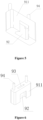
- the Hall sensor 40 includes a sensing portion 41, a connecting portion 42, and a package portion 43.
- the connecting portion 42 includes a second pin 421, and the package portion 43 is formed through injection molding by using the sensing portion 41 and the second pin 421 as an insert.
- the package portion 43 includes a first end 431 and a second end 432.
- the connecting portion 42 is connected to the first end 432, the sensing portion 41 is arranged between the first end 431 and the second end 432, and the connecting portion 42 is electrically connected to the circuit board 31 and fixed to the circuit board 31 by welding.
- a first connecting hole 312 is formed in the circuit board 31, and the connecting portion 42 is arranged to pass through the first connecting hole 312 and fixed to the circuit board 31 by welding.
- the sensing portion 41 is fixedly arranged with respect to the circuit board 31 through the package portion 43.
- the mounting portion is a holder 91.
- the holder 91 includes a holder body 911, a first engagement portion, and a second engagement portion.
- the Hall sensor 40 is plugged into the first engagement portion, and at least part of the second engagement portion and part of the circuit board 31 are engaged with each other by interference fit.
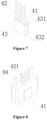
- the first engagement portion includes a mounting groove 92 and a through hole 93 that are formed in the holder body 911.
- the package portion 43 is accommodated in the mounting groove 92, and is tightly fitted against a side wall of the holder body 11 in which the mounting groove 92 is formed.
- the second pin 421 is connected to the circuit board 31 after passing through the through hole 93.
- the circuit board 31 is provided with a first connecting hole 312, and the second pin 421 is fixed to and electrically connected to the circuit board 31 by welding after passing through the first connecting hole 312.
- the second engagement portion includes a connecting post 94 formed at an end of the holder body 911.
- the connecting post 94 and the holder body 911 are integrally through injection molding.
- a second connecting hole 313 corresponding to the connecting post is formed in the circuit board, and the connecting post 94 is plugged into the second connecting hole 313 and is connected with the circuit board 31 by interference fit.
- a length of the second pin 421 is larger than or equal to a length of the connecting post 94, and in this way, a distance between the Hall sensor 40 and the circuit board 31 is limited by the lengths of the second pin 421 and the connecting post 94 in this embodiment.
- the holder 91 and the Hall sensor 40 are first assembled to form an assembly, and then the assembly is assembled with the circuit board 31.
- the connecting portion of the Hall sensor 40 is the second pin 421, and the second pin 421 provides electrical connection between the Hall sensor 40 and the circuit board 31.
- the package portion 43 and the sensing portion 41 are fixedly connected to the circuit board 31 through the holder 91, and the Hall sensor 31 is fixedly connected to the holder 91.
- the holder 91 is made of plastic, and strength of the holder 91 is higher than strength of the second pin 421 to maintain the position of the Hall sensor 40 relative to the circuit board 31, which is beneficial for improving the connection strength between the Hall sensor 40 and the circuit board 31, especially in a case that an operating environment of the electronic expansion valve is an air conditioning system of a vehicle where vibration generated during running of the vehicle transmitted to the electronic expansion valve causes position changes of a sensing surface of the Hall sensor and results in instable feedback signals.
- the Hall sensor and the circuit board are engaged with each other by the holder and the circuit board is fixed to the box body, which is beneficial for improving the connection stability of the Hall sensor.
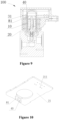
- Figures 9 to 14 are schematic views of an electronic expansion valve according to a second embodiment (not according to the invention as defined by the claims), which mainly differs from the first embodiment in that the mounting portion is an adapter plate 81.
- the Hall sensor 40 includes a sensing portion 41, a connecting portion 42 and a package portion 43.
- the package portion 43 includes a first end 431 and a second end 432. The first end 432 and the second end 433 are arranged opposite to each other.
- the sensing portion 41 is formed at the second end 432, and the connecting portion 42 is a lead formed at the first end.
- the adapter plate 81 is provided with a bonding pad, and the Hall sensor 40 is electrically connected to the bonding pad of the adapter plate 81 through the lead, where a length by which the lead protrudes from the first end 431 is smaller than a length by which the second pin 421 protrudes from the first end 431 in the first embodiment.
- the distance between the Hall sensor 40 and the circuit board 31 is limited by the adapter plate 81.
- a length of the Hall sensor can be shortened, which is beneficial for miniaturizing the Hall sensor 40 and simplifying the assembly process of the electronic expansion valve.
- the adapter plate 81 is plugged into the circuit board 31, where the adapter plate 81 is provided with a plug 811 and the circuit board 31 is provided with a socket 314.
- the adapter plate 81 and the circuit board 31 may also be fixedly connected to each other by welding, where a first bonding pad is formed on the circuit board, a second bonding pad is formed at an end of the adapter plate and the first bonding pad and the second bonding pad are fixed to and electrically connected to each other by welding, which is beneficial for improving the connection strength between the adapter plate 81 and the circuit board 31.
- a connecting circuit of the Hall sensor 40 can be provided on the adapter plate 81 to facilitate saving the layout space of the circuit board 31.
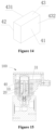
- Figures 15 to 17 are schematic views of an electronic expansion valve according to a third embodiment (not according to the invention as defined by the claims), which mainly differs from the first embodiment in the following.
- the Hall sensor 40 includes a sensing portion 41, a connecting portion 42 and a package portion 43.
- the package portion 43 is fixed to the sensing portion 41 through injection molding.
- the package portion 43 includes a first end 431 and a second end 432.
- the connecting portion 42 is a lead formed at the first end, a bonding pad is formed on the circuit board 31, and the lead is fixed to the bonding pad by welding. Since the connecting portion 42 is a lead, a length of the connecting portion 42 is short, which is beneficial for improving the connection stability between the Hall sensor and the circuit board.
- the length and strength of the Hall sensor 40 are increased by the package portion 43, thereby improving the connection stability of the Hall sensor.
- the electronic expansion valve according to this embodiment has a simpler structure than that according to the first embodiment and the second embodiment.
Landscapes
- Engineering & Computer Science (AREA)
- General Engineering & Computer Science (AREA)
- Mechanical Engineering (AREA)
- Physics & Mathematics (AREA)
- Thermal Sciences (AREA)
- Electromagnetism (AREA)
- Condensed Matter Physics & Semiconductors (AREA)
- General Physics & Mathematics (AREA)
- Measurement Of Length, Angles, Or The Like Using Electric Or Magnetic Means (AREA)
- Indication Of The Valve Opening Or Closing Status (AREA)
- Electrically Driven Valve-Operating Means (AREA)
- Transmission And Conversion Of Sensor Element Output (AREA)
Description
- The present application claims the priority to
Chinese patent application No. 201710889387.4, titled "ELECTRONIC EXPANSION VALVE", filed with the China National Intellectual Property Administration on September 27, 2017 - The present disclosure relates to flow control devices, and in particular to an electric flow control device.
- An electronic expansion valve includes a stepping motor. The stepping motor is controlled to rotate by a controller, and rotor locking may occur in the stepping motor due to existence of an obstacle during rotation of the stepping motor. In order to detect whether the stepping motor is operating normally, the electronic expansion valve needs to be detected with a detecting element. For example,
US 6 460 567 B1 discloses a motor operated valve including a valve body with an inlet and outlet and a valve seat therebetween, a valve core reciprocates between open and closed positions by threads of the valve core cooperating with threads on a shaft which rotates with the armature of the motor, the armature has a plurality of spaced apart permanent magnets, a bearing assembly, and is enclosed by a magnetically transparent enclosure closed at one end and hermetically sealed at its other end to the valve body, and lying closely outside the enclosure is a drive stator that includes drive windings and plural Hall-effect devices for commutation of the windings;JP 2003 329698 A Hall IC unit 20 is arranged in the periphery of acase 12, and magnetism of a detection magnet drum 13c of therotor 13 is detected by theIC unit 20 to detect the stop of therotor 13.ES 1 077 252 UJP 2010 078002 A EGR valve 1 includes a valve seat 4 arranged in the flow passage 3 of a housing, the valve body to be seated on the valve seat 4, a valve stem 6 integrated with the valve body 5, an actuator 7 for driving the valve stem 6 together with the valve body 5, a lift sensor 8 for detecting the position of the valve element 7 to the valve seat 4 in a non-contact state, the lift sensor 8 includes a magnet and Hall IC oppositely arranged to the valve stem 6 via an air gap, and the magnet and the Hall IC are fixed to a yoke.EP 1 160 887 A2CN 101 858 725 A - How to ensure the stability of the detecting element is an urgent problem to be solved.
- One object of the present disclosure is to provide an electronic expansion valve which has a simple structure and can detect the operating state of the electronic expansion valve.
- The invention is set out in the appended set of claims.
-
-
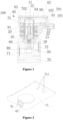
Figure 1 is a schematic view showing the structure of an electronic expansion valve according to a first embodiment; -
Figure 2 is a schematic view showing the structure of a combination of the circuit board, the Hall holder, and the Hall sensor inFigure 1 from one perspective; -
Figure 3 is a schematic view showing the structure of the combination of the circuit board, the Hall holder, and the Hall sensor inFigure 1 from another perspective; -
Figure 4 is a schematic view showing the structure of the circuit board inFigure 3 ; -
Figure 5 is a schematic view showing the structure of the Hall holder inFigure 2 from one perspective; -
Figure 6 is a schematic view showing the structure of the Hall holder inFigure 2 from another perspective; -
Figure 7 is a schematic view showing the structure of the Hall sensor inFigure 2 ; -
Figure 8 is a schematic view showing the structure of a combination of the Hall holder and the Hall sensor inFigure 2 ; -
Figure 9 is a schematic view showing the structure of an electronic expansion valve according to a second embodiment (not according to the invention as defined by the claims); -
Figure 10 is a schematic view showing the structure of a combination of the circuit board, the adapter plate, and the Hall sensor inFigure 9 from one perspective; -
Figure 11 is a schematic view showing the structure of the combination of the circuit board, the adapter plate, and the Hall sensor inFigure 9 from another perspective; -
Figure 12 is a schematic view showing the structure of the circuit board inFigure 11 ; -
Figure 13 is a schematic view showing the structure of a combination of the adapter plate and the Hall sensor inFigure 10 ; -
Figure 14 is a schematic view showing the structure of the Hall sensor inFigure 13 ; -
Figure 15 is a schematic view showing the structure of an electronic expansion valve according to a third embodiment (not according to the invention as defined by the claims); -
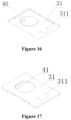
Figure 16 is a schematic view showing the structure of a combination of the circuit board and the Hall sensor inFigure 15 from one perspective; -
Figure 17 is a schematic view showing the structure of the combination of the circuit board and the Hall sensor inFigure 15 from another perspective; -
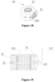
Figure 18 is a schematic view showing the structure of a stator assembly according to the above embodiments; and -
Figure 19 is a schematic cross-sectional view of the stator assembly inFigure 18 . - The present disclosure will be further described hereinafter in conjunction with the drawings and some specific embodiments.
- Referring to
Figures 1 ,9 and15 , anelectronic expansion valve 100 includes arotor 10 and astator 20, thestator 20 is arranged around therotor 10, therotor 10 includes a permanent magnet, the permanent magnet includes at least two pairs of magnetic poles, and thestator 20 includes acoil 21 and acoil bobbin 22. Thecoil bobbin 22 provides support for thecoil 21, and thecoil 21 is energized by a current that changes according to a certain law, thereby forming an excited magnetic field at an inner circumference of thestator 20. The magnetic field of the permanent magnet of therotor 10 interacts with the excited magnetic field of thestator 20, and therotor 10 is rotatable about a central axis. - The
electronic expansion valve 100 further includes a controller and aHall sensor 40. TheHall sensor 40 is configured to sense a magnetic pole change of therotor 10 and form a feedback signal, and may be a position sensor, and the feedback signal includes a Hall signal. The controller includes acircuit board 31 and a processor (not shown), and the processor is fixed to thecircuit board 31. The processor is configured to send a control signal to thestator 20 based on a collected feedback signal. A power supply supplies power to thestator 20 and the controller. The controller may be a part of the electronic expansion valve or may be placed in a system to which the electronic expansion valve is applied, such as an air conditioning system or a higher-level automotive controller, and by providing a driver for receiving the control signal and converting the control signal into a drive signal in the electronic expansion valve, the object of the present disclosure is achieved. This embodiment will be described with the controller being a part of the electronic expansion valve. - The
electronic expansion valve 100 further includes avalve needle 50, avalve seat 60, avalve body 70, and avalve port member 80. A valve port is formed by thevalve port member 80, and afirst channel 71 and asecond channel 72 are formed in the valve body. Thefirst channel 71 and thesecond channel 72 are arranged at two sides of the valve port, and thevalve needle 50 is driven to rotate by therotor 10. Specifically, thevalve needle 50 and therotor 10 moves between a top dead center and a bottom dead center, and in a case that thevalve needle 50 is at the bottom dead center, the valve port is closed, and thefirst channel 71 and thesecond channel 72 on two sides of the valve port are cut off; as thevalve needle 50 moves from the bottom dead center to the top dead center, the valve port is gradually opened, the channels on two sides are communicated with each other through the valve port, and after thevalve needle 50 reaches the top dead center, the opening of the valve port is maximized. In this embodiment, a valve port is formed in thevalve port member 80, thevalve port member 80 is fixedly connected to thevalve body 70, thevalve seat 60 is fixedly connected to thevalve body 70, and thevalve needle 50 is connected to therotor 10. In practice, the valve port may also be formed in thevalve body 70, in which case thevalve port member 80 is not required. In the embodiment, thevalve port member 80 and thevalve body 70 may be individually provided and separately formed, which is beneficial for reducing a process difficulty of a mold and improving processing precision of the valve port. - Referring to
Figure 1 , theelectronic expansion valve 100 further includes alead screw 11, anut member 12, and astopper portion 13. Thenut member 12 is sleeved around thelead screw 11, and thenut member 12 and thelead screw 11 are fitted with each other by means of screw thread. Thenut member 12 is fixedly arranged relative to thevalve seat 60, thelead screw 11 is movable upward or downward relative to thenut member 12, and thestopper portion 13 and thelead screw 11 are fixedly connected to each other through a connecting plate. Thestopper portion 13 moves upward or downward relative to thenut member 12, and the movement of thelead screw 11 is limited between the top dead center and the bottom dead center by cooperation of the stopper portion with thenut member 12. Since thevalve needle 50 can drive thelead screw 11 to move, the movement of thevalve needle 50 is limited within the distance between the top dead center and the bottom dead center. Anelastic member 18 is provided between thevalve needle 50 and thelead screw 11, so that when thevalve needle 50 is moved to the bottom dead center, thevalve needle 50 and thevalve port member 80 elastically contact with each other, providing a buffer between thevalve needle 50 and thevalve port member 80, and thereby facilitating improving the service life of thevalve needle 50 and thevalve port member 80. - The
electronic expansion valve 100 further includes a sleeve 90 which isolates thestator 20 and therotor 10 from each other. The sleeve 90 is in fixed and sealed connection with thevalve seat 60 and is a metal piece. To ensure that the movement of thevalve needle 50 is not interfered, a length of the sleeve 90 is larger than a sum of a length of therotor 10 and a running distance of thevalve needle 50. - Referring to
Figures 18 and 19 , thestator 20 includes acoil 21, acoil bobbin 22, and astator housing 23, and further includes astator pole plate 221. Thestator pole plate 221 is provided with a claw pole for generating an alternating magnetic field, and thestator housing 23 covers an outer circumference of thecoil bobbin 22 and thecoil 21. - The
electronic expansion valve 100 further includes afirst pin 51. Thefirst pin 51 is integrally formed, and is fixedly connected to thestator 20. Thefirst pin 51 electrically connects thecircuit board 40 to thestator 20. Thefirst pin 51 includes afirst portion 511 and asecond portion 512, thefirst portion 511 is electrically connected to thecircuit board 31, and thesecond portion 512 is electrically connected to thestator 20. Thecoil bobbin 22 includes a fixingportion 222, thesecond portion 512 and the fixingportion 222 are connected to each other by transition fit or clearance fit, thesecond portion 512 is fixed to the coil by welding, and thefirst portion 511 and thesecond portion 512 presents a L-like shape. Such a configuration makes it easier to form the pin, in which thefirst pin 51 is first fixedly connected to thestator 20, an end of thecoil 21 is electrically connected to thesecond portion 512 and then thefirst pin 51 is bent by 90 degrees to connect to thecircuit board 31. - The
circuit board 31 has elements fixed thereon, and thecircuit board 31 is placed as close as possible to thestator 20 without hindering the elements, which is beneficial for reducing a length of thefirst portion 511, thereby facilitating the connection reliability of thefirst pin 51. Apin hole 311 is formed in thecircuit board 31, and thefirst portion 511 of thefirst pin 51 is electrically connected to thecircuit board 31 through thepin hole 311. - The
electronic expansion valve 100 further includes an injection molding portion formed by using thestator 20 as an insert. The injection molding portion includes afirst side wall 61 and a first bottom 62, afirst cavity 701 is enclosed by thefirst side wall 61 and the first bottom 62, and thefirst cavity 701 and thestator 2 are arranged along an axial direction of the electronic expansion valve. Theinjection molding portion 60 includes asecond side wall 63 and a second bottom 64, and asecond cavity 702 is enclosed by thesecond side wall 63 and the second bottom and is arranged in communication with an inner cavity of thestator 20. Thecircuit board 31 and theHall sensor 40 are arranged in thefirst cavity 701, and thefirst cavity 701 is not in communication with thesecond cavity 702. In this embodiment, thesecond side wall 63 and second bottom 64 are a part of thefirst bottom 62. - Referring to
Figures 1 ,9 , and15 , in the axial direction of theelectronic expansion valve 100, theHall sensor 40 is arranged between thecircuit board 31 and thestator 20; in a radial direction of theelectronic expansion valve 100, theHall sensor 40 is arranged at the periphery of therotor 10 and is placed as close as possible to therotor 10; therotor 10 and thestator 20 are isolated from each other by the sleeve 90, and thicknesses of the sleeve 90 and thesecond side wall 63 are as small as possible under the condition strength thereof is guaranteed, which is beneficial for magnetic transfer. - The
rotor 10 includes at least two pairs of magnetic poles, each pair of magnetic poles includes an N pole and an S pole, and N poles and S poles are alternately arranged in a circumferential direction of the rotor. In this embodiment, the electronic expansion valve employs a two-phase stepping motor with twelve pairs of poles, and therotor 10 includes twelve N poles and twelve S poles. TheHall sensor 40 is located at the periphery of therotor 10 and close to therotor 10. When therotor 10 rotates, the N poles and S poles of therotor 10 alternately pass by theHall sensor 40, theHall sensor 40 generates a periodic feedback signal, and the feedback signal is a square wave signal. The controller collects the feedback signal and determines an operating state of the electronic expansion valve by a state of the feedback signal, where the operating state of the electronic expansion valve includes normal operation and rotor locking. - The
Hall sensor 40 includes asensing portion 41. A sensing surface of thesensing portion 41 of theHall sensor 40 is tightly arranged against an outer circumference of thesecond side wall 63, to ensure the sensitivity of theHall sensor 40. The length of therotor 10 is larger than a sum of a length of the coil bobbin and a length of the sensing portion of theHall sensor 40; or during the entire operation process of the rotor, the sensing portion is always located in a corresponding radial region between two axial ends of the permanent magnet; when the rotor is at the bottom dead center, at least part of a projection of the sensing portion in the axial direction of the rotor overlaps with at least part of a projection of the permanent magnet in the axial direction of the rotor; or thesensing portion 41 is always located between two ends of the permanent magnet during the entire operation process of the rotor, which is beneficial for ensuring the detecting accuracy of theHall sensor 40. -
Figures 1 to 8 are schematic views of an electronic expansion valve according to a first embodiment according to the invention. - The
electronic expansion valve 100 further includes abox body 101, and a box cavity is formed in thebox body 101. Thebox body 101 includes afirst side wall 61 and a first bottom 62. Thecircuit board 31 and theHall sensor 40 are both arranged in the box cavity. Theelectronic expansion valve 100 further includes abox cover 102. In this embodiment, the box cavity is thefirst cavity 701. In practice, the box cavity may be larger than thefirst cavity 701, for example, an inner cavity may be formed by thecover 102 and the box cavity may include the first cavity and the inner cavity. - In this embodiment, as shown in
Figures 2 to 8 , theHall sensor 40 includes asensing portion 41, a connectingportion 42, and apackage portion 43. The connectingportion 42 includes asecond pin 421, and thepackage portion 43 is formed through injection molding by using thesensing portion 41 and thesecond pin 421 as an insert. Thepackage portion 43 includes afirst end 431 and asecond end 432. The connectingportion 42 is connected to thefirst end 432, the sensingportion 41 is arranged between thefirst end 431 and thesecond end 432, and the connectingportion 42 is electrically connected to thecircuit board 31 and fixed to thecircuit board 31 by welding. Specifically, a first connectinghole 312 is formed in thecircuit board 31, and the connectingportion 42 is arranged to pass through the first connectinghole 312 and fixed to thecircuit board 31 by welding. The sensingportion 41 is fixedly arranged with respect to thecircuit board 31 through thepackage portion 43. - In this embodiment, the mounting portion is a
holder 91. Theholder 91 includes aholder body 911, a first engagement portion, and a second engagement portion. TheHall sensor 40 is plugged into the first engagement portion, and at least part of the second engagement portion and part of thecircuit board 31 are engaged with each other by interference fit. - In this embodiment, the first engagement portion includes a mounting
groove 92 and a throughhole 93 that are formed in theholder body 911. Thepackage portion 43 is accommodated in the mountinggroove 92, and is tightly fitted against a side wall of theholder body 11 in which the mountinggroove 92 is formed. Thesecond pin 421 is connected to thecircuit board 31 after passing through the throughhole 93. Thecircuit board 31 is provided with a first connectinghole 312, and thesecond pin 421 is fixed to and electrically connected to thecircuit board 31 by welding after passing through the first connectinghole 312. The second engagement portion includes a connectingpost 94 formed at an end of theholder body 911. The connectingpost 94 and theholder body 911 are integrally through injection molding. A second connectinghole 313 corresponding to the connecting post is formed in the circuit board, and the connectingpost 94 is plugged into the second connectinghole 313 and is connected with thecircuit board 31 by interference fit. In order to ensure the connection reliability, a length of thesecond pin 421 is larger than or equal to a length of the connectingpost 94, and in this way, a distance between theHall sensor 40 and thecircuit board 31 is limited by the lengths of thesecond pin 421 and the connectingpost 94 in this embodiment. - In this embodiment, in assembling the electronic expansion valve, the
holder 91 and theHall sensor 40 are first assembled to form an assembly, and then the assembly is assembled with thecircuit board 31. The connecting portion of theHall sensor 40 is thesecond pin 421, and thesecond pin 421 provides electrical connection between theHall sensor 40 and thecircuit board 31. Thepackage portion 43 and thesensing portion 41 are fixedly connected to thecircuit board 31 through theholder 91, and theHall sensor 31 is fixedly connected to theholder 91. Theholder 91 is made of plastic, and strength of theholder 91 is higher than strength of thesecond pin 421 to maintain the position of theHall sensor 40 relative to thecircuit board 31, which is beneficial for improving the connection strength between theHall sensor 40 and thecircuit board 31, especially in a case that an operating environment of the electronic expansion valve is an air conditioning system of a vehicle where vibration generated during running of the vehicle transmitted to the electronic expansion valve causes position changes of a sensing surface of the Hall sensor and results in instable feedback signals. In this embodiment, the Hall sensor and the circuit board are engaged with each other by the holder and the circuit board is fixed to the box body, which is beneficial for improving the connection stability of the Hall sensor. -
Figures 9 to 14 are schematic views of an electronic expansion valve according to a second embodiment (not according to the invention as defined by the claims), which mainly differs from the first embodiment in that the mounting portion is anadapter plate 81. TheHall sensor 40 includes asensing portion 41, a connectingportion 42 and apackage portion 43. Thepackage portion 43 includes afirst end 431 and asecond end 432. Thefirst end 432 and the second end 433 are arranged opposite to each other. The sensingportion 41 is formed at thesecond end 432, and the connectingportion 42 is a lead formed at the first end. Theadapter plate 81 is provided with a bonding pad, and theHall sensor 40 is electrically connected to the bonding pad of theadapter plate 81 through the lead, where a length by which the lead protrudes from thefirst end 431 is smaller than a length by which thesecond pin 421 protrudes from thefirst end 431 in the first embodiment. The distance between theHall sensor 40 and thecircuit board 31 is limited by theadapter plate 81. A length of the Hall sensor can be shortened, which is beneficial for miniaturizing theHall sensor 40 and simplifying the assembly process of the electronic expansion valve. Theadapter plate 81 is plugged into thecircuit board 31, where theadapter plate 81 is provided with aplug 811 and thecircuit board 31 is provided with asocket 314. Theadapter plate 81 and thecircuit board 31 may also be fixedly connected to each other by welding, where a first bonding pad is formed on the circuit board, a second bonding pad is formed at an end of the adapter plate and the first bonding pad and the second bonding pad are fixed to and electrically connected to each other by welding, which is beneficial for improving the connection strength between theadapter plate 81 and thecircuit board 31. A connecting circuit of theHall sensor 40 can be provided on theadapter plate 81 to facilitate saving the layout space of thecircuit board 31. -
Figures 15 to 17 are schematic views of an electronic expansion valve according to a third embodiment (not according to the invention as defined by the claims), which mainly differs from the first embodiment in the following. In conjunction withFigure 14 , theHall sensor 40 includes asensing portion 41, a connectingportion 42 and apackage portion 43. Thepackage portion 43 is fixed to thesensing portion 41 through injection molding. Thepackage portion 43 includes afirst end 431 and asecond end 432. The connectingportion 42 is a lead formed at the first end, a bonding pad is formed on thecircuit board 31, and the lead is fixed to the bonding pad by welding. Since the connectingportion 42 is a lead, a length of the connectingportion 42 is short, which is beneficial for improving the connection stability between the Hall sensor and the circuit board. Besides, in order to ensure that thesensing portion 41 is located between top and bottom end surfaces of the permanent magnet and to guarantee the connection of theHall sensor 40 to thecircuit board 31, the length and strength of theHall sensor 40 are increased by thepackage portion 43, thereby improving the connection stability of the Hall sensor. The electronic expansion valve according to this embodiment has a simpler structure than that according to the first embodiment and the second embodiment.
Claims (5)
- An electronic expansion valve (100), comprising:a rotor (10), a stator (20), and a circuit board (31), the rotor (10) comprising a permanent magnet, the permanent magnet comprising at least two pairs of magnetic poles, the stator (20) comprising a coil (21) and a coil bobbin (22), the coil (21) being supported by the coil bobbin (22) and electrically connected to the circuit board (31), and the coil bobbin (22) being arranged around the permanent magnet,wherein the electronic expansion valve (100) further comprises a Hall sensor (40), the Hall sensor (40) is arranged at a periphery of the permanent magnet and is electrically connected to the circuit board (31), the Hall sensor (40) comprises a sensing portion (41) and a connecting portion (42), the sensing portion (41) is electrically connected to the circuit board (31) through the connecting portion (42), and the sensing portion (41) is configured to sense a magnetic pole change of the permanent magnet;the sensing portion (41) is always located in a corresponding radial region between two axial ends of the permanent magnet during an entire operation process of the rotor (10), or in a case that the rotor (10) is located at a bottom dead center, at least part of a projection of the sensing portion (41) in an axial direction of the rotor (10) overlaps with at least part of a projection of the permanent magnet in the axial direction of the rotor (10);the electronic expansion valve (100) further comprises a box body (101), part of the box body (101) is formed through injection molding by using the stator (20) as an insert, a box cavity is formed in the box body (101), and the circuit board (31) and the Hall sensor (40) are both arranged in the box cavity;the electronic expansion valve (100) comprises a mounting portion, the sensing portion (41) is fixedly connected to the mounting portion, and the mounting portion is arranged between the Hall sensor (40) and the circuit board (31),wherein the mounting portion is a holder (91), which comprises a holder body (911), a first engagement portion and a second engagement portion, the Hall sensor (40) is plugged into the first engagement portion, at least part of the second engagement portion and at least part of the circuit board (31) are engaged with each other and fixed to each other by welding, the Hall sensor (40) and the circuit board (31) are engaged with each other by the holder (91) and the circuit board (31) is fixed to the box body (101).
- The electronic expansion valve (100) according to claim 1, wherein the mounting portion is a part of the Hall sensor (40).
- The electronic expansion valve (100) according to claim 1, wherein the Hall sensor (40) comprises a package portion (43), the package portion (43) is formed through injection molding by using the sensing portion (41) as an insert, the connecting portion (42) comprises a pin (51, 421), the pin (51, 421) is fixed to the package portion (43) through injection molding, the first engagement portion comprises a mounting groove (92) and a through hole (93), the package portion (43) is accommodated in the mounting groove (92), the pin (51, 421) is connected to the circuit board (31) after passing through the through hole (93), the circuit board (31) is provided with a first connecting hole (312), and the pin (51, 421) is fixed to and electrically connected to the circuit board (31) by welding after passing through the first connecting hole (312).
- The electronic expansion valve (100) according to claim 3, wherein the second engagement portion comprises a connecting post (94), a length of the pin (51, 421) is larger than or equal to a length of the connecting post (94), the circuit board (31) is provided with a second connecting hole (313), and the connection post is plugged into the second connecting hole (313) and fixed to the circuit board (31) by interference fit.
- The electronic expansion valve (100) according to claim 1, wherein the mounting portion comprises a package portion (43), the package portion (43) is fixed to the sensing portion (41) through injection molding, the connecting portion (42) is provided with a lead at an end of the package portion (43), a bonding pad is formed on the circuit board (31), the lead is fixed to the bonding pad by welding, and the package portion (43) is arranged between the sensing portion (41) and the circuit board (31).
Applications Claiming Priority (2)
| Application Number | Priority Date | Filing Date | Title |
|---|---|---|---|
| CN201710889387.4A CN109555891B (en) | 2017-09-27 | 2017-09-27 | Electronic expansion valve |
| PCT/CN2018/081274 WO2019062057A1 (en) | 2017-09-27 | 2018-03-30 | Electronic expansion valve |
Publications (3)
| Publication Number | Publication Date |
|---|---|
| EP3690294A1 EP3690294A1 (en) | 2020-08-05 |
| EP3690294A4 EP3690294A4 (en) | 2021-06-16 |
| EP3690294B1 true EP3690294B1 (en) | 2025-04-30 |
Family
ID=65863913
Family Applications (1)
| Application Number | Title | Priority Date | Filing Date |
|---|---|---|---|
| EP18863657.5A Active EP3690294B1 (en) | 2017-09-27 | 2018-03-30 | ELECTRONIC EXPANSION VALVE |
Country Status (6)
| Country | Link |
|---|---|
| US (1) | US11585458B2 (en) |
| EP (1) | EP3690294B1 (en) |
| JP (1) | JP6985505B2 (en) |
| KR (1) | KR102236664B1 (en) |
| CN (1) | CN109555891B (en) |
| WO (1) | WO2019062057A1 (en) |
Families Citing this family (23)
| Publication number | Priority date | Publication date | Assignee | Title |
|---|---|---|---|---|
| DE102019206197A1 (en) | 2019-04-30 | 2020-11-05 | Mahle International Gmbh | Expansion valve |
| CN112576762A (en) * | 2019-09-27 | 2021-03-30 | 杭州三花研究院有限公司 | Electric valve |
| DE102020124871A1 (en) * | 2019-12-04 | 2021-06-10 | ECO Holding 1 GmbH | Expansion valve |
| CN112984127A (en) * | 2019-12-12 | 2021-06-18 | 浙江三花汽车零部件有限公司 | Electronic expansion valve |
| CN113090763A (en) * | 2019-12-20 | 2021-07-09 | 杭州三花研究院有限公司 | Electronic expansion valve |
| CN113108109B (en) * | 2019-12-24 | 2025-10-03 | 浙江三花智能控制股份有限公司 | An electric valve |
| CN113517105B (en) * | 2020-04-10 | 2023-11-28 | 盾安环境技术有限公司 | Electronic coil and electronic expansion valve with same |
| DE102020112658B4 (en) | 2020-05-11 | 2022-05-19 | Pierburg Gmbh | Expansion valve arrangement for a refrigeration or air conditioning circuit |
| CN113758063B (en) * | 2020-05-19 | 2023-07-25 | 法雷奥汽车空调湖北有限公司 | Electronic expansion valve, thermal management assembly and automobile air conditioning system |
| JP6857273B1 (en) * | 2020-08-18 | 2021-04-14 | 太平洋工業株式会社 | IC holder, electric valve, fluid control device and its manufacturing method |
| CN112032313A (en) * | 2020-08-28 | 2020-12-04 | 北京京仪自动化装备技术有限公司 | Expansion valve and refrigeration control system |
| CN114458806A (en) * | 2020-11-10 | 2022-05-10 | 盾安汽车热管理科技有限公司 | Electronic expansion valve and monitoring method for electronic expansion valve |
| DE102020215275A1 (en) * | 2020-12-03 | 2022-06-09 | Mahle International Gmbh | expansion valve |
| CN112555427B (en) * | 2020-12-11 | 2022-07-22 | 上海交通大学 | Electronic throttling device for refrigeration system |
| CN115027196B (en) * | 2021-03-05 | 2025-09-23 | 法雷奥热系统公司 | An electronic expansion valve |
| CN115388582B (en) * | 2021-05-24 | 2023-12-26 | 盾安汽车热管理科技有限公司 | Control method and control device and electronic expansion valve |
| CN215806673U (en) * | 2021-06-29 | 2022-02-11 | 盾安汽车热管理科技有限公司 | Stator module and electronic expansion valve with same |
| CN114151549A (en) * | 2021-12-07 | 2022-03-08 | 北京星空建腾电子科技有限公司 | Electronic expansion valve and refrigerating system |
| KR20230159030A (en) | 2022-05-13 | 2023-11-21 | 한온시스템 주식회사 | Ball valve |
| KR20230159031A (en) | 2022-05-13 | 2023-11-21 | 한온시스템 주식회사 | Ball valve and ball valve module having the same |
| JP7592323B2 (en) | 2022-08-23 | 2024-12-02 | 株式会社不二工機 | Stator unit, motorized valve and motorized valve device |
| CN115750799A (en) * | 2022-11-18 | 2023-03-07 | 嘉兴科奥电磁技术有限公司 | Electronic expansion valve |
| DE102023202886A1 (en) * | 2023-03-29 | 2024-10-02 | Mahle International Gmbh | Electromotive expansion valve and refrigeration circuit |
Citations (19)
| Publication number | Priority date | Publication date | Assignee | Title |
|---|---|---|---|---|
| DE4317259A1 (en) | 1992-05-22 | 1993-11-25 | Nippon Denso Co | Electrical control device |
| DE19748982A1 (en) | 1997-11-06 | 1999-06-02 | Bosch Gmbh Robert | Component holder for a Hall sensor and method for producing a component holder |
| EP1160887A2 (en) | 2000-05-15 | 2001-12-05 | Mannesmann VDO Aktiengesellschaft | Hall-effect sensor element with integrated condensers |
| US6460567B1 (en) | 1999-11-24 | 2002-10-08 | Hansen Technologies Corpporation | Sealed motor driven valve |
| JP2003329698A (en) | 2002-05-16 | 2003-11-19 | Saginomiya Seisakusho Inc | Electric valve, electric valve driving device, electric valve control device, refrigeration cycle device, and air conditioner |
| EP1758228A1 (en) | 2004-05-20 | 2007-02-28 | Kabushiki Kaisha Toshiba | Motor |
| DE112007000129T5 (en) | 2006-01-10 | 2008-11-13 | Mitsuba Corp., Kiryu | Rotating electrical machine |
| JP2010078002A (en) | 2008-09-24 | 2010-04-08 | Aisan Ind Co Ltd | Flow control valve |
| DE102008053573A1 (en) | 2008-10-15 | 2010-04-22 | Bühler Motor GmbH | Actuating drive for actuating exhaust gas recirculation valve in motor vehicle, has sensor connections formed as single piece with guide plates, where guide plates are formed as integral components of transmission housing |
| DE102009059249A1 (en) | 2009-03-05 | 2010-09-09 | Zhongshan Broad-Ocean Motor Co., Ltd. | Sensor device for sensing the position of a rotor |
| CN101858725A (en) | 2010-04-30 | 2010-10-13 | 锦州海伯伦汽车电子有限公司 | Insulating bracket in Hall displacement transducer |
| DE112009000845T5 (en) | 2008-06-13 | 2011-04-28 | Mitsubishi Electric Corp. | Motor position structure |
| US20110254410A1 (en) | 2010-04-19 | 2011-10-20 | Yamada Manufacturing Co., Ltd. | Electric water pump |
| ES1077252U (en) | 2012-05-29 | 2012-06-22 | Bitron Industrie España, S.A. | Bistable solenoid valve for the regulation of the step of a fluid (Machine-translation by Google Translate, not legally binding) |
| US20130056660A1 (en) | 2010-05-10 | 2013-03-07 | Borgwarner Inc. | Electronic coolant valve with integral actuator mechanism |
| EP2690763A1 (en) | 2012-07-26 | 2014-01-29 | Pierburg Pump Technology GmbH | Electric fluid pump for a motor vehicle |
| US20150188394A1 (en) | 2013-12-30 | 2015-07-02 | Samsung Electro-Mechanics Co., Ltd. | Motor assembly |
| JP2016220403A (en) | 2015-05-20 | 2016-12-22 | 株式会社不二工機 | Stator unit and motor-operated valve using the same |
| WO2018033025A1 (en) | 2016-08-18 | 2018-02-22 | 杭州三花研究院有限公司 | Electronic expansion valve, control system, and control method |
Family Cites Families (18)
| Publication number | Priority date | Publication date | Assignee | Title |
|---|---|---|---|---|
| JPH03186675A (en) | 1989-12-14 | 1991-08-14 | Ckd Corp | Electric motor-driven flow control valve |
| US5323075A (en) * | 1992-11-20 | 1994-06-21 | Alliedsignal Inc. | Hall effect sensors embedded within two-pole toothless stator assembly |
| CN2155519Y (en) | 1993-06-30 | 1994-02-09 | 李敬茂 | Energy-saving air conditioner |
| US6225716B1 (en) * | 1998-12-15 | 2001-05-01 | Honeywell International Inc | Commutator assembly apparatus for hall sensor devices |
| JP3019858B1 (en) * | 1999-03-31 | 2000-03-13 | 株式会社日立製作所 | Motor drive unit, control conversion unit, and air conditioner |
| KR100375454B1 (en) * | 2000-05-17 | 2003-03-10 | 현대자동차주식회사 | Electronic expansion valve of air conditioner system for automobile |
| JP2004034943A (en) | 2002-07-08 | 2004-02-05 | Tgk Co Ltd | Control method for refrigeration cycle |
| JP4702593B2 (en) | 2004-10-08 | 2011-06-15 | 日本電産株式会社 | motor |
| DE102005027767A1 (en) * | 2005-06-15 | 2006-12-28 | Infineon Technologies Ag | Integrated magnetic sensor component for e.g. measuring magnetic field intensity, has contact surfaces electrically connected with flat conductors by flip-chip-contacts and homogenization disk attached between semiconductor chip and magnet |
| JP2008249148A (en) * | 2008-07-07 | 2008-10-16 | Fuji Koki Corp | Motor driven valve |
| JP2010124519A (en) | 2008-11-17 | 2010-06-03 | Koyo Electronics Ind Co Ltd | Electric motor |
| JP2010124520A (en) | 2008-11-17 | 2010-06-03 | Koyo Electronics Ind Co Ltd | Electric motor |
| CN102853598B (en) * | 2011-06-27 | 2015-04-15 | 浙江三花股份有限公司 | Electronic expansion valve |
| KR20140141858A (en) * | 2013-05-31 | 2014-12-11 | 삼성전기주식회사 | Sensing module |
| US20140353391A1 (en) * | 2013-06-03 | 2014-12-04 | Trane International Inc. | Electronic Expansion Valve |
| CN204300408U (en) * | 2013-11-19 | 2015-04-29 | 浙江盾安禾田金属有限公司 | Electric expansion valve |
| US9599363B1 (en) * | 2014-10-20 | 2017-03-21 | NexRev Inc. | Air curtain for an air handler |
| JP6481155B2 (en) * | 2014-11-25 | 2019-03-13 | 株式会社テージーケー | Motorized valve |
-
2017
- 2017-09-27 CN CN201710889387.4A patent/CN109555891B/en active Active
-
2018
- 2018-03-30 KR KR1020207009774A patent/KR102236664B1/en active Active
- 2018-03-30 US US16/648,648 patent/US11585458B2/en active Active
- 2018-03-30 JP JP2020517313A patent/JP6985505B2/en active Active
- 2018-03-30 EP EP18863657.5A patent/EP3690294B1/en active Active
- 2018-03-30 WO PCT/CN2018/081274 patent/WO2019062057A1/en not_active Ceased
Patent Citations (19)
| Publication number | Priority date | Publication date | Assignee | Title |
|---|---|---|---|---|
| DE4317259A1 (en) | 1992-05-22 | 1993-11-25 | Nippon Denso Co | Electrical control device |
| DE19748982A1 (en) | 1997-11-06 | 1999-06-02 | Bosch Gmbh Robert | Component holder for a Hall sensor and method for producing a component holder |
| US6460567B1 (en) | 1999-11-24 | 2002-10-08 | Hansen Technologies Corpporation | Sealed motor driven valve |
| EP1160887A2 (en) | 2000-05-15 | 2001-12-05 | Mannesmann VDO Aktiengesellschaft | Hall-effect sensor element with integrated condensers |
| JP2003329698A (en) | 2002-05-16 | 2003-11-19 | Saginomiya Seisakusho Inc | Electric valve, electric valve driving device, electric valve control device, refrigeration cycle device, and air conditioner |
| EP1758228A1 (en) | 2004-05-20 | 2007-02-28 | Kabushiki Kaisha Toshiba | Motor |
| DE112007000129T5 (en) | 2006-01-10 | 2008-11-13 | Mitsuba Corp., Kiryu | Rotating electrical machine |
| DE112009000845T5 (en) | 2008-06-13 | 2011-04-28 | Mitsubishi Electric Corp. | Motor position structure |
| JP2010078002A (en) | 2008-09-24 | 2010-04-08 | Aisan Ind Co Ltd | Flow control valve |
| DE102008053573A1 (en) | 2008-10-15 | 2010-04-22 | Bühler Motor GmbH | Actuating drive for actuating exhaust gas recirculation valve in motor vehicle, has sensor connections formed as single piece with guide plates, where guide plates are formed as integral components of transmission housing |
| DE102009059249A1 (en) | 2009-03-05 | 2010-09-09 | Zhongshan Broad-Ocean Motor Co., Ltd. | Sensor device for sensing the position of a rotor |
| US20110254410A1 (en) | 2010-04-19 | 2011-10-20 | Yamada Manufacturing Co., Ltd. | Electric water pump |
| CN101858725A (en) | 2010-04-30 | 2010-10-13 | 锦州海伯伦汽车电子有限公司 | Insulating bracket in Hall displacement transducer |
| US20130056660A1 (en) | 2010-05-10 | 2013-03-07 | Borgwarner Inc. | Electronic coolant valve with integral actuator mechanism |
| ES1077252U (en) | 2012-05-29 | 2012-06-22 | Bitron Industrie España, S.A. | Bistable solenoid valve for the regulation of the step of a fluid (Machine-translation by Google Translate, not legally binding) |
| EP2690763A1 (en) | 2012-07-26 | 2014-01-29 | Pierburg Pump Technology GmbH | Electric fluid pump for a motor vehicle |
| US20150188394A1 (en) | 2013-12-30 | 2015-07-02 | Samsung Electro-Mechanics Co., Ltd. | Motor assembly |
| JP2016220403A (en) | 2015-05-20 | 2016-12-22 | 株式会社不二工機 | Stator unit and motor-operated valve using the same |
| WO2018033025A1 (en) | 2016-08-18 | 2018-02-22 | 杭州三花研究院有限公司 | Electronic expansion valve, control system, and control method |
Also Published As
| Publication number | Publication date |
|---|---|
| US11585458B2 (en) | 2023-02-21 |
| KR102236664B1 (en) | 2021-04-06 |
| JP2021501853A (en) | 2021-01-21 |
| EP3690294A4 (en) | 2021-06-16 |
| WO2019062057A1 (en) | 2019-04-04 |
| CN109555891A (en) | 2019-04-02 |
| US20200232690A1 (en) | 2020-07-23 |
| CN109555891B (en) | 2020-08-25 |
| JP6985505B2 (en) | 2021-12-22 |
| KR20200044956A (en) | 2020-04-29 |
| EP3690294A1 (en) | 2020-08-05 |
Similar Documents
| Publication | Publication Date | Title |
|---|---|---|
| EP3690294B1 (en) | ELECTRONIC EXPANSION VALVE | |
| CN111512079B (en) | Compact control valve | |
| CN107763285B (en) | Control system and control method | |
| US9077231B2 (en) | Motor | |
| JP7368023B2 (en) | electric valve | |
| US10594173B2 (en) | Actuator with coated stator and rotor modules | |
| US20040108779A1 (en) | Electric motor for a pump drive | |
| US11699938B2 (en) | Guiding element for an electric motor | |
| EP3883092B1 (en) | Rotor, motor and brushless motor | |
| WO2019159698A1 (en) | Fluid control valve | |
| USRE47564E1 (en) | Motor | |
| JP7834381B2 (en) | Electric valves and valve devices | |
| CN224006579U (en) | Electric actuator | |
| WO2018193616A1 (en) | Dc motor, egr valve, vg actuator, and wastegate actuator | |
| KR102675544B1 (en) | Brushless motor apparatus provided with enhanced assembly structure of hall sensor module | |
| US12595863B2 (en) | Electric valve | |
| CN216523828U (en) | Rotation angle sensing structure of rotating shaft of machine tool | |
| CN119382430A (en) | Actuator device | |
| CN118076823A (en) | Electric valve | |
| JP2013093931A (en) | Motor |
Legal Events
| Date | Code | Title | Description |
|---|---|---|---|
| STAA | Information on the status of an ep patent application or granted ep patent |
Free format text: STATUS: THE INTERNATIONAL PUBLICATION HAS BEEN MADE |
|
| PUAI | Public reference made under article 153(3) epc to a published international application that has entered the european phase |
Free format text: ORIGINAL CODE: 0009012 |
|
| STAA | Information on the status of an ep patent application or granted ep patent |
Free format text: STATUS: REQUEST FOR EXAMINATION WAS MADE |
|
| 17P | Request for examination filed |
Effective date: 20200312 |
|
| AK | Designated contracting states |
Kind code of ref document: A1 Designated state(s): AL AT BE BG CH CY CZ DE DK EE ES FI FR GB GR HR HU IE IS IT LI LT LU LV MC MK MT NL NO PL PT RO RS SE SI SK SM TR |
|
| AX | Request for extension of the european patent |
Extension state: BA ME |
|
| DAV | Request for validation of the european patent (deleted) | ||
| DAX | Request for extension of the european patent (deleted) | ||
| A4 | Supplementary search report drawn up and despatched |
Effective date: 20210519 |
|
| RAP1 | Party data changed (applicant data changed or rights of an application transferred) |
Owner name: ZHEJIANG SANHUA INTELLIGENT CONTROLS CO., LTD. |
|
| RIC1 | Information provided on ipc code assigned before grant |
Ipc: F16K 31/10 20060101AFI20210512BHEP Ipc: F16K 31/04 20060101ALI20210512BHEP Ipc: F16K 37/00 20060101ALI20210512BHEP Ipc: F25B 41/31 20210101ALI20210512BHEP Ipc: F25B 41/35 20210101ALI20210512BHEP Ipc: G01R 33/00 20060101ALI20210512BHEP Ipc: G01R 33/07 20060101ALI20210512BHEP |
|
| STAA | Information on the status of an ep patent application or granted ep patent |
Free format text: STATUS: EXAMINATION IS IN PROGRESS |
|
| 17Q | First examination report despatched |
Effective date: 20230522 |
|
| GRAP | Despatch of communication of intention to grant a patent |
Free format text: ORIGINAL CODE: EPIDOSNIGR1 |
|
| STAA | Information on the status of an ep patent application or granted ep patent |
Free format text: STATUS: GRANT OF PATENT IS INTENDED |
|
| INTG | Intention to grant announced |
Effective date: 20241107 |
|
| GRAS | Grant fee paid |
Free format text: ORIGINAL CODE: EPIDOSNIGR3 |
|
| GRAA | (expected) grant |
Free format text: ORIGINAL CODE: 0009210 |
|
| STAA | Information on the status of an ep patent application or granted ep patent |
Free format text: STATUS: THE PATENT HAS BEEN GRANTED |
|
| AK | Designated contracting states |
Kind code of ref document: B1 Designated state(s): AL AT BE BG CH CY CZ DE DK EE ES FI FR GB GR HR HU IE IS IT LI LT LU LV MC MK MT NL NO PL PT RO RS SE SI SK SM TR |
|
| REG | Reference to a national code |
Ref country code: CH Ref legal event code: EP Ref country code: GB Ref legal event code: FG4D |
|
| REG | Reference to a national code |
Ref country code: IE Ref legal event code: FG4D |
|
| REG | Reference to a national code |
Ref country code: DE Ref legal event code: R096 Ref document number: 602018081607 Country of ref document: DE |
|
| REG | Reference to a national code |
Ref country code: NL Ref legal event code: MP Effective date: 20250430 |
|
| P01 | Opt-out of the competence of the unified patent court (upc) registered |
Free format text: CASE NUMBER: UPC_APP_2039_3690294/2025 Effective date: 20250731 |
|
| REG | Reference to a national code |
Ref country code: AT Ref legal event code: MK05 Ref document number: 1790281 Country of ref document: AT Kind code of ref document: T Effective date: 20250430 |
|
| PG25 | Lapsed in a contracting state [announced via postgrant information from national office to epo] |
Ref country code: PT Free format text: LAPSE BECAUSE OF FAILURE TO SUBMIT A TRANSLATION OF THE DESCRIPTION OR TO PAY THE FEE WITHIN THE PRESCRIBED TIME-LIMIT Effective date: 20250901 Ref country code: ES Free format text: LAPSE BECAUSE OF FAILURE TO SUBMIT A TRANSLATION OF THE DESCRIPTION OR TO PAY THE FEE WITHIN THE PRESCRIBED TIME-LIMIT Effective date: 20250430 Ref country code: FI Free format text: LAPSE BECAUSE OF FAILURE TO SUBMIT A TRANSLATION OF THE DESCRIPTION OR TO PAY THE FEE WITHIN THE PRESCRIBED TIME-LIMIT Effective date: 20250430 |
|
| REG | Reference to a national code |
Ref country code: LT Ref legal event code: MG9D |
|
| PG25 | Lapsed in a contracting state [announced via postgrant information from national office to epo] |
Ref country code: GR Free format text: LAPSE BECAUSE OF FAILURE TO SUBMIT A TRANSLATION OF THE DESCRIPTION OR TO PAY THE FEE WITHIN THE PRESCRIBED TIME-LIMIT Effective date: 20250731 Ref country code: NO Free format text: LAPSE BECAUSE OF FAILURE TO SUBMIT A TRANSLATION OF THE DESCRIPTION OR TO PAY THE FEE WITHIN THE PRESCRIBED TIME-LIMIT Effective date: 20250730 |
|
| PG25 | Lapsed in a contracting state [announced via postgrant information from national office to epo] |
Ref country code: PL Free format text: LAPSE BECAUSE OF FAILURE TO SUBMIT A TRANSLATION OF THE DESCRIPTION OR TO PAY THE FEE WITHIN THE PRESCRIBED TIME-LIMIT Effective date: 20250430 Ref country code: NL Free format text: LAPSE BECAUSE OF FAILURE TO SUBMIT A TRANSLATION OF THE DESCRIPTION OR TO PAY THE FEE WITHIN THE PRESCRIBED TIME-LIMIT Effective date: 20250430 |
|
| PG25 | Lapsed in a contracting state [announced via postgrant information from national office to epo] |
Ref country code: BG Free format text: LAPSE BECAUSE OF FAILURE TO SUBMIT A TRANSLATION OF THE DESCRIPTION OR TO PAY THE FEE WITHIN THE PRESCRIBED TIME-LIMIT Effective date: 20250430 |
|
| PG25 | Lapsed in a contracting state [announced via postgrant information from national office to epo] |
Ref country code: HR Free format text: LAPSE BECAUSE OF FAILURE TO SUBMIT A TRANSLATION OF THE DESCRIPTION OR TO PAY THE FEE WITHIN THE PRESCRIBED TIME-LIMIT Effective date: 20250430 |
|
| PG25 | Lapsed in a contracting state [announced via postgrant information from national office to epo] |
Ref country code: AT Free format text: LAPSE BECAUSE OF FAILURE TO SUBMIT A TRANSLATION OF THE DESCRIPTION OR TO PAY THE FEE WITHIN THE PRESCRIBED TIME-LIMIT Effective date: 20250430 |
|
| PG25 | Lapsed in a contracting state [announced via postgrant information from national office to epo] |
Ref country code: RS Free format text: LAPSE BECAUSE OF FAILURE TO SUBMIT A TRANSLATION OF THE DESCRIPTION OR TO PAY THE FEE WITHIN THE PRESCRIBED TIME-LIMIT Effective date: 20250731 |
|
| PG25 | Lapsed in a contracting state [announced via postgrant information from national office to epo] |
Ref country code: IS Free format text: LAPSE BECAUSE OF FAILURE TO SUBMIT A TRANSLATION OF THE DESCRIPTION OR TO PAY THE FEE WITHIN THE PRESCRIBED TIME-LIMIT Effective date: 20250830 |
|
| PG25 | Lapsed in a contracting state [announced via postgrant information from national office to epo] |
Ref country code: LV Free format text: LAPSE BECAUSE OF FAILURE TO SUBMIT A TRANSLATION OF THE DESCRIPTION OR TO PAY THE FEE WITHIN THE PRESCRIBED TIME-LIMIT Effective date: 20250430 |
|
| PG25 | Lapsed in a contracting state [announced via postgrant information from national office to epo] |
Ref country code: SM Free format text: LAPSE BECAUSE OF FAILURE TO SUBMIT A TRANSLATION OF THE DESCRIPTION OR TO PAY THE FEE WITHIN THE PRESCRIBED TIME-LIMIT Effective date: 20250430 Ref country code: DK Free format text: LAPSE BECAUSE OF FAILURE TO SUBMIT A TRANSLATION OF THE DESCRIPTION OR TO PAY THE FEE WITHIN THE PRESCRIBED TIME-LIMIT Effective date: 20250430 |
|
| PG25 | Lapsed in a contracting state [announced via postgrant information from national office to epo] |
Ref country code: CZ Free format text: LAPSE BECAUSE OF FAILURE TO SUBMIT A TRANSLATION OF THE DESCRIPTION OR TO PAY THE FEE WITHIN THE PRESCRIBED TIME-LIMIT Effective date: 20250430 |
|
| PG25 | Lapsed in a contracting state [announced via postgrant information from national office to epo] |
Ref country code: EE Free format text: LAPSE BECAUSE OF FAILURE TO SUBMIT A TRANSLATION OF THE DESCRIPTION OR TO PAY THE FEE WITHIN THE PRESCRIBED TIME-LIMIT Effective date: 20250430 |
|
| PG25 | Lapsed in a contracting state [announced via postgrant information from national office to epo] |
Ref country code: SK Free format text: LAPSE BECAUSE OF FAILURE TO SUBMIT A TRANSLATION OF THE DESCRIPTION OR TO PAY THE FEE WITHIN THE PRESCRIBED TIME-LIMIT Effective date: 20250430 Ref country code: RO Free format text: LAPSE BECAUSE OF FAILURE TO SUBMIT A TRANSLATION OF THE DESCRIPTION OR TO PAY THE FEE WITHIN THE PRESCRIBED TIME-LIMIT Effective date: 20250430 |
|
| PG25 | Lapsed in a contracting state [announced via postgrant information from national office to epo] |
Ref country code: IT Free format text: LAPSE BECAUSE OF FAILURE TO SUBMIT A TRANSLATION OF THE DESCRIPTION OR TO PAY THE FEE WITHIN THE PRESCRIBED TIME-LIMIT Effective date: 20250430 |
|
| REG | Reference to a national code |
Ref country code: DE Ref legal event code: R026 Ref document number: 602018081607 Country of ref document: DE |
|
| PLBI | Opposition filed |
Free format text: ORIGINAL CODE: 0009260 |
|
| REG | Reference to a national code |
Ref country code: CH Ref legal event code: L11 Free format text: ST27 STATUS EVENT CODE: U-0-0-L10-L11 (AS PROVIDED BY THE NATIONAL OFFICE) Effective date: 20260211 |
|
| PLAX | Notice of opposition and request to file observation + time limit sent |
Free format text: ORIGINAL CODE: EPIDOSNOBS2 |
|
| PLAB | Opposition data, opponent's data or that of the opponent's representative modified |
Free format text: ORIGINAL CODE: 0009299OPPO |
|
| 26 | Opposition filed |
Opponent name: GANAHL, BERNHARD Effective date: 20260129 |
|
| REG | Reference to a national code |
Ref country code: CH Ref legal event code: L10 Free format text: ST27 STATUS EVENT CODE: U-0-0-L10-L00 (AS PROVIDED BY THE NATIONAL OFFICE) Effective date: 20260311 |
|
| R26 | Opposition filed (corrected) |
Opponent name: GANAHL, BERNHARD Effective date: 20260129 |
|
| PGFP | Annual fee paid to national office [announced via postgrant information from national office to epo] |
Ref country code: DE Payment date: 20260325 Year of fee payment: 9 |
|
| PGFP | Annual fee paid to national office [announced via postgrant information from national office to epo] |
Ref country code: FR Payment date: 20260325 Year of fee payment: 9 |