EP3690229A1 - Displacement control with angle sensor adjustment - Google Patents
Displacement control with angle sensor adjustment Download PDFInfo
- Publication number
- EP3690229A1 EP3690229A1 EP20154209.9A EP20154209A EP3690229A1 EP 3690229 A1 EP3690229 A1 EP 3690229A1 EP 20154209 A EP20154209 A EP 20154209A EP 3690229 A1 EP3690229 A1 EP 3690229A1
- Authority
- EP
- European Patent Office
- Prior art keywords
- pivot
- control system
- piston
- pivot axis
- valve
- Prior art date
- Legal status (The legal status is an assumption and is not a legal conclusion. Google has not performed a legal analysis and makes no representation as to the accuracy of the status listed.)
- Granted
Links
Images






Classifications
-
- F—MECHANICAL ENGINEERING; LIGHTING; HEATING; WEAPONS; BLASTING
- F04—POSITIVE - DISPLACEMENT MACHINES FOR LIQUIDS; PUMPS FOR LIQUIDS OR ELASTIC FLUIDS
- F04B—POSITIVE-DISPLACEMENT MACHINES FOR LIQUIDS; PUMPS
- F04B1/00—Multi-cylinder machines or pumps characterised by number or arrangement of cylinders
- F04B1/12—Multi-cylinder machines or pumps characterised by number or arrangement of cylinders having cylinder axes coaxial with, or parallel or inclined to, main shaft axis
- F04B1/122—Details or component parts, e.g. valves, sealings or lubrication means
-
- F—MECHANICAL ENGINEERING; LIGHTING; HEATING; WEAPONS; BLASTING
- F04—POSITIVE - DISPLACEMENT MACHINES FOR LIQUIDS; PUMPS FOR LIQUIDS OR ELASTIC FLUIDS
- F04B—POSITIVE-DISPLACEMENT MACHINES FOR LIQUIDS; PUMPS
- F04B49/00—Control, e.g. of pump delivery, or pump pressure of, or safety measures for, machines, pumps, or pumping installations, not otherwise provided for, or of interest apart from, groups F04B1/00 - F04B47/00
- F04B49/002—Hydraulic systems to change the pump delivery
-
- F—MECHANICAL ENGINEERING; LIGHTING; HEATING; WEAPONS; BLASTING
- F01—MACHINES OR ENGINES IN GENERAL; ENGINE PLANTS IN GENERAL; STEAM ENGINES
- F01B—MACHINES OR ENGINES, IN GENERAL OR OF POSITIVE-DISPLACEMENT TYPE, e.g. STEAM ENGINES
- F01B3/00—Reciprocating-piston machines or engines with cylinder axes coaxial with, or parallel or inclined to, main shaft axis
- F01B3/10—Control of working-fluid admission or discharge peculiar thereto
-
- F—MECHANICAL ENGINEERING; LIGHTING; HEATING; WEAPONS; BLASTING
- F03—MACHINES OR ENGINES FOR LIQUIDS; WIND, SPRING, OR WEIGHT MOTORS; PRODUCING MECHANICAL POWER OR A REACTIVE PROPULSIVE THRUST, NOT OTHERWISE PROVIDED FOR
- F03C—POSITIVE-DISPLACEMENT ENGINES DRIVEN BY LIQUIDS
- F03C1/00—Reciprocating-piston liquid engines
- F03C1/02—Reciprocating-piston liquid engines with multiple-cylinders, characterised by the number or arrangement of cylinders
- F03C1/06—Reciprocating-piston liquid engines with multiple-cylinders, characterised by the number or arrangement of cylinders with cylinder axes generally coaxial with, or parallel or inclined to, main shaft axis
- F03C1/0602—Component parts, details
-
- F—MECHANICAL ENGINEERING; LIGHTING; HEATING; WEAPONS; BLASTING
- F03—MACHINES OR ENGINES FOR LIQUIDS; WIND, SPRING, OR WEIGHT MOTORS; PRODUCING MECHANICAL POWER OR A REACTIVE PROPULSIVE THRUST, NOT OTHERWISE PROVIDED FOR
- F03C—POSITIVE-DISPLACEMENT ENGINES DRIVEN BY LIQUIDS
- F03C1/00—Reciprocating-piston liquid engines
- F03C1/02—Reciprocating-piston liquid engines with multiple-cylinders, characterised by the number or arrangement of cylinders
- F03C1/06—Reciprocating-piston liquid engines with multiple-cylinders, characterised by the number or arrangement of cylinders with cylinder axes generally coaxial with, or parallel or inclined to, main shaft axis
- F03C1/0678—Control
- F03C1/0686—Control by changing the inclination of the swash plate
-
- F—MECHANICAL ENGINEERING; LIGHTING; HEATING; WEAPONS; BLASTING
- F04—POSITIVE - DISPLACEMENT MACHINES FOR LIQUIDS; PUMPS FOR LIQUIDS OR ELASTIC FLUIDS
- F04B—POSITIVE-DISPLACEMENT MACHINES FOR LIQUIDS; PUMPS
- F04B1/00—Multi-cylinder machines or pumps characterised by number or arrangement of cylinders
- F04B1/12—Multi-cylinder machines or pumps characterised by number or arrangement of cylinders having cylinder axes coaxial with, or parallel or inclined to, main shaft axis
- F04B1/26—Control
-
- F—MECHANICAL ENGINEERING; LIGHTING; HEATING; WEAPONS; BLASTING
- F04—POSITIVE - DISPLACEMENT MACHINES FOR LIQUIDS; PUMPS FOR LIQUIDS OR ELASTIC FLUIDS
- F04B—POSITIVE-DISPLACEMENT MACHINES FOR LIQUIDS; PUMPS
- F04B1/00—Multi-cylinder machines or pumps characterised by number or arrangement of cylinders
- F04B1/12—Multi-cylinder machines or pumps characterised by number or arrangement of cylinders having cylinder axes coaxial with, or parallel or inclined to, main shaft axis
- F04B1/26—Control
- F04B1/28—Control of machines or pumps with stationary cylinders
- F04B1/29—Control of machines or pumps with stationary cylinders by varying the relative positions of a swash plate and a cylinder block
- F04B1/295—Control of machines or pumps with stationary cylinders by varying the relative positions of a swash plate and a cylinder block by changing the inclination of the swash plate
-
- F—MECHANICAL ENGINEERING; LIGHTING; HEATING; WEAPONS; BLASTING
- F04—POSITIVE - DISPLACEMENT MACHINES FOR LIQUIDS; PUMPS FOR LIQUIDS OR ELASTIC FLUIDS
- F04B—POSITIVE-DISPLACEMENT MACHINES FOR LIQUIDS; PUMPS
- F04B1/00—Multi-cylinder machines or pumps characterised by number or arrangement of cylinders
- F04B1/12—Multi-cylinder machines or pumps characterised by number or arrangement of cylinders having cylinder axes coaxial with, or parallel or inclined to, main shaft axis
- F04B1/26—Control
- F04B1/30—Control of machines or pumps with rotary cylinder blocks
- F04B1/32—Control of machines or pumps with rotary cylinder blocks by varying the relative positions of a swash plate and a cylinder block
- F04B1/324—Control of machines or pumps with rotary cylinder blocks by varying the relative positions of a swash plate and a cylinder block by changing the inclination of the swash plate
-
- F—MECHANICAL ENGINEERING; LIGHTING; HEATING; WEAPONS; BLASTING
- F04—POSITIVE - DISPLACEMENT MACHINES FOR LIQUIDS; PUMPS FOR LIQUIDS OR ELASTIC FLUIDS
- F04B—POSITIVE-DISPLACEMENT MACHINES FOR LIQUIDS; PUMPS
- F04B2201/00—Pump parameters
- F04B2201/12—Parameters of driving or driven means
- F04B2201/1204—Position of a rotating inclined plate
- F04B2201/12041—Angular position
-
- F—MECHANICAL ENGINEERING; LIGHTING; HEATING; WEAPONS; BLASTING
- F04—POSITIVE - DISPLACEMENT MACHINES FOR LIQUIDS; PUMPS FOR LIQUIDS OR ELASTIC FLUIDS
- F04B—POSITIVE-DISPLACEMENT MACHINES FOR LIQUIDS; PUMPS
- F04B2201/00—Pump parameters
- F04B2201/12—Parameters of driving or driven means
- F04B2201/1205—Position of a non-rotating inclined plate
- F04B2201/12051—Angular position
Definitions
- a hydraulic axial displacement machine such as an axial displacement pump or motor
- the machine is operated by providing input command signals (e.g., electrical or hydraulic signals) from a controlling unit that provides hydraulic pressure to move one or more servo-pistons along their movement axis.
- input command signals e.g., electrical or hydraulic signals
- movement of the servo-piston(s) is transmitted to a swashplate, causing the angle of the swashplate to change.
- the angular position of the swashplate dictates the volumetric displacement generated by the axial displacement machine.
- volumetric displacement goes to zero.
- a feedback system provides information regarding the position of the swashplate at a given point in time to help regulate the machine and adjust the angular position of the swashplate such that the volumetric displacement (i.e., the angular position of the swashplate) is consistent with the input control signal.
- Example feedback systems are disclosed by US Patent Nos. 7,121,188 and 7,171,997 .
- the present disclosure is directed to control systems for hydraulic axial displacement machines.
- control systems include a feedback assembly that provides feedback information that is proportional to a swashplate position relative to a neutral position.
- the feedback information provided by the feedback assembly is proportional to a drive command signal, the drive command signal being, e.g., electrical or hydraulic.
- a control system includes forward motion and reverse motions modules, the forward motion module being adapted to provide swashplate position information when the machine is driving a forward fluid flow, and the reverse motion module being adapted to provide swashplate position information when the machine is driving a reverse fluid flow.
- the control system for controlling an angular position of a swashplate of an axial piston hydraulic pump or motor.
- the angular position of the swashplate is determined by a servo-piston.
- the control system includes a valve arrangement for providing a charge pressure to the servo-piston which causes the servo-piston to alter the angular position of the swashplate.
- the control system also includes a pivot arm configured to pivot about a pivot axis in concert with movement of the servo-piston.
- the angular position of the pivot arm is indicative of the angular position of the swashplate.
- the pivot axis is adjustable in position with respect to the valve member and the servo-piston.
- the control system further includes an angle sensor for sensing the angular position of the pivot arm.
- the angle sensor is angularly adjustable about the pivot axis relative to the pivot arm.
- the adjustability of the pivot axis allows forward and reverse flow control characteristics to be balanced (e.g., symmetric, equalized) such that control signals of the same magnitude yield the same flow rates whether the system is operating in forward or reverse.
- the angle sensor senses swashplate positioning and provides feedback to a main controller. The main controller detects differences between the desired swashplate position based on the input command provided to the pump or motor and the actual swashplate position sensed by the angle sensor.
- the main control then takes corrective action to move the swashplate to the desired position (e.g., the input signal can be modified or re-calibrated until no error/difference exits).
- the ability to adjust the angle sensor allows the angle sensor to be rotationally adjusted to a position in which a neutral position of the sensor aligns with the pivot arm when the swashplate is in the neutral position. In this way, in the event the angle sensor fails, the system can continue to operate under electro-proportional displacement control with mechanical feedback provided by the pivot arm without internal biasing or spring loading within the angle sensor compromising balancing/centering of the pivot arm.
- control systems and feedback assemblies of the present disclosure will be described in connection with hydraulic axial displacement machines, it should be appreciated that principles disclosed herein may also be applied in other machines.
- a control system 102 for a hydraulic axial displacement machine (e.g., see hydraulic machine 100 at Figure 4 ) is schematically depicted.
- the axial displacement machines described herein include hydraulic motors or hydraulic pumps.
- Such hydraulic axial displacement machines can be utilized in a wide variety of equipment having a hydraulics system or a hydraulics component, and the present disclosure is not limited to any particular type or types of equipment in which the hydraulic axial displacement machines described herein are implemented.
- the control system 102 includes a first control module 104 and a second control module 106.
- the first and second control modules are of identical construction and include identical parts.
- the first control module 104 controls forward motion of a servo-piston 108.
- the second control module 106 controls reverse motion of the servo-piston 108.
- Each control module 104, 106 includes, respectively, a valve arrangement including a spool 110a, 110b, a spool actuator 112a, 112b (e.g., a solenoid), an input line 114a, 114b and a charge pressure line 116a, 116b for charging the servo-piston 108, a feedback piston 118a, 118b, and a feedback piston spring 120a, 120b. Both modules are coupled to the same pivot arm 122 (e.g., a feedback arm or linkage).
- the control module 104 is active during forward motion of the hydraulic machine 100, and the control module 106 is active during reverse motion of the hydraulic machine 100.
- the feedback pistons 118a, 118b, the spools 110a, 110b and the spool actuators 112a, 112b are co-axially aligned along a central axis A1.
- the servo-piston 108 is coupled to a swashplate 124 ( Figure 4 ) of the hydraulic machine 100.
- the pivot arm 122 includes a first portion 123 (e.g., a first end or end portion) positioned between the pistons 118a, 118b and a second portion 125 (e.g., a second end or end portion) that engages the servo-piston 108.
- the pivot arm 122 pivots about a pivot axis 127 in concert (e.g., unison) with movement of the servo-piston 108.
- movement of the servo-piston 108 drives/causes pivotal movement of the pivot arm 122 about the pivot axis 127.
- the actuated spool 110a, 110b shifts axially proportionally to the magnitude of the charging signal, opening a communication between the pressure input line 114a, 114b and the servo-piston charge line 116a, 116b corresponding to the spool.
- the charging pressure in the charge line 116a, 116b causes the servo-piston to move in one direction corresponding to the actuated spool 110a, 110b, i.e., right or left in Figure 1 , corresponding to forward or reverse motion, respectively, of the machine 100.
- Movement of the servo-piston 108 causes the pivot arm 122 to pivot about axis 127 such that the feedback piston 118a, 118b corresponding to the actuated spool shifts in the opposite direction (left or right) against the spring force provided by the corresponding feedback spring 120a, 120b of the feedback piston 118a, 118b.
- the desired swashplate angle is achieved when the axial force applied to the spool 110a, 110b by the solenoid 112a, 112b balances the axial force applied to the spool 110a, 110b by the corresponding feedback spring 120a, 120b of the corresponding feedback piston 118a, 118b.
- the generated axial spring force is proportional to the angle of the swashplate 124 relative to its neutral position.
- the actuating force on the corresponding spool 110a, 110b provided by the solenoid decreases and the force provided by the corresponding feedback spring 120a, 120b of the corresponding feedback piston 118a, 118b pushes the spool 110a, 110b towards, and ultimately to, its neutral position, thereby assisting in returning the spool 110a, 110b and the swashplate 124 to their neutral position.
- the amount of axial motion of the spool 110a, 110b towards its respective feedback piston 118a, 118b is proportional to the desired angle of the swashplate 124 relative to the neutral position of the swashplate 124.
- the pivot arm 122 is not in direct contact with either spool 110a, 110b but rather cooperates with the spool 110a, 110b via the corresponding feedback piston 118a, 118b and feedback spring 120a, 120b.
- the feedback piston 118a, 118b can provide a seat 140a, 140b, respectively, for one axial end of the corresponding feedback spring 120a, 120b, with the opposing axial end of the feedback spring 120a, 120b abutting a spool-spring coupler 142a, 142b.
- the spool-spring coupler 142a, 142b transmits axial forces between the corresponding spool 110a, 110b and its corresponding feedback spring 120a, 120b.
- the pivot arm 122 is configured to pivot about the pivot axis 127 in concert with movement of the servo-piston 108.
- An angular position of the pivot arm 122 is indicative of the angular position of the swashplate.
- the pivot axis 127 is defined by a pivot shaft 150 coupled to the pivot arm 122 by a cap bolt 152.
- the pivot arm 122 and the pivot shaft 150 are configured to rotate together about the pivot axis 127.
- the pivot axis 127 coincides with a longitudinal centerline of the pivot shaft 150.
- the pivot shaft 150 rotatably mounts within a pivot axis adjustment sleeve 154.
- a head 155 of the pivot shaft 150 mounts for rotation within the sleeve 154
- a shoulder 157 of the pivot shaft 150 seats on a lip 158 of the sleeve 154
- a shank 156 of the pivot shaft 150 extends through an opening in the sleeve 154.
- the pivot shaft 150 is eccentric with respect to the sleeve 154.
- the sleeve 154 mounts within a receptacle 160 defined by a housing 161 of the control system 102 which also supports the valve arrangement.
- the location of the pivot axis 127 relative to the valve arrangement and the servo-piston 108 can be adjusted by turning the sleeve 154 about its center axis within the receptacle 160. Notches 163 in an end of the sleeve 154 can receive a tool used to turn the sleeve 154 within the receptacle.
- the pivot axis 127 position can be adjusted to properly center the pivot arm 122 between the pistons 118a, 118b so that balanced loading is ensured between the two modules. In this way, the valve arrangement provides the same flow for a given signal magnitude regardless of whether the system is operating in forward or reverse.
- the axis 127 can be moved in a first direction 170 to increase spring loading at the first control module 104 and reduce spring loading at the second control module 106, and the axis can be moved in a second direction 172 to increase spring loading at the second control module 106 and reduce spring loading at the first control module 104.
- the sleeve 154 can be locked in the set rotational position by a lateral set screw 176 that engages a side of the sleeve 154.
- the control system 102 includes an arm angle sensor 200 (see Figures 1 , 5 and 8-10 ), a sensor housing 201 of which is depicted as a component coupled to a plate 165 mounted at an exterior surface of control housing 161.
- the angle sensor 200 is a rotator encoder having a sensor shaft 210 that rotates about it center axis relative to internal sensing components within the sensor housing 201 which sense the degree of rotation.
- the sensor shaft 210 can be rotationally biased by the angle sensor toward a neutral rotational sensing position.
- the sensor housing 201 mounts to the plate 165 in a manner that allows a rotational position of the housing 201 to be rotationally adjusted relative to the plate 165 about the central axis of the sensor shaft 210.
- the housing 201 can be secured to the plate 165 by fasteners 220 (e.g., bolts, screws, etc.) that extend through openings 222 defined by the housing 201.
- the openings 222 can be oversized, elongated or otherwise shaped to allow for rotational adjustment of the housing 201.
- the openings 222 are slots that curve about the sensor shaft 210.
- the plate 165 covers the sleeve 154 and the receptacle 160.
- the sensor shaft 210 extends through the plate 165 and engages the pivot shaft 150.
- the center of the sensor shaft 210 preferably aligns with the center of the pivot shaft 150.
- the pivot shaft 150 and the sensor shaft 210 are connected in such manner that they rotate together about the pivot axis 127.
- the sensor shaft 210 has an end with an elongate cross-section that fits or mate within a matching receptacle defined in one end of the pivot shaft 150.
- the ability to adjust the sensor housing 201 on the plate 165 allows the angle sensor to be rotationally adjusted such that the sensor shaft 210 is in the neutral position relative to the internal sensing components of the sensor when the pivot arm 122 is in a position corresponding to the swashplate being in the neutral position. In this way, in the event the angle sensor fails, the system can continue to operate under electro-proportional displacement control with mechanical feedback provided by the pivot arm without internal biasing or spring loading within the angle sensor compromising balancing/centering of the pivot arm 122.
- the arm angle sensor 200 is adapted to detect pivoting of the feedback arm and provide signals corresponding to the pivot angle to a main controller.
- the main controller is configured to compare the sensed pivot angle with the electrical drive command signal (or other drive command signal, e.g., an hydraulic drive command signal) for driving the servo-piston 108.
- the main controller is adapted to provide an error correction signal to the appropriate solenoid or other spool actuator 112a, 112b to compensate for the discrepancy and thereby achieve the desired angle of the swashplate 124 ( Figure 4 ).
- FIG. 11 is a graph showing flow verses feedback signal magnitude.
- the sensor feedback signal magnitude ranges from 0-5 volts.
- the neutral position of the sensor 200 is set to 2.5 volts. 0-2.5 volts represents feedback in the forward operating mode and 2.5-5.0 volts represents feedback in the reverse operating mode.
- the controller 522 includes, or is operatively coupled to, a processor that executes computer readable instructions stored on a memory, where the execution of the computer-readable instructions causes the controller 522 to provide the control signals needed to correct a discrepancy between a desired and an actual angle of the swashplate and to provide no correction signal when there is no discrepancy or less than a predetermined maximum threshold discrepancy.
- the pivot arm 122 is biased between two co-axially aligned valve spools.
- a pivot arm can be spring-biased with respect to valve spools or other valve components that are not co-axially aligned.
- valve spools can be parallel and side-by side with respect to one another and can each be spring biased against separate portions of a pivot arm as shown by FIG. 18 of PCT International application No. PCT/US2018/000157 , which is hereby incorporated by reference in its entirety.
- control system 302 includes many corresponding features and principles of operation as the control system 102 described above, where like parts are referred to with like reference numerals. Consequently, the following description will focus on differences between the control system 302 and the control system 102.
- the plate 365 of the control system 302 is configured to nest in a seat 382 defined by a recess 380 in a wall of the pivot axis adjustment sleeve 354.
- the seating of plate 365 in the seat 382 can provide for improved mechanical alignment between the sensor and the sleeve 354.
- Notches 363 in an end of the sleeve 354 can receive a tool used to turn the sleeve 354 within the receptacle.
- the pivot axis 327 position can be adjusted to properly center the pivot arm 122 between the pistons so that balanced loading is ensured between the two modules.
- the sleeve 354 has an extension portion 396 to enhance contact between the internal wall of the sleeve 354 and the shaft 350.
- the shaft 350 unlike the shaft 150, does not include a shoulder below the head and, correspondingly, the sleeve 354, unlike the sleeve 154, does not include lip where the shoulder of a shaft might otherwise rest.
- the cap bolt 352 is elongated along the axis 327 as compared with the cap bolt 152.
- the configuration and arrangement of the shaft 350, the sleeve 354, the cap bolt 352, and the plate 365 can provide enhanced alignment of these components relative to one another within the system 302.
- a control system for controlling an angular position of a swashplate of an axial piston hydraulic pump or motor, the angular position of the swashplate being determined by a servo-piston
- the control system comprising: a valve arrangement for providing a charge pressure to the servo-piston which causes the servo-piston to alter the angular position of the swashplate; a pivot arm configured to pivot about a pivot axis in concert with movement of the servo-piston, wherein an angular position of the pivot arm is indicative of the angular position of the swashplate, and wherein the pivot axis is adjustable in position with respect to the valve member and the servo-piston; and a spring for transferring spring load between the pivot arm and a valve member of the valve arrangement.
- the 1 st example embodiment further comprising a pivot shaft coupled to the pivot arm, the pivot shaft defining the pivot axis and being adapted to pivot in concert with the pivot arm about the pivot axis, the control system also including a pivot axis adjustment sleeve in which the pivot shaft is rotatably mounted, the pivot axis adjustment being mounted within a receptacle defined by a housing of the valve assembly, the pivot shaft being eccentric with respect to the pivot axis adjustment sleeve such that rotation of the pivot axis adjustment sleeve about its center axis relative to the housing of the valve assembly adjusts the position of the pivot axis with respect to the valve assembly and the servo-piston.
- the pivot axis adjustment sleeve is configured to be locked at a set rotational position about its center axis relative to the housing of the valve assembly once the pivot axis is in a predefined position.
- a control system for controlling an angular position of a swashplate of an axial piston hydraulic pump or motor, the angular position of the swashplate being determined by a servo-piston
- the control system comprising: a valve arrangement for providing a charge pressure to the servo-piston which causes the servo-piston to alter the angular position of the swashplate; a pivot arm configured to pivot about a pivot axis in concert with movement of the servo-piston, wherein an angular position of the pivot arm is indicative of the angular position of the swashplate; a spring for transferring spring load between the pivot arm and a valve member of the valve arrangement; and an angle sensor for sensing the angular position of the pivot arm, a housing of the angle sensor being angularly adjustable about the pivot axis relative to the pivot arm.
- a plate mounts to the housing of the angle sensor, and wherein the angle sensor mounts on the plate.
- the angle sensor incudes an angle sensing shaft that extends through the plate and engages a pivot shaft coupled to the pivot arm such that the angle sensing shaft and the pivot shaft are configured to rotate together about a pivot axis.
Landscapes
- Engineering & Computer Science (AREA)
- Mechanical Engineering (AREA)
- General Engineering & Computer Science (AREA)
- Chemical & Material Sciences (AREA)
- Combustion & Propulsion (AREA)
- Reciprocating Pumps (AREA)
Abstract

Description
- In one example of a hydraulic axial displacement machine, such as an axial displacement pump or motor, the machine is operated by providing input command signals (e.g., electrical or hydraulic signals) from a controlling unit that provides hydraulic pressure to move one or more servo-pistons along their movement axis. In some examples, movement of the servo-piston(s) is transmitted to a swashplate, causing the angle of the swashplate to change. The angular position of the swashplate dictates the volumetric displacement generated by the axial displacement machine. When the swashplate is in a neutral position, i.e., perpendicular to a movement axis of the servo-piston, volumetric displacement goes to zero. The greater the obliqueness of the angular position of the swashplate relative to the movement axis of the servo-piston, the greater is the volumetric displacement.
- Typically, a feedback system provides information regarding the position of the swashplate at a given point in time to help regulate the machine and adjust the angular position of the swashplate such that the volumetric displacement (i.e., the angular position of the swashplate) is consistent with the input control signal. Example feedback systems are disclosed by
US Patent Nos. 7,121,188 and7,171,997 . - In general terms the present disclosure is directed to control systems for hydraulic axial displacement machines.
- According to certain aspects of the present disclosure, the control systems include a feedback assembly that provides feedback information that is proportional to a swashplate position relative to a neutral position.
- According to certain aspects of the present disclosure, the feedback information provided by the feedback assembly is proportional to a drive command signal, the drive command signal being, e.g., electrical or hydraulic.
- According to certain aspects of the present disclosure, a control system includes forward motion and reverse motions modules, the forward motion module being adapted to provide swashplate position information when the machine is driving a forward fluid flow, and the reverse motion module being adapted to provide swashplate position information when the machine is driving a reverse fluid flow.
- Another aspect of the present disclosure relates to a control system for controlling an angular position of a swashplate of an axial piston hydraulic pump or motor. The angular position of the swashplate is determined by a servo-piston. The control system includes a valve arrangement for providing a charge pressure to the servo-piston which causes the servo-piston to alter the angular position of the swashplate. The control system also includes a pivot arm configured to pivot about a pivot axis in concert with movement of the servo-piston. The angular position of the pivot arm is indicative of the angular position of the swashplate. The pivot axis is adjustable in position with respect to the valve member and the servo-piston. The control system further includes an angle sensor for sensing the angular position of the pivot arm. The angle sensor is angularly adjustable about the pivot axis relative to the pivot arm. In certain examples, the adjustability of the pivot axis allows forward and reverse flow control characteristics to be balanced (e.g., symmetric, equalized) such that control signals of the same magnitude yield the same flow rates whether the system is operating in forward or reverse. In certain examples, the angle sensor senses swashplate positioning and provides feedback to a main controller. The main controller detects differences between the desired swashplate position based on the input command provided to the pump or motor and the actual swashplate position sensed by the angle sensor. The main control then takes corrective action to move the swashplate to the desired position (e.g., the input signal can be modified or re-calibrated until no error/difference exits). The ability to adjust the angle sensor allows the angle sensor to be rotationally adjusted to a position in which a neutral position of the sensor aligns with the pivot arm when the swashplate is in the neutral position. In this way, in the event the angle sensor fails, the system can continue to operate under electro-proportional displacement control with mechanical feedback provided by the pivot arm without internal biasing or spring loading within the angle sensor compromising balancing/centering of the pivot arm.
- Although the control systems and feedback assemblies of the present disclosure will be described in connection with hydraulic axial displacement machines, it should be appreciated that principles disclosed herein may also be applied in other machines.
- A variety of additional aspects will be set forth in the description that follows. The aspects relate to individual features and to combinations of features. It is to be understood that both the foregoing general description and the following detailed description are exemplary and explanatory only and are not restrictive of the broad inventive concepts upon which the embodiments disclosed herein are based.
- The following drawings are illustrative of particular embodiments of the present disclosure and therefore do not limit the scope of the present disclosure. The drawings are not necessarily to scale and are intended for use in conjunction with the explanations in the following detailed description.
-
Figure 1 is a perspective view of a control system in accordance with the principles of the present disclosure; -
Figure 2 is a cross-sectional view cut lengthwise through the control system ofFigure 1 ; -
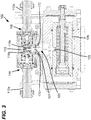
Figure 3 is a cross-sectional view of the control system ofFigure 1 shown coupled to a servo-positon for controlling positioning of a swashplate of a hydraulic pump or motor; -
Figure 4 is a schematic view showing the control system ofFigure 1 coupled to a servo-piston controlling the position of a swashplate of a hydraulic pump/motor; -
Figure 5 is another cross-sectional view of the control system ofFigure 1 showing an angle sensor coupled to a pivot arm of the control system; -
Figure 6 is a perspective view of a pivot shaft of the control system ofFigure 1 ; -
Figure 7 is a perspective view of a pivot axis adjustment sleeve of the control system ofFigure 1 ; -
Figure 8 is a perspective view of an angle sensor of the control system ofFigure 1 ; -
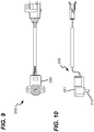
Figure 9 is a plan view of the angle sensor ofFigure 8 ; -
Figure 10 is an elevation view of the angle sensor ofFigure 8 ; -
Figure 11 is a graph plotting flow rate verses signal magnitude for the angle sensor ofFigure 8 ; -
Figure 12 is a perspective view of a further control system in accordance with principles of the present disclosure; -
Figure 13 is a cross-sectional view of the control system ofFigure 12 showing an angle sensor coupled to a pivot arm of the control system; -
Figure 14 is a perspective view of a pivot shaft of the control system ofFigure 12 ; and -
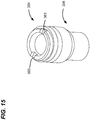
Figure 15 is a perspective view of a pivot axis adjustment sleeve of the control system ofFigure 12 . - Referring to
Figures 1 and2 , acontrol system 102 for a hydraulic axial displacement machine (e.g., seehydraulic machine 100 atFigure 4 ) is schematically depicted. In some non-limiting examples the axial displacement machines described herein include hydraulic motors or hydraulic pumps. Such hydraulic axial displacement machines can be utilized in a wide variety of equipment having a hydraulics system or a hydraulics component, and the present disclosure is not limited to any particular type or types of equipment in which the hydraulic axial displacement machines described herein are implemented. Thecontrol system 102 includes afirst control module 104 and asecond control module 106. In some examples, the first and second control modules are of identical construction and include identical parts. Thefirst control module 104 controls forward motion of a servo-piston 108. Thesecond control module 106 controls reverse motion of the servo-piston 108. - Each
control module spool spool actuator input line charge pressure line piston 108, afeedback piston feedback piston spring control module 104 is active during forward motion of thehydraulic machine 100, and thecontrol module 106 is active during reverse motion of thehydraulic machine 100. In thisexample control system 102, thefeedback pistons spools spool actuators piston 108 is coupled to a swashplate 124 (Figure 4 ) of thehydraulic machine 100. Thepivot arm 122 includes a first portion 123 (e.g., a first end or end portion) positioned between thepistons piston 108. Thepivot arm 122 pivots about apivot axis 127 in concert (e.g., unison) with movement of the servo-piston 108. For example, movement of the servo-piston 108 drives/causes pivotal movement of thepivot arm 122 about thepivot axis 127. - When neither of the
spools solenoid piston charge lines Figure 4 ) in a neutral position. An electrical charging signal is sent to theforward motion solenoid 112a or thereverse motion solenoid 112b, actuating thecorresponding spool solenoid spool pressure input line piston charge line - The charging pressure in the
charge line spool Figure 1 , corresponding to forward or reverse motion, respectively, of themachine 100. - Movement of the servo-
piston 108 causes thepivot arm 122 to pivot aboutaxis 127 such that thefeedback piston feedback spring feedback piston spool solenoid spool feedback spring corresponding feedback piston swashplate 124 relative to its neutral position. - As the charging signal on the
solenoid corresponding spool feedback spring corresponding feedback piston spool spool swashplate 124 to their neutral position. The amount of axial motion of thespool respective feedback piston swashplate 124 relative to the neutral position of theswashplate 124. - The
pivot arm 122 is not in direct contact with eitherspool spool corresponding feedback piston feedback spring feedback piston corresponding feedback spring feedback spring spring coupler spring coupler corresponding spool corresponding feedback spring - The
pivot arm 122 is configured to pivot about thepivot axis 127 in concert with movement of the servo-piston 108. An angular position of thepivot arm 122 is indicative of the angular position of the swashplate. Thepivot axis 127 is defined by apivot shaft 150 coupled to thepivot arm 122 by acap bolt 152. Thepivot arm 122 and thepivot shaft 150 are configured to rotate together about thepivot axis 127. Thepivot axis 127 coincides with a longitudinal centerline of thepivot shaft 150. Thepivot shaft 150 rotatably mounts within a pivotaxis adjustment sleeve 154. For example, ahead 155 of thepivot shaft 150 mounts for rotation within thesleeve 154, ashoulder 157 of thepivot shaft 150 seats on alip 158 of thesleeve 154, and ashank 156 of thepivot shaft 150 extends through an opening in thesleeve 154. Thepivot shaft 150 is eccentric with respect to thesleeve 154. Thesleeve 154 mounts within areceptacle 160 defined by ahousing 161 of thecontrol system 102 which also supports the valve arrangement. Due to the eccentricity of thepivot shaft 150, the location of thepivot axis 127 relative to the valve arrangement and the servo-piston 108 can be adjusted by turning thesleeve 154 about its center axis within thereceptacle 160.Notches 163 in an end of thesleeve 154 can receive a tool used to turn thesleeve 154 within the receptacle. Thepivot axis 127 position can be adjusted to properly center thepivot arm 122 between thepistons axis 127 can be moved in afirst direction 170 to increase spring loading at thefirst control module 104 and reduce spring loading at thesecond control module 106, and the axis can be moved in asecond direction 172 to increase spring loading at thesecond control module 106 and reduce spring loading at thefirst control module 104. Once the loading has been balanced, thesleeve 154 can be locked in the set rotational position by a lateral setscrew 176 that engages a side of thesleeve 154. - The
control system 102 includes an arm angle sensor 200 (seeFigures 1 ,5 and8-10 ), asensor housing 201 of which is depicted as a component coupled to aplate 165 mounted at an exterior surface ofcontrol housing 161. In one example, theangle sensor 200 is a rotator encoder having asensor shaft 210 that rotates about it center axis relative to internal sensing components within thesensor housing 201 which sense the degree of rotation. Thesensor shaft 210 can be rotationally biased by the angle sensor toward a neutral rotational sensing position. Thesensor housing 201 mounts to theplate 165 in a manner that allows a rotational position of thehousing 201 to be rotationally adjusted relative to theplate 165 about the central axis of thesensor shaft 210. For example, thehousing 201 can be secured to theplate 165 by fasteners 220 (e.g., bolts, screws, etc.) that extend throughopenings 222 defined by thehousing 201. Theopenings 222 can be oversized, elongated or otherwise shaped to allow for rotational adjustment of thehousing 201. In the depicted example, theopenings 222 are slots that curve about thesensor shaft 210. Once the housing has been set at a desired rotational position relative to theplate 165, thefasteners 220 can be fully tightened to lock thehousing 201 in the selected rotational position. - The
plate 165 covers thesleeve 154 and thereceptacle 160. Thesensor shaft 210 extends through theplate 165 and engages thepivot shaft 150. The center of thesensor shaft 210 preferably aligns with the center of thepivot shaft 150. Thepivot shaft 150 and thesensor shaft 210 are connected in such manner that they rotate together about thepivot axis 127. Thesensor shaft 210 has an end with an elongate cross-section that fits or mate within a matching receptacle defined in one end of thepivot shaft 150. Thus, as thepivot arm 122 rotates about thepivot axis 127, thepivot shaft 150 and thesensor shaft 210 also rotate about thepivot axis 127. The ability to adjust thesensor housing 201 on theplate 165 allows the angle sensor to be rotationally adjusted such that thesensor shaft 210 is in the neutral position relative to the internal sensing components of the sensor when thepivot arm 122 is in a position corresponding to the swashplate being in the neutral position. In this way, in the event the angle sensor fails, the system can continue to operate under electro-proportional displacement control with mechanical feedback provided by the pivot arm without internal biasing or spring loading within the angle sensor compromising balancing/centering of thepivot arm 122. - The
arm angle sensor 200 is adapted to detect pivoting of the feedback arm and provide signals corresponding to the pivot angle to a main controller. The main controller is configured to compare the sensed pivot angle with the electrical drive command signal (or other drive command signal, e.g., an hydraulic drive command signal) for driving the servo-piston 108. To the extent there is a discrepancy between the sensed pivot angle and the command signal, the main controller is adapted to provide an error correction signal to the appropriate solenoid orother spool actuator Figure 4 ). The controller is thus operatively coupled to thesolenoids solenoids Figure 11 is a graph showing flow verses feedback signal magnitude. The sensor feedback signal magnitude ranges from 0-5 volts. The neutral position of thesensor 200 is set to 2.5 volts. 0-2.5 volts represents feedback in the forward operating mode and 2.5-5.0 volts represents feedback in the reverse operating mode. - In some examples the controller 522 includes, or is operatively coupled to, a processor that executes computer readable instructions stored on a memory, where the execution of the computer-readable instructions causes the controller 522 to provide the control signals needed to correct a discrepancy between a desired and an actual angle of the swashplate and to provide no correction signal when there is no discrepancy or less than a predetermined maximum threshold discrepancy.
- In the depicted example, the
pivot arm 122 is biased between two co-axially aligned valve spools. In other examples, a pivot arm can be spring-biased with respect to valve spools or other valve components that are not co-axially aligned. For example, valve spools can be parallel and side-by side with respect to one another and can each be spring biased against separate portions of a pivot arm as shown by FIG. 18 of PCT International application No.PCT/US2018/000157 , which is hereby incorporated by reference in its entirety. - Referring to
Figures 12-15 , thecontrol system 302 includes many corresponding features and principles of operation as thecontrol system 102 described above, where like parts are referred to with like reference numerals. Consequently, the following description will focus on differences between thecontrol system 302 and thecontrol system 102. - The
plate 365 of thecontrol system 302 is configured to nest in aseat 382 defined by arecess 380 in a wall of the pivotaxis adjustment sleeve 354. The seating ofplate 365 in theseat 382 can provide for improved mechanical alignment between the sensor and thesleeve 354. -
Notches 363 in an end of thesleeve 354 can receive a tool used to turn thesleeve 354 within the receptacle. Thepivot axis 327 position can be adjusted to properly center thepivot arm 122 between the pistons so that balanced loading is ensured between the two modules. - The
sleeve 354 has anextension portion 396 to enhance contact between the internal wall of thesleeve 354 and theshaft 350. Theshaft 350, unlike theshaft 150, does not include a shoulder below the head and, correspondingly, thesleeve 354, unlike thesleeve 154, does not include lip where the shoulder of a shaft might otherwise rest. To restrict vertical movement of theshaft 350 and the feedback link, thecap bolt 352 is elongated along theaxis 327 as compared with thecap bolt 152. - The configuration and arrangement of the
shaft 350, thesleeve 354, thecap bolt 352, and theplate 365 can provide enhanced alignment of these components relative to one another within thesystem 302. - According to a 1st example embodiment, there is provided a control system for controlling an angular position of a swashplate of an axial piston hydraulic pump or motor, the angular position of the swashplate being determined by a servo-piston, the control system comprising: a valve arrangement for providing a charge pressure to the servo-piston which causes the servo-piston to alter the angular position of the swashplate; a pivot arm configured to pivot about a pivot axis in concert with movement of the servo-piston, wherein an angular position of the pivot arm is indicative of the angular position of the swashplate, and wherein the pivot axis is adjustable in position with respect to the valve member and the servo-piston; and a spring for transferring spring load between the pivot arm and a valve member of the valve arrangement.
- According to a 2nd example embodiment, there is provided the 1st example embodiment, further comprising a pivot shaft coupled to the pivot arm, the pivot shaft defining the pivot axis and being adapted to pivot in concert with the pivot arm about the pivot axis, the control system also including a pivot axis adjustment sleeve in which the pivot shaft is rotatably mounted, the pivot axis adjustment being mounted within a receptacle defined by a housing of the valve assembly, the pivot shaft being eccentric with respect to the pivot axis adjustment sleeve such that rotation of the pivot axis adjustment sleeve about its center axis relative to the housing of the valve assembly adjusts the position of the pivot axis with respect to the valve assembly and the servo-piston.
- According to a 3rd example embodiment, there is provided the 2nd example embodiment, wherein the pivot axis adjustment sleeve is configured to be locked at a set rotational position about its center axis relative to the housing of the valve assembly once the pivot axis is in a predefined position.
- According to a 4th example embodiment, there is provided a control system for controlling an angular position of a swashplate of an axial piston hydraulic pump or motor, the angular position of the swashplate being determined by a servo-piston, the control system comprising: a valve arrangement for providing a charge pressure to the servo-piston which causes the servo-piston to alter the angular position of the swashplate; a pivot arm configured to pivot about a pivot axis in concert with movement of the servo-piston, wherein an angular position of the pivot arm is indicative of the angular position of the swashplate; a spring for transferring spring load between the pivot arm and a valve member of the valve arrangement; and an angle sensor for sensing the angular position of the pivot arm, a housing of the angle sensor being angularly adjustable about the pivot axis relative to the pivot arm.
- According to a 5th example embodiment, there is provided the 4th example embodiment, wherein a plate mounts to the housing of the angle sensor, and wherein the angle sensor mounts on the plate.
- According to a 6th example embodiment, there is provided the 5th example embodiment, wherein the angle sensor incudes an angle sensing shaft that extends through the plate and engages a pivot shaft coupled to the pivot arm such that the angle sensing shaft and the pivot shaft are configured to rotate together about a pivot axis.
Claims (14)
- A control system for controlling an angular position of a swashplate of an axial piston hydraulic pump or motor, the angular position of the swashplate being determined by a servo-piston, the control system comprising:a valve arrangement for providing a charge pressure to the servo-piston which causes the servo-piston to alter the angular position of the swashplate;a pivot arm configured to pivot about a pivot axis in concert with movement of the servo-piston, wherein an angular position of the pivot arm is indicative of the angular position of the swashplate, and wherein the pivot axis is adjustable in position with respect to the valve member and the servo-piston;a spring for transferring spring load between the pivot arm and a valve member of the valve arrangement; andan angle sensor for sensing the angular position of the pivot arm, a housing of the angle sensor being angularly adjustable about the pivot axis relative to the pivot arm.
- The control system of claim 1, further comprising a pivot shaft coupled to the pivot arm, the pivot shaft defining the pivot axis and being adapted to pivot in concert with the pivot arm about the pivot axis, the control system also including a pivot axis adjustment sleeve in which the pivot shaft is rotatably mounted, the pivot axis adjustment being mounted within a receptacle defined by a housing of the valve assembly, the pivot shaft being eccentric with respect to the pivot axis adjustment sleeve such that rotation of the pivot axis adjustment sleeve about its center axis relative to the housing of the valve assembly adjusts the position of the pivot axis with respect to the valve assembly and the servo-piston.
- The control system of claim 2, wherein the pivot axis adjustment sleeve is configured to be locked at a set rotational position about its center axis relative to the housing of the valve assembly once the pivot axis is in a predefined position.
- The control system of claim 3, wherein the pivot axis adjustment sleeve is locked in the set rotational position by a locking screw that laterally engages the pivot axis adjustment sleeve.
- The control system of claim 3, wherein a plate mounts to the housing of the angle sensor over the receptacle for the pivot axis adjustment sleeve, and wherein the angle sensor mounts on the plate.
- The control system of claim 5, wherein the angle sensor incudes an angle sensing shaft that extends through the plate and engages the pivot shaft such that the angle sensing shaft and the pivot shaft are configured to rotate together about the pivot axis.
- The control system of claim 6, wherein the pivot shaft defines a receiver at one end for receiving an end of the angle sensing shaft, and wherein the angle sensing shaft and the receiver have matching non-circular cross-sectional shapes.
- The control system of claim 6, wherein the sensor housing mounts to the plate, and wherein the sensor housing is rotationally adjustable relative to the plate about the pivot axis, and wherein the sensor housing and related internal sensing circuitry rotates relative to the angle sensing shaft when the sensor housing is rotationally adjusted to allow the angle sensor to be set at a neutral rotational sensing position relative to the pivot arm when the pivot arm is in a positon corresponding to the neutral position of the swashplate.
- The control system of claim 8, wherein the sensor housing mounts to the plate with fasteners, wherein the sensor housing defines fastener openings through which the fasteners extend, and wherein the fastener openings are sized and shaped to allow for a limited range of rotational movement of the sensor housing relative to the plate about the pivot axis prior to full tightening of the fasteners
- The control system of claim 9, wherein full tightening of the fasteners rotationally locks the sensor housing in place relative to the plate.
- The control system of claim 1, wherein the valve member includes a valve spool that is moved by a solenoid.
- The control system of any of claim 1, wherein the valve member is a first valve spool, wherein the valve arrangement includes a second valve spool co-axially aligned with the first valve spool along a valve axis, wherein first and second solenoids respectively move the first and second valve spools along the valve axis, wherein a first end of the pivot arm is positioned between the first and second valve spools, wherein a second end of the pivot arm engages the servo-piston, wherein the pivot axis is positioned between the first and second ends of the pivot arm, wherein actuation of the first solenoid causes the servo-piston to operate the pump or motor in a forward mode, and wherein actuation of the second solenoid causes the servo-piston to operate the pump or motor in a reverse mode.
- The control system of claim 12, wherein the position of the pivot axis is adjusted to move the pivot arm either toward the first valve spool or toward the second valve spool to set the pivot arm in a position in which balanced flow characteristics are achieved for both forward and rearward operation of the pump or motor.
- The control system of claim 13, further comprising a first piston and a first spring between the first end of the pivot arm and the first valve spool, and a second piston and a second spring between the first end of the pivot arm and the second valve spool.
Applications Claiming Priority (1)
| Application Number | Priority Date | Filing Date | Title |
|---|---|---|---|
| IN201911003901 | 2019-01-31 |
Publications (3)
| Publication Number | Publication Date |
|---|---|
| EP3690229A1 true EP3690229A1 (en) | 2020-08-05 |
| EP3690229B1 EP3690229B1 (en) | 2021-10-06 |
| EP3690229B8 EP3690229B8 (en) | 2021-11-24 |
Family
ID=69375279
Family Applications (1)
| Application Number | Title | Priority Date | Filing Date |
|---|---|---|---|
| EP20154209.9A Not-in-force EP3690229B8 (en) | 2019-01-31 | 2020-01-28 | Displacement control with angle sensor adjustment |
Country Status (3)
| Country | Link |
|---|---|
| US (1) | US11608825B2 (en) |
| EP (1) | EP3690229B8 (en) |
| CN (1) | CN111502942B (en) |
Cited By (1)
| Publication number | Priority date | Publication date | Assignee | Title |
|---|---|---|---|---|
| CN114352533A (en) * | 2022-01-24 | 2022-04-15 | 南通市红星空压机配件制造有限公司 | Control method for electric air inlet valve of movable air compressor |
Families Citing this family (5)
| Publication number | Priority date | Publication date | Assignee | Title |
|---|---|---|---|---|
| US11731688B2 (en) * | 2019-06-04 | 2023-08-22 | Cnh Industrial America Llc | Differential steering control vehicle, system and method |
| IT202000005020A1 (en) * | 2020-03-09 | 2021-09-09 | Pmp Pro Mec S P A | VARIABLE DISPLACEMENT HYDRAULIC PUMP |
| CN112283432B (en) * | 2020-11-25 | 2025-12-02 | 力源液压(苏州)有限公司 | A hydraulic system, a closed-loop piston pump, and a bidirectional electro-proportional displacement control device. |
| IT202200015621A1 (en) * | 2022-07-25 | 2024-01-25 | Casappa Spa | VARIABLE DISPLACEMENT VOLUMETRIC MACHINE |
| DE202022106185U1 (en) * | 2022-11-03 | 2024-02-06 | Dana Motion Systems Italia S.R.L. | Piston arrangement |
Citations (8)
| Publication number | Priority date | Publication date | Assignee | Title |
|---|---|---|---|---|
| US4375942A (en) * | 1981-04-21 | 1983-03-08 | Dynes/Rivett Inc. | Tilting cam, rotating barrel pump |
| US20040115065A1 (en) * | 2002-12-12 | 2004-06-17 | Caterpillar Inc. | Sensor for a variable displacement pump |
| US20050084387A1 (en) * | 2003-10-15 | 2005-04-21 | Sauer-Danfoss Inc. | Control system for hydrostatic pump |
| US7121188B2 (en) | 2004-07-09 | 2006-10-17 | Sauer-Danfoss Inc. | Axial piston machine having a device for the electrically proportional adjustment of its volumetric displacement |
| US7171997B2 (en) | 2003-05-14 | 2007-02-06 | Hitachi Koki Co., Ltd. | Portable electric router having radial fan |
| EP1892413A1 (en) * | 2005-05-30 | 2008-02-27 | Hitachi Construction Machinery Co., Ltd. | Variable displacement swash plate type hydraulic rotary machine |
| KR20120060441A (en) * | 2010-12-02 | 2012-06-12 | 두산모트롤주식회사 | The regulator for the hydraulic pump of the excavator |
| US20160348654A1 (en) * | 2015-05-29 | 2016-12-01 | Kanzaki Kokyukoki Mfg. Co., Ltd. | Hydraulic pump |
Family Cites Families (13)
| Publication number | Priority date | Publication date | Assignee | Title |
|---|---|---|---|---|
| US3429225A (en) | 1966-06-09 | 1969-02-25 | Abex Corp | Electrohydraulic displacement control with mechanical feedback |
| DE3143539A1 (en) | 1981-11-03 | 1983-05-11 | Linde Ag, 6200 Wiesbaden | CONTROL DEVICE FOR A CONTINUOUSLY ADJUSTABLE, PREFERABLY HYDROSTATIC GEARBOX |
| US4456434A (en) | 1982-03-01 | 1984-06-26 | Vickers, Incorporated | Power transmission |
| DE10220889C5 (en) | 2002-05-10 | 2009-05-28 | Brueninghaus Hydromatik Gmbh | Adjustment device for hydrostatic piston machines |
| JP4113414B2 (en) | 2002-10-29 | 2008-07-09 | 新キャタピラー三菱株式会社 | Pump device |
| KR100506640B1 (en) | 2003-01-22 | 2005-08-10 | 한국기계연구원 | Servo regulator of variable displacement swash plate type piston pump controlled in positive-negative direction |
| JP4845026B2 (en) | 2006-09-21 | 2011-12-28 | キャタピラー エス エー アール エル | Swash plate control device for variable displacement pump |
| US8397759B2 (en) | 2008-03-04 | 2013-03-19 | Keihin Corporation | Electromagnetic spool valve |
| JP4997163B2 (en) | 2008-03-31 | 2012-08-08 | カヤバ工業株式会社 | Servo regulator |
| DE102008048507A1 (en) * | 2008-09-23 | 2010-03-25 | Robert Bosch Gmbh | Device with adjustable backlash for a control device |
| DE102016200234A1 (en) * | 2016-01-12 | 2017-07-13 | Danfoss Power Solutions Gmbh & Co. Ohg | INCLINED DISK ANGLE SENSOR |
| JP6912907B2 (en) * | 2017-03-13 | 2021-08-04 | Kyb株式会社 | Servo regulator |
| WO2019035891A1 (en) | 2017-08-18 | 2019-02-21 | Eaton Intelligent Power Limited | Control systems for hydraulic axial displacement machines |
-
2020
- 2020-01-28 EP EP20154209.9A patent/EP3690229B8/en not_active Not-in-force
- 2020-01-29 US US16/776,172 patent/US11608825B2/en active Active
- 2020-02-03 CN CN202010079438.9A patent/CN111502942B/en not_active Expired - Fee Related
Patent Citations (8)
| Publication number | Priority date | Publication date | Assignee | Title |
|---|---|---|---|---|
| US4375942A (en) * | 1981-04-21 | 1983-03-08 | Dynes/Rivett Inc. | Tilting cam, rotating barrel pump |
| US20040115065A1 (en) * | 2002-12-12 | 2004-06-17 | Caterpillar Inc. | Sensor for a variable displacement pump |
| US7171997B2 (en) | 2003-05-14 | 2007-02-06 | Hitachi Koki Co., Ltd. | Portable electric router having radial fan |
| US20050084387A1 (en) * | 2003-10-15 | 2005-04-21 | Sauer-Danfoss Inc. | Control system for hydrostatic pump |
| US7121188B2 (en) | 2004-07-09 | 2006-10-17 | Sauer-Danfoss Inc. | Axial piston machine having a device for the electrically proportional adjustment of its volumetric displacement |
| EP1892413A1 (en) * | 2005-05-30 | 2008-02-27 | Hitachi Construction Machinery Co., Ltd. | Variable displacement swash plate type hydraulic rotary machine |
| KR20120060441A (en) * | 2010-12-02 | 2012-06-12 | 두산모트롤주식회사 | The regulator for the hydraulic pump of the excavator |
| US20160348654A1 (en) * | 2015-05-29 | 2016-12-01 | Kanzaki Kokyukoki Mfg. Co., Ltd. | Hydraulic pump |
Cited By (2)
| Publication number | Priority date | Publication date | Assignee | Title |
|---|---|---|---|---|
| CN114352533A (en) * | 2022-01-24 | 2022-04-15 | 南通市红星空压机配件制造有限公司 | Control method for electric air inlet valve of movable air compressor |
| CN114352533B (en) * | 2022-01-24 | 2023-11-21 | 南通市红星空压机配件制造有限公司 | Control method for electric air inlet valve of mobile air compressor |
Also Published As
| Publication number | Publication date |
|---|---|
| CN111502942A (en) | 2020-08-07 |
| US11608825B2 (en) | 2023-03-21 |
| EP3690229B8 (en) | 2021-11-24 |
| EP3690229B1 (en) | 2021-10-06 |
| US20200248553A1 (en) | 2020-08-06 |
| CN111502942B (en) | 2023-09-19 |
Similar Documents
| Publication | Publication Date | Title |
|---|---|---|
| EP3690229B1 (en) | Displacement control with angle sensor adjustment | |
| US5953978A (en) | Hydraulic power steering system | |
| KR101069477B1 (en) | Pump control unit of construction machinery | |
| US6179082B1 (en) | Hydraulic steering apparatus and method | |
| JP3951004B2 (en) | Hydrostatic type axial piston machine | |
| JP4146899B2 (en) | Rolling stabilization device for powered vehicles | |
| US20160376769A1 (en) | Hydraulic drive system for working machine including track device of crawler type | |
| EP2718508B1 (en) | Velocity control for hydraulic control system | |
| US6298940B1 (en) | Power steering system for motor vehicles | |
| US6843341B2 (en) | Method of controlling a power steering system | |
| KR930002476B1 (en) | Hydraulic Drive | |
| US10539162B2 (en) | Hydraulic system for work machine | |
| KR101210733B1 (en) | The regulator for the hydraulic pump of the excavator | |
| US8210206B2 (en) | Dual redundant servovalve | |
| US20130239796A1 (en) | Hydrostatic axial piston machine | |
| JPH05332304A (en) | Hydraulic circuit of 4-position closed center switching valve with pressure proportional control valve | |
| JP2015040604A (en) | Hydraulic control device of work machine | |
| US8943949B2 (en) | Neutral setting apparatus of an adjustable hydraulic machine | |
| JPWO2019106831A1 (en) | Work machine and control method of work machine | |
| CN110088469B (en) | Manual displacement control device for axial piston pump | |
| US6684634B1 (en) | Swash plate angle control mechanism of hydraulic continuously variable transmission | |
| US11181154B2 (en) | Control systems for hydraulic axial displacement machines | |
| CN110792568B (en) | Torque control and feedback device | |
| EP0112791B1 (en) | Automatic pressure setting adjustment for pressure compensated pumps | |
| CN115087593A (en) | Steering system |
Legal Events
| Date | Code | Title | Description |
|---|---|---|---|
| PUAI | Public reference made under article 153(3) epc to a published international application that has entered the european phase |
Free format text: ORIGINAL CODE: 0009012 |
|
| STAA | Information on the status of an ep patent application or granted ep patent |
Free format text: STATUS: REQUEST FOR EXAMINATION WAS MADE |
|
| 17P | Request for examination filed |
Effective date: 20200128 |
|
| AK | Designated contracting states |
Kind code of ref document: A1 Designated state(s): AL AT BE BG CH CY CZ DE DK EE ES FI FR GB GR HR HU IE IS IT LI LT LU LV MC MK MT NL NO PL PT RO RS SE SI SK SM TR |
|
| AX | Request for extension of the european patent |
Extension state: BA ME |
|
| GRAP | Despatch of communication of intention to grant a patent |
Free format text: ORIGINAL CODE: EPIDOSNIGR1 |
|
| STAA | Information on the status of an ep patent application or granted ep patent |
Free format text: STATUS: GRANT OF PATENT IS INTENDED |
|
| INTG | Intention to grant announced |
Effective date: 20210507 |
|
| GRAS | Grant fee paid |
Free format text: ORIGINAL CODE: EPIDOSNIGR3 |
|
| GRAA | (expected) grant |
Free format text: ORIGINAL CODE: 0009210 |
|
| STAA | Information on the status of an ep patent application or granted ep patent |
Free format text: STATUS: THE PATENT HAS BEEN GRANTED |
|
| AK | Designated contracting states |
Kind code of ref document: B1 Designated state(s): AL AT BE BG CH CY CZ DE DK EE ES FI FR GB GR HR HU IE IS IT LI LT LU LV MC MK MT NL NO PL PT RO RS SE SI SK SM TR |
|
| REG | Reference to a national code |
Ref country code: GB Ref legal event code: FG4D |
|
| REG | Reference to a national code |
Ref country code: CH Ref legal event code: EP Ref country code: AT Ref legal event code: REF Ref document number: 1436444 Country of ref document: AT Kind code of ref document: T Effective date: 20211015 |
|
| REG | Reference to a national code |
Ref country code: DE Ref legal event code: R096 Ref document number: 602020000654 Country of ref document: DE |
|
| REG | Reference to a national code |
Ref country code: DE Ref legal event code: R081 Ref document number: 602020000654 Country of ref document: DE Owner name: DANFOSS POWER SOLUTIONS II TECHNOLOGY A/S, DK Free format text: FORMER OWNER: EATON INTELLIGENT POWER LIMITED, DUBLIN, IE |
|
| REG | Reference to a national code |
Ref country code: IE Ref legal event code: FG4D |
|
| REG | Reference to a national code |
Ref country code: CH Ref legal event code: PK Free format text: BERICHTIGUNG B8 |
|
| RAP2 | Party data changed (patent owner data changed or rights of a patent transferred) |
Owner name: DANFOSS POWER SOLUTIONS II TECHNOLOGY A/S |
|
| REG | Reference to a national code |
Ref country code: LT Ref legal event code: MG9D |
|
| REG | Reference to a national code |
Ref country code: NL Ref legal event code: MP Effective date: 20211006 |
|
| REG | Reference to a national code |
Ref country code: AT Ref legal event code: MK05 Ref document number: 1436444 Country of ref document: AT Kind code of ref document: T Effective date: 20211006 |
|
| PG25 | Lapsed in a contracting state [announced via postgrant information from national office to epo] |
Ref country code: RS Free format text: LAPSE BECAUSE OF FAILURE TO SUBMIT A TRANSLATION OF THE DESCRIPTION OR TO PAY THE FEE WITHIN THE PRESCRIBED TIME-LIMIT Effective date: 20211006 Ref country code: LT Free format text: LAPSE BECAUSE OF FAILURE TO SUBMIT A TRANSLATION OF THE DESCRIPTION OR TO PAY THE FEE WITHIN THE PRESCRIBED TIME-LIMIT Effective date: 20211006 Ref country code: FI Free format text: LAPSE BECAUSE OF FAILURE TO SUBMIT A TRANSLATION OF THE DESCRIPTION OR TO PAY THE FEE WITHIN THE PRESCRIBED TIME-LIMIT Effective date: 20211006 Ref country code: BG Free format text: LAPSE BECAUSE OF FAILURE TO SUBMIT A TRANSLATION OF THE DESCRIPTION OR TO PAY THE FEE WITHIN THE PRESCRIBED TIME-LIMIT Effective date: 20220106 Ref country code: AT Free format text: LAPSE BECAUSE OF FAILURE TO SUBMIT A TRANSLATION OF THE DESCRIPTION OR TO PAY THE FEE WITHIN THE PRESCRIBED TIME-LIMIT Effective date: 20211006 |
|
| PG25 | Lapsed in a contracting state [announced via postgrant information from national office to epo] |
Ref country code: IS Free format text: LAPSE BECAUSE OF FAILURE TO SUBMIT A TRANSLATION OF THE DESCRIPTION OR TO PAY THE FEE WITHIN THE PRESCRIBED TIME-LIMIT Effective date: 20220206 Ref country code: SK Free format text: LAPSE BECAUSE OF FAILURE TO SUBMIT A TRANSLATION OF THE DESCRIPTION OR TO PAY THE FEE WITHIN THE PRESCRIBED TIME-LIMIT Effective date: 20211006 Ref country code: SE Free format text: LAPSE BECAUSE OF FAILURE TO SUBMIT A TRANSLATION OF THE DESCRIPTION OR TO PAY THE FEE WITHIN THE PRESCRIBED TIME-LIMIT Effective date: 20211006 Ref country code: PT Free format text: LAPSE BECAUSE OF FAILURE TO SUBMIT A TRANSLATION OF THE DESCRIPTION OR TO PAY THE FEE WITHIN THE PRESCRIBED TIME-LIMIT Effective date: 20220207 Ref country code: PL Free format text: LAPSE BECAUSE OF FAILURE TO SUBMIT A TRANSLATION OF THE DESCRIPTION OR TO PAY THE FEE WITHIN THE PRESCRIBED TIME-LIMIT Effective date: 20211006 Ref country code: NO Free format text: LAPSE BECAUSE OF FAILURE TO SUBMIT A TRANSLATION OF THE DESCRIPTION OR TO PAY THE FEE WITHIN THE PRESCRIBED TIME-LIMIT Effective date: 20220106 Ref country code: NL Free format text: LAPSE BECAUSE OF FAILURE TO SUBMIT A TRANSLATION OF THE DESCRIPTION OR TO PAY THE FEE WITHIN THE PRESCRIBED TIME-LIMIT Effective date: 20211006 Ref country code: LV Free format text: LAPSE BECAUSE OF FAILURE TO SUBMIT A TRANSLATION OF THE DESCRIPTION OR TO PAY THE FEE WITHIN THE PRESCRIBED TIME-LIMIT Effective date: 20211006 Ref country code: HR Free format text: LAPSE BECAUSE OF FAILURE TO SUBMIT A TRANSLATION OF THE DESCRIPTION OR TO PAY THE FEE WITHIN THE PRESCRIBED TIME-LIMIT Effective date: 20211006 Ref country code: GR Free format text: LAPSE BECAUSE OF FAILURE TO SUBMIT A TRANSLATION OF THE DESCRIPTION OR TO PAY THE FEE WITHIN THE PRESCRIBED TIME-LIMIT Effective date: 20220107 Ref country code: ES Free format text: LAPSE BECAUSE OF FAILURE TO SUBMIT A TRANSLATION OF THE DESCRIPTION OR TO PAY THE FEE WITHIN THE PRESCRIBED TIME-LIMIT Effective date: 20211006 |
|
| REG | Reference to a national code |
Ref country code: DE Ref legal event code: R097 Ref document number: 602020000654 Country of ref document: DE |
|
| PG25 | Lapsed in a contracting state [announced via postgrant information from national office to epo] |
Ref country code: SM Free format text: LAPSE BECAUSE OF FAILURE TO SUBMIT A TRANSLATION OF THE DESCRIPTION OR TO PAY THE FEE WITHIN THE PRESCRIBED TIME-LIMIT Effective date: 20211006 Ref country code: RO Free format text: LAPSE BECAUSE OF FAILURE TO SUBMIT A TRANSLATION OF THE DESCRIPTION OR TO PAY THE FEE WITHIN THE PRESCRIBED TIME-LIMIT Effective date: 20211006 Ref country code: EE Free format text: LAPSE BECAUSE OF FAILURE TO SUBMIT A TRANSLATION OF THE DESCRIPTION OR TO PAY THE FEE WITHIN THE PRESCRIBED TIME-LIMIT Effective date: 20211006 Ref country code: DK Free format text: LAPSE BECAUSE OF FAILURE TO SUBMIT A TRANSLATION OF THE DESCRIPTION OR TO PAY THE FEE WITHIN THE PRESCRIBED TIME-LIMIT Effective date: 20211006 Ref country code: CZ Free format text: LAPSE BECAUSE OF FAILURE TO SUBMIT A TRANSLATION OF THE DESCRIPTION OR TO PAY THE FEE WITHIN THE PRESCRIBED TIME-LIMIT Effective date: 20211006 |
|
| PLBE | No opposition filed within time limit |
Free format text: ORIGINAL CODE: 0009261 |
|
| STAA | Information on the status of an ep patent application or granted ep patent |
Free format text: STATUS: NO OPPOSITION FILED WITHIN TIME LIMIT |
|
| PG25 | Lapsed in a contracting state [announced via postgrant information from national office to epo] |
Ref country code: MC Free format text: LAPSE BECAUSE OF FAILURE TO SUBMIT A TRANSLATION OF THE DESCRIPTION OR TO PAY THE FEE WITHIN THE PRESCRIBED TIME-LIMIT Effective date: 20211006 |
|
| 26N | No opposition filed |
Effective date: 20220707 |
|
| REG | Reference to a national code |
Ref country code: BE Ref legal event code: MM Effective date: 20220131 |
|
| PG25 | Lapsed in a contracting state [announced via postgrant information from national office to epo] |
Ref country code: LU Free format text: LAPSE BECAUSE OF NON-PAYMENT OF DUE FEES Effective date: 20220128 Ref country code: AL Free format text: LAPSE BECAUSE OF FAILURE TO SUBMIT A TRANSLATION OF THE DESCRIPTION OR TO PAY THE FEE WITHIN THE PRESCRIBED TIME-LIMIT Effective date: 20211006 |
|
| PG25 | Lapsed in a contracting state [announced via postgrant information from national office to epo] |
Ref country code: SI Free format text: LAPSE BECAUSE OF FAILURE TO SUBMIT A TRANSLATION OF THE DESCRIPTION OR TO PAY THE FEE WITHIN THE PRESCRIBED TIME-LIMIT Effective date: 20211006 Ref country code: BE Free format text: LAPSE BECAUSE OF NON-PAYMENT OF DUE FEES Effective date: 20220131 |
|
| PG25 | Lapsed in a contracting state [announced via postgrant information from national office to epo] |
Ref country code: IE Free format text: LAPSE BECAUSE OF NON-PAYMENT OF DUE FEES Effective date: 20220128 |
|
| P01 | Opt-out of the competence of the unified patent court (upc) registered |
Effective date: 20230617 |
|
| REG | Reference to a national code |
Ref country code: CH Ref legal event code: PL |
|
| PG25 | Lapsed in a contracting state [announced via postgrant information from national office to epo] |
Ref country code: LI Free format text: LAPSE BECAUSE OF NON-PAYMENT OF DUE FEES Effective date: 20230131 Ref country code: CH Free format text: LAPSE BECAUSE OF NON-PAYMENT OF DUE FEES Effective date: 20230131 |
|
| REG | Reference to a national code |
Ref country code: GB Ref legal event code: 732E Free format text: REGISTERED BETWEEN 20231005 AND 20231011 |
|
| PGFP | Annual fee paid to national office [announced via postgrant information from national office to epo] |
Ref country code: GB Payment date: 20231207 Year of fee payment: 5 |
|
| PGFP | Annual fee paid to national office [announced via postgrant information from national office to epo] |
Ref country code: FR Payment date: 20231222 Year of fee payment: 5 |
|
| PG25 | Lapsed in a contracting state [announced via postgrant information from national office to epo] |
Ref country code: MK Free format text: LAPSE BECAUSE OF FAILURE TO SUBMIT A TRANSLATION OF THE DESCRIPTION OR TO PAY THE FEE WITHIN THE PRESCRIBED TIME-LIMIT Effective date: 20211006 Ref country code: CY Free format text: LAPSE BECAUSE OF FAILURE TO SUBMIT A TRANSLATION OF THE DESCRIPTION OR TO PAY THE FEE WITHIN THE PRESCRIBED TIME-LIMIT Effective date: 20211006 |
|
| PGFP | Annual fee paid to national office [announced via postgrant information from national office to epo] |
Ref country code: DE Payment date: 20231205 Year of fee payment: 5 |
|
| PG25 | Lapsed in a contracting state [announced via postgrant information from national office to epo] |
Ref country code: HU Free format text: LAPSE BECAUSE OF FAILURE TO SUBMIT A TRANSLATION OF THE DESCRIPTION OR TO PAY THE FEE WITHIN THE PRESCRIBED TIME-LIMIT; INVALID AB INITIO Effective date: 20200128 |
|
| PGFP | Annual fee paid to national office [announced via postgrant information from national office to epo] |
Ref country code: IT Payment date: 20231212 Year of fee payment: 5 |
|
| PG25 | Lapsed in a contracting state [announced via postgrant information from national office to epo] |
Ref country code: TR Free format text: LAPSE BECAUSE OF FAILURE TO SUBMIT A TRANSLATION OF THE DESCRIPTION OR TO PAY THE FEE WITHIN THE PRESCRIBED TIME-LIMIT Effective date: 20211006 |
|
| PG25 | Lapsed in a contracting state [announced via postgrant information from national office to epo] |
Ref country code: MT Free format text: LAPSE BECAUSE OF FAILURE TO SUBMIT A TRANSLATION OF THE DESCRIPTION OR TO PAY THE FEE WITHIN THE PRESCRIBED TIME-LIMIT Effective date: 20211006 |
|
| REG | Reference to a national code |
Ref country code: DE Ref legal event code: R119 Ref document number: 602020000654 Country of ref document: DE |
|
| GBPC | Gb: european patent ceased through non-payment of renewal fee |
Effective date: 20250128 |
|
| PG25 | Lapsed in a contracting state [announced via postgrant information from national office to epo] |
Ref country code: DE Free format text: LAPSE BECAUSE OF NON-PAYMENT OF DUE FEES Effective date: 20250801 |
|
| PG25 | Lapsed in a contracting state [announced via postgrant information from national office to epo] |
Ref country code: GB Free format text: LAPSE BECAUSE OF NON-PAYMENT OF DUE FEES Effective date: 20250128 |
|
| PG25 | Lapsed in a contracting state [announced via postgrant information from national office to epo] |
Ref country code: FR Free format text: LAPSE BECAUSE OF NON-PAYMENT OF DUE FEES Effective date: 20250131 |
|
| PG25 | Lapsed in a contracting state [announced via postgrant information from national office to epo] |
Ref country code: IT Free format text: LAPSE BECAUSE OF NON-PAYMENT OF DUE FEES Effective date: 20250128 |