EP3689829B1 - Anaerobic waste water purification tower - Google Patents
Anaerobic waste water purification tower Download PDFInfo
- Publication number
- EP3689829B1 EP3689829B1 EP19154556.5A EP19154556A EP3689829B1 EP 3689829 B1 EP3689829 B1 EP 3689829B1 EP 19154556 A EP19154556 A EP 19154556A EP 3689829 B1 EP3689829 B1 EP 3689829B1
- Authority
- EP
- European Patent Office
- Prior art keywords
- gas
- waste water
- reactor
- sludge
- purification tower
- Prior art date
- Legal status (The legal status is an assumption and is not a legal conclusion. Google has not performed a legal analysis and makes no representation as to the accuracy of the status listed.)
- Active
Links
- 239000002351 wastewater Substances 0.000 title claims description 46
- 238000000746 purification Methods 0.000 title claims description 22
- 239000007789 gas Substances 0.000 claims description 123
- 239000010802 sludge Substances 0.000 claims description 62
- XLYOFNOQVPJJNP-UHFFFAOYSA-N water Substances O XLYOFNOQVPJJNP-UHFFFAOYSA-N 0.000 claims description 42
- 241000446313 Lamella Species 0.000 claims description 35
- 238000000926 separation method Methods 0.000 claims description 11
- 238000005498 polishing Methods 0.000 claims description 8
- 239000011343 solid material Substances 0.000 claims description 3
- 238000004064 recycling Methods 0.000 claims 1
- 239000012071 phase Substances 0.000 description 19
- 238000002156 mixing Methods 0.000 description 11
- 230000000694 effects Effects 0.000 description 6
- 239000003344 environmental pollutant Substances 0.000 description 5
- 238000004519 manufacturing process Methods 0.000 description 5
- 231100000719 pollutant Toxicity 0.000 description 5
- 230000005484 gravity Effects 0.000 description 4
- 238000009434 installation Methods 0.000 description 4
- VNWKTOKETHGBQD-UHFFFAOYSA-N methane Chemical compound C VNWKTOKETHGBQD-UHFFFAOYSA-N 0.000 description 4
- 238000013461 design Methods 0.000 description 3
- 239000007788 liquid Substances 0.000 description 3
- 244000005700 microbiome Species 0.000 description 3
- 239000000203 mixture Substances 0.000 description 3
- 239000007787 solid Substances 0.000 description 3
- 241000894006 Bacteria Species 0.000 description 2
- 230000001133 acceleration Effects 0.000 description 2
- 238000000605 extraction Methods 0.000 description 2
- 239000012530 fluid Substances 0.000 description 2
- 238000000034 method Methods 0.000 description 2
- 239000002957 persistent organic pollutant Substances 0.000 description 2
- 238000005191 phase separation Methods 0.000 description 2
- 239000008213 purified water Substances 0.000 description 2
- 238000009280 upflow anaerobic sludge blanket technology Methods 0.000 description 2
- 238000004065 wastewater treatment Methods 0.000 description 2
- 241000203069 Archaea Species 0.000 description 1
- 230000006978 adaptation Effects 0.000 description 1
- 230000001174 ascending effect Effects 0.000 description 1
- QVGXLLKOCUKJST-UHFFFAOYSA-N atomic oxygen Chemical compound [O] QVGXLLKOCUKJST-UHFFFAOYSA-N 0.000 description 1
- 230000015556 catabolic process Effects 0.000 description 1
- 230000002301 combined effect Effects 0.000 description 1
- 238000000354 decomposition reaction Methods 0.000 description 1
- 230000003247 decreasing effect Effects 0.000 description 1
- 238000006731 degradation reaction Methods 0.000 description 1
- 230000029087 digestion Effects 0.000 description 1
- 238000007865 diluting Methods 0.000 description 1
- 238000005516 engineering process Methods 0.000 description 1
- 238000005243 fluidization Methods 0.000 description 1
- 239000008187 granular material Substances 0.000 description 1
- 239000012535 impurity Substances 0.000 description 1
- 229910010272 inorganic material Inorganic materials 0.000 description 1
- 239000011147 inorganic material Substances 0.000 description 1
- 239000007791 liquid phase Substances 0.000 description 1
- 230000014759 maintenance of location Effects 0.000 description 1
- 238000005259 measurement Methods 0.000 description 1
- 239000008239 natural water Substances 0.000 description 1
- 239000001301 oxygen Substances 0.000 description 1
- 229910052760 oxygen Inorganic materials 0.000 description 1
- 239000002245 particle Substances 0.000 description 1
- 239000013618 particulate matter Substances 0.000 description 1
- 238000011160 research Methods 0.000 description 1
- 230000000717 retained effect Effects 0.000 description 1
- 238000004062 sedimentation Methods 0.000 description 1
- 239000007790 solid phase Substances 0.000 description 1
- 239000000725 suspension Substances 0.000 description 1
- 230000002195 synergetic effect Effects 0.000 description 1
- 238000012546 transfer Methods 0.000 description 1
Images


Classifications
-
- C—CHEMISTRY; METALLURGY
- C02—TREATMENT OF WATER, WASTE WATER, SEWAGE, OR SLUDGE
- C02F—TREATMENT OF WATER, WASTE WATER, SEWAGE, OR SLUDGE
- C02F3/00—Biological treatment of water, waste water, or sewage
- C02F3/28—Anaerobic digestion processes
- C02F3/2846—Anaerobic digestion processes using upflow anaerobic sludge blanket [UASB] reactors
-
- C—CHEMISTRY; METALLURGY
- C02—TREATMENT OF WATER, WASTE WATER, SEWAGE, OR SLUDGE
- C02F—TREATMENT OF WATER, WASTE WATER, SEWAGE, OR SLUDGE
- C02F3/00—Biological treatment of water, waste water, or sewage
- C02F3/28—Anaerobic digestion processes
- C02F3/2866—Particular arrangements for anaerobic reactors
- C02F3/2873—Particular arrangements for anaerobic reactors with internal draft tube circulation
-
- C—CHEMISTRY; METALLURGY
- C02—TREATMENT OF WATER, WASTE WATER, SEWAGE, OR SLUDGE
- C02F—TREATMENT OF WATER, WASTE WATER, SEWAGE, OR SLUDGE
- C02F2203/00—Apparatus and plants for the biological treatment of water, waste water or sewage
- C02F2203/006—Apparatus and plants for the biological treatment of water, waste water or sewage details of construction, e.g. specially adapted seals, modules, connections
Definitions
- the settlers are designed as up-side-down gutters with vertical side walls and are arranged closed to each other with a gap between them to allow the up-flow of water, along with some of the gas.
- the gas bubbles having an ascending motion, are entrapped below the settler (gas hood) and guided along the settler (gas hood), towards a central extraction channel 6.
- the gas bubbles are also conveying sludge and their motion ensure the mixing of the sludge.
- the settlers also have the function to separate the sludge from the gas bubbles before they are extracted, the separated sludge can then move back down into the active zone, owing to gravity.
- the sludge reactor of the anaerobic waste water purification tower of the invention can further comprise, above the first set of three phase separating means:
Description
- The invention relates to the field of anaerobic water treatment, and in particular to one new anaerobic waste water purification tower.
- Industries generating contaminated waste water may need to proceed to a purification of their waste water before releasing it to further treatment processes or to proceed to a sufficient purification to be allowed to release it into the natural water cycle.
- A common convenient, low foot-print water treatment unit is an anaerobic waste water treatment reactor, and in particular a UASB, a subtype of a fluidized bed reactor. In such towers, waste water is injected at the bottom of the reactor, in which a blanket of granular sludge of micro-organisms, each granule being constituted in several layers, constituted by a consortium of different kinds of micro-organisms, archaea, bacteria, among others, is maintained in suspension owing to a combination of the upward flow and the settling effect of gravity. Next to water (liquid phase) and sludge (solid phase) biogas (gas phase) is also present. Biogas is produced by the bacteria upon decomposition of the organic impurities dissolved in the waste water.
- While the sludge needs to be mostly maintained (recycled/expended/fluidized) in the reactor, the biogas and effluent are extracted. The purified water converges towards the top of the reactor, where it is drawn out of the reactor as effluent purified water. The biogas is collected from the gas tank and is preferentially used as energy source after certain pretreatment.
- As illustrated of
figures 1a and 1b , which are two schematic side cut-views of the sameanaerobic reactor 1 from different sides, the waste water flows into the reactors by thebottom 2 of thetower 1, which is arranged with anoblique pane 3 to promote the gliding of the settling solid matter towards the edge of the pane. The inlets of waste water are situated at the bottom of the pane to ensure that the up-flow retakes the settling sludge. This is however mildly efficient because part of the settled sludge tends to remain on the oblique portion, thereby lowering the amount of sludge in the active mixing zone. The largeoblique panes 3 at the bottom also limit the volume of theactive volume 4 in which sludge is mixed with water, thereby limiting the efficiency of the system. - To separate the gas from the mixture of water and sludge, several layers of
settlers 5, or three phase separators, are arranged on top of each other, at two different heights of the anaerobic reactor, arranged as one tower, a first set of layers at about 2/3 of the height and a second set of layers of settlers close to the top, the space between the sets of settlers being called apolishing zone 7. It is alternatively also possible that a tower has only one settler or has three settlers. - The settlers are designed as up-side-down gutters with vertical side walls and are arranged closed to each other with a gap between them to allow the up-flow of water, along with some of the gas. The gas bubbles, having an ascending motion, are entrapped below the settler (gas hood) and guided along the settler (gas hood), towards a
central extraction channel 6. The gas bubbles are also conveying sludge and their motion ensure the mixing of the sludge. The settlers also have the function to separate the sludge from the gas bubbles before they are extracted, the separated sludge can then move back down into the active zone, owing to gravity. - A problem of such so called "three phase" separators is that efficient collection of the gas requires at least three or four layers of gas hoods at both levels, taking a non-negligible height of the tower and thereby reducing the active volume where sludge can be mixed and react with water, and thereby also reducing the overall efficiency of the system. The height of such settlers also leads to big non used volume, which is therefore not efficiently used to degrade pollutants.
- The only way to increase its yield is to increase the size and footprint of the tower.
-
EP0808805A1 andUS2009/308806A1 disclose two anaerobic waste water purification towers. - The object of the invention is to increase the efficiency of UASB tower while limiting its footprint and optimizing the height.
- To this end, the invention relates to an anaerobic waste water purification tower comprising a sludge reactor with, seen from the bottom:
- a waste water inlet zone,
- an active zone,
- a first set of three phase separating means for separating sludge, gas and water, comprising at least two layers of adjacent gas hoods connected to a gas collector tank positioned above the reactor, and
- a clean water effluent outlet, wherein the gas hoods are hooded lamellas for improving the separation of sludge, gas and water, characterized in that the layers of hooded lamellas are oriented in opposite directions.
- The active zone is the volume in which the contaminated waste water is mixed with the active sludge converting organic pollutants into (bio)gas.
- By hooded lamellas, it is referred to mostly parallel lamellas, defining channels tilted from a vertical orientation, the top portion of each lamella being bent to form a hood, covering, but not closing, the channels.
- Each lamella with a bended top or hood forms a gas hood. The principle of lamellas is known for favoring settling of solid matters in water treatment technologies. Combining the principle of settling lamellas with the concept of hood allows a synergetic effect on the separation by:
- reducing the upward path of gas, as the hood overlaps the adjacent lamella, thereby ensuring the trapping of gas on the full area of the layer; this results in
- optimizing the gas collection by one layer of gas hoods while
- increasing the settling capacity of the three phase separator owing to the larger contact area offered by the lamellas, and thereby ensuring a better sludge retention time, while
- allowing to reduce the number of gas hood layers needed for optimal efficiency compared to known systems, thereby reducing the volume of the set of three phase separators, and
- leaving more active volume to convert pollutants and/or
- reducing the system volume and/or footprint.
- This, a priori simple, gas hood design results in a drastic increase of the efficiency of the waste water purification tower.
- In an advantageous mode of realization, each gas hood connected to the gas collector tank is provided with means to maintain a gas buffer in each gas hood. Maintaining a layer of gas below the hood at all times allows a better solid/sludge separation.
- The sludge reactor of the anaerobic waste water purification tower of the invention can further comprise, above the first set of three phase separating means:
- a polishing zone, and
- a second set of three phase separating means comprising at least one layer of gas hoods connected at one end to a gas collector tank positioned above the reactor.
- The efficiency of the waste water purification tower is even enhanced when adopting a special arrangement of the inlet zone or feeding system. Instead of placing a large oblique pane at the bottom of which the water is let in, the bottom of the sludge blanket reactor is accordion shaped, i.e. arranged with folds forming alternating vales and crests, waste water inlets extending above and along the vales. Due to this arrangement, the sludge may settle on several smaller slopes. The inlet waste water flow can recirculate the settling sludge more efficiently owing to the decreased distance between any settling sludge and a waste water inlet, thereby ensuring sludge (re)circulation in the active zone. The overall upward flow is also more homogeneous, leading to an optimized mixing of sludge and waste water in the active zone. Combined with the unique hooded lamellas, the overall efficiency of the high rate anaerobic waste water purification tower is even enhanced. This would however not be the case with standard three-phase separators, as these would not be efficient enough to handle the higher gas production resulting from the higher recirculation, and therefore activity, of the active sludge. In such a case, more layers of standard three phase separators would be needed, resulting in a higher tower and/or a smaller active zone. This would be counterproductive.
- The invention will be better understood with the following description of several examples, referring to the accompanying drawing on which:
-
figures 1a and 1b are two schematic side views of thesame tower 1 from different sides; -
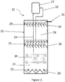
figure 2 is a schematic lateral view of a waste water purification tower according to the invention; -
figure 3 is a perspective cut view of the first set of three phase separating means of the tower offigure 2 ; -
figure 4 is a perspective cut view of the connection means between the gas hoods and the gas collecting box of the invention; -
figure 5 is a perspective view of a preferred configuration of the bottom of a reactor according to the invention; -
figure 6 illustrates a particular embodiment of internal recirculation according to the invention, and -
figure 7 is a perspective view of another configuration of the bottom of a reactor according to the invention. - Referring to
figure 2 , a high rate anaerobic wastewater purification tower 21 comprises asludge blanket reactor 22 in which are arranged from bottom to top in the following order a wastewater inlet zone 23, a mostactive zone 24 comprisingsludge 39, a first set of three phase separating means 25 comprising here two layer of adjacentparallel gas hoods 26 connected to agas collector tank 27 positioned above thereactor 22 through ariser 32, a polishingzone 28, a second set of three phase separating means 29 comprising one layer ofgas hoods 30 connected to thegas collector tank 27 through theriser 32, and a cleanwater effluent outlet 31, which can comprise a weir (not represented). Adowner 33 is connecting the bottom of thegas collector tank 27 to theactive area 24. The bottom 20 of thereactor 22 has here an accordion shape. - The
inlet zone 23 may comprise any form of waste water inlet known in the art of UASB-reactor, or specific type of water loops as will be described below. - The
gas hoods 26 of the first set of three phase separating means ofsettlers 25 are here represented identical to thegas hoods 30 of the second set ofsettlers 29. However, thefirst set 25 comprise here two layers of gas hoods for only one layer in thesecond set 29. It would also be possible to have more layers. - The
gas hoods settlers 25 is detailed infigure 3 . Thetower 21 is here a cylindrical tower. The set of settlers is arranged in a portion of the cylinder. Thegas hoods 26 are here arranged parallel) on both sides of a central compartment or collectingbox 34 dividing the cylinder portion along its diameter. The gas hoods are perpendicular to thecompartment 34 and horizontally placed towards the compartment to favor flow of the gas towards the central compartment. - Each gas hood is a kind of long up-side-down gutter arranged horizontally and having one of its ends connected to the
gas collecting box 34. Thegas collecting box 34 is arranged with ahole 35 at the middle of its top face to let thedowner 33 through and anotherhole 36 also on its top face to connect theriser 32. Eachgas hood 26 consists of anoblique pane 37, which is curved or hooked downwardly at the top 38. Thepanes 37 ofadjacent gas hoods 26 are parallel, the top 38 of one pane vertically overlapping the bottom of the adjacent gas hood, if any, thereby forming a hood. Two layers of gas hoods are here represented with thepanes 37 of each layer tilted in opposite direction. The opposite directional gas hoods are preferred for optimal efficiency. - The
parallel panes 37, show similarities with the well-known lamellas (settlers) generally used to promote sedimentation, owing to their large surface. Thesepanes 37 can therefore play here the same function, though they may be of smaller size and/or surface than usual lamellas. The height can indeed be limited, in order to reduce the global height of the first set ofsettlers 25. The hooked top 38 forming a hood to collect biogas, the term hooded lamellas can be used to describe these particular gas hoods. - Now that the various elements of the tower have been described, the waste water treatment in itself will be explained.
- The
reactor 22 is full of water at all times. It does not contain any oxygen, the treatment being strictly anaerobic. A balance of incoming and outgoing water is ensured to avoid overpressure in the reactor. - The waste water enters the
reactor 22 towards its bottom 34 with a determined flow, adjusted to promote turbulence in theactive zone 24, where sludge is present. Sludge refers to particles of microorganisms able to digest the soluble organic pollutants of the water into mainly methane and water. Typically the tower reactor is filled with well settling granular anaerobic sludge from other reactors to shorten the start-up and adaptation phase. - The digestion of the pollutant generates methane as gas bubbles, which move upwards towards the first layer of
hooded lamellas 26 of the first set ofsettlers 25, along with some sludge. The gas bubbles move up between the lamellas and are trapped under thehoods 38. As the bubbles move up, they possibly come in contact with thelamellas 37 which favor separation of the bubble and the sludge which remain on thepanes 37 and then move downwards back into the active zone, due to gravity. - The gas entrapped under the
hoods 38 flows into thegas collecting compartment 34, creating a gas lift effect that takes along sludge from under the collecting compartment with a sufficient flow into theriser 32 to promote the rise of the mixed liquor (sludge and water) and gas up to thegas collector tank 27, which is equipped with a gas outlet, generally placed on the top (not represented). The mixed liquor having risen along with the gas is decanted and re-circulated into theactive zone 24 through thedowner 33, under the force of gravity in thetank 27 and creating an important extra mixing effect which will be further discussed below - The second layer of hooded lamellas allows the remaining gas, not extracted through the first layer, to be similarly entrapped and the remaining sludge to be further separated and re-circulated downwards. Two layers of hooded lamellas are here illustrated. There could however be a larger number of layers, depending on the size and/or design of the tower. Compared to the prior art, the increased efficiency makes it possible to have a reduced number of layers of gas hoods and therefore increase the volume of the
active zone 24 and/or decrease the total volume of thereactor tank 22. - Having the layers of hooded lamellas oriented in opposite directions forces the gas bubbles into a zigzag path thereby maximizing the collection of gas under the hoods.
- Another advantage of the hooded lamellas of the invention is to avoid the upward suction effect present in conventional gas hoods. Indeed, in conventional gas hoods, the area through which the water may flow upwards is limited to the interstice between the vertical panes of two gas hoods. This creates a large acceleration of the flow in these interstices which results in dragging upwards a lot of solid materials. Due to the combined effect of a smaller gas collecting area (small cross sectional area 34), and the structure of the hooded lamellas (which also occupy a limited surface area) a lower flow acceleration is induced which again improves the separation efficiency. The combination of the efficient separating capacity of the
lamella part 37 and of the smaller cross sectional area of thehoods 38 results in a lower amount of gas and sludge being transferred to the polishing zone - The turbulence in the polishing zone is much lower than in the active zone, due to the fact that less gas is generated because:
- a small amount of sludge can pass through the first set of
settlers 25, - most of the pollutants have already been degraded in the active zone, which results in
- a lower production of biogas thereby limiting the upward flow.
- The liquid flow in the polishing zone is also lower as part of the liquid circulates trough the riser and downer, thereby short-circuiting the polishing zone.
- As a consequence, a lower amount of biogas and sludge reach the second set of
settlers 29. The need for three phase separation is therefore limited and an efficient separation can be achieved by a lower amount of layers of hooded lamellas. Typically, there are fewer layers of gas hoods in the second set of three-phase separating means than in the first set of three phase separating means. - Because the
second set 29 of three-phase separating means need to handle lower flows and lower particulate matter than thefirst set 25, the layer ofhooded lamellas 30 of thesecond set 29 may be of a different design than thehooded lamellas 26 of thefirst set 25. In particular, to ensure that there is no turbulence above the last layer of gas hoods, the upper layer of hooded lamellas is sealed to the side wall ofreactor 22, while clean water (virtually without sludge and biogas) reaches theoutlet 31 with a laminar flow. By sealed, it is meant that the layer of hooded lamellas is arranged such that no biogas gas can reach the top of thereactor 22 without passing between two lamellas and under a hood. - To further enhance the solid-liquid separation, the connection between the gas hoods and the
gas collecting box 34 can be arranged with means to retain a layer of gas in the hood. - In usual settlers, the extremity of the gas hood is connected to the gas collecting box through a simple hole crossing the vertical section of the gas collecting box. This allows all the biogas produced to be extracted to the risers via the gas collecting box. It is common knowledge that maintaining a "buffer" layer of gas under the hood enables a much better separation of the sludge and water in this zone.
- To this end, referring to
figure 4 , acover plate 40 can be placed facing thehole 41, inside thegas collecting box 34, in order to force the gas flow, illustrated by the dotted arrows, to go down to the lower part of the cover level before being able to move up again in thegas collector box 34. - This way, the highest layer of gas under the
hood 38 cannot be displaced towards thecollector box 34, as it is retained by thecover plate 40. - One
gas collecting box 34 is usually used by a set of three phase separators or settlers. However, depending on the size of the installation, a larger number of gas collecting boxes could be used, or a gas collecting box could be split in several compartments. For example, each layer of hooded lamella can be connected to a different compartment. Each box or each compartment can be equipped with its own riser. - The risers are directly connected to the gas collector tank. In large installations, there may be several independent gas collector tanks.
- The riser pipes are designed in a way to optimize the ratio between biogas and water as well as the bubble size in the riser (s) .
- A riser can have its lower end slightly inside the gas collecting box in order to allow the right flow pattern of water and biogas in the riser.
- The layers of gas hoods can be manufactured so as to be modular, i.e. easy to superimpose or remove from the set of settlers.
- The set of separating means of the invention thus enable a better separation and recirculation of the sludge into the active zone. To ensure that the sludge does not settle at the bottom of the reactor, the hooded lamellas of the invention are advantageously combined with an accordion shaped bottom of the reactor.
- Referring to
figure 5 , thebottom surface 50 of asludge reactor 52 is arranged with a accordion shaped floor or ground, i.e. with folds forming alternatingcrests 54 andvales water inlets tubes 53 extend horizontally above thevales tubes 53 here pass through thereactor wall 52 in such a way that areturn loop 56 is located outside thereactor 52, as well as the splits of one commonwaste water arrival 57 into theseveral tubes 53. - The waste water inlet pipes, though here disclosed extending along and above the vales, can be placed according to any other suitable pattern, for example in a perpendicular and/or parallel disposition regarding the bottom crests 54, they can be above or even embedded within the crests. If the pipes are placed parallel to the vales, the pipes may cross completely the
reactor tank 52 and the feeding loop is outside of the reactor tank. - If the wastewater feeding lines are placed perpendicularly to the vales and crests, as disclosed for the
reactor 72 illustrated onfigure 7 , the feedingpipes 73 can be located slightly above thevales 75 and crests 74. - Preferably, there is no fluid below the accordion floor (apart from fluid that may be flowing in pipelines running below this floor). The section below the floor may conveniently accommodate pipelines, circuitry or any other element of interest.
- The
inlet tubes 53 present orifices spread over the length of the tubes and oriented in several radial directions to create a complete mixing of waste water and sludge. - Whenever sludge fall or accumulates towards the bottom of the
reactor 52, it can be re-suspended or fluidized owing to the flow and turbulence created in this zone by the incoming waste water and further enforced by the down comer flow. - The orientation of the orifices in the
water inlet tubes 53 is adjusted to the specific reactor. For example, orifices can be positioned to create a downward flow to re-suspend sludge accumulating at the bottom of thevales - Such arrangement of waste water inlet tubes is not possible with the conical shaped reactor bottom of the prior art.
-
Figure 5 illustrates a reactor bottom with three crests and four vales. These numbers can vary depending on the size of the installation. Preferably, the inlet tubes extend along more or less the full lengths of the vales. The inlets tubes can be positioned slightly above the level of the crests, or at the same level or slightly below. - Advantageously, the vales are equipped with means to remove settled heavy unreactive solid materials, like heavy sludge, or other inorganic materials. Several extraction/removal points 59 can be arranged along a vale and connected to
sludge outlets 58, advantageously placed inside or under the accordion structure. These removal means can be manual or automated, and can depend on quality measurements made on sludge samples. - To further optimize the mixing in the active area, the downer(s) can be arranged to recirculate water from the gas collector tank with a specific flow orientation.
- Referring to
figure 6 , thedowner 60 connects the gas collecting tank to theactive zone 62, where the main anaerobic sludge degradation of pollutants occurs. At its lowest extremity, thedowner 60 is divided in twotubes tubes inlet tubes 63 at the bottom 64 of the reactor, in order to optimize the mixing in theactive zone 62. The height of the extremity of thedowners active zone 62. - This internal recirculation from the gas collector tank is a smart way to remove biogas and to improve the mixing in the lowest section of the active zone,. This means that a bigger biogas production will mean a bigger internal flow of water and gas through the riser pipes, resulting in a bigger flow through the downer pipe, improving the mixing and the biogas production as well. As mixing in the active zone is the key factor to efficiency of the anaerobic treatment installation, internal recirculation is a simple and cost effective solution.
- The gas collector and separation tank is a key element for internal recirculation where an equilibrium of pressures need to be maintained between the incoming gas/water mixture from the riser (s), the outlet of gas and the recirculation of water through the downer. Depending on the size of the treatment tower, several gas tanks may be installed, instead of one, as represented in
figure 2 . The gas tank collector may be placed inside or outside of the reactor tank/tower. The effluent clean water is collected in overflow weirs(cffig 2 , 31). - Additionally, to adjust the incoming flows in the reactor, in particular in the active zone, some of the cleaned water can also be recirculated if needed. Recirculation means of cleaned water can be installed inside the reactor or can be external.
- Overall, with a high COD load, the biogas production increases, resulting in an increase of internal recirculation, optimizing the turbulence in the sludge bed, obtaining a slight diluting effect of the inlet flow and thereby an increase of the capacity of the mass transfer phenomena.
- A cylindrical tower has been represented here. However, it is possible to have other shapes, like for example a square or rectangular section, or a deformed circular section.
- Laboratory research has confirmed that there are three main factors for an optimally functioning reactor:
- an efficient mixing between the bio-sludge and the wastewater,
- a good three-phase separation process allowing to keep the bio-sludge inside of the tower, and
- an accordion shaped waste water inlet zone.
Claims (10)
- Anaerobic waste water purification tower (21) comprising a sludge reactor (22) with, from bottom to top:- a waste water inlet zone (23),- an active zone (24),- a first set (25) of three phase separating means for separating sludge, gas and water, comprising at least two layers of adjacent gas hoods (26) connected to a gas collector tank (27) positioned above the reactor (22), and- a clean water effluent outlet (31),wherein the gas hoods (26) are hooded lamellas for improving the separation of gas, sludge and water characterized in that the layers of hooded lamellas are oriented in opposite directions.
- The waste water purification tower according to claim 1, wherein the gas hoods (26) and the gas collector tank (27) are connected by a riser (32), a downer (33) being provided for recycling water from the gas collector tank (27) to the active zone (24).
- The waste water purification tower according to one of claims 1 and 2, wherein means are provided between each gas hood (26, 30) and the gas collector tank (27) for maintaining a gas buffer in said each gas hood (26).
- The waste water purification tower according to one of claims 1 to 3, further comprising above the first set of three phase separating means:- a polishing zone (28),- a second set (29) of three phase separating means comprising at least one layer of gas hoods (30) connected at one end to a gas collector tank (27) positioned above the reactor.
- The waste water purification tower according to claim 4, wherein there are fewer layers of gas hoods in the second set (29) than in the first set (25) of three phase separating means.
- The waste water purification tower according to one of claims 4 and 5, wherein the second set (29) of three phase separating means has an upper layer of hooded lamellas (30) which is sealed to the side wall of the reactor (22).
- The waste water purification tower according to one of claims 1 to 6, wherein the bottom (34; 50) of the reactor (22; 52) is accordion shaped.
- The waste water purification tower according to claim 7, wherein the bottom of the reactor (52) is arranged with folds forming alternating crests (54) and vales (55), and perforated waste water inlets means (53) extending above and along the vales (55) to enhance resuspension of granular sludge
- The waste water purification tower according to claim 8, wherein the vales (55) are equipped with means to remove settled solid materials from the reactor (52).
- The waste water purification tower according to claim 2, wherein the lowest extremity of the downer (60) is arranged to impart a determined direction to the flow of down-coming water from the gas collector tank (27) to enhance the resuspension of granular sludge.
Priority Applications (6)
| Application Number | Priority Date | Filing Date | Title |
|---|---|---|---|
| MA52663A MA52663B1 (en) | 2019-01-30 | 2019-01-30 | Anaerobic Wastewater Purification Tower |
| EP19154556.5A EP3689829B1 (en) | 2019-01-30 | 2019-01-30 | Anaerobic waste water purification tower |
| ES19154556T ES2925463T3 (en) | 2019-01-30 | 2019-01-30 | Anaerobic wastewater treatment tower |
| PCT/EP2020/052145 WO2020157119A1 (en) | 2019-01-30 | 2020-01-29 | Anaerobic waste water purification tower |
| CN202080011522.5A CN113454034A (en) | 2019-01-30 | 2020-01-29 | Anaerobic waste water purifying tower |
| US17/426,550 US20230295025A1 (en) | 2019-01-30 | 2020-01-29 | Anaerobic waste water purification tower |
Applications Claiming Priority (1)
| Application Number | Priority Date | Filing Date | Title |
|---|---|---|---|
| EP19154556.5A EP3689829B1 (en) | 2019-01-30 | 2019-01-30 | Anaerobic waste water purification tower |
Publications (2)
| Publication Number | Publication Date |
|---|---|
| EP3689829A1 EP3689829A1 (en) | 2020-08-05 |
| EP3689829B1 true EP3689829B1 (en) | 2022-06-01 |
Family
ID=65268840
Family Applications (1)
| Application Number | Title | Priority Date | Filing Date |
|---|---|---|---|
| EP19154556.5A Active EP3689829B1 (en) | 2019-01-30 | 2019-01-30 | Anaerobic waste water purification tower |
Country Status (3)
| Country | Link |
|---|---|
| EP (1) | EP3689829B1 (en) |
| ES (1) | ES2925463T3 (en) |
| MA (1) | MA52663B1 (en) |
Family Cites Families (5)
| Publication number | Priority date | Publication date | Assignee | Title |
|---|---|---|---|---|
| DE4042223A1 (en) * | 1990-12-29 | 1992-07-02 | Pwa Industriepapier Gmbh | REACTOR AND METHOD FOR CONTINUOUS MECHANICAL AND ANAEROBIC BIOLOGICAL CLEANING OF SOLID WASTE WATER |
| DE59609368D1 (en) * | 1996-05-22 | 2002-07-25 | Va Tech Wabag Schweiz Ag Winte | Process and reactor for anaerobic wastewater treatment in a sludge bed |
| AU2005332712B2 (en) * | 2005-06-10 | 2011-08-11 | Paques I.P. B.V. | Anaerobic purification device |
| CN202297249U (en) * | 2011-10-12 | 2012-07-04 | 林长青 | Inner-circulated anaerobic fluidize bed reactor |
| CN107986440A (en) * | 2017-12-04 | 2018-05-04 | 魏发宝 | The UASB efficient anaerobic tanks of industrial waste water centralized treatment system |
-
2019
- 2019-01-30 MA MA52663A patent/MA52663B1/en unknown
- 2019-01-30 EP EP19154556.5A patent/EP3689829B1/en active Active
- 2019-01-30 ES ES19154556T patent/ES2925463T3/en active Active
Also Published As
| Publication number | Publication date |
|---|---|
| ES2925463T3 (en) | 2022-10-18 |
| MA52663B1 (en) | 2022-09-30 |
| EP3689829A1 (en) | 2020-08-05 |
| MA52663A (en) | 2020-08-05 |
Similar Documents
| Publication | Publication Date | Title |
|---|---|---|
| US20230295025A1 (en) | Anaerobic waste water purification tower | |
| EP2346788B1 (en) | Settling device, purifier comprising a settling device and methods for anaerobic or aerobic purification of waste water | |
| US8043506B2 (en) | Process and reactor for anaerobic waste water purification | |
| US8021552B2 (en) | Process and reactor for anaerobic waste water purification | |
| US8133392B2 (en) | Three-phase cascade separator | |
| EP0354744A2 (en) | Clarification apparatus | |
| CN102471109B (en) | Reactor for anaerobically purifying waste water comprising multi-phase separator devices | |
| AU2011318244B2 (en) | An effluent treatment unit | |
| EP3689829B1 (en) | Anaerobic waste water purification tower | |
| CN1303011C (en) | Reactor with two gas separators and method for the anaerobic treatment of liquids | |
| WO2023123992A1 (en) | High-efficiency skid-mounted three-phase separator in high-load anaerobic system | |
| KR100781400B1 (en) | Precipitating method in settling pond of sewage disposal plant and settling pond for precipitating | |
| BE1027000A9 (en) | Anaerobic wastewater treatment reactor | |
| KR100491353B1 (en) | liquid-solid seperator | |
| BR112021015104B1 (en) | ANAEROBIC WASTEWATER PURIFICATION TOWER | |
| BR112021015104A2 (en) | ANAEROBIC WASTE WATER PURIFICATION TOWER | |
| CN101613153A (en) | A kind of vertical anaerobic process tank integrated triphase separator | |
| CN2729055Y (en) | Vertical tilted plate separator | |
| CN203007036U (en) | Elliptic low-speed anaerobic reactor | |
| JP2011092943A5 (en) | ||
| CN206014505U (en) | A kind of collection chamber of anaerobic reactor | |
| JP2000051888A (en) | Water treatment apparatus and method | |
| CN115636504A (en) | Integrated single-layer sloping plate three-phase separator for anaerobic treatment | |
| CN101422662B (en) | Solid liquid gas three-phase separation device | |
| CN103011403A (en) | Elliptical low-speed anaerobic reactor |
Legal Events
| Date | Code | Title | Description |
|---|---|---|---|
| PUAI | Public reference made under article 153(3) epc to a published international application that has entered the european phase |
Free format text: ORIGINAL CODE: 0009012 |
|
| STAA | Information on the status of an ep patent application or granted ep patent |
Free format text: STATUS: THE APPLICATION HAS BEEN PUBLISHED |
|
| AK | Designated contracting states |
Kind code of ref document: A1 Designated state(s): AL AT BE BG CH CY CZ DE DK EE ES FI FR GB GR HR HU IE IS IT LI LT LU LV MC MK MT NL NO PL PT RO RS SE SI SK SM TR |
|
| AX | Request for extension of the european patent |
Extension state: BA ME |
|
| STAA | Information on the status of an ep patent application or granted ep patent |
Free format text: STATUS: REQUEST FOR EXAMINATION WAS MADE |
|
| 17P | Request for examination filed |
Effective date: 20210112 |
|
| RAV | Requested validation state of the european patent: fee paid |
Extension state: MA Effective date: 20210112 |
|
| RBV | Designated contracting states (corrected) |
Designated state(s): AL AT BE BG CH CY CZ DE DK EE ES FI FR GB GR HR HU IE IS IT LI LT LU LV MC MK MT NL NO PL PT RO RS SE SI SK SM TR |
|
| STAA | Information on the status of an ep patent application or granted ep patent |
Free format text: STATUS: EXAMINATION IS IN PROGRESS |
|
| 17Q | First examination report despatched |
Effective date: 20210520 |
|
| GRAP | Despatch of communication of intention to grant a patent |
Free format text: ORIGINAL CODE: EPIDOSNIGR1 |
|
| STAA | Information on the status of an ep patent application or granted ep patent |
Free format text: STATUS: GRANT OF PATENT IS INTENDED |
|
| INTG | Intention to grant announced |
Effective date: 20211221 |
|
| GRAS | Grant fee paid |
Free format text: ORIGINAL CODE: EPIDOSNIGR3 |
|
| GRAA | (expected) grant |
Free format text: ORIGINAL CODE: 0009210 |
|
| STAA | Information on the status of an ep patent application or granted ep patent |
Free format text: STATUS: THE PATENT HAS BEEN GRANTED |
|
| AK | Designated contracting states |
Kind code of ref document: B1 Designated state(s): AL AT BE BG CH CY CZ DE DK EE ES FI FR GB GR HR HU IE IS IT LI LT LU LV MC MK MT NL NO PL PT RO RS SE SI SK SM TR |
|
| REG | Reference to a national code |
Ref country code: GB Ref legal event code: FG4D |
|
| REG | Reference to a national code |
Ref country code: AT Ref legal event code: REF Ref document number: 1495295 Country of ref document: AT Kind code of ref document: T Effective date: 20220615 Ref country code: CH Ref legal event code: EP Ref country code: DE Ref legal event code: R096 Ref document number: 602019015295 Country of ref document: DE |
|
| REG | Reference to a national code |
Ref country code: IE Ref legal event code: FG4D |
|
| REG | Reference to a national code |
Ref country code: NL Ref legal event code: FP |
|
| REG | Reference to a national code |
Ref country code: LT Ref legal event code: MG9D |
|
| REG | Reference to a national code |
Ref country code: MA Ref legal event code: VAGR Ref document number: 52663 Country of ref document: MA Kind code of ref document: B1 |
|
| REG | Reference to a national code |
Ref country code: ES Ref legal event code: FG2A Ref document number: 2925463 Country of ref document: ES Kind code of ref document: T3 Effective date: 20221018 |
|
| PG25 | Lapsed in a contracting state [announced via postgrant information from national office to epo] |
Ref country code: SE Free format text: LAPSE BECAUSE OF FAILURE TO SUBMIT A TRANSLATION OF THE DESCRIPTION OR TO PAY THE FEE WITHIN THE PRESCRIBED TIME-LIMIT Effective date: 20220601 Ref country code: NO Free format text: LAPSE BECAUSE OF FAILURE TO SUBMIT A TRANSLATION OF THE DESCRIPTION OR TO PAY THE FEE WITHIN THE PRESCRIBED TIME-LIMIT Effective date: 20220901 Ref country code: LT Free format text: LAPSE BECAUSE OF FAILURE TO SUBMIT A TRANSLATION OF THE DESCRIPTION OR TO PAY THE FEE WITHIN THE PRESCRIBED TIME-LIMIT Effective date: 20220601 Ref country code: HR Free format text: LAPSE BECAUSE OF FAILURE TO SUBMIT A TRANSLATION OF THE DESCRIPTION OR TO PAY THE FEE WITHIN THE PRESCRIBED TIME-LIMIT Effective date: 20220601 Ref country code: FI Free format text: LAPSE BECAUSE OF FAILURE TO SUBMIT A TRANSLATION OF THE DESCRIPTION OR TO PAY THE FEE WITHIN THE PRESCRIBED TIME-LIMIT Effective date: 20220601 Ref country code: BG Free format text: LAPSE BECAUSE OF FAILURE TO SUBMIT A TRANSLATION OF THE DESCRIPTION OR TO PAY THE FEE WITHIN THE PRESCRIBED TIME-LIMIT Effective date: 20220901 |
|
| REG | Reference to a national code |
Ref country code: AT Ref legal event code: MK05 Ref document number: 1495295 Country of ref document: AT Kind code of ref document: T Effective date: 20220601 |
|
| PG25 | Lapsed in a contracting state [announced via postgrant information from national office to epo] |
Ref country code: RS Free format text: LAPSE BECAUSE OF FAILURE TO SUBMIT A TRANSLATION OF THE DESCRIPTION OR TO PAY THE FEE WITHIN THE PRESCRIBED TIME-LIMIT Effective date: 20220601 Ref country code: PL Free format text: LAPSE BECAUSE OF FAILURE TO SUBMIT A TRANSLATION OF THE DESCRIPTION OR TO PAY THE FEE WITHIN THE PRESCRIBED TIME-LIMIT Effective date: 20220601 Ref country code: LV Free format text: LAPSE BECAUSE OF FAILURE TO SUBMIT A TRANSLATION OF THE DESCRIPTION OR TO PAY THE FEE WITHIN THE PRESCRIBED TIME-LIMIT Effective date: 20220601 |
|
| PG25 | Lapsed in a contracting state [announced via postgrant information from national office to epo] |
Ref country code: SM Free format text: LAPSE BECAUSE OF FAILURE TO SUBMIT A TRANSLATION OF THE DESCRIPTION OR TO PAY THE FEE WITHIN THE PRESCRIBED TIME-LIMIT Effective date: 20220601 Ref country code: SK Free format text: LAPSE BECAUSE OF FAILURE TO SUBMIT A TRANSLATION OF THE DESCRIPTION OR TO PAY THE FEE WITHIN THE PRESCRIBED TIME-LIMIT Effective date: 20220601 Ref country code: RO Free format text: LAPSE BECAUSE OF FAILURE TO SUBMIT A TRANSLATION OF THE DESCRIPTION OR TO PAY THE FEE WITHIN THE PRESCRIBED TIME-LIMIT Effective date: 20220601 Ref country code: PT Free format text: LAPSE BECAUSE OF FAILURE TO SUBMIT A TRANSLATION OF THE DESCRIPTION OR TO PAY THE FEE WITHIN THE PRESCRIBED TIME-LIMIT Effective date: 20221003 Ref country code: EE Free format text: LAPSE BECAUSE OF FAILURE TO SUBMIT A TRANSLATION OF THE DESCRIPTION OR TO PAY THE FEE WITHIN THE PRESCRIBED TIME-LIMIT Effective date: 20220601 Ref country code: CZ Free format text: LAPSE BECAUSE OF FAILURE TO SUBMIT A TRANSLATION OF THE DESCRIPTION OR TO PAY THE FEE WITHIN THE PRESCRIBED TIME-LIMIT Effective date: 20220601 Ref country code: AT Free format text: LAPSE BECAUSE OF FAILURE TO SUBMIT A TRANSLATION OF THE DESCRIPTION OR TO PAY THE FEE WITHIN THE PRESCRIBED TIME-LIMIT Effective date: 20220601 |
|
| PG25 | Lapsed in a contracting state [announced via postgrant information from national office to epo] |
Ref country code: IS Free format text: LAPSE BECAUSE OF FAILURE TO SUBMIT A TRANSLATION OF THE DESCRIPTION OR TO PAY THE FEE WITHIN THE PRESCRIBED TIME-LIMIT Effective date: 20221001 |
|
| REG | Reference to a national code |
Ref country code: DE Ref legal event code: R097 Ref document number: 602019015295 Country of ref document: DE |
|
| PG25 | Lapsed in a contracting state [announced via postgrant information from national office to epo] |
Ref country code: AL Free format text: LAPSE BECAUSE OF FAILURE TO SUBMIT A TRANSLATION OF THE DESCRIPTION OR TO PAY THE FEE WITHIN THE PRESCRIBED TIME-LIMIT Effective date: 20220601 |
|
| PLBE | No opposition filed within time limit |
Free format text: ORIGINAL CODE: 0009261 |
|
| STAA | Information on the status of an ep patent application or granted ep patent |
Free format text: STATUS: NO OPPOSITION FILED WITHIN TIME LIMIT |
|
| PG25 | Lapsed in a contracting state [announced via postgrant information from national office to epo] |
Ref country code: DK Free format text: LAPSE BECAUSE OF FAILURE TO SUBMIT A TRANSLATION OF THE DESCRIPTION OR TO PAY THE FEE WITHIN THE PRESCRIBED TIME-LIMIT Effective date: 20220601 |
|
| PGFP | Annual fee paid to national office [announced via postgrant information from national office to epo] |
Ref country code: FR Payment date: 20230123 Year of fee payment: 5 Ref country code: ES Payment date: 20230208 Year of fee payment: 5 |
|
| 26N | No opposition filed |
Effective date: 20230302 |
|
| PG25 | Lapsed in a contracting state [announced via postgrant information from national office to epo] |
Ref country code: SI Free format text: LAPSE BECAUSE OF FAILURE TO SUBMIT A TRANSLATION OF THE DESCRIPTION OR TO PAY THE FEE WITHIN THE PRESCRIBED TIME-LIMIT Effective date: 20220601 |
|
| PGFP | Annual fee paid to national office [announced via postgrant information from national office to epo] |
Ref country code: IT Payment date: 20230109 Year of fee payment: 5 Ref country code: GB Payment date: 20230110 Year of fee payment: 5 Ref country code: DE Payment date: 20230106 Year of fee payment: 5 Ref country code: BE Payment date: 20230123 Year of fee payment: 5 |
|
| P01 | Opt-out of the competence of the unified patent court (upc) registered |
Effective date: 20230503 |
|
| PGFP | Annual fee paid to national office [announced via postgrant information from national office to epo] |
Ref country code: NL Payment date: 20230125 Year of fee payment: 5 |
|
| REG | Reference to a national code |
Ref country code: CH Ref legal event code: PL |
|
| PG25 | Lapsed in a contracting state [announced via postgrant information from national office to epo] |
Ref country code: LU Free format text: LAPSE BECAUSE OF NON-PAYMENT OF DUE FEES Effective date: 20230130 |
|
| PG25 | Lapsed in a contracting state [announced via postgrant information from national office to epo] |
Ref country code: LI Free format text: LAPSE BECAUSE OF NON-PAYMENT OF DUE FEES Effective date: 20230131 Ref country code: CH Free format text: LAPSE BECAUSE OF NON-PAYMENT OF DUE FEES Effective date: 20230131 |
|
| PG25 | Lapsed in a contracting state [announced via postgrant information from national office to epo] |
Ref country code: IE Free format text: LAPSE BECAUSE OF NON-PAYMENT OF DUE FEES Effective date: 20230130 |
|
| PGFP | Annual fee paid to national office [announced via postgrant information from national office to epo] |
Ref country code: NL Payment date: 20240126 Year of fee payment: 6 |