EP3689708A1 - Method and device for delivering steering intention of autonomous driving module or driver to steering apparatus of subject vehicle more accurately - Google Patents
Method and device for delivering steering intention of autonomous driving module or driver to steering apparatus of subject vehicle more accurately Download PDFInfo
- Publication number
- EP3689708A1 EP3689708A1 EP20153038.3A EP20153038A EP3689708A1 EP 3689708 A1 EP3689708 A1 EP 3689708A1 EP 20153038 A EP20153038 A EP 20153038A EP 3689708 A1 EP3689708 A1 EP 3689708A1
- Authority
- EP
- European Patent Office
- Prior art keywords
- steering
- angles
- subject
- past
- guide values
- Prior art date
- Legal status (The legal status is an assumption and is not a legal conclusion. Google has not performed a legal analysis and makes no representation as to the accuracy of the status listed.)
- Granted
Links
- 238000000034 method Methods 0.000 title claims abstract description 61
- 239000013598 vector Substances 0.000 claims description 41
- 230000008569 process Effects 0.000 claims description 30
- 230000006870 function Effects 0.000 claims description 10
- 238000001514 detection method Methods 0.000 claims description 7
- 238000005516 engineering process Methods 0.000 description 5
- 230000015556 catabolic process Effects 0.000 description 4
- 238000004891 communication Methods 0.000 description 3
- 238000009826 distribution Methods 0.000 description 3
- 241001465754 Metazoa Species 0.000 description 2
- 230000008901 benefit Effects 0.000 description 2
- 238000010586 diagram Methods 0.000 description 2
- 230000000694 effects Effects 0.000 description 2
- 230000009471 action Effects 0.000 description 1
- 238000007792 addition Methods 0.000 description 1
- 238000004364 calculation method Methods 0.000 description 1
- 238000004590 computer program Methods 0.000 description 1
- 238000010801 machine learning Methods 0.000 description 1
- 230000007257 malfunction Effects 0.000 description 1
- 230000004048 modification Effects 0.000 description 1
- 238000012986 modification Methods 0.000 description 1
- 230000003287 optical effect Effects 0.000 description 1
Images


Classifications
-
- B—PERFORMING OPERATIONS; TRANSPORTING
- B62—LAND VEHICLES FOR TRAVELLING OTHERWISE THAN ON RAILS
- B62D—MOTOR VEHICLES; TRAILERS
- B62D15/00—Steering not otherwise provided for
- B62D15/02—Steering position indicators ; Steering position determination; Steering aids
- B62D15/021—Determination of steering angle
-
- B—PERFORMING OPERATIONS; TRANSPORTING
- B62—LAND VEHICLES FOR TRAVELLING OTHERWISE THAN ON RAILS
- B62D—MOTOR VEHICLES; TRAILERS
- B62D5/00—Power-assisted or power-driven steering
- B62D5/04—Power-assisted or power-driven steering electrical, e.g. using an electric servo-motor connected to, or forming part of, the steering gear
- B62D5/0457—Power-assisted or power-driven steering electrical, e.g. using an electric servo-motor connected to, or forming part of, the steering gear characterised by control features of the drive means as such
- B62D5/0481—Power-assisted or power-driven steering electrical, e.g. using an electric servo-motor connected to, or forming part of, the steering gear characterised by control features of the drive means as such monitoring the steering system, e.g. failures
-
- B—PERFORMING OPERATIONS; TRANSPORTING
- B62—LAND VEHICLES FOR TRAVELLING OTHERWISE THAN ON RAILS
- B62D—MOTOR VEHICLES; TRAILERS
- B62D15/00—Steering not otherwise provided for
- B62D15/02—Steering position indicators ; Steering position determination; Steering aids
- B62D15/025—Active steering aids, e.g. helping the driver by actively influencing the steering system after environment evaluation
-
- B—PERFORMING OPERATIONS; TRANSPORTING
- B60—VEHICLES IN GENERAL
- B60W—CONJOINT CONTROL OF VEHICLE SUB-UNITS OF DIFFERENT TYPE OR DIFFERENT FUNCTION; CONTROL SYSTEMS SPECIALLY ADAPTED FOR HYBRID VEHICLES; ROAD VEHICLE DRIVE CONTROL SYSTEMS FOR PURPOSES NOT RELATED TO THE CONTROL OF A PARTICULAR SUB-UNIT
- B60W10/00—Conjoint control of vehicle sub-units of different type or different function
- B60W10/20—Conjoint control of vehicle sub-units of different type or different function including control of steering systems
-
- B—PERFORMING OPERATIONS; TRANSPORTING
- B60—VEHICLES IN GENERAL
- B60W—CONJOINT CONTROL OF VEHICLE SUB-UNITS OF DIFFERENT TYPE OR DIFFERENT FUNCTION; CONTROL SYSTEMS SPECIALLY ADAPTED FOR HYBRID VEHICLES; ROAD VEHICLE DRIVE CONTROL SYSTEMS FOR PURPOSES NOT RELATED TO THE CONTROL OF A PARTICULAR SUB-UNIT
- B60W50/00—Details of control systems for road vehicle drive control not related to the control of a particular sub-unit, e.g. process diagnostic or vehicle driver interfaces
- B60W50/08—Interaction between the driver and the control system
- B60W50/082—Selecting or switching between different modes of propelling
-
- B—PERFORMING OPERATIONS; TRANSPORTING
- B60—VEHICLES IN GENERAL
- B60W—CONJOINT CONTROL OF VEHICLE SUB-UNITS OF DIFFERENT TYPE OR DIFFERENT FUNCTION; CONTROL SYSTEMS SPECIALLY ADAPTED FOR HYBRID VEHICLES; ROAD VEHICLE DRIVE CONTROL SYSTEMS FOR PURPOSES NOT RELATED TO THE CONTROL OF A PARTICULAR SUB-UNIT
- B60W50/00—Details of control systems for road vehicle drive control not related to the control of a particular sub-unit, e.g. process diagnostic or vehicle driver interfaces
- B60W50/08—Interaction between the driver and the control system
- B60W50/10—Interpretation of driver requests or demands
-
- B—PERFORMING OPERATIONS; TRANSPORTING
- B60—VEHICLES IN GENERAL
- B60W—CONJOINT CONTROL OF VEHICLE SUB-UNITS OF DIFFERENT TYPE OR DIFFERENT FUNCTION; CONTROL SYSTEMS SPECIALLY ADAPTED FOR HYBRID VEHICLES; ROAD VEHICLE DRIVE CONTROL SYSTEMS FOR PURPOSES NOT RELATED TO THE CONTROL OF A PARTICULAR SUB-UNIT
- B60W50/00—Details of control systems for road vehicle drive control not related to the control of a particular sub-unit, e.g. process diagnostic or vehicle driver interfaces
- B60W50/08—Interaction between the driver and the control system
- B60W50/14—Means for informing the driver, warning the driver or prompting a driver intervention
-
- B—PERFORMING OPERATIONS; TRANSPORTING
- B60—VEHICLES IN GENERAL
- B60W—CONJOINT CONTROL OF VEHICLE SUB-UNITS OF DIFFERENT TYPE OR DIFFERENT FUNCTION; CONTROL SYSTEMS SPECIALLY ADAPTED FOR HYBRID VEHICLES; ROAD VEHICLE DRIVE CONTROL SYSTEMS FOR PURPOSES NOT RELATED TO THE CONTROL OF A PARTICULAR SUB-UNIT
- B60W60/00—Drive control systems specially adapted for autonomous road vehicles
- B60W60/001—Planning or execution of driving tasks
-
- B—PERFORMING OPERATIONS; TRANSPORTING
- B60—VEHICLES IN GENERAL
- B60W—CONJOINT CONTROL OF VEHICLE SUB-UNITS OF DIFFERENT TYPE OR DIFFERENT FUNCTION; CONTROL SYSTEMS SPECIALLY ADAPTED FOR HYBRID VEHICLES; ROAD VEHICLE DRIVE CONTROL SYSTEMS FOR PURPOSES NOT RELATED TO THE CONTROL OF A PARTICULAR SUB-UNIT
- B60W60/00—Drive control systems specially adapted for autonomous road vehicles
- B60W60/005—Handover processes
- B60W60/0051—Handover processes from occupants to vehicle
-
- B—PERFORMING OPERATIONS; TRANSPORTING
- B60—VEHICLES IN GENERAL
- B60W—CONJOINT CONTROL OF VEHICLE SUB-UNITS OF DIFFERENT TYPE OR DIFFERENT FUNCTION; CONTROL SYSTEMS SPECIALLY ADAPTED FOR HYBRID VEHICLES; ROAD VEHICLE DRIVE CONTROL SYSTEMS FOR PURPOSES NOT RELATED TO THE CONTROL OF A PARTICULAR SUB-UNIT
- B60W60/00—Drive control systems specially adapted for autonomous road vehicles
- B60W60/005—Handover processes
- B60W60/0053—Handover processes from vehicle to occupant
-
- B—PERFORMING OPERATIONS; TRANSPORTING
- B62—LAND VEHICLES FOR TRAVELLING OTHERWISE THAN ON RAILS
- B62D—MOTOR VEHICLES; TRAILERS
- B62D15/00—Steering not otherwise provided for
- B62D15/02—Steering position indicators ; Steering position determination; Steering aids
- B62D15/027—Parking aids, e.g. instruction means
- B62D15/0285—Parking performed automatically
-
- B—PERFORMING OPERATIONS; TRANSPORTING
- B62—LAND VEHICLES FOR TRAVELLING OTHERWISE THAN ON RAILS
- B62D—MOTOR VEHICLES; TRAILERS
- B62D15/00—Steering not otherwise provided for
- B62D15/02—Steering position indicators ; Steering position determination; Steering aids
- B62D15/029—Steering assistants using warnings or proposing actions to the driver without influencing the steering system
-
- B—PERFORMING OPERATIONS; TRANSPORTING
- B62—LAND VEHICLES FOR TRAVELLING OTHERWISE THAN ON RAILS
- B62D—MOTOR VEHICLES; TRAILERS
- B62D6/00—Arrangements for automatically controlling steering depending on driving conditions sensed and responded to, e.g. control circuits
- B62D6/002—Arrangements for automatically controlling steering depending on driving conditions sensed and responded to, e.g. control circuits computing target steering angles for front or rear wheels
-
- G—PHYSICS
- G05—CONTROLLING; REGULATING
- G05D—SYSTEMS FOR CONTROLLING OR REGULATING NON-ELECTRIC VARIABLES
- G05D1/00—Control of position, course or altitude of land, water, air, or space vehicles, e.g. automatic pilot
- G05D1/0088—Control of position, course or altitude of land, water, air, or space vehicles, e.g. automatic pilot characterized by the autonomous decision making process, e.g. artificial intelligence, predefined behaviours
-
- B—PERFORMING OPERATIONS; TRANSPORTING
- B60—VEHICLES IN GENERAL
- B60W—CONJOINT CONTROL OF VEHICLE SUB-UNITS OF DIFFERENT TYPE OR DIFFERENT FUNCTION; CONTROL SYSTEMS SPECIALLY ADAPTED FOR HYBRID VEHICLES; ROAD VEHICLE DRIVE CONTROL SYSTEMS FOR PURPOSES NOT RELATED TO THE CONTROL OF A PARTICULAR SUB-UNIT
- B60W50/00—Details of control systems for road vehicle drive control not related to the control of a particular sub-unit, e.g. process diagnostic or vehicle driver interfaces
- B60W2050/0001—Details of the control system
- B60W2050/0002—Automatic control, details of type of controller or control system architecture
- B60W2050/0004—In digital systems, e.g. discrete-time systems involving sampling
- B60W2050/0005—Processor details or data handling, e.g. memory registers or chip architecture
-
- B—PERFORMING OPERATIONS; TRANSPORTING
- B60—VEHICLES IN GENERAL
- B60W—CONJOINT CONTROL OF VEHICLE SUB-UNITS OF DIFFERENT TYPE OR DIFFERENT FUNCTION; CONTROL SYSTEMS SPECIALLY ADAPTED FOR HYBRID VEHICLES; ROAD VEHICLE DRIVE CONTROL SYSTEMS FOR PURPOSES NOT RELATED TO THE CONTROL OF A PARTICULAR SUB-UNIT
- B60W50/00—Details of control systems for road vehicle drive control not related to the control of a particular sub-unit, e.g. process diagnostic or vehicle driver interfaces
- B60W2050/0001—Details of the control system
- B60W2050/0019—Control system elements or transfer functions
- B60W2050/0026—Lookup tables or parameter maps
-
- B—PERFORMING OPERATIONS; TRANSPORTING
- B60—VEHICLES IN GENERAL
- B60W—CONJOINT CONTROL OF VEHICLE SUB-UNITS OF DIFFERENT TYPE OR DIFFERENT FUNCTION; CONTROL SYSTEMS SPECIALLY ADAPTED FOR HYBRID VEHICLES; ROAD VEHICLE DRIVE CONTROL SYSTEMS FOR PURPOSES NOT RELATED TO THE CONTROL OF A PARTICULAR SUB-UNIT
- B60W2540/00—Input parameters relating to occupants
- B60W2540/18—Steering angle
-
- B—PERFORMING OPERATIONS; TRANSPORTING
- B60—VEHICLES IN GENERAL
- B60W—CONJOINT CONTROL OF VEHICLE SUB-UNITS OF DIFFERENT TYPE OR DIFFERENT FUNCTION; CONTROL SYSTEMS SPECIALLY ADAPTED FOR HYBRID VEHICLES; ROAD VEHICLE DRIVE CONTROL SYSTEMS FOR PURPOSES NOT RELATED TO THE CONTROL OF A PARTICULAR SUB-UNIT
- B60W2556/00—Input parameters relating to data
- B60W2556/10—Historical data
Definitions
- the present disclosure relates to a method and a device to be used for an autonomous vehicle; and more particularly to the method for delivering a steering intention of an autonomous driving module or a driver to a steering apparatus of a subject vehicle more accurately, and the device using the same.
- the autonomous driving technologies refer to technologies that allow an autonomous vehicle to travel safely by collecting and using external information through modules capable of acquiring the external information, such as a sensor and a camera mounted on the vehicle.
- the autonomous driving technologies have been developed so much that the autonomous vehicle is able to drive hundreds of kilometers without an accident.
- a method for delivering a steering intention of an autonomous driving module or a driver to a steering apparatus of a subject vehicle more accurately by using a reference map which is a rule-set generated by referring to past driving records of the subject vehicle including steps of: (a) a computing device, if a subject intended steering signal included in a subject control signal inputted by the autonomous driving module or the driver at a current timing is acquired, instructing a signal adjustment module to select, by referring to the reference map generated by using past adjusted steering signals and past actual steered angles included in the past driving records, one or more specific reference steering guide values, among reference steering guide values of the reference map, corresponding to the subject intended steering signal; and (b) the computing device (i) adjusting the subject intended steering signal by referring to the specific reference steering guide values, in order to generate a subject adjusted steering signal, and (ii) transmitting the subject adjusted steering signal to the steering apparatus, to thereby support the steering apparatus to rotate the subject vehicle by a specific steering
- the method before the step of (a), further includes a step of: (a0) the computing device (i) generating a first vector including information on the past adjusted steering signals, a second vector including information on the past actual steered angles, and a third vector including information on prescribed reference actual steering angles, (ii) performing a regression operation by using the first, the second, and the third vectors, and (iii) generating the reference map including information on (iii-1) the reference steering guide values generated by the regression operation, (iii-2) the reference actual steering angles and (iii-3) a relationship between the reference steering guide values and the reference actual steering angles.
- the past adjusted steering signals have been acquired by using past control signals transmitted by the autonomous driving module or the driver for a prescribed time range from a certain past timing to the current timing, and wherein the past actual steered angles are acquired by analyzing a motion of the subject vehicle performed during said time range through at least one of a computer vision module and a steering detection sensor which interwork with the computing device.
- the method further includes a step of: (a1) the computing device generating each of steering accuracy scores by referring to each of the reference actual steering angles and its corresponding reference steering guide values, and determining whether to transmit an alarm on the steering apparatus to the driver or not by referring to the steering accuracy scores.
- the computing device compares sizes of each of the reference actual steering angles and its corresponding reference steering guide values, to thereby generate each of the steering accuracy scores corresponding to each of similarities between each of the reference actual steering angles and its corresponding reference steering guide values, and transmits the alarm if a ratio of the number of specific steering accuracy scores to the total number of the steering accuracy scores is larger than a first threshold, wherein the specific steering accuracy scores, selected among the steering accuracy scores, are smaller than a second threshold.
- the computing device instructs the signal adjustment module to (i) calculate similarity scores between the reference actual steering angles and the subject intended steering signal by referring to the subject intended steering signal representing the specific steering angle, (ii) find a first to an N-th specific reference actual steering angles corresponding to specific similarity scores which are the top N ones among the similarity scores, and (iii) find a first to an N-th specific reference steering guide values corresponding to the first to the N-th specific reference actual steering angles by referring to information on relationships between the reference actual steering angles and its corresponding reference steering guide values, and wherein, at the step of (b), the computing device performs a linear interpolation by referring to the first to the N-th specific reference actual steering angles and their corresponding first to the N-th specific reference steering guide values, to thereby generate the subject adjusted steering signal.
- a computing device for delivering a steering intention of an autonomous driving module or a driver to a steering apparatus of a subject vehicle more accurately by using a reference map which is a rule-set generated by referring to past driving records of the subject vehicle, including: at least one memory that stores instructions; and at least one processor configured to execute the instructions to perform processes of: (I) if a subject intended steering signal included in a subject control signal inputted by the autonomous driving module or the driver at a current timing is acquired, instructing a signal adjustment module to select, by referring to the reference map generated by using past adjusted steering signals and past actual steered angles included in the past driving records, one or more specific reference steering guide values, among reference steering guide values of the reference map, corresponding to the subject intended steering signal; and (II) (i) adjusting the subject intended steering signal by referring to the specific reference steering guide values, in order to generate a subject adjusted steering signal, and (ii) transmitting the subject adjusted steering signal to the steering apparatus, to
- the processor before the process of (I), the processor further performs a process of: (I0) (i) generating a first vector including information on the past adjusted steering signals, a second vector including information on the past actual steered angles, and a third vector including information on prescribed reference actual steering angles, (ii) performing a regression operation by using the first, the second, and the third vectors, and (iii) generating the reference map including information on (iii-1) the reference steering guide values generated by the regression operation, (iii-2) the reference actual steering angles and (iii-3) a relationship between the reference steering guide values and the reference actual steering angles.
- the past adjusted steering signals have been acquired by using past control signals transmitted by the autonomous driving module or the driver for a prescribed time range from a certain past timing to the current timing, and wherein the past actual steered angles are acquired by analyzing a motion of the subject vehicle performed during said time range through at least one of a computer vision module and a steering detection sensor which interwork with the computing device.
- the processor further performs a process of: (I1) generating each of steering accuracy scores by referring to each of the reference actual steering angles and its corresponding reference steering guide values, and determining whether to transmit an alarm on the steering apparatus to the driver or not by referring to the steering accuracy scores.
- the processor compares sizes of each of the reference actual steering angles and its corresponding reference steering guide values, to thereby generate each of the steering accuracy scores corresponding to each of similarities between each of the reference actual steering angles and its corresponding reference steering guide values, and transmits the alarm if a ratio of the number of specific steering accuracy scores to the total number of the steering accuracy scores is larger than a first threshold, wherein sizes of the specific steering accuracy scores, selected among the steering accuracy scores, are smaller than a second threshold.
- the processor performs the processes of (I0) and (I1) if a trigger corresponding to a start of the subject vehicle is detected.
- the processor instructs the signal adjustment module to (i) calculate similarity scores between the reference actual steering angles and the subject intended steering signal by referring to the subject intended steering signal representing the specific steering angle, (ii) find a first to an N-th specific reference actual steering angles corresponding to specific similarity scores which are the top N ones among the similarity scores, and (iii) find a first to an N-th specific reference steering guide values corresponding to the first to the N-th specific reference actual steering angles by referring to information on relationships between the reference actual steering angles and its corresponding reference steering guide values, and wherein, at the process of (II), the processor performs a linear interpolation by referring to the first to the N-th specific reference actual steering angles and their corresponding first to the N-th specific reference steering guide values, to thereby generate the subject adjusted steering signal.
- recordable media that are readable by a computer for storing a computer program to execute the method of the present disclosure is further provided.
- Any images referred to in the present disclosure may include images related to any roads paved or unpaved, in which case the objects on the roads or near the roads may include vehicles, persons, animals, plants, buildings, flying objects like planes or drones, or any other obstacles which may appear in a road-related scene, but the scope of the present disclosure is not limited thereto.
- said any images referred to in the present disclosure may include images not related to any roads, such as images related to alleyway, land lots, sea, lakes, rivers, mountains, forests, deserts, sky, or any indoor space
- the objects in said any images may include vehicles, persons, animals, plants, buildings, flying objects like planes or drones, ships, amphibious planes or ships, or any other obstacles which may appear in a scene related to alleyway, land lots, sea, lakes, rivers, mountains, forests, deserts, sky, or any indoor space, but the scope of the present disclosure is not limited thereto.
- Fig. 1 is a drawing schematically illustrating a configuration of a computing device performing a method for delivering a steering intention of an autonomous driving module or a driver to a steering apparatus of a subject vehicle more accurately in accordance with one example embodiment of the present disclosure.
- the computing device 100 may include a signal adjustment module 130 to be described later. Processes of input/output and computations of the signal adjustment module 130 may be respectively performed by at least one communication part 110 and at least one processor 120. However, detailed communication schematics between the communication part 110 and the processor 120 are omitted in Fig. 1 .
- a memory 115 may have stored various instructions to be described later, and the processor 120 may execute the instructions stored in the memory 115 and may perform processes of the present disclosure by executing the instructions to be disclosed later.
- Such description of the computing device 100 does not exclude an integrated device including any combination of a processor, a memory, a medium, or any other computing components.
- Fig. 2 is a drawing schematically illustrating a flow of the method for delivering the steering intention of the autonomous driving module or the driver to the steering apparatus of the subject vehicle more accurately in accordance with one example embodiment of the present disclosure.
- the computing device 100 may generate a reference map by using one or more past adjusted steering signals and one or more past actual steered angles. And, at a step of S02, the computing device 100, if a subject intended steering signal is acquired, may instruct the signal adjustment module 130 to find one or more specific reference steering guide values corresponding to the subject intended steering signal by referring to the reference map. Then, at a step of S03, the computing device 100 may transmit a subject adjusted steering signal to the steering apparatus, generated by using the specific reference steering guide values, to thereby support the steering apparatus to rotate the subject vehicle by a specific steering angle corresponding to the subject intended steering signal.
- the method of the present disclosure is directed to a method for ensuring the subject vehicle to be turned as the intention of the autonomous driving module or the driver, even though the steering apparatus of the subject vehicle malfunctions due to internal or external factors, by using the reference map.
- the reference map may be configured as a table.
- Such reference map may be generated by referring to the past adjusted steering signals inputted to the steering apparatus of the subject vehicle and the past actual steered angles which denote real angles of the subject vehicle being actually rotated when the past adjusted steering signals are inputted, included in the past driving records.
- a specific past adjusted steering signal may have been inputted to the steering apparatus to rotate the subject vehicle by 32 degrees but the subject vehicle has been rotated by 30 degrees so that its corresponding specific past actual steered angle may denote a rotation by 30 degrees.
- Such difference between the two angles may have been caused by a breakdown of the steering apparatus.
- the past adjusted steering signals and the past actual steered angles may have been detected and stored during a prescribed time range from a certain past timing to the current timing.
- the past adjusted steering signals may have been detected by analyzing past control signals internally transmitted from the autonomous driving module or the driver, and the past actual steered angles may have been detected by analyzing a motion of the subject vehicle performed during said prescribed time range, through at least one of a computer vision module and a steering detection sensor, which interworks with the computing device 100. More specifically, the past actual steered angles may not be acquired by analyzing internal signals, different from the past adjusted steering signals. That is, those may be acquired by using external sensors such as the computer vision module and the steering detection sensor.
- the computer vision module may interwork with a camera on the subject vehicle and calculate an angle of a rotation of the subject vehicle by analyzing an image acquired through the camera, using a well-known angle calculation schemes.
- the steering detection sensor may be installed on the steering apparatus as a physical external sensor, to detect an angle of a rotation of wheels.
- the past adjusted steering signals and the past actual steered angles may be additionally processed in order to be used for generating the reference map.
- Such additional process may represent a process of finding information on general relationships between reference steering guide values and reference actual steering angles by using the past adjusted steering signals and the past actual steered angles.
- the reference steering guide values may represent signals to be inputted to the steering apparatus, and the reference actual steering angles may represent actual steered angles expected when said signals are inputted thereto.
- the reference steering guide values may denote values to be inputted to the steering apparatus to make the subject vehicle to rotate by their corresponding reference actual steering angles.
- a specific reference actual steering angle of 32 degrees may correspond to a specific reference steering guide value of 30 degrees.
- the reference actual steering angles may have been set by a manager to cover all angles expected to be intended by the autonomous driving module or the driver. As one example, it may have been set as [-60.00, -59.90, -59.80, ... , 59.80,59.90,60.00], covering a range between - 60 degrees and 60 degrees at 0.1 degree intervals. Such range and the intervals may be determined by the manager from the beginning. Otherwise, the reference actual steering angles may be set continuously, not discretely as shown above, but a scope of the present disclosure may not be limited thereto.
- ⁇ pastsignal may denote a first vector including information on the past adjusted steering signals and ⁇ pastangle may denote a second vector including information on the past actual steered angles.
- ⁇ refangle may denote a third vector including information on said prescribed reference actual steering angles, and ⁇ refsignal may denote a fourth vector including information on the reference steering guide values.
- K ( ⁇ 1 , ⁇ 2 ) may denote an output of a kernel function for two input vectors ⁇ 1 and ⁇ 2
- ⁇ n may denote estimated standard deviations of noises of the past actual steered angles.
- the reference steering guide values can be determined by using the formula owing to characteristics of the GP regression.
- the GP regression is a regression operation for estimating a function value of an input x ⁇ R N by using a given data set including information on x i ⁇ R N and its corresponding function values y i ⁇ R M in a form of a probability distribution.
- x i ⁇ R N may correspond to the past actual steered angles
- y i ⁇ R M may correspond to the past adjusted steering signals
- x ⁇ R N may correspond to the reference actual steered angles
- averages of the probability distribution to be used for estimating the function values of the reference actual steered angles may be the reference steering guide values.
- the formula for the GP regression can be deducted from a following formula: ⁇ pastsignal ⁇ refsignal ⁇ N ( ⁇ pastangle ⁇ refangle , K ⁇ pastangle ⁇ pastangle + ⁇ n 2 I K ⁇ pastangle ⁇ refangle K ⁇ pastangle ⁇ refangle K ⁇ refangle ⁇ refangle ⁇ refangle
- the computing device 100 may instruct the signal adjustment module 130 to select one or more specific reference steering guide values, among reference steering guide values of the reference map, corresponding to the subject intended steering signal, by referring to the subject intended steering signal corresponding to the specific steering angle.
- the computing device 100 may instruct the signal adjustment module 130 to (i) calculate similarity scores between the reference actual steering angles and the subject intended steering signal by referring to the subject intended steering signal representing the specific steering angle, (ii) find a first to an N-th specific reference actual steering angles corresponding to specific similarity scores which are the top N ones among the similarity scores.
- a specific similarity score may be calculated by (i) comparing a size of the specific steering angle and a size of a specific reference actual steering angle, and (ii) setting one with larger size at a denominator and the other one with smaller size at a numerator. The whole similarity scores may be calculated similarly to the specific similarity score.
- one of the reference steering guide values which is the smallest among ones larger than the specific steering angle may be set as a first specific reference steering guide value, and the other one of the reference steering guide values which is the largest among ones smaller than the specific steering angle may be set as a second specific reference steering guide value.
- the computing device 100 may perform a linear interpolation by referring to the first to the N-th specific reference actual steering angles and their corresponding first to the N-th specific reference steering guide values, to thereby generate the subject adjusted steering signal.
- Fig. 3 will be referred to.
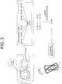
- Fig. 3 is a drawing schematically illustrating how the subject vehicle is rotated by a specific steering angle corresponding to a subject adjusted steering signal, generated from a subject intended steering signal by delivering the steering intention of the autonomous driving module or the driver to the steering apparatus of the subject vehicle more accurately in accordance with one example embodiment of the present disclosure.
- the specific steering angle is 31.84 degrees
- the reference actual steering angles are set as [-60.00, -59.90, -59.80, ... , 59.80, 59.90, 60.00]
- N is two
- the first specific reference steering guide value corresponding to the first specific reference actual steering angle of 31.80 degrees is 33.9 degrees
- the second specific reference steering guide value corresponding to the second specific reference actual steering angle of 31.90 degrees is 34.10 degrees.
- the subject adjusted steering signal for this case may be 33.98 degrees
- the steering apparatus which acquired the subject adjusted steering signal as its input may rotate the subject vehicle by 31.84 degrees.
- the processes corresponding to the steps of S01 and S02 may be performed whenever a trigger corresponding to a start of the subject vehicle is detected.
- the steps of S01 and S02 may be performed whenever the subject vehicle is started.
- the computing device 100 may evaluate the steering apparatus while it generates the reference map. Specifically, the computing device 100 may generate each of steering accuracy scores by referring to each of the reference actual steering angles and its corresponding reference steering guide values.
- each of differences between each of the reference actual steering angles and its corresponding reference steering guide values can be an indicator for a dislocation of the steering apparatus, because the two may be largely different when the steering apparatus has a breakdown.
- the computing device 100 may compare each of the reference actual steering angles and its corresponding reference steering guide values, to thereby generate each of the steering accuracy scores corresponding to each of similarities between each of the reference actual steering angles and its corresponding reference steering guide values.
- the computing device 100 may transmit an alarm to the driver if a ratio of the number of specific steering accuracy scores to the total number of the steering accuracy scores is larger than a first threshold.
- the specific steering accuracy scores, selected among the steering accuracy scores may be smaller than a second threshold. For example, if a ratio of the number of the specific steering accuracy scores which is smaller than 0.95 to the total number is more than 0.1, the alarm may be transmitted.
- the present disclosure has an effect of providing a method for delivering a steering intention of an autonomous driving module or a driver to a steering apparatus of a subject vehicle more accurately, to thereby improve a credibility of an autonomous driving.
- the present disclosure has another of providing a method for generating a reference map to be used for delivering the steering intention of the autonomous driving module or the driver to the steering apparatus of the subject vehicle more accurately.
- the present disclosure has still another effect of alerting the driver to a possible breakdown of the steering apparatus while delivering the steering intention of the autonomous driving module or the driver to the steering apparatus of the subject vehicle more accurately.
- the embodiments of the present disclosure as explained above can be implemented in a form of executable program command through a variety of computer means recordable to computer readable media.
- the computer readable media may include solely or in combination, program commands, data files, and data structures.
- the program commands recorded to the media may be components specially designed for the present disclosure or may be usable to a skilled human in a field of computer software.
- Computer readable media include magnetic media such as hard disk, floppy disk, and magnetic tape, optical media such as CD-ROM and DVD, magneto-optical media such as floptical disk and hardware devices such as ROM, RAM, and flash memory specially designed to store and carry out program commands.
- Program commands include not only a machine language code made by a complier but also a high level code that can be used by an interpreter etc., which is executed by a computer.
- the aforementioned hardware device can work as more than a software module to perform the action of the present disclosure and they can do the same in the opposite case.
Abstract
Description
- The present disclosure relates to a method and a device to be used for an autonomous vehicle; and more particularly to the method for delivering a steering intention of an autonomous driving module or a driver to a steering apparatus of a subject vehicle more accurately, and the device using the same.
- Recently, autonomous driving technologies have attracted attention. The autonomous driving technologies refer to technologies that allow an autonomous vehicle to travel safely by collecting and using external information through modules capable of acquiring the external information, such as a sensor and a camera mounted on the vehicle. The autonomous driving technologies have been developed so much that the autonomous vehicle is able to drive hundreds of kilometers without an accident.
- However, there may be a serious flaw in such autonomous driving technologies. That is, if physical characteristics corresponding to parameters used by a network for the autonomous driving are changed and thus if said parameters do not fit the physical characteristics, the autonomous vehicle may not function correctly, even in case the network for the autonomous driving have calculated a correct value. In one example, even in case the network for the autonomous driving inputs the correct value to a steering module, the autonomous vehicle may not be turned correctly if an angle of the steering module is distorted.
- However, only how to calculate the correct value has been studied, and ways to solve the problem as shown above has not been studied much.
- It is an object of the present disclosure to solve all the aforementioned problems.
- It is another object of the present disclosure to provide a method for delivering a steering intention of an autonomous driving module or a driver to a steering apparatus of a subject vehicle more accurately, to thereby improve a credibility of an autonomous driving.
- It is still another object of the present disclosure to provide a method for generating a reference map to be used for delivering the steering intention of the autonomous driving module or the driver to the steering apparatus of the subject vehicle more accurately.
- It is still yet another object of the present disclosure to alert the driver to a possible breakdown of the steering apparatus while delivering the steering intention of the autonomous driving module or the driver to the steering apparatus of the subject vehicle more accurately.
- In accordance with one aspect of the present disclosure, there is provided a method for delivering a steering intention of an autonomous driving module or a driver to a steering apparatus of a subject vehicle more accurately by using a reference map which is a rule-set generated by referring to past driving records of the subject vehicle, including steps of: (a) a computing device, if a subject intended steering signal included in a subject control signal inputted by the autonomous driving module or the driver at a current timing is acquired, instructing a signal adjustment module to select, by referring to the reference map generated by using past adjusted steering signals and past actual steered angles included in the past driving records, one or more specific reference steering guide values, among reference steering guide values of the reference map, corresponding to the subject intended steering signal; and (b) the computing device (i) adjusting the subject intended steering signal by referring to the specific reference steering guide values, in order to generate a subject adjusted steering signal, and (ii) transmitting the subject adjusted steering signal to the steering apparatus, to thereby support the steering apparatus to rotate the subject vehicle by a specific steering angle corresponding to the subject intended steering signal, which has been intended by the autonomous driving module or the driver.
- As one example, the method, before the step of (a), further includes a step of: (a0) the computing device (i) generating a first vector including information on the past adjusted steering signals, a second vector including information on the past actual steered angles, and a third vector including information on prescribed reference actual steering angles, (ii) performing a regression operation by using the first, the second, and the third vectors, and (iii) generating the reference map including information on (iii-1) the reference steering guide values generated by the regression operation, (iii-2) the reference actual steering angles and (iii-3) a relationship between the reference steering guide values and the reference actual steering angles.
- As one example, at the step of (a0), the computing device performs the regression operation by using a following formula to generate the reference steering guide values:

- As one example, the past adjusted steering signals have been acquired by using past control signals transmitted by the autonomous driving module or the driver for a prescribed time range from a certain past timing to the current timing, and wherein the past actual steered angles are acquired by analyzing a motion of the subject vehicle performed during said time range through at least one of a computer vision module and a steering detection sensor which interwork with the computing device.
- As one example, the method further includes a step of: (a1) the computing device generating each of steering accuracy scores by referring to each of the reference actual steering angles and its corresponding reference steering guide values, and determining whether to transmit an alarm on the steering apparatus to the driver or not by referring to the steering accuracy scores.
- As one example, at the step of (a1), the computing device compares sizes of each of the reference actual steering angles and its corresponding reference steering guide values, to thereby generate each of the steering accuracy scores corresponding to each of similarities between each of the reference actual steering angles and its corresponding reference steering guide values, and transmits the alarm if a ratio of the number of specific steering accuracy scores to the total number of the steering accuracy scores is larger than a first threshold, wherein the specific steering accuracy scores, selected among the steering accuracy scores, are smaller than a second threshold.
- As one example, performs processes corresponding to the steps of (a0) and (a1) if a trigger corresponding to a start of the subject vehicle is detected.
- As one example, at the step of (a), the computing device instructs the signal adjustment module to (i) calculate similarity scores between the reference actual steering angles and the subject intended steering signal by referring to the subject intended steering signal representing the specific steering angle, (ii) find a first to an N-th specific reference actual steering angles corresponding to specific similarity scores which are the top N ones among the similarity scores, and (iii) find a first to an N-th specific reference steering guide values corresponding to the first to the N-th specific reference actual steering angles by referring to information on relationships between the reference actual steering angles and its corresponding reference steering guide values, and wherein, at the step of (b), the computing device performs a linear interpolation by referring to the first to the N-th specific reference actual steering angles and their corresponding first to the N-th specific reference steering guide values, to thereby generate the subject adjusted steering signal.
- In accordance with still another aspect of the present disclosure, there is provided a computing device for delivering a steering intention of an autonomous driving module or a driver to a steering apparatus of a subject vehicle more accurately by using a reference map which is a rule-set generated by referring to past driving records of the subject vehicle, including: at least one memory that stores instructions; and at least one processor configured to execute the instructions to perform processes of: (I) if a subject intended steering signal included in a subject control signal inputted by the autonomous driving module or the driver at a current timing is acquired, instructing a signal adjustment module to select, by referring to the reference map generated by using past adjusted steering signals and past actual steered angles included in the past driving records, one or more specific reference steering guide values, among reference steering guide values of the reference map, corresponding to the subject intended steering signal; and (II) (i) adjusting the subject intended steering signal by referring to the specific reference steering guide values, in order to generate a subject adjusted steering signal, and (ii) transmitting the subject adjusted steering signal to the steering apparatus, to thereby support the steering apparatus to rotate the subject vehicle by a specific steering angle corresponding to the subject intended steering signal, which has been intended by the autonomous driving module or the driver.
- As one example, before the process of (I), the processor further performs a process of: (I0) (i) generating a first vector including information on the past adjusted steering signals, a second vector including information on the past actual steered angles, and a third vector including information on prescribed reference actual steering angles, (ii) performing a regression operation by using the first, the second, and the third vectors, and (iii) generating the reference map including information on (iii-1) the reference steering guide values generated by the regression operation, (iii-2) the reference actual steering angles and (iii-3) a relationship between the reference steering guide values and the reference actual steering angles.
- As one example, at the process of (10), the processor performs the regression operation by using a following formula to generate the reference steering guide values:

- As one example, the past adjusted steering signals have been acquired by using past control signals transmitted by the autonomous driving module or the driver for a prescribed time range from a certain past timing to the current timing, and wherein the past actual steered angles are acquired by analyzing a motion of the subject vehicle performed during said time range through at least one of a computer vision module and a steering detection sensor which interwork with the computing device.
- As one example, the processor further performs a process of: (I1) generating each of steering accuracy scores by referring to each of the reference actual steering angles and its corresponding reference steering guide values, and determining whether to transmit an alarm on the steering apparatus to the driver or not by referring to the steering accuracy scores.
- As one example, at the process of (11), the processor compares sizes of each of the reference actual steering angles and its corresponding reference steering guide values, to thereby generate each of the steering accuracy scores corresponding to each of similarities between each of the reference actual steering angles and its corresponding reference steering guide values, and transmits the alarm if a ratio of the number of specific steering accuracy scores to the total number of the steering accuracy scores is larger than a first threshold, wherein sizes of the specific steering accuracy scores, selected among the steering accuracy scores, are smaller than a second threshold.
- As one example, the processor performs the processes of (I0) and (I1) if a trigger corresponding to a start of the subject vehicle is detected.
- As one example, at the process of (I), the processor instructs the signal adjustment module to (i) calculate similarity scores between the reference actual steering angles and the subject intended steering signal by referring to the subject intended steering signal representing the specific steering angle, (ii) find a first to an N-th specific reference actual steering angles corresponding to specific similarity scores which are the top N ones among the similarity scores, and (iii) find a first to an N-th specific reference steering guide values corresponding to the first to the N-th specific reference actual steering angles by referring to information on relationships between the reference actual steering angles and its corresponding reference steering guide values, and wherein, at the process of (II), the processor performs a linear interpolation by referring to the first to the N-th specific reference actual steering angles and their corresponding first to the N-th specific reference steering guide values, to thereby generate the subject adjusted steering signal.
- In addition, recordable media that are readable by a computer for storing a computer program to execute the method of the present disclosure is further provided.
- The above and other objects and features of the present disclosure will become apparent from the following description of preferred embodiments given in conjunction with the accompanying drawings.
-
Fig. 1 is a drawing schematically illustrating a configuration of a computing device performing a method for delivering a steering intention of an autonomous driving module or a driver to a steering apparatus of a subject vehicle more accurately in accordance with one example embodiment of the present disclosure. -
Fig. 2 is a drawing schematically illustrating a flow of the method for delivering the steering intention of the autonomous driving module or the driver to the steering apparatus of the subject vehicle more accurately in accordance with one example embodiment of the present disclosure. -
Fig. 3 is a drawing schematically illustrating how the subject vehicle is rotated by a specific steering angle corresponding to a subject adjusted steering signal, generated from a subject intended steering signal by delivering the steering intention of the autonomous driving module or the driver to the steering apparatus of the subject vehicle more accurately in accordance with one example embodiment of the present disclosure. - Detailed explanation on the present disclosure to be made below refer to attached drawings and diagrams illustrated as specific embodiment examples under which the present disclosure may be implemented to make clear of purposes, technical solutions, and advantages of the present disclosure. These embodiments are described in sufficient detail to enable those skilled in the art to practice the disclosure.
- Besides, in the detailed description and claims of the present disclosure, a term "include" and its variations are not intended to exclude other technical features, additions, components or steps. Other objects, benefits and features of the present disclosure will be revealed to one skilled in the art, partially from the specification and partially from the implementation of the present disclosure. The following examples and drawings will be provided as examples but they are not intended to limit the present disclosure.
- Moreover, the present disclosure covers all possible combinations of example embodiments indicated in this specification. It is to be understood that the various embodiments of the present disclosure, although different, are not necessarily mutually exclusive. For example, a particular feature, structure, or characteristic described herein in connection with one embodiment may be implemented within other embodiments without departing from the spirit and scope of the present disclosure. In addition, it is to be understood that the position or arrangement of individual elements within each disclosed embodiment may be modified without departing from the spirit and scope of the present disclosure. The following detailed description is, therefore, not to be taken in a limiting sense, and the scope of the present disclosure is defined only by the appended claims, appropriately interpreted, along with the full range of equivalents to which the claims are entitled. In the drawings, like numerals refer to the same or similar functionality throughout the several views.
- Any images referred to in the present disclosure may include images related to any roads paved or unpaved, in which case the objects on the roads or near the roads may include vehicles, persons, animals, plants, buildings, flying objects like planes or drones, or any other obstacles which may appear in a road-related scene, but the scope of the present disclosure is not limited thereto. As another example, said any images referred to in the present disclosure may include images not related to any roads, such as images related to alleyway, land lots, sea, lakes, rivers, mountains, forests, deserts, sky, or any indoor space, in which case the objects in said any images may include vehicles, persons, animals, plants, buildings, flying objects like planes or drones, ships, amphibious planes or ships, or any other obstacles which may appear in a scene related to alleyway, land lots, sea, lakes, rivers, mountains, forests, deserts, sky, or any indoor space, but the scope of the present disclosure is not limited thereto.
- To allow those skilled in the art to carry out the present disclosure easily, the example embodiments of the present disclosure by referring to attached diagrams will be explained in detail as shown below.
-
Fig. 1 is a drawing schematically illustrating a configuration of a computing device performing a method for delivering a steering intention of an autonomous driving module or a driver to a steering apparatus of a subject vehicle more accurately in accordance with one example embodiment of the present disclosure. - By referring to
Fig. 1 , thecomputing device 100 may include asignal adjustment module 130 to be described later. Processes of input/output and computations of thesignal adjustment module 130 may be respectively performed by at least onecommunication part 110 and at least oneprocessor 120. However, detailed communication schematics between thecommunication part 110 and theprocessor 120 are omitted inFig. 1 . Herein, amemory 115 may have stored various instructions to be described later, and theprocessor 120 may execute the instructions stored in thememory 115 and may perform processes of the present disclosure by executing the instructions to be disclosed later. Such description of thecomputing device 100 does not exclude an integrated device including any combination of a processor, a memory, a medium, or any other computing components. - So far the configuration of the
computing device 100 performing the method for delivering the steering intention of the autonomous driving module or the driver to the steering apparatus of the subject vehicle more accurately in accordance with one example embodiment of the present disclosure has been explained. Below, the method itself will be explained more specifically. -
Fig. 2 is a drawing schematically illustrating a flow of the method for delivering the steering intention of the autonomous driving module or the driver to the steering apparatus of the subject vehicle more accurately in accordance with one example embodiment of the present disclosure. - By referring to
Fig. 2 , at a step of S01, thecomputing device 100 may generate a reference map by using one or more past adjusted steering signals and one or more past actual steered angles. And, at a step of S02, thecomputing device 100, if a subject intended steering signal is acquired, may instruct thesignal adjustment module 130 to find one or more specific reference steering guide values corresponding to the subject intended steering signal by referring to the reference map. Then, at a step of S03, thecomputing device 100 may transmit a subject adjusted steering signal to the steering apparatus, generated by using the specific reference steering guide values, to thereby support the steering apparatus to rotate the subject vehicle by a specific steering angle corresponding to the subject intended steering signal. - So far a brief flow of the method has been explained. Below, it will be explained more specifically.
- First, the method of the present disclosure is directed to a method for ensuring the subject vehicle to be turned as the intention of the autonomous driving module or the driver, even though the steering apparatus of the subject vehicle malfunctions due to internal or external factors, by using the reference map. Herein, the reference map may be configured as a table. Such reference map may be generated by referring to the past adjusted steering signals inputted to the steering apparatus of the subject vehicle and the past actual steered angles which denote real angles of the subject vehicle being actually rotated when the past adjusted steering signals are inputted, included in the past driving records. As one example, a specific past adjusted steering signal may have been inputted to the steering apparatus to rotate the subject vehicle by 32 degrees but the subject vehicle has been rotated by 30 degrees so that its corresponding specific past actual steered angle may denote a rotation by 30 degrees. Such difference between the two angles may have been caused by a breakdown of the steering apparatus.
- The past adjusted steering signals and the past actual steered angles may have been detected and stored during a prescribed time range from a certain past timing to the current timing. The past adjusted steering signals may have been detected by analyzing past control signals internally transmitted from the autonomous driving module or the driver, and the past actual steered angles may have been detected by analyzing a motion of the subject vehicle performed during said prescribed time range, through at least one of a computer vision module and a steering detection sensor, which interworks with the
computing device 100. More specifically, the past actual steered angles may not be acquired by analyzing internal signals, different from the past adjusted steering signals. That is, those may be acquired by using external sensors such as the computer vision module and the steering detection sensor. The computer vision module may interwork with a camera on the subject vehicle and calculate an angle of a rotation of the subject vehicle by analyzing an image acquired through the camera, using a well-known angle calculation schemes. Otherwise, the steering detection sensor may be installed on the steering apparatus as a physical external sensor, to detect an angle of a rotation of wheels. - The past adjusted steering signals and the past actual steered angles may be additionally processed in order to be used for generating the reference map. Such additional process may represent a process of finding information on general relationships between reference steering guide values and reference actual steering angles by using the past adjusted steering signals and the past actual steered angles. Herein, the reference steering guide values may represent signals to be inputted to the steering apparatus, and the reference actual steering angles may represent actual steered angles expected when said signals are inputted thereto.
- Herein, the reference steering guide values may denote values to be inputted to the steering apparatus to make the subject vehicle to rotate by their corresponding reference actual steering angles. As one example, if the subject vehicle is to be rotated by 30 degrees when a signal representing a rotation of 32 degrees is inputted to the steering apparatus, a specific reference actual steering angle of 32 degrees may correspond to a specific reference steering guide value of 30 degrees.
- Herein, someone may question why relationships between the past adjusted steering signals and the past actual steered angles are not used directly, even though the relationships between those two are already acquired without the additional process. Those cannot used directly because the past adjusted steering signals and the past actual steered angles cannot cover all general possible cases. For example, if the subject intended steering signal corresponds to an angle which is not included in the past actual steered angles, the subject intended steering signal may not be adjusted properly. Thus, in order to cover the all possible cases, the past adjusted steering signals and the past actual steered angles should be additionally processed in order to generate the reference map. To be simple, the additional process may be performed to find the general relationships by using specific relationships acquired during the prescribed time range.
- Meanwhile, the reference actual steering angles may have been set by a manager to cover all angles expected to be intended by the autonomous driving module or the driver. As one example, it may have been set as [-60.00, -59.90, -59.80, ... , 59.80,59.90,60.00], covering a range between - 60 degrees and 60 degrees at 0.1 degree intervals. Such range and the intervals may be determined by the manager from the beginning. Otherwise, the reference actual steering angles may be set continuously, not discretely as shown above, but a scope of the present disclosure may not be limited thereto.
- Under an assumption stated above, the
computing device 100 may perform a regression operation, e.g., a Gaussian Process Regression(GP Regression), to generate the reference steering guide values by using a following formula:
- Herein, Θ pastsignal may denote a first vector including information on the past adjusted steering signals and Θ pastangle may denote a second vector including information on the past actual steered angles. Also, Θ refangle may denote a third vector including information on said prescribed reference actual steering angles, and Θ refsignal may denote a fourth vector including information on the reference steering guide values. Further, K(Θ1, Θ2) may denote an output of a kernel function for two input vectors Θ1 and Θ2, and σn may denote estimated standard deviations of noises of the past actual steered angles. As one example, the kernel function may be given as

- The reference steering guide values can be determined by using the formula owing to characteristics of the GP regression. The GP regression is a regression operation for estimating a function value of an input x ∈ RN by using a given data set including information on xi ∈ RN and its corresponding function values yi ∈ RM in a form of a probability distribution. Herein, xi ∈ RN may correspond to the past actual steered angles, yi ∈ RM may correspond to the past adjusted steering signals, x ∈ RN may correspond to the reference actual steered angles, and averages of the probability distribution to be used for estimating the function values of the reference actual steered angles may be the reference steering guide values. By performing the GP regression as shown above, the relationships between the reference steering guide values and the reference actual steered values may be found.
- For reference, the formula for the GP regression can be deducted from a following formula:

- A mathematical basis of the above processes is a thesis named "Gaussian Process for Machine Learning" of Rasmussen et al., 2016. By referring to the thesis, a person in the art may understand the present disclosure which is a practical application of contents of the thesis. Also, the person in the art may easily deduct a method for generating more various reference steering guide values by further using variances of the probability distributions, from the present disclosure using only averages thereof, thus such embodiment is included in the scope of the present disclosure.
- After the reference map is generated, the
computing device 100 may instruct thesignal adjustment module 130 to select one or more specific reference steering guide values, among reference steering guide values of the reference map, corresponding to the subject intended steering signal, by referring to the subject intended steering signal corresponding to the specific steering angle. - More specifically, the
computing device 100 may instruct thesignal adjustment module 130 to (i) calculate similarity scores between the reference actual steering angles and the subject intended steering signal by referring to the subject intended steering signal representing the specific steering angle, (ii) find a first to an N-th specific reference actual steering angles corresponding to specific similarity scores which are the top N ones among the similarity scores. Herein, a specific similarity score may be calculated by (i) comparing a size of the specific steering angle and a size of a specific reference actual steering angle, and (ii) setting one with larger size at a denominator and the other one with smaller size at a numerator. The whole similarity scores may be calculated similarly to the specific similarity score. Otherwise, as a simple approach, when N is 2, one of the reference steering guide values which is the smallest among ones larger than the specific steering angle may be set as a first specific reference steering guide value, and the other one of the reference steering guide values which is the largest among ones smaller than the specific steering angle may be set as a second specific reference steering guide value. - Thereafter, the
computing device 100 may perform a linear interpolation by referring to the first to the N-th specific reference actual steering angles and their corresponding first to the N-th specific reference steering guide values, to thereby generate the subject adjusted steering signal. To explain such process,Fig. 3 will be referred to. -
Fig. 3 is a drawing schematically illustrating how the subject vehicle is rotated by a specific steering angle corresponding to a subject adjusted steering signal, generated from a subject intended steering signal by delivering the steering intention of the autonomous driving module or the driver to the steering apparatus of the subject vehicle more accurately in accordance with one example embodiment of the present disclosure. - By referring to
Fig. 3 , it can be seen that the specific steering angle is 31.84 degrees, the reference actual steering angles are set as [-60.00, -59.90, -59.80, ... , 59.80, 59.90, 60.00], N is two, the first specific reference steering guide value corresponding to the first specific reference actual steering angle of 31.80 degrees is 33.9 degrees, the second specific reference steering guide value corresponding to the second specific reference actual steering angle of 31.90 degrees is 34.10 degrees. In this case, the linear interpolation may be performed as shown below:
- Herein, the subject adjusted steering signal for this case may be 33.98 degrees, and the steering apparatus which acquired the subject adjusted steering signal as its input may rotate the subject vehicle by 31.84 degrees.
- Below, some additional configurations of the present disclosure will be explained.
- First, the processes corresponding to the steps of S01 and S02 may be performed whenever a trigger corresponding to a start of the subject vehicle is detected. To be simple, the steps of S01 and S02 may be performed whenever the subject vehicle is started.
- Also, the
computing device 100 may evaluate the steering apparatus while it generates the reference map. Specifically, thecomputing device 100 may generate each of steering accuracy scores by referring to each of the reference actual steering angles and its corresponding reference steering guide values. Herein, each of differences between each of the reference actual steering angles and its corresponding reference steering guide values can be an indicator for a dislocation of the steering apparatus, because the two may be largely different when the steering apparatus has a breakdown. Accordingly, thecomputing device 100 may compare each of the reference actual steering angles and its corresponding reference steering guide values, to thereby generate each of the steering accuracy scores corresponding to each of similarities between each of the reference actual steering angles and its corresponding reference steering guide values. - Thereafter, the
computing device 100 may transmit an alarm to the driver if a ratio of the number of specific steering accuracy scores to the total number of the steering accuracy scores is larger than a first threshold. Herein, the specific steering accuracy scores, selected among the steering accuracy scores, may be smaller than a second threshold. For example, if a ratio of the number of the specific steering accuracy scores which is smaller than 0.95 to the total number is more than 0.1, the alarm may be transmitted. - The present disclosure has an effect of providing a method for delivering a steering intention of an autonomous driving module or a driver to a steering apparatus of a subject vehicle more accurately, to thereby improve a credibility of an autonomous driving.
- The present disclosure has another of providing a method for generating a reference map to be used for delivering the steering intention of the autonomous driving module or the driver to the steering apparatus of the subject vehicle more accurately.
- The present disclosure has still another effect of alerting the driver to a possible breakdown of the steering apparatus while delivering the steering intention of the autonomous driving module or the driver to the steering apparatus of the subject vehicle more accurately.
- The embodiments of the present disclosure as explained above can be implemented in a form of executable program command through a variety of computer means recordable to computer readable media. The computer readable media may include solely or in combination, program commands, data files, and data structures. The program commands recorded to the media may be components specially designed for the present disclosure or may be usable to a skilled human in a field of computer software. Computer readable media include magnetic media such as hard disk, floppy disk, and magnetic tape, optical media such as CD-ROM and DVD, magneto-optical media such as floptical disk and hardware devices such as ROM, RAM, and flash memory specially designed to store and carry out program commands. Program commands include not only a machine language code made by a complier but also a high level code that can be used by an interpreter etc., which is executed by a computer. The aforementioned hardware device can work as more than a software module to perform the action of the present disclosure and they can do the same in the opposite case.
- As seen above, the present disclosure has been explained by specific matters such as detailed components, limited embodiments, and drawings. They have been provided only to help more general understanding of the present disclosure. It, however, will be understood by those skilled in the art that various changes and modification may be made from the description without departing from the spirit and scope of the disclosure as defined in the following claims.
- Accordingly, the thought of the present disclosure must not be confined to the explained embodiments, and the following patent claims as well as everything including variations equal or equivalent to the patent claims pertain to the category of the thought of the present disclosure.
Claims (15)
- A method for delivering a steering intention of an autonomous driving module or a driver to a steering apparatus of a subject vehicle more accurately by using a reference map which is a rule-set generated by referring to past driving records of the subject vehicle, comprising steps of:(a) a computing device, if a subject intended steering signal included in a subject control signal inputted by the autonomous driving module or the driver at a current timing is acquired, instructing a signal adjustment module to select, by referring to the reference map generated by using past adjusted steering signals and past actual steered angles included in the past driving records, one or more specific reference steering guide values, among reference steering guide values of the reference map, corresponding to the subject intended steering signal; and(b) the computing device (i) adjusting the subject intended steering signal by referring to the specific reference steering guide values, in order to generate a subject adjusted steering signal, and (ii) transmitting the subject adjusted steering signal to the steering apparatus, to thereby support the steering apparatus to rotate the subject vehicle by a specific steering angle corresponding to the subject intended steering signal, which has been intended by the autonomous driving module or the driver.
- The method of Claim 1, before the step of (a), further comprising a step of:
(a0) the computing device (i) generating a first vector including information on the past adjusted steering signals, a second vector including information on the past actual steered angles, and a third vector including information on prescribed reference actual steering angles, (ii) performing a regression operation by using the first, the second, and the third vectors, and (iii) generating the reference map including information on (iii-1) the reference steering guide values generated by the regression operation, (iii-2) the reference actual steering angles and (iii-3) a relationship between the reference steering guide values and the reference actual steering angles. - The method of Claim 2, wherein, at the step of (a0), the computing device performs the regression operation by using a following formula to generate the reference steering guide values:

- The method of Claim 2, wherein the past adjusted steering signals have been acquired by using past control signals transmitted by the autonomous driving module or the driver for a prescribed time range from a certain past timing to the current timing, and wherein the past actual steered angles are acquired by analyzing a motion of the subject vehicle performed during said time range through at least one of a computer vision module and a steering detection sensor which interworks with the computing device.
- The method of Claim 2, further comprising a step of:
(a1) the computing device generating each of steering accuracy scores by referring to each of the reference actual steering angles and its corresponding reference steering guide values, and determining whether to transmit an alarm on the steering apparatus to the driver or not by referring to the steering accuracy scores. - The method of Claim 5, wherein, at the step of (a1), the computing device compares sizes of each of the reference actual steering angles and its corresponding reference steering guide values, to thereby generate each of the steering accuracy scores corresponding to each of similarities between each of the reference actual steering angles and its corresponding reference steering guide values, and transmits the alarm if a ratio of the number of specific steering accuracy scores to the total number of the steering accuracy scores is larger than a first threshold, wherein the specific steering accuracy scores, selected among the steering accuracy scores, are smaller than a second threshold.
- The method of Claim 5, the computing device performs processes corresponding to the steps of (a0) and (a1) if a trigger corresponding to a start of the subject vehicle is detected.
- The method of Claim 1, wherein, at the step of (a), the computing device instructs the signal adjustment module to (i) calculate similarity scores between the reference actual steering angles and the subject intended steering signal by referring to the subject intended steering signal representing the specific steering angle, (ii) find a first to an N-th specific reference actual steering angles corresponding to specific similarity scores which are the top N ones among the similarity scores, and (iii) find a first to an N-th specific reference steering guide values corresponding to the first to the N-th specific reference actual steering angles by referring to information on relationships between the reference actual steering angles and its corresponding reference steering guide values, and
wherein, at the step of (b), the computing device performs a linear interpolation by referring to the first to the N-th specific reference actual steering angles and their corresponding first to the N-th specific reference steering guide values, to thereby generate the subject adjusted steering signal. - A computing device for delivering a steering intention of an autonomous driving module or a driver to a steering apparatus of a subject vehicle more accurately by using a reference map which is a rule-set generated by referring to past driving records of the subject vehicle, comprising:at least one memory that stores instructions; andat least one processor configured to execute the instructions to perform processes of: (I) if a subject intended steering signal included in a subject control signal inputted by the autonomous driving module or the driver at a current timing is acquired, instructing a signal adjustment module to select, by referring to the reference map generated by using past adjusted steering signals and past actual steered angles included in the past driving records, one or more specific reference steering guide values, among reference steering guide values of the reference map, corresponding to the subject intended steering signal; and (II) (i) adjusting the subject intended steering signal by referring to the specific reference steering guide values, in order to generate a subject adjusted steering signal, and (ii) transmitting the subject adjusted steering signal to the steering apparatus, to thereby support the steering apparatus to rotate the subject vehicle by a specific steering angle corresponding to the subject intended steering signal, which has been intended by the autonomous driving module or the driver.
- The computing device of Claim 9, wherein, before the process of (I), the processor further performs a process of:
(I0) (i) generating a first vector including information on the past adjusted steering signals, a second vector including information on the past actual steered angles, and a third vector including information on prescribed reference actual steering angles, (ii) performing a regression operation by using the first, the second, and the third vectors, and (iii) generating the reference map including information on (iii-1) the reference steering guide values generated by the regression operation, (iii-2) the reference actual steering angles and (iii-3) a relationship between the reference steering guide values and the reference actual steering angles. - The computing device of Claim 10, wherein, at the process of (10), the processor performs the regression operation by using a following formula to generate the reference steering guide values:

- The computing device of Claim 10, wherein the past adjusted steering signals have been acquired by using past control signals transmitted by the autonomous driving module or the driver for a prescribed time range from a certain past timing to the current timing, and wherein the past actual steered angles are acquired by analyzing a motion of the subject vehicle performed during said time range through at least one of a computer vision module and a steering detection sensor which interworks with the computing device.
- The computing device of Claim 10, wherein the processor further performs a process of:
(I1) generating each of steering accuracy scores by referring to each of the reference actual steering angles and its corresponding reference steering guide values, and determining whether to transmit an alarm on the steering apparatus to the driver or not by referring to the steering accuracy scores. - The computing device of Claim 13, wherein, at the process of (11), the processor compares sizes of each of the reference actual steering angles and its corresponding reference steering guide values, to thereby generate each of the steering accuracy scores corresponding to each of similarities between each of the reference actual steering angles and its corresponding reference steering guide values, and transmits the alarm if a ratio of the number of specific steering accuracy scores to the total number of the steering accuracy scores is larger than a first threshold, wherein the specific steering accuracy scores, selected among the steering accuracy scores, are smaller than a second threshold.
- The computing device of Claim 9, wherein, at the process of (I), the processor instructs the signal adjustment module to (i) calculate similarity scores between the reference actual steering angles and the subject intended steering signal by referring to the subject intended steering signal representing the specific steering angle, (ii) find a first to an N-th specific reference actual steering angles corresponding to specific similarity scores which are the top N ones among the similarity scores, and (iii) find a first to an N-th specific reference steering guide values corresponding to the first to the N-th specific reference actual steering angles by referring to information on relationships between the reference actual steering angles and its corresponding reference steering guide values, and
wherein, at the process of (II), the processor performs a linear interpolation by referring to the first to the N-th specific reference actual steering angles and their corresponding first to the N-th specific reference steering guide values, to thereby generate the subject adjusted steering signal.
Applications Claiming Priority (2)
| Application Number | Priority Date | Filing Date | Title |
|---|---|---|---|
| US201962799407P | 2019-01-31 | 2019-01-31 | |
| US16/740,213 US10843728B2 (en) | 2019-01-31 | 2020-01-10 | Method and device for delivering steering intention of autonomous driving module or driver to steering apparatus of subject vehicle more accurately |
Publications (2)
| Publication Number | Publication Date |
|---|---|
| EP3689708A1 true EP3689708A1 (en) | 2020-08-05 |
| EP3689708B1 EP3689708B1 (en) | 2022-06-01 |
Family
ID=69187607
Family Applications (1)
| Application Number | Title | Priority Date | Filing Date |
|---|---|---|---|
| EP20153038.3A Active EP3689708B1 (en) | 2019-01-31 | 2020-01-22 | Method and device for delivering steering intention of autonomous driving module or driver to steering apparatus of subject vehicle more accurately |
Country Status (5)
| Country | Link |
|---|---|
| US (1) | US10843728B2 (en) |
| EP (1) | EP3689708B1 (en) |
| JP (1) | JP6921443B2 (en) |
| KR (1) | KR102280417B1 (en) |
| CN (1) | CN111497939B (en) |
Families Citing this family (1)
| Publication number | Priority date | Publication date | Assignee | Title |
|---|---|---|---|---|
| CN113891048B (en) * | 2021-10-28 | 2022-11-15 | 江苏濠汉信息技术有限公司 | Over-sight distance image transmission system for rail locomotive |
Citations (2)
| Publication number | Priority date | Publication date | Assignee | Title |
|---|---|---|---|---|
| US20110040446A1 (en) * | 2007-08-27 | 2011-02-17 | Toyota Jidosha Kabushiki Kaisha | Steering control device |
| US20180281845A1 (en) * | 2017-03-30 | 2018-10-04 | Ford Global Technologies, Llc | Methods and apparatus to correct clear vision errors in a vehicle steering system |
Family Cites Families (36)
| Publication number | Priority date | Publication date | Assignee | Title |
|---|---|---|---|---|
| JPS6032043B2 (en) * | 1977-06-03 | 1985-07-25 | 三輪精機株式会社 | Multi-speed hydraulic drive |
| JP2715555B2 (en) * | 1989-06-13 | 1998-02-18 | トヨタ自動車株式会社 | Steering linked headlight system for vehicles |
| JPH08282510A (en) * | 1995-04-17 | 1996-10-29 | Koyo Seiko Co Ltd | Power steering device |
| JP5135722B2 (en) * | 2006-06-19 | 2013-02-06 | 株式会社ジェイテクト | Vehicle steering system |
| JP5086582B2 (en) * | 2006-08-09 | 2012-11-28 | 本田技研工業株式会社 | Steering control system and steering control program |
| DE102008002699A1 (en) * | 2008-06-27 | 2009-12-31 | Robert Bosch Gmbh | An apparatus and method for controlling automatic steering of a vehicle, and apparatus and method for checking a feasibility of a predetermined target heading for a vehicle |
| CN102612456B (en) * | 2010-04-14 | 2014-12-31 | 丰田自动车株式会社 | Vehicle control device |
| JP5893498B2 (en) * | 2012-04-26 | 2016-03-23 | 日立オートモティブシステムズステアリング株式会社 | Power steering device and control device for power steering device |
| US9623901B2 (en) * | 2012-10-04 | 2017-04-18 | Nissan Motor Co., Ltd. | Steering control device |
| US9567003B2 (en) * | 2012-11-07 | 2017-02-14 | Nissan Motor Co., Ltd. | Steering control device |
| KR102002334B1 (en) * | 2012-11-20 | 2019-07-23 | 현대모비스 주식회사 | Lane Keeping Assist Apparatus |
| JP6032043B2 (en) * | 2013-02-13 | 2016-11-24 | 日産自動車株式会社 | Vehicle steering control device and vehicle steering control method |
| WO2014128818A1 (en) * | 2013-02-21 | 2014-08-28 | 日産自動車株式会社 | Vehicular steering control device, and vehicular steering control method |
| JP6142659B2 (en) * | 2013-05-13 | 2017-06-07 | 日産自動車株式会社 | Vehicle steering control device and vehicle steering control method |
| JP5530020B1 (en) * | 2013-11-01 | 2014-06-25 | 株式会社日立パワーソリューションズ | Abnormality diagnosis system and abnormality diagnosis method |
| JP6322023B2 (en) * | 2014-03-28 | 2018-05-09 | 株式会社Subaru | Measuring device and failure diagnosis device using the same |
| JP2016222180A (en) * | 2015-06-02 | 2016-12-28 | 富士重工業株式会社 | Vehicle steering control device |
| JP2017077830A (en) * | 2015-10-21 | 2017-04-27 | Kyb株式会社 | Electric power steering device |
| JP6198181B2 (en) * | 2015-11-06 | 2017-09-20 | マツダ株式会社 | Vehicle behavior control device |
| WO2018008628A1 (en) * | 2016-07-05 | 2018-01-11 | 日本精工株式会社 | Detection device and electric power steering device |
| JP6270251B1 (en) * | 2016-09-21 | 2018-01-31 | マツダ株式会社 | Vehicle behavior control device |
| US11046332B2 (en) * | 2016-11-09 | 2021-06-29 | Honda Motor Co., Ltd. | Vehicle control device, vehicle control system, vehicle control method, and storage medium |
| US9874871B1 (en) * | 2016-11-21 | 2018-01-23 | Baidu Usa Llc | Method to dynamically adjusting steering rates of autonomous vehicles |
| CN110461680B (en) * | 2017-03-29 | 2023-06-23 | 提爱思科技股份有限公司 | Vehicle control system |
| US10569784B2 (en) * | 2017-09-28 | 2020-02-25 | Waymo Llc | Detecting and responding to propulsion and steering system errors for autonomous vehicles |
| US10591914B2 (en) * | 2017-11-08 | 2020-03-17 | GM Global Technology Operations LLC | Systems and methods for autonomous vehicle behavior control |
| US10845803B2 (en) * | 2017-11-29 | 2020-11-24 | Nio Usa, Inc. | Method and apparatus for simultaneous processing and logging of automotive vision system with controls and fault monitoring |
| US20190163176A1 (en) * | 2017-11-30 | 2019-05-30 | drive.ai Inc. | Method for transferring control of an autonomous vehicle to a remote operator |
| US11525688B2 (en) * | 2017-12-15 | 2022-12-13 | Samsung Electronics Co., Ltd. | Method and apparatus for determining object position |
| US20190185010A1 (en) * | 2017-12-18 | 2019-06-20 | PlusAI Corp | Method and system for self capability aware route planning in autonomous driving vehicles |
| US11126199B2 (en) * | 2018-04-16 | 2021-09-21 | Baidu Usa Llc | Learning based speed planner for autonomous driving vehicles |
| US10908609B2 (en) * | 2018-04-30 | 2021-02-02 | Toyota Research Institute, Inc. | Apparatus and method for autonomous driving |
| US20180348771A1 (en) * | 2018-07-26 | 2018-12-06 | GM Global Technology Operations LLC | Stop contingency planning during autonomous vehicle operation |
| US10976748B2 (en) * | 2018-08-22 | 2021-04-13 | Waymo Llc | Detecting and responding to sounds for autonomous vehicles |
| US11280625B2 (en) * | 2018-09-07 | 2022-03-22 | Waymo Llc | Ambient lighting conditions for autonomous vehicles |
| US11535262B2 (en) * | 2018-09-10 | 2022-12-27 | Here Global B.V. | Method and apparatus for using a passenger-based driving profile |
-
2020
- 2020-01-10 US US16/740,213 patent/US10843728B2/en active Active
- 2020-01-20 CN CN202010064861.1A patent/CN111497939B/en active Active
- 2020-01-20 KR KR1020200007633A patent/KR102280417B1/en active IP Right Grant
- 2020-01-22 EP EP20153038.3A patent/EP3689708B1/en active Active
- 2020-01-27 JP JP2020011165A patent/JP6921443B2/en active Active
Patent Citations (2)
| Publication number | Priority date | Publication date | Assignee | Title |
|---|---|---|---|---|
| US20110040446A1 (en) * | 2007-08-27 | 2011-02-17 | Toyota Jidosha Kabushiki Kaisha | Steering control device |
| US20180281845A1 (en) * | 2017-03-30 | 2018-10-04 | Ford Global Technologies, Llc | Methods and apparatus to correct clear vision errors in a vehicle steering system |
Also Published As
| Publication number | Publication date |
|---|---|
| EP3689708B1 (en) | 2022-06-01 |
| JP2020125107A (en) | 2020-08-20 |
| CN111497939A (en) | 2020-08-07 |
| JP6921443B2 (en) | 2021-08-18 |
| KR102280417B1 (en) | 2021-07-23 |
| CN111497939B (en) | 2022-12-06 |
| US10843728B2 (en) | 2020-11-24 |
| US20200247469A1 (en) | 2020-08-06 |
| KR20200095380A (en) | 2020-08-10 |
Similar Documents
| Publication | Publication Date | Title |
|---|---|---|
| EP3690712A1 (en) | Learning method and learning device of pedestrian detector for robust surveillance based on image analysis by using gan and testing method and testing device using the same | |
| US10776673B2 (en) | Learning method and learning device for sensor fusion to integrate information acquired by radar capable of distance estimation and information acquired by camera to thereby improve neural network for supporting autonomous driving, and testing method and testing device using the same | |
| EP3690742A1 (en) | Method for auto-labeling training images for use in deep learning network to analyze images with high precision, and auto-labeling device using the same | |
| EP3690795A1 (en) | Method and device for providing information for evaluating driving habits of driver by detecting driving scenarios occurring during driving | |
| US11188089B2 (en) | Localization for autonomous vehicles using gaussian mixture models | |
| US9411035B2 (en) | Method and electronic apparatus for angle estimation verification | |
| US10633007B1 (en) | Autonomous driving assistance glasses that assist in autonomous driving by recognizing humans' status and driving environment through image analysis based on deep neural network | |
| EP3690725A1 (en) | Method and device for seamless parameter switch by using location-specific algorithm selection to achieve optimized autonomous driving in each of regions | |
| US20200239029A1 (en) | Learning method and learning device for determining whether to switch mode of vehicle from manual driving mode to autonomous driving mode by performing trajectory-based behavior analysis on recent driving route | |
| US10635915B1 (en) | Method and device for warning blind spot cooperatively based on V2V communication with fault tolerance and fluctuation robustness in extreme situation | |
| EP3702964A1 (en) | Method for correcting misalignment of camera by selectively using information generated by itself and information generated by other entities and device using the same | |
| EP3690400A1 (en) | Method and device for ego-vehicle localization to update hd map by using v2x information fusion | |
| EP3690716A1 (en) | Method and device for merging object detection information detected by each of object detectors corresponding to each camera nearby for the purpose of collaborative driving by using v2x-enabled applications, sensor fusion via multiple vehicles | |
| US10710599B2 (en) | System and method for online probabilistic change detection in feature-based maps | |
| US11703344B2 (en) | Landmark location estimation apparatus and method, and computer-readable recording medium storing computer program programmed to perform method | |
| EP3690715A1 (en) | Learning method and learning device for switching modes of autonomous vehicle based on on-device standalone prediction to thereby achieve safety of autonomous driving, and testing method and testing device using the same | |
| EP3689708A1 (en) | Method and device for delivering steering intention of autonomous driving module or driver to steering apparatus of subject vehicle more accurately | |
| Albousefi et al. | A support vector machine approach to unintentional vehicle lane departure prediction | |
| EP3690733A1 (en) | Method and device for supporting administrators to evaluate object detecting processes of object detectors to provide logical grounds of autonomous driving | |
| US20220270356A1 (en) | Platform for perception system development for automated driving system | |
| CN116767224B (en) | Method, device, vehicle and storage medium for determining a travelable region | |
| US20230071569A1 (en) | Method and device for monitoring operations of an automated driving system of a vehicle | |
| Riley et al. | Constraint Decision Optimization Model for Safe Autonomous Vehicle Operation |
Legal Events
| Date | Code | Title | Description |
|---|---|---|---|
| PUAI | Public reference made under article 153(3) epc to a published international application that has entered the european phase |
Free format text: ORIGINAL CODE: 0009012 |
|
| STAA | Information on the status of an ep patent application or granted ep patent |
Free format text: STATUS: REQUEST FOR EXAMINATION WAS MADE |
|
| 17P | Request for examination filed |
Effective date: 20200122 |
|
| AK | Designated contracting states |
Kind code of ref document: A1 Designated state(s): AL AT BE BG CH CY CZ DE DK EE ES FI FR GB GR HR HU IE IS IT LI LT LU LV MC MK MT NL NO PL PT RO RS SE SI SK SM TR |
|
| AX | Request for extension of the european patent |
Extension state: BA ME |
|
| RBV | Designated contracting states (corrected) |
Designated state(s): AL AT BE BG CH CY CZ DE DK EE ES FI FR GB GR HR HU IE IS IT LI LT LU LV MC MK MT NL NO PL PT RO RS SE SI SK SM TR |
|
| GRAP | Despatch of communication of intention to grant a patent |
Free format text: ORIGINAL CODE: EPIDOSNIGR1 |
|
| STAA | Information on the status of an ep patent application or granted ep patent |
Free format text: STATUS: GRANT OF PATENT IS INTENDED |
|
| INTG | Intention to grant announced |
Effective date: 20220127 |
|
| GRAS | Grant fee paid |
Free format text: ORIGINAL CODE: EPIDOSNIGR3 |
|
| GRAA | (expected) grant |
Free format text: ORIGINAL CODE: 0009210 |
|
| STAA | Information on the status of an ep patent application or granted ep patent |
Free format text: STATUS: THE PATENT HAS BEEN GRANTED |
|
| AK | Designated contracting states |
Kind code of ref document: B1 Designated state(s): AL AT BE BG CH CY CZ DE DK EE ES FI FR GB GR HR HU IE IS IT LI LT LU LV MC MK MT NL NO PL PT RO RS SE SI SK SM TR |
|
| REG | Reference to a national code |
Ref country code: GB Ref legal event code: FG4D |
|
| REG | Reference to a national code |
Ref country code: AT Ref legal event code: REF Ref document number: 1495214 Country of ref document: AT Kind code of ref document: T Effective date: 20220615 Ref country code: CH Ref legal event code: EP Ref country code: DE Ref legal event code: R096 Ref document number: 602020003302 Country of ref document: DE |
|
| REG | Reference to a national code |
Ref country code: IE Ref legal event code: FG4D |
|
| REG | Reference to a national code |
Ref country code: LT Ref legal event code: MG9D |
|
| REG | Reference to a national code |
Ref country code: NL Ref legal event code: MP Effective date: 20220601 |
|
| PG25 | Lapsed in a contracting state [announced via postgrant information from national office to epo] |
Ref country code: SE Free format text: LAPSE BECAUSE OF FAILURE TO SUBMIT A TRANSLATION OF THE DESCRIPTION OR TO PAY THE FEE WITHIN THE PRESCRIBED TIME-LIMIT Effective date: 20220601 Ref country code: NO Free format text: LAPSE BECAUSE OF FAILURE TO SUBMIT A TRANSLATION OF THE DESCRIPTION OR TO PAY THE FEE WITHIN THE PRESCRIBED TIME-LIMIT Effective date: 20220901 Ref country code: LT Free format text: LAPSE BECAUSE OF FAILURE TO SUBMIT A TRANSLATION OF THE DESCRIPTION OR TO PAY THE FEE WITHIN THE PRESCRIBED TIME-LIMIT Effective date: 20220601 Ref country code: HR Free format text: LAPSE BECAUSE OF FAILURE TO SUBMIT A TRANSLATION OF THE DESCRIPTION OR TO PAY THE FEE WITHIN THE PRESCRIBED TIME-LIMIT Effective date: 20220601 Ref country code: GR Free format text: LAPSE BECAUSE OF FAILURE TO SUBMIT A TRANSLATION OF THE DESCRIPTION OR TO PAY THE FEE WITHIN THE PRESCRIBED TIME-LIMIT Effective date: 20220902 Ref country code: FI Free format text: LAPSE BECAUSE OF FAILURE TO SUBMIT A TRANSLATION OF THE DESCRIPTION OR TO PAY THE FEE WITHIN THE PRESCRIBED TIME-LIMIT Effective date: 20220601 Ref country code: ES Free format text: LAPSE BECAUSE OF FAILURE TO SUBMIT A TRANSLATION OF THE DESCRIPTION OR TO PAY THE FEE WITHIN THE PRESCRIBED TIME-LIMIT Effective date: 20220601 Ref country code: BG Free format text: LAPSE BECAUSE OF FAILURE TO SUBMIT A TRANSLATION OF THE DESCRIPTION OR TO PAY THE FEE WITHIN THE PRESCRIBED TIME-LIMIT Effective date: 20220901 |
|
| REG | Reference to a national code |
Ref country code: AT Ref legal event code: MK05 Ref document number: 1495214 Country of ref document: AT Kind code of ref document: T Effective date: 20220601 |
|
| PG25 | Lapsed in a contracting state [announced via postgrant information from national office to epo] |
Ref country code: RS Free format text: LAPSE BECAUSE OF FAILURE TO SUBMIT A TRANSLATION OF THE DESCRIPTION OR TO PAY THE FEE WITHIN THE PRESCRIBED TIME-LIMIT Effective date: 20220601 Ref country code: PL Free format text: LAPSE BECAUSE OF FAILURE TO SUBMIT A TRANSLATION OF THE DESCRIPTION OR TO PAY THE FEE WITHIN THE PRESCRIBED TIME-LIMIT Effective date: 20220601 Ref country code: LV Free format text: LAPSE BECAUSE OF FAILURE TO SUBMIT A TRANSLATION OF THE DESCRIPTION OR TO PAY THE FEE WITHIN THE PRESCRIBED TIME-LIMIT Effective date: 20220601 |
|
| PG25 | Lapsed in a contracting state [announced via postgrant information from national office to epo] |
Ref country code: NL Free format text: LAPSE BECAUSE OF FAILURE TO SUBMIT A TRANSLATION OF THE DESCRIPTION OR TO PAY THE FEE WITHIN THE PRESCRIBED TIME-LIMIT Effective date: 20220601 |
|
| PG25 | Lapsed in a contracting state [announced via postgrant information from national office to epo] |
Ref country code: SM Free format text: LAPSE BECAUSE OF FAILURE TO SUBMIT A TRANSLATION OF THE DESCRIPTION OR TO PAY THE FEE WITHIN THE PRESCRIBED TIME-LIMIT Effective date: 20220601 Ref country code: SK Free format text: LAPSE BECAUSE OF FAILURE TO SUBMIT A TRANSLATION OF THE DESCRIPTION OR TO PAY THE FEE WITHIN THE PRESCRIBED TIME-LIMIT Effective date: 20220601 Ref country code: RO Free format text: LAPSE BECAUSE OF FAILURE TO SUBMIT A TRANSLATION OF THE DESCRIPTION OR TO PAY THE FEE WITHIN THE PRESCRIBED TIME-LIMIT Effective date: 20220601 Ref country code: PT Free format text: LAPSE BECAUSE OF FAILURE TO SUBMIT A TRANSLATION OF THE DESCRIPTION OR TO PAY THE FEE WITHIN THE PRESCRIBED TIME-LIMIT Effective date: 20221003 Ref country code: EE Free format text: LAPSE BECAUSE OF FAILURE TO SUBMIT A TRANSLATION OF THE DESCRIPTION OR TO PAY THE FEE WITHIN THE PRESCRIBED TIME-LIMIT Effective date: 20220601 Ref country code: CZ Free format text: LAPSE BECAUSE OF FAILURE TO SUBMIT A TRANSLATION OF THE DESCRIPTION OR TO PAY THE FEE WITHIN THE PRESCRIBED TIME-LIMIT Effective date: 20220601 Ref country code: AT Free format text: LAPSE BECAUSE OF FAILURE TO SUBMIT A TRANSLATION OF THE DESCRIPTION OR TO PAY THE FEE WITHIN THE PRESCRIBED TIME-LIMIT Effective date: 20220601 |
|
| PG25 | Lapsed in a contracting state [announced via postgrant information from national office to epo] |
Ref country code: IS Free format text: LAPSE BECAUSE OF FAILURE TO SUBMIT A TRANSLATION OF THE DESCRIPTION OR TO PAY THE FEE WITHIN THE PRESCRIBED TIME-LIMIT Effective date: 20221001 |
|
| REG | Reference to a national code |
Ref country code: DE Ref legal event code: R097 Ref document number: 602020003302 Country of ref document: DE |
|
| PG25 | Lapsed in a contracting state [announced via postgrant information from national office to epo] |
Ref country code: AL Free format text: LAPSE BECAUSE OF FAILURE TO SUBMIT A TRANSLATION OF THE DESCRIPTION OR TO PAY THE FEE WITHIN THE PRESCRIBED TIME-LIMIT Effective date: 20220601 |
|
| PLBE | No opposition filed within time limit |
Free format text: ORIGINAL CODE: 0009261 |
|
| STAA | Information on the status of an ep patent application or granted ep patent |
Free format text: STATUS: NO OPPOSITION FILED WITHIN TIME LIMIT |
|
| PG25 | Lapsed in a contracting state [announced via postgrant information from national office to epo] |
Ref country code: DK Free format text: LAPSE BECAUSE OF FAILURE TO SUBMIT A TRANSLATION OF THE DESCRIPTION OR TO PAY THE FEE WITHIN THE PRESCRIBED TIME-LIMIT Effective date: 20220601 |
|
| PGFP | Annual fee paid to national office [announced via postgrant information from national office to epo] |
Ref country code: FR Payment date: 20230123 Year of fee payment: 4 |
|
| 26N | No opposition filed |
Effective date: 20230302 |
|
| PG25 | Lapsed in a contracting state [announced via postgrant information from national office to epo] |
Ref country code: SI Free format text: LAPSE BECAUSE OF FAILURE TO SUBMIT A TRANSLATION OF THE DESCRIPTION OR TO PAY THE FEE WITHIN THE PRESCRIBED TIME-LIMIT Effective date: 20220601 |
|
| PGFP | Annual fee paid to national office [announced via postgrant information from national office to epo] |
Ref country code: DE Payment date: 20230327 Year of fee payment: 4 |
|
| P01 | Opt-out of the competence of the unified patent court (upc) registered |
Effective date: 20230522 |
|
| REG | Reference to a national code |
Ref country code: CH Ref legal event code: PL |
|
| PG25 | Lapsed in a contracting state [announced via postgrant information from national office to epo] |
Ref country code: LU Free format text: LAPSE BECAUSE OF NON-PAYMENT OF DUE FEES Effective date: 20230122 |
|
| REG | Reference to a national code |
Ref country code: BE Ref legal event code: MM Effective date: 20230131 |
|
| PG25 | Lapsed in a contracting state [announced via postgrant information from national office to epo] |
Ref country code: LI Free format text: LAPSE BECAUSE OF NON-PAYMENT OF DUE FEES Effective date: 20230131 Ref country code: CH Free format text: LAPSE BECAUSE OF NON-PAYMENT OF DUE FEES Effective date: 20230131 |
|
| PG25 | Lapsed in a contracting state [announced via postgrant information from national office to epo] |
Ref country code: BE Free format text: LAPSE BECAUSE OF NON-PAYMENT OF DUE FEES Effective date: 20230131 |
|
| PG25 | Lapsed in a contracting state [announced via postgrant information from national office to epo] |
Ref country code: IT Free format text: LAPSE BECAUSE OF FAILURE TO SUBMIT A TRANSLATION OF THE DESCRIPTION OR TO PAY THE FEE WITHIN THE PRESCRIBED TIME-LIMIT Effective date: 20220601 Ref country code: IE Free format text: LAPSE BECAUSE OF NON-PAYMENT OF DUE FEES Effective date: 20230122 |