EP3689679A1 - Method and lighting device for a motor vehicle - Google Patents
Method and lighting device for a motor vehicle Download PDFInfo
- Publication number
- EP3689679A1 EP3689679A1 EP20153333.8A EP20153333A EP3689679A1 EP 3689679 A1 EP3689679 A1 EP 3689679A1 EP 20153333 A EP20153333 A EP 20153333A EP 3689679 A1 EP3689679 A1 EP 3689679A1
- Authority
- EP
- European Patent Office
- Prior art keywords
- lighting device
- image stream
- image
- function
- correction
- Prior art date
- Legal status (The legal status is an assumption and is not a legal conclusion. Google has not performed a legal analysis and makes no representation as to the accuracy of the status listed.)
- Granted
Links
- 238000000034 method Methods 0.000 title claims abstract description 12
- 238000012937 correction Methods 0.000 claims abstract description 79
- 230000006870 function Effects 0.000 claims description 32
- 230000001133 acceleration Effects 0.000 claims description 3
- 230000005855 radiation Effects 0.000 description 16
- 230000003287 optical effect Effects 0.000 description 8
- 230000006641 stabilisation Effects 0.000 description 5
- 238000011105 stabilization Methods 0.000 description 5
- 238000010586 diagram Methods 0.000 description 4
- 238000012545 processing Methods 0.000 description 3
- 238000013519 translation Methods 0.000 description 3
- 230000006978 adaptation Effects 0.000 description 2
- 230000003139 buffering effect Effects 0.000 description 2
- 238000006073 displacement reaction Methods 0.000 description 2
- 238000005286 illumination Methods 0.000 description 2
- 239000004973 liquid crystal related substance Substances 0.000 description 2
- 239000011159 matrix material Substances 0.000 description 2
- 239000000654 additive Substances 0.000 description 1
- 230000000996 additive effect Effects 0.000 description 1
- 238000011161 development Methods 0.000 description 1
- 230000018109 developmental process Effects 0.000 description 1
- 230000000694 effects Effects 0.000 description 1
- 229920001296 polysiloxane Polymers 0.000 description 1
- 238000005096 rolling process Methods 0.000 description 1
- 230000000087 stabilizing effect Effects 0.000 description 1
Images


Classifications
-
- B—PERFORMING OPERATIONS; TRANSPORTING
- B60—VEHICLES IN GENERAL
- B60Q—ARRANGEMENT OF SIGNALLING OR LIGHTING DEVICES, THE MOUNTING OR SUPPORTING THEREOF OR CIRCUITS THEREFOR, FOR VEHICLES IN GENERAL
- B60Q1/00—Arrangement of optical signalling or lighting devices, the mounting or supporting thereof or circuits therefor
- B60Q1/02—Arrangement of optical signalling or lighting devices, the mounting or supporting thereof or circuits therefor the devices being primarily intended to illuminate the way ahead or to illuminate other areas of way or environments
- B60Q1/04—Arrangement of optical signalling or lighting devices, the mounting or supporting thereof or circuits therefor the devices being primarily intended to illuminate the way ahead or to illuminate other areas of way or environments the devices being headlights
- B60Q1/06—Arrangement of optical signalling or lighting devices, the mounting or supporting thereof or circuits therefor the devices being primarily intended to illuminate the way ahead or to illuminate other areas of way or environments the devices being headlights adjustable, e.g. remotely-controlled from inside vehicle
- B60Q1/08—Arrangement of optical signalling or lighting devices, the mounting or supporting thereof or circuits therefor the devices being primarily intended to illuminate the way ahead or to illuminate other areas of way or environments the devices being headlights adjustable, e.g. remotely-controlled from inside vehicle automatically
- B60Q1/10—Arrangement of optical signalling or lighting devices, the mounting or supporting thereof or circuits therefor the devices being primarily intended to illuminate the way ahead or to illuminate other areas of way or environments the devices being headlights adjustable, e.g. remotely-controlled from inside vehicle automatically due to vehicle inclination, e.g. due to load distribution
- B60Q1/115—Arrangement of optical signalling or lighting devices, the mounting or supporting thereof or circuits therefor the devices being primarily intended to illuminate the way ahead or to illuminate other areas of way or environments the devices being headlights adjustable, e.g. remotely-controlled from inside vehicle automatically due to vehicle inclination, e.g. due to load distribution by electric means
-
- F—MECHANICAL ENGINEERING; LIGHTING; HEATING; WEAPONS; BLASTING
- F21—LIGHTING
- F21S—NON-PORTABLE LIGHTING DEVICES; SYSTEMS THEREOF; VEHICLE LIGHTING DEVICES SPECIALLY ADAPTED FOR VEHICLE EXTERIORS
- F21S41/00—Illuminating devices specially adapted for vehicle exteriors, e.g. headlamps
- F21S41/60—Illuminating devices specially adapted for vehicle exteriors, e.g. headlamps characterised by a variable light distribution
-
- B—PERFORMING OPERATIONS; TRANSPORTING
- B60—VEHICLES IN GENERAL
- B60Q—ARRANGEMENT OF SIGNALLING OR LIGHTING DEVICES, THE MOUNTING OR SUPPORTING THEREOF OR CIRCUITS THEREFOR, FOR VEHICLES IN GENERAL
- B60Q1/00—Arrangement of optical signalling or lighting devices, the mounting or supporting thereof or circuits therefor
- B60Q1/02—Arrangement of optical signalling or lighting devices, the mounting or supporting thereof or circuits therefor the devices being primarily intended to illuminate the way ahead or to illuminate other areas of way or environments
- B60Q1/04—Arrangement of optical signalling or lighting devices, the mounting or supporting thereof or circuits therefor the devices being primarily intended to illuminate the way ahead or to illuminate other areas of way or environments the devices being headlights
- B60Q1/06—Arrangement of optical signalling or lighting devices, the mounting or supporting thereof or circuits therefor the devices being primarily intended to illuminate the way ahead or to illuminate other areas of way or environments the devices being headlights adjustable, e.g. remotely-controlled from inside vehicle
- B60Q1/08—Arrangement of optical signalling or lighting devices, the mounting or supporting thereof or circuits therefor the devices being primarily intended to illuminate the way ahead or to illuminate other areas of way or environments the devices being headlights adjustable, e.g. remotely-controlled from inside vehicle automatically
- B60Q1/12—Arrangement of optical signalling or lighting devices, the mounting or supporting thereof or circuits therefor the devices being primarily intended to illuminate the way ahead or to illuminate other areas of way or environments the devices being headlights adjustable, e.g. remotely-controlled from inside vehicle automatically due to steering position
- B60Q1/122—Arrangement of optical signalling or lighting devices, the mounting or supporting thereof or circuits therefor the devices being primarily intended to illuminate the way ahead or to illuminate other areas of way or environments the devices being headlights adjustable, e.g. remotely-controlled from inside vehicle automatically due to steering position with electrical actuating means
-
- B—PERFORMING OPERATIONS; TRANSPORTING
- B60—VEHICLES IN GENERAL
- B60Q—ARRANGEMENT OF SIGNALLING OR LIGHTING DEVICES, THE MOUNTING OR SUPPORTING THEREOF OR CIRCUITS THEREFOR, FOR VEHICLES IN GENERAL
- B60Q2300/00—Indexing codes for automatically adjustable headlamps or automatically dimmable headlamps
- B60Q2300/10—Indexing codes relating to particular vehicle conditions
- B60Q2300/11—Linear movements of the vehicle
- B60Q2300/114—Vehicle acceleration or deceleration
-
- B—PERFORMING OPERATIONS; TRANSPORTING
- B60—VEHICLES IN GENERAL
- B60Q—ARRANGEMENT OF SIGNALLING OR LIGHTING DEVICES, THE MOUNTING OR SUPPORTING THEREOF OR CIRCUITS THEREFOR, FOR VEHICLES IN GENERAL
- B60Q2300/00—Indexing codes for automatically adjustable headlamps or automatically dimmable headlamps
- B60Q2300/10—Indexing codes relating to particular vehicle conditions
- B60Q2300/13—Attitude of the vehicle body
- B60Q2300/132—Pitch
-
- B—PERFORMING OPERATIONS; TRANSPORTING
- B60—VEHICLES IN GENERAL
- B60Q—ARRANGEMENT OF SIGNALLING OR LIGHTING DEVICES, THE MOUNTING OR SUPPORTING THEREOF OR CIRCUITS THEREFOR, FOR VEHICLES IN GENERAL
- B60Q2400/00—Special features or arrangements of exterior signal lamps for vehicles
- B60Q2400/50—Projected symbol or information, e.g. onto the road or car body
Definitions
- the invention relates to a lighting device for a motor vehicle and a method for operating a lighting device of a motor vehicle.
- ECE R48 Since 1998, ECE R48 has prescribed that a change in the vehicle inclination around the pitch axis must be compensated for by a change in the optical axis of the headlamp.
- the vehicle experiences vehicle vibrations as well as further changes in position, with which a light distribution of a headlight is related destabilized to the road surface.
- the object of the invention is to improve an illumination device to the effect that the radiation light distribution is stabilized.
- a lighting device for a motor vehicle comprising a first calculation unit, a second calculation unit and a correction unit.
- the lighting device is set up in such a way that the lighting device determines a first image stream with an image rate as a function of first vehicle data using the first calculation unit, and at least one correction value with a correction rate which is greater than the image rate as a function of second vehicle data using the second calculation unit , and a second image stream depending on the determined first image stream and depending on the at least one determined correction value determined by means of the correction unit.
- the radiation light distribution projected into the vehicle apron can be stabilized in this way by taking the correction value into account.
- every other light distribution emitted by the lighting device also benefits from this type of stabilization.
- the correction value is available with a higher correction rate than single images of the first image stream, the update rate of the emitted light distribution is no longer limited by the image rate. Due to the increased correction rate, latencies, which occur, for example, when generating and buffering the first image stream, fade into the background.
- the proposed solution decouples the generation of the first image stream from the stabilization of the radiation light distribution.
- the radiation distribution is advantageously stabilized by means of the correction rate, which is higher than the image rate.
- the lighting device comprises a pixel light arrangement, the lighting device being set up in such a way that the lighting device emits a radiation light distribution as a function of the second image stream by means of the pixel light arrangement from the lighting device.
- An advantageous example is characterized in that the correction unit within a selection area selected individual images of the first image stream as a function of the correction value, and provides the selected selection areas as respective individual images of the second image stream.
- the dependence of the selection area on the correction value enables the high-frequency determination of the second image stream.
- the light distribution is generated depending on the selection area.
- An advantageous example is characterized in that the individual images of the first image stream have a first difference in a vertical extent to a vertical extent of the selection area, the individual images of the first image stream in a horizontal extent have a second difference to a horizontal extent of the selection area, and wherein the first difference is greater than the second difference.
- An advantageous example is characterized in that the individual images of the first image stream in the vertical dimension are 10 to 25% larger than the selection area, and the images of the first image stream in the horizontal dimension are 2 to 5% larger than the selection area.
- a memory-efficient variant for generating and buffering the first is advantageous Image stream provided with the lowest possible data increase of the first image stream, which meets the requirements for the stability of the radiation light distribution.
- An advantageous example is characterized in that the correction unit is arranged between an image memory for the first image stream and a driver unit of the pixel light arrangement.
- the correction is thus advantageously carried out close to the pixel light arrangement, which reduces the latency between correction and radiation of the radiation light distribution.
- An advantageous example is characterized in that the correction unit is arranged between an image memory of a control unit and a data output interface of the control unit.
- the correction is advantageously shifted to the edge of the control unit, thereby reducing the latencies within the control unit.
- An advantageous example is characterized in that the second calculation unit determines a pre-correction value, and the first calculation unit determines the first image stream as a function of the pre-correction value.
- the pre-correction value can advantageously improve the image stability, in particular in the case of low-frequency changes in driving dynamics, to the extent that a high-frequency correction by means of the correction value further increases the stability of the radiation light distribution.
- the rough correction can be done using the Pre-correction value can be carried out in a memory-efficient manner, since the size of the individual images of the first image stream to be kept can thus be reduced, in particular the size of the image memory.
- An advantageous example is characterized in that an image resolution of the first image stream is greater than an image resolution of the second image stream.
- the determination of the second image stream is advantageously simplified by the different image resolutions. For example, a translation of the second image stream compared to the first image stream can be implemented in a simple manner by shifting pixel by pixel.
- the first vehicle data comprises at least one of the following variables: a vehicle speed, vehicle acceleration, object information, additive driving beam information, a steering wheel angle, manual specification of the headlight range or other vehicle information.
- the first vehicle data thus contains the information which is used to calculate the light distribution or the image or the symbol.
- the first vehicle data are therefore used to generate the image stream and play a minor role in stabilization towards the end of processing.
- the second vehicle data comprises at least one of the following variables: an angular velocity, which is determined by means of a gyroscope or by means of an inertial measuring unit, or an angle, which is determined by means of the gyroscope, the inertial measuring unit or by means of axis sensors.
- a second aspect of this description relates to a method for operating a lighting device of a motor vehicle, the method comprising: determining a first image current with an image rate as a function of first vehicle data by means of a first calculation unit, determining at least one correction value with a correction rate which is greater than that Frame rate, as a function of second vehicle data by means of a second calculation unit, determining a second image flow as a function of the determined first image stream and as a function of the at least one determined correction value by means of a correction unit, and emitting a radiation light distribution as a function of the second image stream by means of a pixel light arrangement of the lighting device.
- FIG. 1 shows in schematic form a lighting device 2 for a motor vehicle.
- the lighting device 2 comprises a first calculation unit 4, a second calculation unit 6, a correction unit 8 and a pixel light arrangement 10, from which a radiation light distribution 12 is emitted.
- the first calculation unit 4 determines a first image stream fs1 as a function of first vehicle data d1.
- the second calculation unit 6 determines at least one correction value c as a function of second vehicle data d2.
- the correction unit 8 determines a second image stream fs2 as a function of the first image stream fs1 and as a function of the at least one correction value c and represents this second image stream fs2 Pixel light arrangement 10 ready.
- the pixel light arrangement 10 emits the radiation light distribution 12 from the illumination device 2 as a function of the second image stream fs2 provided.
- the radiation light distribution 12 is, for example, a low beam distribution, a high beam distribution, a symbol or image projected onto the roadway or a video projected onto the roadway.
- the correction value c is determined with a frequency greater than 1 Hz in order to compensate for the processing times for the generation and the transport of the first image stream fs1.
- This processing time of the first image stream is, for example, greater than 30 ms.
- the pixel light arrangement 10 comprises at least one light source (not shown) and a projection arrangement (not shown) or a reflection arrangement (not shown).
- the pixel light arrangement 10 comprises a micromirror array (Digital Micromirror Device: DMD), a liquid crystal display (LCD), a liquid crystal on silicone (LCoS for short), an LED matrix, etc.
- DMD Digital Micromirror Device
- LCD liquid crystal display
- LCD liquid crystal on silicone
- LED matrix etc.
- laser scanners are also possible the pixel light arrangement 10 suitable. Consequently, any light arrangement can be used as the pixel light arrangement 10 which projects a high-resolution image into the apron of the motor vehicle.
- the first vehicle data d1 include, for example Base angle setting of the headlight, which is used to calculate the alignment of an optical axis of the lighting device 2.
- the base angle setting is an optional quantity to be supplied to the first calculation unit 4. It represents a base angle which comes from another system for setting a desired angular position of the optical axis of the lighting device 2, or which is reflected in other signals.
- a manual setting of the target angular position of the optical axis to compensate for loading influences may be mentioned as an example.
- a vehicle speed, a vehicle acceleration or other variables can also be part of the first vehicle data d1.
- the first image stream fs1 is provided by the first calculation unit 4 at an image rate, which can also be designated as an image update rate.
- the correction value c is provided by the second calculation unit 6 at a correction rate, which can also be referred to as a correction update rate.
- Figure 2 shows in schematic form a motor vehicle 202, which comprises the lighting device 2.
- the emission light distribution 12 is emitted in the direction of travel x as a low beam distribution.
- An actual angular position ⁇ of an optical axis 204 of the lighting device 2 to a longitudinal axis 206 of the motor vehicle 202 is shown as an example.
- the angular position ⁇ becomes for example, using gyroscope signals relative to a road surface 208 on which the motor vehicle 202 is located.
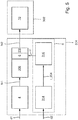
- Figure 3 shows the lighting device 2 in schematic form with a pixel light module 302 and a control unit 304.
- the first image stream fs1 is temporarily stored in an image memory 306.
- An interface unit 308 retrieves an image stream fs1_1, ie an instance of the image stream fs1, from the image memory 306 and, depending on this, transmits an image stream fs1_2 to a further interface unit 310 of the pixel light module 302.
- the interface unit 310 transmits an image stream fs1_3 in an image memory 312 of the pixel light module 302.
- the second calculation unit 6 comprises a third calculation unit 314, which determines information I_204 on the position and movement of the optical axis of the lighting device 2 as a function of the second vehicle data d2.
- the at least one correction value c is determined by means of a fourth calculation unit 316 as a function of the information I_204.
- the at least one correction value c represents a compensation for the information I_204 received about the position and movement of the optical axis.
- the information I_204 includes, for example, a vertical movement of the optical axis by + 1 ° Direction, the correction value c causes a counter-movement for the light distribution by -1 ° in the vertical direction.
- the correction unit 8 is located between a driver unit 318 and the image memory 312 and determines the second image stream fs2 as a function of the at least one correction value c and as a function of the first image stream fs1, here represented by the image stream fs1_3.
- Figure 4 shows an example of the lighting device 2.
- the correction unit 8 is located in the control unit 304 between the image memory 306 and the interface unit 308. Consequently, the second image stream fs2 or instances of the second image stream fs2 are directed to the pixel light arrangement 10.
- Figure 5 shows an example of the lighting device 2.
- the driver unit 318 is arranged on the control unit 304 and transmits the second image stream fs2 directly to the pixel light arrangement 10.
- Figure 6 shows an example of the lighting device 2.
- the calculation unit 316 determines not only the at least one correction value c but also an additional pre-correction value c2.
- the first calculation unit 4 for determining the first image stream fs1 determines the first image stream fs1 as a function of the first vehicle data d1 and the pre-correction value c2.
- the pre-correction value c2 serves to pre-correct the first image stream fs1 in such a way that the calculation unit 316 can take into account low-frequency stabilizations by means of the pre-correction value c2. Higher frequency stabilizations are implemented via the correction value c and the correction unit 8.
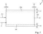
- Figure 7 shows the operation of the correction unit 8 in a schematic form.
- the correction unit 8 receives the first image stream fs1.
- the correction unit 8 determines the selection area sel in relation to the size of the individual images, such as the individual image 702 of the first image stream fs1.
- the selection area sel has a fixed size, for example, which corresponds to a generated image on an image matrix of the pixel light arrangement.
- the correction factor c determines the position of the selection area sel in relation to the respective individual images 702 of the first image stream fs1.
- the position of the selection area sel is selected in the middle as an example in the figure, but can of course differ from it and include, for example, translation and / or rotation of the selection area sel with respect to the individual images or the individual image 702 of the first image stream fs1.
- the correction factor c comprises, for example, values for the translation and / or the rotation of the selection area sel in relation to the single image 702 of the first image stream fs1.
- individual images are cut out from individual images of the first image stream fs1 and provided as individual images of the second image stream fs2.
- the central and non-rotated orientation of the selection area sel shows vertical edge areas v1 and v2, which together are 10-25% larger than a vertical extension of the selection area sel.
- horizontal edge regions h1 and h2 result, which are 2-5% larger than a horizontal extension of the selection region sel.
- the horizontal extension of the individual images of the first and second image stream fs1, fs2 is, for example, larger than the vertical extension.
- the edge areas v1, v2, h1, h2 are also referred to as the dynamic area, which is available for rapid adaptations to stabilize the light distribution.
- the selection area sel for projecting a symbol is, for example, 5 ° of the radiation angle in the horizontal direction and 10 ° of the radiation angle in the vertical direction.
- the first image stream fs1 is always calculated with individual images that are larger than the selection area sel. This allows an asynchronous and fast Compensations of inclination and rolling movement about at least one of the vehicle axles take place by adapting the origin and / or the orientation for determining the selection area sel.
- Figure 8 shows a block diagram in schematic form.
- the schematic block diagram deals with the use of a single-axis MEMS gyroscope 808.
- the scheme explained below also applies, with corresponding adaptations, when using a two-axis MEMS gyroscope and a three-axis MEMS gyroscope which, when used, replace the single axis MEMS gyroscope 808 within the block diagram.
- the single-axis MEMS gyroscope 808 provides an angular velocity signal that describes the angular velocity ⁇ N about a vehicle axis.
- An integrator 810 integrates the angular velocity ⁇ N over time and thus calculates an angle ⁇ N that describes an actual angular position ⁇ N of the vehicle's longitudinal axis relative to the road.
- the angle signals are then filtered by a filter 812, which can be implemented, for example, by a bandpass filter 814. This filters out unwanted signals that could cause the headlamp to be set incorrectly. These undesired signals are in particular high-frequency noise components in the sensor signal and low-frequency components in the sensor signal, which are caused, for example, by an offset error in the gyroscope.
- the filter generates an angular displacement signal ⁇ N.
- the calculation unit 316 determines the correction value c for stabilizing the radiation light distribution as a function of the angular displacement signal ⁇ N.
Landscapes
- Engineering & Computer Science (AREA)
- General Engineering & Computer Science (AREA)
- Mechanical Engineering (AREA)
- Lighting Device Outwards From Vehicle And Optical Signal (AREA)
Abstract
Es wird ein Verfahren zum Betreiben einer Beleuchtungseinrichtung (2) eines Kraftfahrzeugs bereitgestellt, wobei das Verfahren umfasst: Ermitteln eines ersten Bildstroms mit einer Bildrate in Abhängigkeit von ersten Fahrzeugdaten mittels einer ersten Berechnungseinheit (4), Ermitteln wenigstens eines Korrekturwerts mit einer Korrekturrate, welche größer ist als die Bildrate, in Abhängigkeit von zweiten Fahrzeugdaten mittels einer zweiten Berechnungseinheit (6), und Ermitteln eines zweiten Bildstroms in Abhängigkeit von dem ermittelten ersten Bildstrom und in Abhängigkeit von dem wenigstens einen ermittelten Korrekturwert mittels einer Korrektureinheit (8).A method is provided for operating a lighting device (2) of a motor vehicle, the method comprising: determining a first image stream with an image rate as a function of first vehicle data by means of a first calculation unit (4), determining at least one correction value with a correction rate which is greater is than the frame rate, depending on second vehicle data by means of a second calculation unit (6), and determining a second image stream depending on the determined first image stream and depending on the at least one determined correction value by means of a correction unit (8).
Description
Die Erfindung betrifft eine Beleuchtungseinrichtung für ein Kraftfahrzeug sowie ein Verfahren zum Betreiben einer Beleuchtungseinrichtung eines Kraftfahrzeugs.The invention relates to a lighting device for a motor vehicle and a method for operating a lighting device of a motor vehicle.
Seit 1998 schreibt ECE R48 vor, dass eine Veränderung der Fahrzeugneigung um die Nickachse durch eine Veränderung der optischen Achse des Scheinwerfers kompensiert werden muss.Since 1998, ECE R48 has prescribed that a change in the vehicle inclination around the pitch axis must be compensated for by a change in the optical axis of the headlamp.
Darüber hinausgehend erfährt das Fahrzeug Fahrzeugvibrationen sowie weitere Lageveränderungen, womit eine Abstrahllichtverteilung eines Scheinwerfers in Bezug zur Fahrbahn destabilisiert wird.In addition, the vehicle experiences vehicle vibrations as well as further changes in position, with which a light distribution of a headlight is related destabilized to the road surface.
Folglich besteht die Aufgabe der Erfindung darin, eine Beleuchtungseinrichtung dahingehend zu verbessern als dass die Abstrahllichtverteilung stabilisiert wird.Consequently, the object of the invention is to improve an illumination device to the effect that the radiation light distribution is stabilized.
Die der Erfindung zugrunde liegende Aufgabe wird durch eine Beleuchtungseinrichtung für ein Kraftfahrzeug gemäß dem Anspruch 1 und ein Verfahren gemäß einem nebengeordneten Anspruch gelöst. Vorteilhafte Weiterbildungen sind in den Unteransprüchen sowie in der nachfolgenden Beschreibung zu finden.The object underlying the invention is achieved by a lighting device for a motor vehicle according to
Gemäß einem ersten Aspekt dieser Beschreibung wird eine Beleuchtungseinrichtung für ein Kraftfahrzeug beschrieben, wobei die Beleuchtungseinrichtung eine erste Berechnungseinheit, eine zweite Berechnungseinheit und eine Korrektureinheit umfasst. Die Beleuchtungseinrichtung ist so eingerichtet, dass die Beleuchtungseinrichtung einen ersten Bildstrom mit einer Bildrate in Abhängigkeit von ersten Fahrzeugdaten mittels der ersten Berechnungseinheit ermittelt, wenigstens einen Korrekturwert mit einer Korrekturrate, welche größer ist als die Bildrate, in Abhängigkeit von zweiten Fahrzeugdaten mittels der zweiten Berechnungseinheit ermittelt, und einen zweiten Bildstrom in Abhängigkeit von dem ermittelten ersten Bildstrom und in Abhängigkeit von dem wenigstens einen ermittelten Korrekturwert mittels der Korrektureinheit ermittelt.According to a first aspect of this description, a lighting device for a motor vehicle is described, the lighting device comprising a first calculation unit, a second calculation unit and a correction unit. The lighting device is set up in such a way that the lighting device determines a first image stream with an image rate as a function of first vehicle data using the first calculation unit, and at least one correction value with a correction rate which is greater than the image rate as a function of second vehicle data using the second calculation unit , and a second image stream depending on the determined first image stream and depending on the at least one determined correction value determined by means of the correction unit.
Beispielsweise kann auf diese Weise die in das Fahrzeugvorfeld projizierte Abstrahllichtverteilung durch die Berücksichtigung des Korrekturwerts stabilisiert werden. Selbstverständliche profitiert auch jede andere von der Beleuchtungseinrichtung abgestrahlte Lichtverteilung von dieser Art der Stabilisierung. Da der Korrekturwert mit einer höheren Korrekturrate zur Verfügung steht als Einzelbilder des ersten Bildstroms, wird die Aktualisierungsrate der abgestrahlten Lichtverteilung nicht mehr von der Bildrate begrenzt. Durch die erhöhte Korrekturrate treten Latenzen, die beispielsweise bei der Erzeugung und Zwischenpufferung des ersten Bildstroms auftreten, in den Hintergrund. Darüber hinaus entkoppelt die vorgeschlagene Lösung die Erzeugung des ersten Bildstroms von der Stabilisierung der Abstrahllichtverteilung. Vorteilhaft wird die Abstrahllichtverteilung mittels der gegenüber der Bildrate erhöhten Korrekturrate stabilisiert.For example, the radiation light distribution projected into the vehicle apron can be stabilized in this way by taking the correction value into account. Of course, every other light distribution emitted by the lighting device also benefits from this type of stabilization. Since the correction value is available with a higher correction rate than single images of the first image stream, the update rate of the emitted light distribution is no longer limited by the image rate. Due to the increased correction rate, latencies, which occur, for example, when generating and buffering the first image stream, fade into the background. In addition, the proposed solution decouples the generation of the first image stream from the stabilization of the radiation light distribution. The radiation distribution is advantageously stabilized by means of the correction rate, which is higher than the image rate.
Ein vorteilhaftes Beispiel zeichnet sich dadurch aus, dass die Beleuchtungseinrichtung eine Pixellichtanordnung umfasst, wobei die Beleuchtungseinrichtung so eingerichtet ist, dass die Beleuchtungseinrichtung eine Abstrahllichtverteilung in Abhängigkeit von dem zweiten Bildstrom mittels der Pixellichtanordnung von der Beleuchtungseinrichtung abstrahlt.An advantageous example is characterized in that the lighting device comprises a pixel light arrangement, the lighting device being set up in such a way that the lighting device emits a radiation light distribution as a function of the second image stream by means of the pixel light arrangement from the lighting device.
Ein vorteilhaftes Beispiel zeichnet sich dadurch aus, dass die Korrektureinheit einen Auswahlbereich innerhalb jeweiliger Einzelbilder des ersten Bildstromes in Abhängigkeit von dem Korrekturwert selektiert, und die selektierten Auswahlbereiche als jeweilige Einzelbilder des zweiten Bildstroms bereitstellt. Die Abhängigkeit des Auswahlbereichs von dem Korrekturwert ermöglicht die hochfrequente Ermittlung des zweiten Bildstroms. Darüber hinaus wird die Abstrahllichtverteilung in Abhängigkeit von dem Auswahlbereich erzeugt.An advantageous example is characterized in that the correction unit within a selection area selected individual images of the first image stream as a function of the correction value, and provides the selected selection areas as respective individual images of the second image stream. The dependence of the selection area on the correction value enables the high-frequency determination of the second image stream. In addition, the light distribution is generated depending on the selection area.
Ein vorteilhaftes Beispiel zeichnet sich dadurch aus, dass die Einzelbilder des ersten Bildstroms in einer vertikalen Ausdehnung eine erste Differenz zu einer vertikalen Ausdehnung des Auswahlbereichs aufweisen, wobei die Einzelbilder des ersten Bildstroms in einer horizontalen Ausdehnung eine zweite Differenz zu einer horizontalen Ausdehnung des Auswahlbereichs aufweisen, und wobei die erste Differenz größer ist als die zweite Differenz. Hierdurch wird vorteilhaft erreicht, dass ein größerer Bereich in vertikaler Richtung zur Kompensation von typischerweise auftretenden Nickbewegungen des Kraftfahrzeugs zur Verfügung steht.An advantageous example is characterized in that the individual images of the first image stream have a first difference in a vertical extent to a vertical extent of the selection area, the individual images of the first image stream in a horizontal extent have a second difference to a horizontal extent of the selection area, and wherein the first difference is greater than the second difference. This advantageously ensures that a larger area is available in the vertical direction to compensate for pitching movements of the motor vehicle that typically occur.
Ein vorteilhaftes Beispiel zeichnet sich dadurch aus, dass die Einzelbilder des ersten Bildstroms in vertikaler Ausdehnung um 10 bis 25 % größer sind als der Auswahlbereich, und wobei die Bilder des ersten Bildstroms in horizontaler Ausdehnung um 2 bis 5 % größer sind als der Auswahlbereich. Vorteilhaft wird eine speichereffiziente Variante für die Erzeugung und Pufferung des ersten Bildstroms bei möglichst geringer Datenerhöhung des ersten Bildstroms bereitgestellt, die den Anforderungen an die Stabilität der Abstrahllichtverteilung genügt.An advantageous example is characterized in that the individual images of the first image stream in the vertical dimension are 10 to 25% larger than the selection area, and the images of the first image stream in the horizontal dimension are 2 to 5% larger than the selection area. A memory-efficient variant for generating and buffering the first is advantageous Image stream provided with the lowest possible data increase of the first image stream, which meets the requirements for the stability of the radiation light distribution.
Ein vorteilhaftes Beispiel zeichnet sich dadurch aus, dass die Korrektureinheit zwischen einem Bildspeicher für den ersten Bildstrom und einer Treibereinheit der Pixellichtanordnung angeordnet ist. Vorteilhaft wird die Korrektur damit nahe an der Pixellichtanordnung vorgenommen, was die Latenz zwischen Korrektur und Abstrahlung der Abstrahllichtverteilung reduziert.An advantageous example is characterized in that the correction unit is arranged between an image memory for the first image stream and a driver unit of the pixel light arrangement. The correction is thus advantageously carried out close to the pixel light arrangement, which reduces the latency between correction and radiation of the radiation light distribution.
Ein vorteilhaftes Beispiel zeichnet sich dadurch aus, dass die Korrektureinheit zwischen einem Bildspeicher einer Steuereinheit und einer Datenausgangsschnittstelle der Steuereinheit angeordnet ist. Vorteilhaft wird die Korrektur an den Rand der Steuereinheit verlagert, womit die Latenzen innerhalb der Steuereinheit reduziert werden.An advantageous example is characterized in that the correction unit is arranged between an image memory of a control unit and a data output interface of the control unit. The correction is advantageously shifted to the edge of the control unit, thereby reducing the latencies within the control unit.
Ein vorteilhaftes Beispiel zeichnet sich dadurch aus, dass die zweite Berechnungseinheit einen Vorkorrekturwert ermittelt, und wobei die erste Berechnungseinheit den ersten Bildstrom in Abhängigkeit von dem Vorkorrekturwert ermittelt. Vorteilhaft kann der Vorkorrekturwert die Bildstabilität insbesondere bei niederfrequenten Änderungen der Fahrdynamik insoweit verbessern, als dass eine hochfrequente Korrektur mittels des Korrekturwerts die Stabilität der Abstrahllichtverteilung weiter erhöht. Darüber hinaus kann die Grobkorrektur mittels des Vorkorrekturwerts speichereffizient durchgeführt werden, da so die Größe der vorzuhaltenden Einzelbilder des ersten Bildstroms insbesondere die Bildspeichergröße reduziert werden kann.An advantageous example is characterized in that the second calculation unit determines a pre-correction value, and the first calculation unit determines the first image stream as a function of the pre-correction value. The pre-correction value can advantageously improve the image stability, in particular in the case of low-frequency changes in driving dynamics, to the extent that a high-frequency correction by means of the correction value further increases the stability of the radiation light distribution. In addition, the rough correction can be done using the Pre-correction value can be carried out in a memory-efficient manner, since the size of the individual images of the first image stream to be kept can thus be reduced, in particular the size of the image memory.
Ein vorteilhaftes Beispiel zeichnet sich dadurch aus, dass eine Bildauflösung des ersten Bildstroms größer ist als eine Bildauflösung des zweiten Bildstroms. Vorteilhaft wird durch die unterschiedlichen Bildauflösungen die Ermittlung des zweiten Bildstroms vereinfacht. Beispielsweise kann eine Translation des zweiten Bildstromes gegenüber dem ersten Bildstrom durch pixelweises Verschieben auf einfache Art und Weise realisiert werden.An advantageous example is characterized in that an image resolution of the first image stream is greater than an image resolution of the second image stream. The determination of the second image stream is advantageously simplified by the different image resolutions. For example, a translation of the second image stream compared to the first image stream can be implemented in a simple manner by shifting pixel by pixel.
Ein vorteilhaftes Beispiel zeichnet sich dadurch aus, dass die ersten Fahrzeugdaten wenigstens eine der folgenden Größen umfasst: eine Fahrzeuggeschwindigkeit, eine Fahrzeugbeschleunigung, Objektinformationen, Adative Driving Beam-Informationen, einen Lenkradwinkel, eine manuelle Vorgabe der Leuchtweite oder andere Fahrzeuginformationen. In den ersten Fahrzeugdaten sind somit die Informationen enthalten, welche zur Berechnung der Lichtverteilung oder des Bildes oder des Symbols dienen. Die ersten Fahrzeugdaten werden also dazu genutzt, um den Bildstrom zu erzeugen und spielen für die Stabilisierung zum Ende der Verarbeitung hin eine geringere Rolle.An advantageous example is characterized in that the first vehicle data comprises at least one of the following variables: a vehicle speed, vehicle acceleration, object information, additive driving beam information, a steering wheel angle, manual specification of the headlight range or other vehicle information. The first vehicle data thus contains the information which is used to calculate the light distribution or the image or the symbol. The first vehicle data are therefore used to generate the image stream and play a minor role in stabilization towards the end of processing.
Ein vorteilhaftes Beispiel zeichnet sich dadurch aus, dass die zweiten Fahrzeugdaten wenigstens eine der folgenden Größen umfasst: eine Winkelgeschwindigkeit, welche mittels eines Gyroskops oder mittels einer inertialen Messeinheit ermittelt wird, oder einen Winkel, welcher mittels des Gyrosops, der inertialen Messeinheit oder mittels Achssensoren ermittelt wird.An advantageous example is characterized in that the second vehicle data comprises at least one of the following variables: an angular velocity, which is determined by means of a gyroscope or by means of an inertial measuring unit, or an angle, which is determined by means of the gyroscope, the inertial measuring unit or by means of axis sensors.
Ein zweiter Aspekt dieser Beschreibung betrifft ein Verfahren zum Betreiben einer Beleuchtungseinrichtung eines Kraftfahrzeugs, wobei das Verfahren umfasst: Ermitteln eines ersten Bildstroms mit einer Bildrate in Abhängigkeit von ersten Fahrzeugdaten mittels einer ersten Berechnungseinheit, Ermitteln wenigstens eines Korrekturwerts mit einer Korrekturrate, welche größer ist als die Bildrate, in Abhängigkeit von zweiten Fahrzeugdaten mittels einer zweiten Berechnungseinheit, Ermitteln eines zweiten Bildstroms in Abhängigkeit von dem ermittelten ersten Bildstrom und in Abhängigkeit von dem wenigstens einen ermittelten Korrekturwert mittels einer Korrektureinheit, und Abstrahlen einer Abstrahllichtverteilung in Abhängigkeit von dem zweiten Bildstrom mittels einer Pixellichtanordnung von der Beleuchtungseinrichtung.A second aspect of this description relates to a method for operating a lighting device of a motor vehicle, the method comprising: determining a first image current with an image rate as a function of first vehicle data by means of a first calculation unit, determining at least one correction value with a correction rate which is greater than that Frame rate, as a function of second vehicle data by means of a second calculation unit, determining a second image flow as a function of the determined first image stream and as a function of the at least one determined correction value by means of a correction unit, and emitting a radiation light distribution as a function of the second image stream by means of a pixel light arrangement of the lighting device.
In der Zeichnung zeigen:
-
Figur 1 -
Figur 2 -
Figuren 3-5
jeweils ein Beispiel für ein Pixellichtmodul und eine Steuereinheit; -
Figur 7
eine Arbeitsweise einer Korrektureinheit in schematischer Form; und -
Figur 8
ein schematisches Blockdiagramm zur Ermittlung eines Korrekturwerts.
-
Figure 1 a lighting device in schematic form; -
Figure 2 a motor vehicle in schematic form; -
Figures 3-5
each an example of a pixel light module and a control unit; -
Figure 7
an operation of a correction unit in schematic form; and -
Figure 8
a schematic block diagram for determining a correction value.
Der Korrekturwert c wird mit einer Frequenz größer 1 Hz ermittelt, um die Verarbeitungszeiten für die Erzeugung und den Transport des ersten Bildstroms fs1 zu kompensieren. Diese Verarbeitungszeit des ersten Bildstroms ist beispielsweise größer als 30 ms.The correction value c is determined with a frequency greater than 1 Hz in order to compensate for the processing times for the generation and the transport of the first image stream fs1. This processing time of the first image stream is, for example, greater than 30 ms.
Die Pixellichtanordnung 10 umfasst wenigstens eine nicht dargestellte Lichtquelle sowie eine nicht dargestellte Projektionsanordnung oder eine nicht dargestellte Reflexionsanordnung. Beispielsweise umfasst die Pixellichtanordnung 10 ein Mikrospiegelarray (Digital Micromirror Device: DMD), ein Liquid Crystal Display (LCD), eine Liquid-Crystal-on-Silicon (kurz LCoS)-Matrixanzeige, eine LED-Matrix usw. Grundsätzlich sind auch Laserscanner zur Realisierung der Pixellichtanordnung 10 geeignet. Folglich kann jede Lichtanordnung als Pixellichtanordnung 10 verwendet werden, welche ein hochaufgelöstes Bild in das Vorfeld des Kraftfahrzeugs projiziert.The
Die ersten Fahrzeugdaten d1 umfassen beispielsweise eine Basiswinkeleinstellung des Scheinwerfers, welche genutzt wird, um die Ausrichtung einer optischen Achse der Beleuchtungseinrichtung 2 zu berechnen. Die Basiswinkeleinstellung ist eine optionale der ersten Berechnungseinheit 4 zuzuführende Größe. Sie stellt dabei einen Basiswinkel dar, welcher von einem anderen System zur Einstellung einer Sollwinkellage der optischen Achse der Beleuchtungseinrichtung 2 stammt, oder der sich in anderen Signalen abbildet. Beispielhaft sei eine manuelle Einstellung der Sollwinkellage der optischen Achse zur Kompensation von Beladungseinflüssen genannt. Des Weiteren können auch eine Fahrzeuggeschwindigkeit, eine Fahrzeugbeschleunigung oder andere Größen Teil der ersten Fahrzeugdaten d1 sein.The first vehicle data d1 include, for example Base angle setting of the headlight, which is used to calculate the alignment of an optical axis of the
Der erste Bildstrom fs1 wird mit einer Bildrate, welche auch als Bildupdaterate bezeichenbar ist, von der ersten Berechnungseinheit 4 bereitgestellt. Der Korrekturwert c wird mit einer Korrekturrate, welche auch als Korrekturupdaterate bezeichenbar ist, von der zweiten Berechnungseinheit 6 bereitgestellt.The first image stream fs1 is provided by the
Die zweite Berechnungseinheit 6 umfasst eine dritte Berechnungseinheit 314, welche in Abhängigkeit von den zweiten Fahrzeugdaten d2 eine Information I_204 über Lage und Bewegung der optischen Achse der Beleuchtungseinrichtung 2 ermittelt. Der wenigstens eine Korrekturwert c wird mittels einer vierten Berechnungseinheit 316 in Abhängigkeit von der Information I_204 ermittelt. Dabei stellt der wenigstens eine Korrekturwert c eine Kompensation für die erhaltene Information I_204 über die Lage und Bewegung der optischen Achse dar. Umfasst die Information I_204 beispielsweise eine Bewegung der optischen Achse um +1° in vertikaler Richtung so bewirkt der Korrekturwert c eine Gegenbewegung für die Abstrahllichtverteilung um -1° in vertikaler Richtung.The
Die Korrektureinheit 8 befindet sich zwischen einer Treibereinheit 318 und dem Bildspeicher 312 und ermittelt den zweiten Bildstrom fs2 in Abhängigkeit von dem wenigstens einen Korrekturwert c und in Abhängigkeit von dem ersten Bildstrom fs1, hier repräsentiert durch den Bildstrom fs1_3.The
In vertikaler Richtung in Bezug zu der Fahrbahn des Kraftfahrzeugs ergeben sich bei der beispielhaft gezeigten mittigen und nicht verdrehten Ausrichtung des Auswahlbereichs sel vertikale Randbereiche v1 und v2, welche gemeinsam um 10-25 % größer sind als eine vertikale Ausdehnung des Auswahlbereichs sel. In horizontaler Richtung ergeben sich horizontale Randbereiche h1 und h2, welcher um 2-5 % größer sind als eine horizontale Ausdehnung des Auswahlbereichs sel. Die horizontale Ausdehnung der Einzelbilder des ersten und zweiten Bildstroms fs1, fs2 ist beispielhaft größer als die vertikale Ausdehnung. Die Randbereiche v1, v2, h1, h2 werden auch als dynamischer Bereich bezeichnet, der für schnelle Adaptionen zur Stabilisierung der Abstrahllichtverteilung zur Verfügung steht.In the vertical direction in relation to the roadway of the motor vehicle, the central and non-rotated orientation of the selection area sel shows vertical edge areas v1 and v2, which together are 10-25% larger than a vertical extension of the selection area sel. In the horizontal direction horizontal edge regions h1 and h2 result, which are 2-5% larger than a horizontal extension of the selection region sel. The horizontal extension of the individual images of the first and second image stream fs1, fs2 is, for example, larger than the vertical extension. The edge areas v1, v2, h1, h2 are also referred to as the dynamic area, which is available for rapid adaptations to stabilize the light distribution.
Der Auswahlbereich sel zur Projektion eines Symbols ist beispielsweise 5° des Abstrahlwinkels in horizontaler Richtung und 10° des Abstrahlwinkels in vertikaler Richtung.The selection area sel for projecting a symbol is, for example, 5 ° of the radiation angle in the horizontal direction and 10 ° of the radiation angle in the vertical direction.
Vorteilhaft wird der erste Bildstrom fs1 stets mit Einzelbildern berechnet, welche größer sind als der Auswahlbereich sel. So kann eine asynchrone und schnelle Kompensationen von Neigung und Rollbewegung um wenigstens eine der Fahrzeugachsen erfolgen, indem der Ursprung und/oder die Orientierung zur Ermittlung des Auswahlbereichs sel angepasst wird.Advantageously, the first image stream fs1 is always calculated with individual images that are larger than the selection area sel. This allows an asynchronous and fast Compensations of inclination and rolling movement about at least one of the vehicle axles take place by adapting the origin and / or the orientation for determining the selection area sel.
Das Ein-Achsen-MEMS-Gyroskop 808 stellt ein Winkelgeschwindigkeitssignal bereit, dass die Winkelgeschwindigkeit ωN um eine Fahrzeugachse beschreibt. Ein Integrator 810 führt eine Integration der Winkelgeschwindigkeit ωN über der Zeit durch und berechnet damit einen Winkel θN, der eine Istwinkellage θN der Fahrzeuglängsachse relativ zur Fahrbahn beschreibt. Anschließend erfolgt eine Filterung der Winkelsignale durch einen Filter 812, der beispielhaft durch einen Bandpass 814 realisiert werden kann. Hierbei werden unerwünschte Signale herausgefiltert, welche für eine falsche Einstellung des Scheinwerfers sorgen könnten. Diese unerwünschten Signale sind insbesondere hochfrequente Rauschanteile im Sensorsignal und niederfrequente Anteile im Sensorsignal, welche zum Beispiel durch einen Offsetfehler im Gyroskop verursacht werden. Der Filter erzeugt ein Winkelverschiebungssignal ΔθN. Die Berechnungseinheit 316 ermittelt in Abhängigkeit von dem Winkelverschiebungssignal ΔθN den Korrekturwert c zur Stabilisierung der Abstrahllichtverteilung.The single-
Claims (13)
einen ersten Bildstrom mit einer Bildrate in Abhängigkeit von ersten Fahrzeugdaten mittels der ersten Berechnungseinheit (4) ermittelt,
wenigstens einen Korrekturwert mit einer Korrekturrate, welche größer ist als die Bildrate, in Abhängigkeit von zweiten Fahrzeugdaten mittels der zweiten Berechnungseinheit (6) ermittelt, und
einen zweiten Bildstrom in Abhängigkeit von dem ermittelten ersten Bildstrom und in Abhängigkeit von dem wenigstens einen ermittelten Korrekturwert mittels der Korrektureinheit (8) ermittelt.A lighting device (2) for a motor vehicle, the lighting device (2) comprising a first calculation unit (4), a second calculation unit (6) and a correction unit (8), the lighting device (2) being set up in such a way that the lighting device ( 2)
determines a first image stream with an image rate as a function of first vehicle data using the first calculation unit (4),
at least one correction value with a correction rate, which is greater than the frame rate, determined as a function of second vehicle data by means of the second calculation unit (6), and
a second image stream as a function of the determined first image stream and as a function of the at least one determined correction value by means of the correction unit (8) determined.
eine Abstrahllichtverteilung in Abhängigkeit von dem zweiten Bildstrom mittels der Pixellichtanordnung (10) von der Beleuchtungseinrichtung abstrahlt.The lighting device (2) according to claim 1, wherein the lighting device (2) comprises a pixel light arrangement (10), and wherein the lighting device (2) is set up in such a way that the lighting device (2)
emits a light distribution as a function of the second image stream from the lighting device by means of the pixel light arrangement (10).
einen Auswahlbereich innerhalb jeweiliger Einzelbilder des ersten Bildstromes in Abhängigkeit von dem Korrekturwert selektiert, und
die selektierten Auswahlbereiche als jeweilige Einzelbilder des zweiten Bildstroms bereitstellt.The lighting device (2) according to claim 1 or 2, wherein the correction unit (8)
selects a selection area within respective individual images of the first image stream as a function of the correction value, and
provides the selected selection areas as respective individual images of the second image stream.
Applications Claiming Priority (1)
| Application Number | Priority Date | Filing Date | Title |
|---|---|---|---|
| DE102019102327.0A DE102019102327A1 (en) | 2019-01-30 | 2019-01-30 | Lighting device for a motor vehicle and method |
Publications (2)
| Publication Number | Publication Date |
|---|---|
| EP3689679A1 true EP3689679A1 (en) | 2020-08-05 |
| EP3689679B1 EP3689679B1 (en) | 2021-10-13 |
Family
ID=69190658
Family Applications (1)
| Application Number | Title | Priority Date | Filing Date |
|---|---|---|---|
| EP20153333.8A Active EP3689679B1 (en) | 2019-01-30 | 2020-01-23 | Method and lighting device for a motor vehicle |
Country Status (2)
| Country | Link |
|---|---|
| EP (1) | EP3689679B1 (en) |
| DE (1) | DE102019102327A1 (en) |
Citations (7)
| Publication number | Priority date | Publication date | Assignee | Title |
|---|---|---|---|---|
| EP1433655A2 (en) * | 2002-12-27 | 2004-06-30 | Ichikoh Industries, Ltd. | Digital lighting apparatus for vehicle, controller for digital lighting apparatus, and control program for digital lighting apparatus |
| DE102011109434A1 (en) * | 2011-08-04 | 2012-06-06 | Daimler Ag | Method for maintaining constant light emission direction of headlight of vehicle during movement of vehicle body, involves comparing actual value of module with reference value of pattern, and determining actuating signal for control |
| DE102013019021A1 (en) * | 2013-11-13 | 2015-05-13 | Audi Ag | Method for driver assistance and motor vehicle |
| WO2016021154A1 (en) * | 2014-08-06 | 2016-02-11 | パナソニックIpマネジメント株式会社 | Lighting device, and automobile in which same is mounted |
| DE102016122066A1 (en) * | 2016-11-16 | 2018-05-17 | Automotive Lighting Reutlingen Gmbh | Method for adjusting the angular position of the optical axis of a headlight of a motor vehicle and lighting device of the motor vehicle |
| DE102017005019A1 (en) * | 2017-05-26 | 2018-11-29 | Daimler Ag | Lighting device and method for its operation |
| WO2019006481A1 (en) * | 2017-07-03 | 2019-01-10 | Zkw Group Gmbh | Method for generating a variable high beam light distribution and device |
Family Cites Families (4)
| Publication number | Priority date | Publication date | Assignee | Title |
|---|---|---|---|---|
| JP3128606B2 (en) * | 1995-12-28 | 2001-01-29 | 株式会社小糸製作所 | Illumination direction control device for vehicle lighting |
| FR2908361B1 (en) * | 2006-11-10 | 2009-01-02 | Valeo Vision Sa | SYSTEM FOR THE DYNAMIC CORRECTION OF THE ORIENTATION OF A LIGHT SOURCE OF A VEHICLE AND ASSOCIATED METHOD |
| DE102012007908B4 (en) * | 2012-04-23 | 2014-10-16 | Audi Ag | Method and headlight system to compensate for alignment errors of a headlight |
| WO2017180882A1 (en) * | 2016-04-14 | 2017-10-19 | Gentex Corporation | Camera based headlight control system |
-
2019
- 2019-01-30 DE DE102019102327.0A patent/DE102019102327A1/en active Pending
-
2020
- 2020-01-23 EP EP20153333.8A patent/EP3689679B1/en active Active
Patent Citations (7)
| Publication number | Priority date | Publication date | Assignee | Title |
|---|---|---|---|---|
| EP1433655A2 (en) * | 2002-12-27 | 2004-06-30 | Ichikoh Industries, Ltd. | Digital lighting apparatus for vehicle, controller for digital lighting apparatus, and control program for digital lighting apparatus |
| DE102011109434A1 (en) * | 2011-08-04 | 2012-06-06 | Daimler Ag | Method for maintaining constant light emission direction of headlight of vehicle during movement of vehicle body, involves comparing actual value of module with reference value of pattern, and determining actuating signal for control |
| DE102013019021A1 (en) * | 2013-11-13 | 2015-05-13 | Audi Ag | Method for driver assistance and motor vehicle |
| WO2016021154A1 (en) * | 2014-08-06 | 2016-02-11 | パナソニックIpマネジメント株式会社 | Lighting device, and automobile in which same is mounted |
| DE102016122066A1 (en) * | 2016-11-16 | 2018-05-17 | Automotive Lighting Reutlingen Gmbh | Method for adjusting the angular position of the optical axis of a headlight of a motor vehicle and lighting device of the motor vehicle |
| DE102017005019A1 (en) * | 2017-05-26 | 2018-11-29 | Daimler Ag | Lighting device and method for its operation |
| WO2019006481A1 (en) * | 2017-07-03 | 2019-01-10 | Zkw Group Gmbh | Method for generating a variable high beam light distribution and device |
Also Published As
| Publication number | Publication date |
|---|---|
| EP3689679B1 (en) | 2021-10-13 |
| DE102019102327A1 (en) | 2020-07-30 |
Similar Documents
| Publication | Publication Date | Title |
|---|---|---|
| DE112018001655B4 (en) | Display device and moving body with the display device | |
| EP3620842B1 (en) | Concept for adjusting a head-up display in a motor vehicle | |
| EP3541659B1 (en) | Method for adjusting the angular position of the optical axis of a headlamp of a motor vehicle, and illumination device of the motor vehicle | |
| DE102018129741A1 (en) | Device and method for controlling a display of a vehicle | |
| DE2753321A1 (en) | IMAGING DEVICE | |
| DE102008025458A1 (en) | Method and device for calibrating a horizontal cut-off line created by a headlight of a vehicle | |
| DE102013208971A1 (en) | Apparatus and method for projecting image information into a field of view of a vehicle occupant of a vehicle | |
| DE10059315A1 (en) | Arrangement and method for monitoring the surroundings of a vehicle | |
| EP1897057A1 (en) | Method for a distortion-free display | |
| WO2019233687A1 (en) | Concept for providing correction values for displaying augmented reality content on a head-up display for a motor vehicle | |
| DE19704427A1 (en) | Device for adjusting beam spread of automobiles headlamps | |
| EP2130718B1 (en) | Method and device for controlling the light emission of at least one front headlamp of a vehicle | |
| DE102005001429A1 (en) | Method for image-position correction of a monitor image | |
| DE102008025459A1 (en) | Method and device for calibrating a vertical light-dark boundary generated by a headlight of a vehicle | |
| DE102016213028A1 (en) | Motor vehicle with one or more headlamps | |
| EP2131598A2 (en) | Stereo camera system and method of determining at least one calibration error in a stereo camera system | |
| WO2020249367A1 (en) | Control of a display of an augmented reality head-up display apparatus for a motor vehicle | |
| DE102014206569A1 (en) | A method and apparatus for controlling a light output of an imager of a visual field display device for displaying a stereoscopic image and visual field display device | |
| DE112016001666T5 (en) | DISPLAY DEVICE | |
| DE112019004159T5 (en) | VIBRATION COMPENSATION DEVICE AND VIBRATION COMPENSATION METHOD | |
| EP3689679B1 (en) | Method and lighting device for a motor vehicle | |
| WO2010034743A1 (en) | Image projection through grid scanning of a modulated light beam using mirrors | |
| DE102016005452A1 (en) | A method of correcting a position of an augmented reality object projected on a display of a vehicle due to an obstructed landing gear of the vehicle | |
| DE102015116160B4 (en) | Head-up display with situation-based adjustment of the display of virtual image content | |
| DE102019204057A1 (en) | Provision of correction values for the projection of a light mark |
Legal Events
| Date | Code | Title | Description |
|---|---|---|---|
| PUAI | Public reference made under article 153(3) epc to a published international application that has entered the european phase |
Free format text: ORIGINAL CODE: 0009012 |
|
| STAA | Information on the status of an ep patent application or granted ep patent |
Free format text: STATUS: THE APPLICATION HAS BEEN PUBLISHED |
|
| AK | Designated contracting states |
Kind code of ref document: A1 Designated state(s): AL AT BE BG CH CY CZ DE DK EE ES FI FR GB GR HR HU IE IS IT LI LT LU LV MC MK MT NL NO PL PT RO RS SE SI SK SM TR |
|
| AX | Request for extension of the european patent |
Extension state: BA ME |
|
| STAA | Information on the status of an ep patent application or granted ep patent |
Free format text: STATUS: REQUEST FOR EXAMINATION WAS MADE |
|
| 17P | Request for examination filed |
Effective date: 20201215 |
|
| RBV | Designated contracting states (corrected) |
Designated state(s): AL AT BE BG CH CY CZ DE DK EE ES FI FR GB GR HR HU IE IS IT LI LT LU LV MC MK MT NL NO PL PT RO RS SE SI SK SM TR |
|
| REG | Reference to a national code |
Ref country code: DE Ref legal event code: R079 Ref document number: 502020000253 Country of ref document: DE Free format text: PREVIOUS MAIN CLASS: B60Q0001115000 Ipc: F21S0041600000 |
|
| GRAP | Despatch of communication of intention to grant a patent |
Free format text: ORIGINAL CODE: EPIDOSNIGR1 |
|
| STAA | Information on the status of an ep patent application or granted ep patent |
Free format text: STATUS: GRANT OF PATENT IS INTENDED |
|
| RIC1 | Information provided on ipc code assigned before grant |
Ipc: F21S 41/60 20180101AFI20210414BHEP |
|
| INTG | Intention to grant announced |
Effective date: 20210512 |
|
| GRAS | Grant fee paid |
Free format text: ORIGINAL CODE: EPIDOSNIGR3 |
|
| GRAA | (expected) grant |
Free format text: ORIGINAL CODE: 0009210 |
|
| STAA | Information on the status of an ep patent application or granted ep patent |
Free format text: STATUS: THE PATENT HAS BEEN GRANTED |
|
| AK | Designated contracting states |
Kind code of ref document: B1 Designated state(s): AL AT BE BG CH CY CZ DE DK EE ES FI FR GB GR HR HU IE IS IT LI LT LU LV MC MK MT NL NO PL PT RO RS SE SI SK SM TR |
|
| REG | Reference to a national code |
Ref country code: GB Ref legal event code: FG4D Free format text: NOT ENGLISH |
|
| REG | Reference to a national code |
Ref country code: CH Ref legal event code: EP |
|
| REG | Reference to a national code |
Ref country code: DE Ref legal event code: R096 Ref document number: 502020000253 Country of ref document: DE |
|
| REG | Reference to a national code |
Ref country code: IE Ref legal event code: FG4D Free format text: LANGUAGE OF EP DOCUMENT: GERMAN |
|
| REG | Reference to a national code |
Ref country code: AT Ref legal event code: REF Ref document number: 1438440 Country of ref document: AT Kind code of ref document: T Effective date: 20211115 |
|
| REG | Reference to a national code |
Ref country code: LT Ref legal event code: MG9D |
|
| REG | Reference to a national code |
Ref country code: NL Ref legal event code: MP Effective date: 20211013 |
|
| PG25 | Lapsed in a contracting state [announced via postgrant information from national office to epo] |
Ref country code: RS Free format text: LAPSE BECAUSE OF FAILURE TO SUBMIT A TRANSLATION OF THE DESCRIPTION OR TO PAY THE FEE WITHIN THE PRESCRIBED TIME-LIMIT Effective date: 20211013 Ref country code: LT Free format text: LAPSE BECAUSE OF FAILURE TO SUBMIT A TRANSLATION OF THE DESCRIPTION OR TO PAY THE FEE WITHIN THE PRESCRIBED TIME-LIMIT Effective date: 20211013 Ref country code: FI Free format text: LAPSE BECAUSE OF FAILURE TO SUBMIT A TRANSLATION OF THE DESCRIPTION OR TO PAY THE FEE WITHIN THE PRESCRIBED TIME-LIMIT Effective date: 20211013 Ref country code: BG Free format text: LAPSE BECAUSE OF FAILURE TO SUBMIT A TRANSLATION OF THE DESCRIPTION OR TO PAY THE FEE WITHIN THE PRESCRIBED TIME-LIMIT Effective date: 20220113 |
|
| PG25 | Lapsed in a contracting state [announced via postgrant information from national office to epo] |
Ref country code: IS Free format text: LAPSE BECAUSE OF FAILURE TO SUBMIT A TRANSLATION OF THE DESCRIPTION OR TO PAY THE FEE WITHIN THE PRESCRIBED TIME-LIMIT Effective date: 20220213 Ref country code: SE Free format text: LAPSE BECAUSE OF FAILURE TO SUBMIT A TRANSLATION OF THE DESCRIPTION OR TO PAY THE FEE WITHIN THE PRESCRIBED TIME-LIMIT Effective date: 20211013 Ref country code: PT Free format text: LAPSE BECAUSE OF FAILURE TO SUBMIT A TRANSLATION OF THE DESCRIPTION OR TO PAY THE FEE WITHIN THE PRESCRIBED TIME-LIMIT Effective date: 20220214 Ref country code: PL Free format text: LAPSE BECAUSE OF FAILURE TO SUBMIT A TRANSLATION OF THE DESCRIPTION OR TO PAY THE FEE WITHIN THE PRESCRIBED TIME-LIMIT Effective date: 20211013 Ref country code: NO Free format text: LAPSE BECAUSE OF FAILURE TO SUBMIT A TRANSLATION OF THE DESCRIPTION OR TO PAY THE FEE WITHIN THE PRESCRIBED TIME-LIMIT Effective date: 20220113 Ref country code: NL Free format text: LAPSE BECAUSE OF FAILURE TO SUBMIT A TRANSLATION OF THE DESCRIPTION OR TO PAY THE FEE WITHIN THE PRESCRIBED TIME-LIMIT Effective date: 20211013 Ref country code: LV Free format text: LAPSE BECAUSE OF FAILURE TO SUBMIT A TRANSLATION OF THE DESCRIPTION OR TO PAY THE FEE WITHIN THE PRESCRIBED TIME-LIMIT Effective date: 20211013 Ref country code: HR Free format text: LAPSE BECAUSE OF FAILURE TO SUBMIT A TRANSLATION OF THE DESCRIPTION OR TO PAY THE FEE WITHIN THE PRESCRIBED TIME-LIMIT Effective date: 20211013 Ref country code: GR Free format text: LAPSE BECAUSE OF FAILURE TO SUBMIT A TRANSLATION OF THE DESCRIPTION OR TO PAY THE FEE WITHIN THE PRESCRIBED TIME-LIMIT Effective date: 20220114 Ref country code: ES Free format text: LAPSE BECAUSE OF FAILURE TO SUBMIT A TRANSLATION OF THE DESCRIPTION OR TO PAY THE FEE WITHIN THE PRESCRIBED TIME-LIMIT Effective date: 20211013 |
|
| REG | Reference to a national code |
Ref country code: DE Ref legal event code: R097 Ref document number: 502020000253 Country of ref document: DE |
|
| PG25 | Lapsed in a contracting state [announced via postgrant information from national office to epo] |
Ref country code: SM Free format text: LAPSE BECAUSE OF FAILURE TO SUBMIT A TRANSLATION OF THE DESCRIPTION OR TO PAY THE FEE WITHIN THE PRESCRIBED TIME-LIMIT Effective date: 20211013 Ref country code: SK Free format text: LAPSE BECAUSE OF FAILURE TO SUBMIT A TRANSLATION OF THE DESCRIPTION OR TO PAY THE FEE WITHIN THE PRESCRIBED TIME-LIMIT Effective date: 20211013 Ref country code: RO Free format text: LAPSE BECAUSE OF FAILURE TO SUBMIT A TRANSLATION OF THE DESCRIPTION OR TO PAY THE FEE WITHIN THE PRESCRIBED TIME-LIMIT Effective date: 20211013 Ref country code: EE Free format text: LAPSE BECAUSE OF FAILURE TO SUBMIT A TRANSLATION OF THE DESCRIPTION OR TO PAY THE FEE WITHIN THE PRESCRIBED TIME-LIMIT Effective date: 20211013 Ref country code: DK Free format text: LAPSE BECAUSE OF FAILURE TO SUBMIT A TRANSLATION OF THE DESCRIPTION OR TO PAY THE FEE WITHIN THE PRESCRIBED TIME-LIMIT Effective date: 20211013 Ref country code: CZ Free format text: LAPSE BECAUSE OF FAILURE TO SUBMIT A TRANSLATION OF THE DESCRIPTION OR TO PAY THE FEE WITHIN THE PRESCRIBED TIME-LIMIT Effective date: 20211013 |
|
| PLBE | No opposition filed within time limit |
Free format text: ORIGINAL CODE: 0009261 |
|
| STAA | Information on the status of an ep patent application or granted ep patent |
Free format text: STATUS: NO OPPOSITION FILED WITHIN TIME LIMIT |
|
| PG25 | Lapsed in a contracting state [announced via postgrant information from national office to epo] |
Ref country code: MC Free format text: LAPSE BECAUSE OF FAILURE TO SUBMIT A TRANSLATION OF THE DESCRIPTION OR TO PAY THE FEE WITHIN THE PRESCRIBED TIME-LIMIT Effective date: 20211013 |
|
| 26N | No opposition filed |
Effective date: 20220714 |
|
| REG | Reference to a national code |
Ref country code: BE Ref legal event code: MM Effective date: 20220131 |
|
| PG25 | Lapsed in a contracting state [announced via postgrant information from national office to epo] |
Ref country code: LU Free format text: LAPSE BECAUSE OF NON-PAYMENT OF DUE FEES Effective date: 20220123 Ref country code: AL Free format text: LAPSE BECAUSE OF FAILURE TO SUBMIT A TRANSLATION OF THE DESCRIPTION OR TO PAY THE FEE WITHIN THE PRESCRIBED TIME-LIMIT Effective date: 20211013 |
|
| PG25 | Lapsed in a contracting state [announced via postgrant information from national office to epo] |
Ref country code: SI Free format text: LAPSE BECAUSE OF FAILURE TO SUBMIT A TRANSLATION OF THE DESCRIPTION OR TO PAY THE FEE WITHIN THE PRESCRIBED TIME-LIMIT Effective date: 20211013 Ref country code: BE Free format text: LAPSE BECAUSE OF NON-PAYMENT OF DUE FEES Effective date: 20220131 |
|
| PG25 | Lapsed in a contracting state [announced via postgrant information from national office to epo] |
Ref country code: IE Free format text: LAPSE BECAUSE OF NON-PAYMENT OF DUE FEES Effective date: 20220123 |
|
| PG25 | Lapsed in a contracting state [announced via postgrant information from national office to epo] |
Ref country code: IT Free format text: LAPSE BECAUSE OF FAILURE TO SUBMIT A TRANSLATION OF THE DESCRIPTION OR TO PAY THE FEE WITHIN THE PRESCRIBED TIME-LIMIT Effective date: 20211013 |
|
| P01 | Opt-out of the competence of the unified patent court (upc) registered |
Effective date: 20230508 |
|
| REG | Reference to a national code |
Ref country code: CH Ref legal event code: PL |
|
| PG25 | Lapsed in a contracting state [announced via postgrant information from national office to epo] |
Ref country code: LI Free format text: LAPSE BECAUSE OF NON-PAYMENT OF DUE FEES Effective date: 20230131 Ref country code: CH Free format text: LAPSE BECAUSE OF NON-PAYMENT OF DUE FEES Effective date: 20230131 |
|
| PGFP | Annual fee paid to national office [announced via postgrant information from national office to epo] |
Ref country code: FR Payment date: 20231219 Year of fee payment: 5 |
|
| PG25 | Lapsed in a contracting state [announced via postgrant information from national office to epo] |
Ref country code: MK Free format text: LAPSE BECAUSE OF FAILURE TO SUBMIT A TRANSLATION OF THE DESCRIPTION OR TO PAY THE FEE WITHIN THE PRESCRIBED TIME-LIMIT Effective date: 20211013 Ref country code: CY Free format text: LAPSE BECAUSE OF FAILURE TO SUBMIT A TRANSLATION OF THE DESCRIPTION OR TO PAY THE FEE WITHIN THE PRESCRIBED TIME-LIMIT Effective date: 20211013 |
|
| PGFP | Annual fee paid to national office [announced via postgrant information from national office to epo] |
Ref country code: DE Payment date: 20231219 Year of fee payment: 5 |
|
| PG25 | Lapsed in a contracting state [announced via postgrant information from national office to epo] |
Ref country code: HU Free format text: LAPSE BECAUSE OF FAILURE TO SUBMIT A TRANSLATION OF THE DESCRIPTION OR TO PAY THE FEE WITHIN THE PRESCRIBED TIME-LIMIT; INVALID AB INITIO Effective date: 20200123 |
|
| GBPC | Gb: european patent ceased through non-payment of renewal fee |
Effective date: 20240123 |
|
| PG25 | Lapsed in a contracting state [announced via postgrant information from national office to epo] |
Ref country code: MT Free format text: LAPSE BECAUSE OF FAILURE TO SUBMIT A TRANSLATION OF THE DESCRIPTION OR TO PAY THE FEE WITHIN THE PRESCRIBED TIME-LIMIT Effective date: 20211013 |