EP3689583B1 - Vorrichtung zur befestigung einer druckplattform zur verwendung mit einem 3d-drucker - Google Patents
Vorrichtung zur befestigung einer druckplattform zur verwendung mit einem 3d-drucker Download PDFInfo
- Publication number
- EP3689583B1 EP3689583B1 EP19154650.6A EP19154650A EP3689583B1 EP 3689583 B1 EP3689583 B1 EP 3689583B1 EP 19154650 A EP19154650 A EP 19154650A EP 3689583 B1 EP3689583 B1 EP 3689583B1
- Authority
- EP
- European Patent Office
- Prior art keywords
- printing platform
- clamp
- printer
- extrusion
- carriage
- Prior art date
- Legal status (The legal status is an assumption and is not a legal conclusion. Google has not performed a legal analysis and makes no representation as to the accuracy of the status listed.)
- Active
Links
Images



Classifications
-
- B—PERFORMING OPERATIONS; TRANSPORTING
- B29—WORKING OF PLASTICS; WORKING OF SUBSTANCES IN A PLASTIC STATE IN GENERAL
- B29C—SHAPING OR JOINING OF PLASTICS; SHAPING OF MATERIAL IN A PLASTIC STATE, NOT OTHERWISE PROVIDED FOR; AFTER-TREATMENT OF THE SHAPED PRODUCTS, e.g. REPAIRING
- B29C64/00—Additive manufacturing, i.e. manufacturing of three-dimensional [3D] objects by additive deposition, additive agglomeration or additive layering, e.g. by 3D printing, stereolithography or selective laser sintering
- B29C64/20—Apparatus for additive manufacturing; Details thereof or accessories therefor
- B29C64/245—Platforms or substrates
-
- B—PERFORMING OPERATIONS; TRANSPORTING
- B33—ADDITIVE MANUFACTURING TECHNOLOGY
- B33Y—ADDITIVE MANUFACTURING, i.e. MANUFACTURING OF THREE-DIMENSIONAL [3D] OBJECTS BY ADDITIVE DEPOSITION, ADDITIVE AGGLOMERATION OR ADDITIVE LAYERING, e.g. BY 3D PRINTING, STEREOLITHOGRAPHY OR SELECTIVE LASER SINTERING
- B33Y30/00—Apparatus for additive manufacturing; Details thereof or accessories therefor
Definitions
- the present invention relates to an extrusion-type 3D-printer comprising a printing platform fixture apparatus. Further, the present invention relates to use of the extrusion-type 3D-printer.
- Certain embodiments in this disclosure provide a solution for bed attachment and alignment in 3D printing applications, in particular in the field of extrusion-based technologies such as Fused Deposition Modelling (FDM) and Fused Filament Fabrication (FFF). More specifically, the present disclosure provides a printing platform fixture apparatus for use with a 3D-printer.
- FDM Fused Deposition Modelling
- FFF Fused Filament Fabrication
- Additive manufacturing systems such as 3D printers, typically have a printing platform or bed onto which the object to be printed is formed during the printer process. Precise alignment of the printing platform is essential for accurate forming of three-dimensional objects, but is often difficult due to the typical printer having manual insertion and removal of the printing platform.
- the invention disclosed herein aims to provide for a more accurate alignment as well as automatic alignment for 3D printer printing platforms, specifically extrusion-based printers.
- US Patent 9,248,600 which describes printing platform levelling and homing.
- the extruder is moved to the z-axis origin at a number of X-Y positions within the plane of the printing platform, and the height of the printing platform is adjusted to meet the extruder at the origin.
- the height adjustment is typically performed with a screw-compressed spring.
- vibrations in the machine will cause the adjustment to change over time, which leads to the requirement of constant re-calibration.
- EP Publication 3135460 discloses a print bed levelling system for an additive manufacturing system, comprising a nozzle head assembly movably arranged with respect to a substantially flat print bed member, wherein the nozzle head assembly comprises one or more nozzle bodies each having a nozzle end, and a contactless sensor member disposed at a print bed engagement end of the nozzle head assembly.
- the contactless sensor member comprises a sensing surface in sensing engagement with the print bed member over a relative sensing distance range between a distal sensing position and a proximal sensing position.
- planarizing process method is EP publication 2815872 , which discloses a method for printing a three-dimensional part with an additive manufacturing system, the method comprising generating and printing a planarizing part having a substantially-planar top surface relative to a build plane, and a bottom surface that substantially mirrors a topography of a platen surface, and printing the three-dimensional part over the substantially-planar top surface of the printed planarizing part.
- US 20180272610 A1 discloses an apparatus and method for making a three-dimensional object from a solidifiable material using a linear solidification device is shown and described.
- the apparatus includes a solidification substrate assembly that is tiltable about a tilting axis to peel a solidification substrate from a recently formed object surface and to level the solidification substrate assembly and squeeze out accumulated solidifiable material between the solidification substrate and the recently formed object surface.
- Intelligent peeling and leveling may also be provided by providing a tilting parameter database that is used to adjust tilting parameters based on object geometry and/or solidifiable material properties.
- DE 29907262 U1 discloses a device for producing a three-dimensional object using rapid prototyping, in which an accurate and reproducible positioning of the object and a greater variability in production are made possible.
- EP 3446859 A1 discloses a formation platform for a three-dimensional printing device.
- the formation platform includes a base, one or more positioning assemblies, a substrate, and one or more calibration assemblies.
- the positioning assembly includes a clamper and a resilient element, the clamper is movably disposed at the base, and the resilient element is associated with the clamper to push the clamper toward the base.
- the substrate is disposed on the base, and a portion of an edge of the substrate is compressed by the clamper to fix the substrate on the base.
- the calibration assembly includes a screw rod; the screw rod is disposed on the base and in contact with the substrate.
- US 2014/0085620 A1 discloses 3D printing systems and methods avoid build-compromising misalignments through the use of a self-leveling assembly that maintains a constant and typically fully parallel orientation between a build platform and the bottom surface of a resin tank. As a result, contact between the floor of the resin tank and the build platform surface may be uniformly flat and even, and perpendicular to the z-axis motion of the deposition source.
- the previously known methods require the user or maintenance personnel to align the printing bed, or for the machine to otherwise perform an alignment function e.g. via software.
- the alignment process in these methods may require significant time and effort and may require additional hardware and software solutions to be implemented as part of the 3D printing apparatus.
- an extrusion-type 3D-printer comprising a printing platform fixture apparatus, the apparatus comprising: a printing platform carriage, comprising at least one force member configured to support and exert a force on a removable printing platform, and at least one clamp; wherein the at least one force member is a ball plunger, and wherein the at least one ball plunger is configured to support and exert a force on a removable printing platform in such a manner that at least one surface of the removable printing platform contacts at least one surface of the clamp.
- a 3D-printer apparatus comprising: a base plate, a printing platform carriage, comprising at least one force member and at least one clamp; a removable printing platform, and a movable extrusion head, wherein the at least one force member exerts a force on the printing or building platform in such a manner that at least one surface of the printing or building platform contacts at least one surface of the clamp.
- the invention disclosed herein provides an apparatus and method for aligning a printing platform in a 3D printing device, more specifically by providing a high-tolerance clamp and force member as part of the printing platform carriage, wherein the force member pushes the printing platform against the clamp using a predetermined force.
- accurately machined or fabricated components with machined or fabricated surfaces are used.
- the machined or fabricated surfaces of such components may be known as reference parts or reference surfaces. These parts may be comprised of CNC machined plates.
- parts, surfaces, reference surfaces, contact surfaces may be machined or fabricated to a high degree of flatness.
- Flatness is defined herein as follows: the surface is contained within two parallel planes X millimeters apart, wherein X is the desired flatness tolerance. Alternatively or additionally, a flatness definition in accordance with the standard ISO 1101:2017 may be used.
- the flatness of parts or surfaces may be less than 1 millimeter, preferably less than 0.5 millimeters, for example 0.2 millimeters.
- the flatness may be less than 0.2 millimeters, preferably less than 0.1 millimeters, for example less than 0.05 millimeters.
- An exemplary range of flatness is between 0.15 millimeters and 0.50 millimeters.
- the material of the parts may be aluminium, iron, titanium, steel, alloy steel, bearing steel, stainless steel or any combination or alloy thereof.
- An exemplary product suitable for use in the context of the disclosure is a cast plate which is then machined to have suitable flatness characteristics.
- the plate may comprise aluminium.
- MIC 6 plates or Plancast plates are suitable for use in the context of the embodiments disclosed herein.
- the term "clamp" means a structure against which a printing platform can be pressed.
- the clamp is an L-shaped profile which is fixedly attached to a printing platform carriage or an integral part of the printing platform carriage.
- the clamp may comprise a contacting surface facing towards an upper surface of a base platform of the printing platform carriage.
- the clamp is shaped such that a part of a removable printing platform can be inserted into a cavity between the contacting surface and the base platform of the printing platform carriage.
- the clamp comprises at least one reference surface or designated contact surface which contacts the printing platform. This reference surface is flat and fabricated and/or machined with high accuracy, in accordance with the flatness ranges disclosed elsewhere in this disclosure.
- the clamp may comprise at least one of the following: a latch, a hook, a bolt, a disc, a wheel, a detent.
- the clamp may also comprise at least one of the fastening elements or force members detailed elsewhere in this disclosure.
- the printing platform also known as the bed or the printing platform
- the printing platform comprises a flat planar plate.
- the material is plastic.
- At least one pin or dowel is used to attach elements, parts, modules, or assemblies to one another.
- the at least one pin may also be used for accurately positioning components both during construction of the apparatus as well as during the operation of the apparatus.
- the at least one pin may comprise plastic, metal such as aluminium, iron, titanium, steel, alloy steel, bearing steel, stainless steel or any combination or alloy thereof.
- the at least one pin may be sized from a diameter of 1 millimeter to up to 12 millimeters, preferably having a diameter of substantially 6 millimeters.
- the length of the at least one pin may be from 5 millimeters to 50 millimeters, preferably having a length of substantially 10 millimeters.
- the at least one pin is Misumi part number MSTH6-10.
- An additional example is MSH3-10.
- the at least one pin may have a tolerance class h7 and a diameter of 6 millimeters with a tolerance of 0/-0.012 millimeters. This tolerance allows clearance of approx. 0.01mm when connecting parts together in assembly.
- the at least one pin may have a threaded hole, such as an M4-sized hole, for easy removal and replacement.
- at least one linear guide is used to facilitate relative motion between components.
- the at least one linear guide may comprise metal such as aluminium, iron, titanium, steel, alloy steel, bearing steel, stainless steel or any combination or alloy thereof.
- the at least one linear guide may conform to at least one industry standard specification.
- the at least one linear guide may be of the slight clearance type with an exemplary clearance of 0 to +15 micrometers. Alternatively or additionally, the slight preload type may be used with exemplary zero clearance (-3 to 0 micrometers).
- 2 rails and 4 blocks are used. Therefore the embodiment comprises 2 pairs of rails, each with 4 blocks.
- the preponderance of the rails and blocks along with the accurate tolerances of the rails and blocks results in the embodiment being a very rigid and stiff system in the mechanical sense as well as a system having a long lifetime.
- the rails and blocks are manufactured so that installation height variation varies from 7 micrometers for precision grade to 40 micrometers for clearance grade.
- precision grade components are used.
- rotating, recirculating bearing balls are used inside at least one block.
- miniature linear guide rails made of stainless steel, bearing steel or carbon steel having rail width of 6 millimeters to 18 millimeters, preferably between 8 and 13 millimeters, in particular 9 millimeters or 12 millimeters are used.
- a rail with a width of 12 millimeters is used, for at least the beneficial reason that the height of the rail provides space for components to be assembled beneath the bed.
- carbon steel can be used.
- An example of a linear guide for use with at least some of the embodiments of the disclosure is Misumi SEBLV13-70.
- a datum plane may be used for aligning the linear guide rail to the 3D printing apparatus.
- the datum surface uses accurate pins and/or a machined slot, into which the rail is pushed during assembly.
- the linear motion may be implemented using at least one of the following: linear bearings with supported rails, linear bearings with unsupported rails.
- complete linear actuators such as a single axis actuator or a dual axis cross feed table can be used.
- linear guides as disclosed above with the embodiments of the disclosure is the best rigidity and accuracy, as well as also providing suitable dimensions for current setup (correct dimensions, high resistance to external mechanical forces and accurate precision due to high tolerance machining).
- force members are used for interactions between components.
- Such force members may comprise at least one of the following: a spring, a ball plunger, a leaf spring, a pneumatic damper, a hydraulic damper, a magnet, an electromagnet.
- a force member may be any mechanism which has a physical effect of applying force on an object.
- the force application may be constant, tunable, or toggleable.
- the force member may be comprised of at least one of the following types of mechanism: lateral ball plunger, double ball plunger.
- the force member may also be comprised of at least one of the following: a wheel, an omnidirectional tread or wheel, a spring.
- a spring as discussed herein may be any mechanism which stores mechanical energy.
- Exemplary spring types are coil springs, helical springs, cantilever springs, gas springs, volute springs, hairsprings, wave springs.
- Leaf springs may be elliptic, semi-elliptic, parabolic or other types of leaf spring.
- a beneficial force member such as a ball plunger facilitates the sliding motion of the printing platform or plate being inserted or removed. For example, the ball of the ball plunger rotates during the insertion/removal action due to the initial friction between the platform and the ball, which makes the action require less force.
- the leaf spring may be simply supported or cantilever type, preferably simply supported. Factors affecting the leaf spring suitability for use with the embodiments of the disclosure are the selection of the spring steel material, the bending radius and arc length, the compression distance after installation of the printing platform and the possible precompression of the spring before insertion of the printing platform. A specific custom-made spring can be used in at least some embodiments, resulting in the correct spring constant for the application.
- the spring is a stainless steel leaf spring comprised of EN 10151-1.4310 - AISI 301 and having a thickness of 0.4 millimeters, a width of 10 millimeters and a length between 70 millimeters and 100 millimeters.
- the spring is simply supported and it forms a complete arch (similar to reversed U sign), where one end of the spring is fixed with two fasteners, for example bolts, which hold the spring, so that spring does not shift during use.
- the fasteners also stop it from rotating and therefore being misplaced while the apparatus is in use.
- the free end allows the leaf spring to deform and slide freely during the insertion of the printing platform.
- the free end of the spring may be radiused to allow smooth movement.
- a cantilever configuration is formed by using a leaf spring which is shorter, so that the arch doesn't fully extend and touch the carriage part.
- the force member usable in the context of this disclosure is a ball plunger.
- a ball plunger comprises a body, a spring and a ball.
- the spring may be any type of spring; typically a helical spring is used.
- the body has a cavity to contain the spring. The cavity is open at one end and the ball protrudes from the body. Inside the body, the spring contacts the ball. When force is exerted on the ball, the ball compresses the spring and the ball moves further into the cavity. When the force is removed, the spring decompresses, pushing the ball outwards from the cavity.
- An example of a ball spring is BPJ-N8 from Misumi Corporation. The ball is made out of 52100 bearing steel and the body is made out of 4137 alloy steel. The BPJ-N8 has a stroke of 1 millimeter, an initial load of 6.9 newtons and a maximum load of 19.6 newtons. Different sized ball plungers with different load characteristics may be used in the context of this disclosure.
- a clamp is used to hold the printing platform in place.
- the clamp may also be referred to as a bracket or catch.
- Such a clamp may be manufactured out of the materials disclosed elsewhere in this disclosure, such as e.g. machined aluminium.
- One or more surfaces of the clamp are used as reference parts and at least those surfaces will be machined to a high tolerance.
- the clamp may be fastened to other components using the fastening means previously disclosed, such as e.g. bolts.
- the invention as disclosed herein is suited for use with all 3D printing technologies, such as binder jetting, directed energy deposition, material extrusion, material jetting, powder bed fusion, sheet lamination, and vat photopolymerization, as defined in the standard ISO/ASTM52900-15.
- extrusion-based systems such as fused filament fabrication.
- the mechanical forces may be relatively high between the extrusion head and the part to be printed (and therefore the printing platform).
- the vibrations of the motors actuating the extrusion head and/or the printing platform may have an adverse effect on the alignment of the printing platform.
- extrusion-based systems employ a removable printing platform, which makes the alignment of the printing platform more challenging. It is the objective of the present disclosure to solve at least some of the problems presented herein.
- a fused filament fabrication-type 3D printer suitable for use with the invention disclosed herein, comprises an extrusion head, a printing platform as well as means to move the head and/or the platform and a controller.
- the extrusion head is typically a heated nozzle and filament is pushed into the nozzle, where it melts and is extruded onto the printing platform. Moving the extrusion head relative to the printing platform (or vice versa) results in a two-dimensional shape being extruded onto the printing platform. Moving the head in the height direction relative to the printing platform makes it possible to create multiple layers.
- the printing process typically operates one layer at a time.
- the 3D printing apparatus comprises: at least one base plate 901, a printer bed carriage 100 comprising a carriage base 102 and a clamp 101, a printing platform 200, a force member 300 and at least one linear bearing unit 400 comprising the linear rail 401 and the linear slide 402.
- Figure 1 is a schematic view of roughly one half of the printer bed carriage 100 wherein the remainder of the apparatus has been omitted for the sake of clarity. It is understood that at least some of the elements visible in the figure will be duplicated or mirrored relative to e.g. the axial line shown at the right edge of the figure.
- the apparatus is built upon a reference part 901 also referred to as the base plate.
- the base plate 901 comprises accurate aluminium plates, for example Alumeco EN AC-5083 which is manufactured to excellent dimensional stability and precision milled on both sides.
- the gantry which supports the carriage base is constructed on top of the base plate 901.
- the carriage base 102 and the bed sliding supports (at least one bearing unit 400) can be made of the same material, or optionally of different materials. Other materials are also suitable for use with the invention, as long as they are finished to a similar quality level and have a very high level of flatness.
- the carriage and the clamp parts comprise two different pieces.
- the clamp part 101 also acts as a bed sliding support and the force members are used to hold the bed against the clamp part 101 (clamp/sliding supports).
- a beneficial embodiment in accordance with this disclosure is wherein the printing platform is pressed by at least one force member against the contacting surface of the clamp, wherein the contacting surface is parallel to at least one reference surface.
- the base plate is combined with accurate linear bearing units 400, such as for example linear ball guides which are manufactured to extreme flatness and with very little or zero height variation.
- the linear bearing unit is comprised of the rail 401 and the slide 402, of which the rail is fixed to the base plate via bolts and/or fastening means disclosed elsewhere in this disclosure.
- the slide 402 is likewise fixed to the carriage base 102 via bolts or other fastening means.
- the base plate and linear bearing unit combination provides an accurate platform for the printer bed carriage, which in turn supports the force member 300 (for example a spring mechanism) which supports the build plate as well as forces the build plate upwards to contact the clamp.
- Figure 2 is a cross-section of the printer bed carriage 100 which comprises a carriage base 102 and at least one clamp 101 as well as at least one force member 300.
- the carriage base 102 is connected to the at least one clamp 101, or optionally, the clamp 101 and base 102 are a single part.
- the base 102 may have a feature such as the clamp 101 machined into it.
- the clamp 101 comprises at least one contact surface (reference surface) 105, which is machined or fabricated to a high degree of flatness.
- the contact surface 105 contacts at least one edge of the printing platform 200, such as the upper edge, due to the force F exerted by the force member 300.
- the embodiment provides a printing platform 200 which is flat with substantially no surface height variations.
- the printing platform 200 is also held accurately in the printer bed carriage 100 so that the distance between the printing platform 200 (also called the bed or plate) and the 3D printing nozzle (comprised in the extrusion device 500) is substantially constant, with final height (z-axis motion) variation of less than 0,05mm or preferably less than 0,02mm height difference over the total build plate's area in both longitudinal (Y) and horizontal (X) directions.
- the printing platform 200 comprises a glass plate which is 4 millimeters thick, 238 millimeters wide and 153 millimeters long.
- the exemplary glass plate has 1 millimeter edge chamfers.
- the clamp 101 is fixedly attached to the carriage base.
- the clamp may be shaped like an inverted letter L, wherein the short edge of the L is the contact surface 105 which contacts the build plate.
- the printing platform is 4 millimeters thick and the space between the clamp surface 105 and the upper surface of the carriage 102 is 6 millimeters.
- the clamp may have clearance or leeway for the build plate in any dimension.
- the clamp provides a 1 millimeter gap in the direction parallel to the build plate plane.
- the clamp provides a 1 millimeter gap in the direction parallel to the build plate plane.
- the clamp may be shaped differently and/or have different dimensions.
- the clamp 101 may be a continuous profile, extending the length of the printing platform carriage. In an alternative embodiment, the clamp may extend the length of the printing platform. In a second alternative embodiment, the clamp may be formed out of several sections of the profile, i.e. each force member has a corresponding clamp.
- the above-mentioned clamp embodiments are usable singly or jointly with the embodiments of the invention listed herein.
- the force member 300 is fixed to the carriage base 102, as exemplarily seen in Figures 1 and 2 .
- the force member may comprise the rotating element 301, the actuating element 302 and the housing 303, in accordance with details provided elsewhere in this disclosure.
- the rotating element may comprise a ball or a wheel.
- the actuating element may comprise a spring, magnet or cylinder.
- the force member 300 may be fixed to the base 102 in several ways, which are not illustrated specifically in figure 2 . One way is via a threaded hole in the base 102 which the force member screws into, exemplarily a threaded hole in accordance with the M8 size.
- an adhesive thread locking compound such as for example Loctite 270
- a suitable nut such as an M8 nut may be used to secure the free thread length in embodiments wherein the thread is protruding from the carriage base, or a setscrew may be used.
- Locking the force member may mean in this context to lock the orientation or the distance the force member is within the base or clamp.
- the force member 300 may also be of the following types: a member with a cylindrical housing comprising at least one of a flange, press fit installation or adhesive installation into a drilled hole, or a threaded type force member comprising a socket head, wherein the member can be fully tightened into the hole by rotating the socket head relative to the hole.
- the force member may also be attached by any of the fastening means disclosed elsewhere in this disclosure.
- Another possibility in accordance with at least some embodiments of the disclosure is the housing of the force member being comprised directly or indirectly by the component of the apparatus the force member is attached to, for example the ball and spring may be inserted into a machined space within the component.
- the longitudinal axis of the force member 300 may be orthogonal with respect to the plane of the build plate 200, or the angle between the longitudinal axis of the force member and the build plate plane may be between 0 and 90 degrees. In the case of the angle being 0 degrees, the longitudinal axis of the force member is essentially parallel to the printing platform and therefore in that case the force member may be fixed to the clamp 101, the carriage base 102, or both.
- the force member may also be fixed to the clamp and exert a force F on the build plate 200, in that case the force F will be directed towards the base plate. In the embodiment shown in Figure 2 , the force F is directed upwards, towards the clamp surface 105.
- the force F acts to fix the build plate to the clamp in the vertical direction and the friction between the build plate and the clamp fixes the build plate relative to the other directions.
- the force F may be at an angle to the longitudinal axis of the force member, for example if a lateral ball plunger is used.
- the force member used for the invention is a ball plunger.
- the ball may rotate when the build plate is manually moved which allows for the removal and insertion of the build plate.
- the force of the ball plunger is sufficient to fix the build plate in place and resist the negative effects of vibration and part forming forces from the extrusion head.
- an exemplary value of 0,5 millimeters of compression is used for the force members, which translates into sufficient force to hold approximately 8,3 newtons per spring, resulting in a total about 33.2 newtons.
- the force members are ball plungers.
- force members are used.
- a suitable amount of compression for the force members is for example 0.2 millimeters compression which translates to enough force to hold 7.5 newtons per spring, total about 59.8 newtons.
- the springs are ball plungers.
- the resulting friction force from aluminium / glass interface (friction coefficient about 0,4) is in the range of 13 newtons to 24 newtons. This results in reliable printing results.
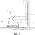
- the printing apparatus is comprised of the printer bed carriage 100 which comprises a carriage base 102 and at least one clamp 101 as well as at least one force member 300; the base plate 901 and the vertical plate 902 as well as the extrusion device 500 and the at least one linear bearing unit comprised by the linear rail 401 and the linear slide 402.
- the cross-sections of four force members are shown (only one is labelled). It is understood that the embodiment shown may comprise four or eight force members (as the force members may be paired). As can be seen in the figure the force members may be situated so that they are not equidistant from each other.
- the force members may be staggered so that the placement alternates on different locations on the base plate.
- at least some of the force members may be situated near the clamp and some force members at a greater distance from the clamp, e.g. having two rows of force members near the clamp and a single row of force members on the build plate centreline. The stability of the printing platform is beneficially affected by such an arrangement.
- the carriage base 100 is movably affixed to the base plate 901 by the linear bearing unit comprised of elements 401 and 402.
- the components may be attached to each other by at least any of the fastening means described in this disclosure.
- the base plate 901 is fixedly attached to the vertical plate 902 by any of the fastening means described in this disclosure.
- the vertical plate 902 is movably affixed to the extrusion device 500 which in the embodiment shown in Figure 3 is configured to move in the X-direction and Z-direction, that is sideways and upwards/ downwards as required by the printing process.
- the carriage base moves left and right as seen in the Figure 3 to facilitate the Cartesian range of motion required by the printing process.
- the carriage base 100 is fixedly or stationarily attached to the base plate 901 and the printing device is configured to have three axes of movement (X, Y, Z) for the extrusion head 500.
- the extrusion head moves in the XY directions and the carriage base moves in the vertical (Z) direction.
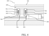
- two force members 700 and 300 are used to actuate the printing platform 200 into contact with the clamp 101.
- Clamp 101 is fixed to the apparatus via alternative supports means in accordance with the fastening means disclosed herein, which are not shown in the figure for the sake of clarity.
- the force members 700 and 300 may be substantially similar or they may differ in construction, measurements, type of mechanism utilized, etc.
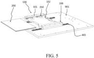
- leaf springs are used as the force members.
- at least one leaf spring 350 is situated so that it exerts an upward force on the printing platform 200 when the printing platform is inserted into the gap formed by the clamp 101 and the other clamp on the other side of the carriage base 102.
- the force results in the printing platform being pushed into contact with at least one surface of the clamp.
- at least one end stop 106 is used to prevent the printing platform from travelling too far with respect to the carriage base, i.e. the printing platform motion will be arrested when the leading edge contacts the end stop 106.
- the end stop may be used in any of the embodiments of this disclosure to prevent the printing platform from unwanted motion.
- the end stop may be implemented in any direction.
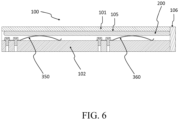
- a fourth exemplary embodiment is shown in cross-section wherein the force members 350 and 360 comprise leaf springs attached at one end by double bolts.
- the end stop 106 is shown preventing forward motion of the printing platform 200.
- the clamp 101 comprising the contact surface 105 is in contact with the upper surface of the printing platform 200.
- the force members 350 and 360 may be substantially similar or they may differ in construction, measurements, type of mechanism utilized, etc.
- the force member 350 comprises a leaf spring and the at least one bolt fixing the spring to the base 102.
- the contact surface 105 arrests the upward motion of the printing platform 105.
- the printing bed 200 may have at least one notch to accommodate the force member, for example a circular hole or groove to accommodate a rotating element e.g. the ball of a ball plunger.
- the at least one notch may be comprised on any surface of the printing bed, such as the side surfaces.
- at least one of the printing platform, clamp and carriage base may comprise at least rail such as a rail according to specification MIL-STD-1913. In such an embodiment, the friction during the printing process may be increased by configuring the force member to interact with the notches in the rail.
- the printing bed 200 may be immobilized during the printing process by the force member 300 in combination with another force member acting as the clamp 102.
- the friction required to be overcome for the insertion/removal operation is minimal, especially in the event that both the force member 300 and the clamp 102 incorporate a rotating element to contact the printing bed 200.
- An embodiment in accordance with any of the aspects of the invention is a fixture apparatus or kit which comprises the carriage bed 100, the force member 300 and the clamp 101.
- a fixture or kit apparatus may be used to retrofit existing 3D printers.
- the attachment mechanism disclosed herein allows for easy removal and insertion of the printing platform.
- a major benefit is that the removal and reinsertion of a printing platform does not require calibration, even in the event that the printing platform is swapped.
- the construction allows usage of cost-effective, simple build plates as printing platforms and doesn't require additional calibration or adjustment by users.
- the mechanism disclosed herein eliminates the need for calibration solutions such as: process solutions (homing), software solutions (calculation and alteration of paths to correct skew) and control solutions (sensors and/or calibration patterns).
- process solutions homoing
- software solutions calculation and alteration of paths to correct skew
- control solutions sensors and/or calibration patterns
- one type of controller may comprise, for example, at least one computing device such a server, node or cloud computing device.
- a processor which may comprise, for example, a single- or multi-core processor wherein a single-core processor comprises one processing core and a multi-core processor comprises more than one processing core.
- the processor may comprise more than one processor.
- a processing core may comprise, for example, a Cortex-A8 processing core by ARM Holdings or a Steamroller processing core produced by Advanced Micro Devices Corporation.
- the processor may comprise at least one Qualcomm Snapdragon and/or Intel Core processor, for example.
- the processor may comprise at least one application-specific integrated circuit, ASIC.
- the processor may comprise at least one field-programmable gate array, FPGA.
- the processor may be a means for performing method steps in the computing device.
- the processor may be configured, at least in part by computer instructions, to perform actions.
- control apparatus may comprise several devices in cooperation.
- the devices may interface via a network used to facilitate communication to and from control apparatuses, extrusion devices, radiation devices, measurement devices, meters, motors, gantries and other elements.
- Usable network technologies comprise: wireless local area network, WLAN, Ethernet, universal serial bus, USB, and/or worldwide interoperability for microwave access, WiMAX, standards, and satellite communication methods, direct wiring such as electrical wires, for example.
- a proprietary communication framework may be utilized.
- separate networks may be used for one or more of the following purposes: communication between control apparatuses, communication between control apparatuses and devices, communication between controllers and servers, et cetera.
- a programmable logic controller may be used as the controller of a 3D printing apparatus.
- the standard IEC 61131 defines programmable logic controllers, however, in the present disclosure the term PLC is not limited to the standard.
- the PLC may be connected to the devices by a variety of means, including but not limited to electrical wires.
- the process value of a device such as a extrusion device, motor, or radiation device may be adjusted according to various determination criteria comprising: preprogrammed instructions, communications received from other devices including the presence or absence of first or third party devices, presence and absence of personnel, elapsed time, preset time, measurements internal or external to the forming process, user inputs and timing, battery levels, network data, detected usage, planned usage or any combination thereof.
- Devices may also have preprogrammed activities or processes. These may be triggered based on the criteria listed above.
- At least some embodiments of the present invention find industrial application in three-dimensional fabrication of shapes or objects.
Landscapes
- Chemical & Material Sciences (AREA)
- Engineering & Computer Science (AREA)
- Materials Engineering (AREA)
- Manufacturing & Machinery (AREA)
- Physics & Mathematics (AREA)
- Mechanical Engineering (AREA)
- Optics & Photonics (AREA)
Claims (12)
- 3D-Drucker vom Extrusionstyp, umfassend eine Druckplattform-Befestigungsvorrichtung, wobei die Vorrichtung umfasst:- einen Druckplattformschlitten (100), der mindestens ein Kraftelement (300, 700) umfasst, das eingerichtet ist, um eine entfernbare Druckplattform (200) zu tragen und eine Kraft auf sie auszuüben,- mindestens eine Klemme (101);wobeidas mindestens eine Kraftelement (300, 700) ein Kugelstößel ist, undwobei der mindestens eine Kugelstößel (300, 700) eingerichtet ist, um eine entfernbare Druckplattform (200) derart zu tragen und eine Kraft auf sie auszuüben, dass mindestens eine Fläche der entfernbaren Druckplattform (200) mindestens eine Fläche (105) der Klemme (101) berührt.
- 3D-Drucker vom Extrusionstyp nach Anspruch 1, wobei die Druckplattform (200) aus Kunststoffmaterial besteht.
- 3D-Drucker vom Extrusionstyp nach einem der vorhergehenden Ansprüche, wobei die Vorrichtung 2-8 Kugelstößel (300, 700) umfasst.
- 3D-Drucker vom Extrusionstyp nach einem der vorhergehenden Ansprüche, wobei der mindestens eine Kugelstößel (300, 700) derart eingerichtet ist, dass die mindestens eine Fläche der entfernbaren Druckplattform (200) mindestens eine Fläche (105) der Klemme (101) auf der gegenüberliegenden Seite der Druckplattform (200) von dem Kugelstößel (300, 700) berühren wird.
- 3D-Drucker vom Extrusionstyp nach einem der vorhergehenden Ansprüche, wobei die Druckplattform (200) eine Dicke von 1 Millimeter bis 100 Millimeter, insbesondere von 2 bis 50 Millimeter, vorzugsweise von 3 bis 5 Millimeter, aufweist.
- 3D-Drucker vom Extrusionstyp nach einem der vorhergehenden Ansprüche, wobei die Klemme (101) ein durchgehendes Profil ist, das sich über die Länge des Druckerbettschlittens (100) erstreckt.
- 3D-Drucker vom Extrusionstyp nach einem der vorhergehenden Ansprüche, wobei die Gesamtkräfte der Kugelstößel (300, 700) 10-150 Newton, insbesondere 25-75, zum Beispiel etwa 33 Newton, betragen.
- 3D-Drucker vom Extrusionstyp nach einem der vorhergehenden Ansprüche, wobei die Klemme (101) fest an dem Druckplattformschlitten (100) angebracht ist oder ein integraler Bestandteil des Druckplattformschlittens (100) ist.
- 3D-Drucker vom Extrusionstyp nach einem der vorhergehenden Ansprüche, wobei der Druckplattformschlitten (100) einen Anschlag (106) umfasst, der eingerichtet ist, um die Druckplattform (200) an einer Bewegung in einer Richtung senkrecht zu dem Druckplattformschlitten (100) zu hindern.
- 3D-Drucker vom Extrusionstyp nach einem der vorhergehenden Ansprüche, wobei die Klemme (101) eine Kontaktfläche umfasst, die parallel zu der oberen Fläche des Druckplattformschlittens (200) oder parallel zu einer Referenzfläche einer 3D-Druckervorrichtung verläuft.
- 3D-Drucker vom Extrusionstyp nach einem der vorhergehenden Ansprüche, wobei die Vorrichtung mindestens zwei Klemmen (101) umfasst, wobei die Kontaktflächen der Klemmen koplanar zueinander angeordnet sind.
- Verwendung des 3D-Druckers vom Extrusionstyp nach einem der Ansprüche 1-9, wobei die entfernbare Druckplattform (200) zwischen dem mindestens einen Kugelstößel (300, 700) und der Klemme (101) eingesetzt ist.
Priority Applications (2)
| Application Number | Priority Date | Filing Date | Title |
|---|---|---|---|
| EP19154650.6A EP3689583B1 (de) | 2019-01-31 | 2019-01-31 | Vorrichtung zur befestigung einer druckplattform zur verwendung mit einem 3d-drucker |
| US16/776,635 US20200247050A1 (en) | 2019-01-31 | 2020-01-30 | Printing platform fixture apparatus for use with a 3D-printer |
Applications Claiming Priority (1)
| Application Number | Priority Date | Filing Date | Title |
|---|---|---|---|
| EP19154650.6A EP3689583B1 (de) | 2019-01-31 | 2019-01-31 | Vorrichtung zur befestigung einer druckplattform zur verwendung mit einem 3d-drucker |
Publications (3)
| Publication Number | Publication Date |
|---|---|
| EP3689583A1 EP3689583A1 (de) | 2020-08-05 |
| EP3689583C0 EP3689583C0 (de) | 2024-10-23 |
| EP3689583B1 true EP3689583B1 (de) | 2024-10-23 |
Family
ID=65268880
Family Applications (1)
| Application Number | Title | Priority Date | Filing Date |
|---|---|---|---|
| EP19154650.6A Active EP3689583B1 (de) | 2019-01-31 | 2019-01-31 | Vorrichtung zur befestigung einer druckplattform zur verwendung mit einem 3d-drucker |
Country Status (2)
| Country | Link |
|---|---|
| US (1) | US20200247050A1 (de) |
| EP (1) | EP3689583B1 (de) |
Families Citing this family (10)
| Publication number | Priority date | Publication date | Assignee | Title |
|---|---|---|---|---|
| US11493333B2 (en) * | 2019-12-06 | 2022-11-08 | Shanghai Fusion Tech Co., Ltd. | Flatness detection device |
| CN213082376U (zh) * | 2020-08-10 | 2021-04-30 | 深圳市创想三维科技有限公司 | 3d打印机调平组件和3d打印机 |
| CN111976014A (zh) * | 2020-08-18 | 2020-11-24 | 湖北光锐鑫光电科技有限公司 | 一种光学玻璃棒料开槽机 |
| WO2022090327A1 (en) * | 2020-10-28 | 2022-05-05 | Regenhu Ag | Carrier unit for an additive manufacturing device |
| CN112848300A (zh) * | 2021-01-07 | 2021-05-28 | 岳阳哈工三维科技有限公司 | 一种3d打印品质自动检测判断系统 |
| CN113231646B (zh) * | 2021-04-25 | 2023-01-31 | 西安建筑科技大学 | 基于电子束3D打印技术制备GCr15轴承钢及汽车部件的方法 |
| US11602894B2 (en) * | 2021-06-18 | 2023-03-14 | Essentium Ipco, Llc | Detecting lack of adhesion of a build plate to a support bed |
| NL2033245B1 (en) * | 2022-10-06 | 2024-04-19 | Ultimaker Bv | Print bed assembly for additive manufacturing system |
| CN115519786B (zh) * | 2022-10-14 | 2025-04-22 | 中国矿业大学 | 一种可吸收骨类植入物的3d打印装备及方法 |
| CN118269347B (zh) * | 2024-05-31 | 2024-08-02 | 东北石油大学 | 一种特种加工用3d打印设备 |
Family Cites Families (7)
| Publication number | Priority date | Publication date | Assignee | Title |
|---|---|---|---|---|
| DE29907262U1 (de) * | 1999-04-23 | 1999-07-15 | Eos Gmbh Electro Optical Systems, 82152 Planegg | Vorrichtung zum Herstellen eines dreidimensionalen Objektes mittels Rapid Prototyping |
| US20140085620A1 (en) * | 2012-09-24 | 2014-03-27 | Maxim Lobovsky | 3d printer with self-leveling platform |
| US9802360B2 (en) | 2013-06-04 | 2017-10-31 | Stratsys, Inc. | Platen planarizing process for additive manufacturing system |
| US10011076B2 (en) * | 2014-02-20 | 2018-07-03 | Global Filtration Systems | Apparatus and method for forming three-dimensional objects using a tilting solidification substrate |
| US9248600B2 (en) | 2014-05-28 | 2016-02-02 | Makerbot Industries, Llc | Build platform leveling and homing |
| NL2015361B1 (en) | 2015-08-28 | 2017-03-20 | Ultimaker Bv | Print bed levelling system and method for additive manufacturing. |
| CN109421253B (zh) * | 2017-08-21 | 2020-12-04 | 三纬国际立体列印科技股份有限公司 | 立体打印装置的成型平台 |
-
2019
- 2019-01-31 EP EP19154650.6A patent/EP3689583B1/de active Active
-
2020
- 2020-01-30 US US16/776,635 patent/US20200247050A1/en not_active Abandoned
Also Published As
| Publication number | Publication date |
|---|---|
| US20200247050A1 (en) | 2020-08-06 |
| EP3689583A1 (de) | 2020-08-05 |
| EP3689583C0 (de) | 2024-10-23 |
Similar Documents
| Publication | Publication Date | Title |
|---|---|---|
| EP3689583B1 (de) | Vorrichtung zur befestigung einer druckplattform zur verwendung mit einem 3d-drucker | |
| WO2015148665A1 (en) | Three-dimensional printer platform leveling apparatus and method | |
| EP3141345B1 (de) | Modulare und einstellbare gleitbasis | |
| CN107283828B (zh) | 3d打印装置、打印方法及其运动控制方法 | |
| WO2019077513A1 (en) | CONSTRUCTION PLATFORM GUIDE ARRANGEMENT FOR AN ADDITIVE MANUFACTURING APPARATUS | |
| CN108312531B (zh) | 横向3d打印机 | |
| CN114083470A (zh) | 一种大型机翼壁板无应力快速调姿装置及使用方法 | |
| KR100873469B1 (ko) | 마이크로 무금형 점진성형 소재 승강장치 | |
| US20170069525A1 (en) | Table device, measuring device, machine tool, and semiconductor manufacturing device | |
| CN113664759A (zh) | 一种硅钢片压装工装 | |
| CN204546860U (zh) | 一种顶针的加工治具 | |
| CN105729353A (zh) | 一种自适应柔性定位装置及定位方法 | |
| CN107953547B (zh) | 3d打印机及其快捷拆装喷头和快捷拆装组件 | |
| CN117359332A (zh) | 一种高精度立式坐标镗床横梁装配调整装置及方法 | |
| CN112297420A (zh) | 3d打印机 | |
| CN219404225U (zh) | 一种位移台 | |
| CN113210025B (zh) | 用于自动液体处理应用的可调安装件 | |
| CN216298510U (zh) | 一种视觉伺服的锁螺丝机器人 | |
| CN211491529U (zh) | 一种平面坐标调节机构 | |
| CN213646526U (zh) | 高精度装配装置 | |
| CN210121687U (zh) | 一种基于斜坡原理的车刀调高装置 | |
| CN116456595A (zh) | 电路板加工设备及其控制方法、主轴偏差调整装置 | |
| CN209078702U (zh) | 一种精密定位加工平台 | |
| CN223038407U (zh) | 读码移动装置和光伏玻璃读码设备 | |
| CN208133620U (zh) | 横向3d打印机 |
Legal Events
| Date | Code | Title | Description |
|---|---|---|---|
| PUAI | Public reference made under article 153(3) epc to a published international application that has entered the european phase |
Free format text: ORIGINAL CODE: 0009012 |
|
| STAA | Information on the status of an ep patent application or granted ep patent |
Free format text: STATUS: THE APPLICATION HAS BEEN PUBLISHED |
|
| AK | Designated contracting states |
Kind code of ref document: A1 Designated state(s): AL AT BE BG CH CY CZ DE DK EE ES FI FR GB GR HR HU IE IS IT LI LT LU LV MC MK MT NL NO PL PT RO RS SE SI SK SM TR |
|
| AX | Request for extension of the european patent |
Extension state: BA ME |
|
| STAA | Information on the status of an ep patent application or granted ep patent |
Free format text: STATUS: REQUEST FOR EXAMINATION WAS MADE |
|
| 17P | Request for examination filed |
Effective date: 20210205 |
|
| RBV | Designated contracting states (corrected) |
Designated state(s): AL AT BE BG CH CY CZ DE DK EE ES FI FR GB GR HR HU IE IS IT LI LT LU LV MC MK MT NL NO PL PT RO RS SE SI SK SM TR |
|
| GRAP | Despatch of communication of intention to grant a patent |
Free format text: ORIGINAL CODE: EPIDOSNIGR1 |
|
| STAA | Information on the status of an ep patent application or granted ep patent |
Free format text: STATUS: GRANT OF PATENT IS INTENDED |
|
| RIC1 | Information provided on ipc code assigned before grant |
Ipc: B23Q 1/01 20060101ALN20221031BHEP Ipc: B28D 7/04 20060101ALN20221031BHEP Ipc: B33Y 30/00 20150101ALI20221031BHEP Ipc: B29C 64/245 20170101AFI20221031BHEP |
|
| RIC1 | Information provided on ipc code assigned before grant |
Ipc: B23Q 1/01 20060101ALN20221107BHEP Ipc: B28D 7/04 20060101ALN20221107BHEP Ipc: B33Y 30/00 20150101ALI20221107BHEP Ipc: B29C 64/245 20170101AFI20221107BHEP |
|
| RIC1 | Information provided on ipc code assigned before grant |
Ipc: B23Q 1/01 20060101ALN20221117BHEP Ipc: B28D 7/04 20060101ALN20221117BHEP Ipc: B33Y 30/00 20150101ALI20221117BHEP Ipc: B29C 64/245 20170101AFI20221117BHEP |
|
| INTG | Intention to grant announced |
Effective date: 20221202 |
|
| GRAJ | Information related to disapproval of communication of intention to grant by the applicant or resumption of examination proceedings by the epo deleted |
Free format text: ORIGINAL CODE: EPIDOSDIGR1 |
|
| STAA | Information on the status of an ep patent application or granted ep patent |
Free format text: STATUS: REQUEST FOR EXAMINATION WAS MADE |
|
| INTC | Intention to grant announced (deleted) | ||
| GRAP | Despatch of communication of intention to grant a patent |
Free format text: ORIGINAL CODE: EPIDOSNIGR1 |
|
| STAA | Information on the status of an ep patent application or granted ep patent |
Free format text: STATUS: GRANT OF PATENT IS INTENDED |
|
| RIC1 | Information provided on ipc code assigned before grant |
Ipc: B23Q 1/01 20060101ALN20231002BHEP Ipc: B28D 7/04 20060101ALN20231002BHEP Ipc: B33Y 30/00 20150101ALI20231002BHEP Ipc: B29C 64/245 20170101AFI20231002BHEP |
|
| INTG | Intention to grant announced |
Effective date: 20231020 |
|
| 19U | Interruption of proceedings before grant |
Effective date: 20231110 |
|
| 19W | Proceedings resumed before grant after interruption of proceedings |
Effective date: 20240801 |
|
| RAP3 | Party data changed (applicant data changed or rights of an application transferred) |
Owner name: CURIFYLABS OY |
|
| GRAS | Grant fee paid |
Free format text: ORIGINAL CODE: EPIDOSNIGR3 |
|
| GRAA | (expected) grant |
Free format text: ORIGINAL CODE: 0009210 |
|
| STAA | Information on the status of an ep patent application or granted ep patent |
Free format text: STATUS: THE PATENT HAS BEEN GRANTED |
|
| AK | Designated contracting states |
Kind code of ref document: B1 Designated state(s): AL AT BE BG CH CY CZ DE DK EE ES FI FR GB GR HR HU IE IS IT LI LT LU LV MC MK MT NL NO PL PT RO RS SE SI SK SM TR |
|
| REG | Reference to a national code |
Ref country code: GB Ref legal event code: FG4D |
|
| RIN1 | Information on inventor provided before grant (corrected) |
Inventor name: HEINO, PETRI Inventor name: MEHTA, SANTOSH |
|
| REG | Reference to a national code |
Ref country code: CH Ref legal event code: EP |
|
| REG | Reference to a national code |
Ref country code: DE Ref legal event code: R096 Ref document number: 602019060695 Country of ref document: DE |
|
| REG | Reference to a national code |
Ref country code: IE Ref legal event code: FG4D |
|
| U01 | Request for unitary effect filed |
Effective date: 20241119 |
|
| U07 | Unitary effect registered |
Designated state(s): AT BE BG DE DK EE FI FR IT LT LU LV MT NL PT RO SE SI Effective date: 20241125 |
|
| U1N | Appointed representative for the unitary patent procedure changed after the registration of the unitary effect |
Representative=s name: LAINE IP OY; FI |
|
| U20 | Renewal fee for the european patent with unitary effect paid |
Year of fee payment: 7 Effective date: 20250128 |
|
| PG25 | Lapsed in a contracting state [announced via postgrant information from national office to epo] |
Ref country code: IS Free format text: LAPSE BECAUSE OF FAILURE TO SUBMIT A TRANSLATION OF THE DESCRIPTION OR TO PAY THE FEE WITHIN THE PRESCRIBED TIME-LIMIT Effective date: 20250223 Ref country code: HR Free format text: LAPSE BECAUSE OF FAILURE TO SUBMIT A TRANSLATION OF THE DESCRIPTION OR TO PAY THE FEE WITHIN THE PRESCRIBED TIME-LIMIT Effective date: 20241023 |
|
| PG25 | Lapsed in a contracting state [announced via postgrant information from national office to epo] |
Ref country code: ES Free format text: LAPSE BECAUSE OF FAILURE TO SUBMIT A TRANSLATION OF THE DESCRIPTION OR TO PAY THE FEE WITHIN THE PRESCRIBED TIME-LIMIT Effective date: 20241023 |
|
| PG25 | Lapsed in a contracting state [announced via postgrant information from national office to epo] |
Ref country code: NO Free format text: LAPSE BECAUSE OF FAILURE TO SUBMIT A TRANSLATION OF THE DESCRIPTION OR TO PAY THE FEE WITHIN THE PRESCRIBED TIME-LIMIT Effective date: 20250123 |
|
| PG25 | Lapsed in a contracting state [announced via postgrant information from national office to epo] |
Ref country code: GR Free format text: LAPSE BECAUSE OF FAILURE TO SUBMIT A TRANSLATION OF THE DESCRIPTION OR TO PAY THE FEE WITHIN THE PRESCRIBED TIME-LIMIT Effective date: 20250124 |
|
| PG25 | Lapsed in a contracting state [announced via postgrant information from national office to epo] |
Ref country code: PL Free format text: LAPSE BECAUSE OF FAILURE TO SUBMIT A TRANSLATION OF THE DESCRIPTION OR TO PAY THE FEE WITHIN THE PRESCRIBED TIME-LIMIT Effective date: 20241023 |
|
| PG25 | Lapsed in a contracting state [announced via postgrant information from national office to epo] |
Ref country code: RS Free format text: LAPSE BECAUSE OF FAILURE TO SUBMIT A TRANSLATION OF THE DESCRIPTION OR TO PAY THE FEE WITHIN THE PRESCRIBED TIME-LIMIT Effective date: 20250123 |
|
| PG25 | Lapsed in a contracting state [announced via postgrant information from national office to epo] |
Ref country code: SM Free format text: LAPSE BECAUSE OF FAILURE TO SUBMIT A TRANSLATION OF THE DESCRIPTION OR TO PAY THE FEE WITHIN THE PRESCRIBED TIME-LIMIT Effective date: 20241023 |
|
| PG25 | Lapsed in a contracting state [announced via postgrant information from national office to epo] |
Ref country code: SK Free format text: LAPSE BECAUSE OF FAILURE TO SUBMIT A TRANSLATION OF THE DESCRIPTION OR TO PAY THE FEE WITHIN THE PRESCRIBED TIME-LIMIT Effective date: 20241023 |
|
| PG25 | Lapsed in a contracting state [announced via postgrant information from national office to epo] |
Ref country code: CZ Free format text: LAPSE BECAUSE OF FAILURE TO SUBMIT A TRANSLATION OF THE DESCRIPTION OR TO PAY THE FEE WITHIN THE PRESCRIBED TIME-LIMIT Effective date: 20241023 |
|
| PLBE | No opposition filed within time limit |
Free format text: ORIGINAL CODE: 0009261 |
|
| REG | Reference to a national code |
Ref country code: CH Ref legal event code: PL |
|
| STAA | Information on the status of an ep patent application or granted ep patent |
Free format text: STATUS: NO OPPOSITION FILED WITHIN TIME LIMIT |
|
| PG25 | Lapsed in a contracting state [announced via postgrant information from national office to epo] |
Ref country code: MC Free format text: LAPSE BECAUSE OF FAILURE TO SUBMIT A TRANSLATION OF THE DESCRIPTION OR TO PAY THE FEE WITHIN THE PRESCRIBED TIME-LIMIT Effective date: 20241023 |
|
| GBPC | Gb: european patent ceased through non-payment of renewal fee |
Effective date: 20250131 |
|
| 26N | No opposition filed |
Effective date: 20250724 |
|
| PG25 | Lapsed in a contracting state [announced via postgrant information from national office to epo] |
Ref country code: GB Free format text: LAPSE BECAUSE OF NON-PAYMENT OF DUE FEES Effective date: 20250131 |
|
| PG25 | Lapsed in a contracting state [announced via postgrant information from national office to epo] |
Ref country code: CH Free format text: LAPSE BECAUSE OF NON-PAYMENT OF DUE FEES Effective date: 20250131 |
|
| PG25 | Lapsed in a contracting state [announced via postgrant information from national office to epo] |
Ref country code: IE Free format text: LAPSE BECAUSE OF NON-PAYMENT OF DUE FEES Effective date: 20250131 |
|
| U20 | Renewal fee for the european patent with unitary effect paid |
Year of fee payment: 8 Effective date: 20260107 |