EP3689542B1 - A method for grinding and polishing glass sheets - Google Patents
A method for grinding and polishing glass sheets Download PDFInfo
- Publication number
- EP3689542B1 EP3689542B1 EP20155015.9A EP20155015A EP3689542B1 EP 3689542 B1 EP3689542 B1 EP 3689542B1 EP 20155015 A EP20155015 A EP 20155015A EP 3689542 B1 EP3689542 B1 EP 3689542B1
- Authority
- EP
- European Patent Office
- Prior art keywords
- grinding
- polishing
- wheels
- wheel
- limit value
- Prior art date
- Legal status (The legal status is an assumption and is not a legal conclusion. Google has not performed a legal analysis and makes no representation as to the accuracy of the status listed.)
- Active
Links
Images
Classifications
-
- B—PERFORMING OPERATIONS; TRANSPORTING
- B24—GRINDING; POLISHING
- B24B—MACHINES, DEVICES, OR PROCESSES FOR GRINDING OR POLISHING; DRESSING OR CONDITIONING OF ABRADING SURFACES; FEEDING OF GRINDING, POLISHING, OR LAPPING AGENTS
- B24B9/00—Machines or devices designed for grinding edges or bevels on work or for removing burrs; Accessories therefor
- B24B9/002—Machines or devices designed for grinding edges or bevels on work or for removing burrs; Accessories therefor for travelling workpieces
-
- B—PERFORMING OPERATIONS; TRANSPORTING
- B24—GRINDING; POLISHING
- B24B—MACHINES, DEVICES, OR PROCESSES FOR GRINDING OR POLISHING; DRESSING OR CONDITIONING OF ABRADING SURFACES; FEEDING OF GRINDING, POLISHING, OR LAPPING AGENTS
- B24B49/00—Measuring or gauging equipment for controlling the feed movement of the grinding tool or work; Arrangements of indicating or measuring equipment, e.g. for indicating the start of the grinding operation
- B24B49/10—Measuring or gauging equipment for controlling the feed movement of the grinding tool or work; Arrangements of indicating or measuring equipment, e.g. for indicating the start of the grinding operation involving electrical means
-
- B—PERFORMING OPERATIONS; TRANSPORTING
- B24—GRINDING; POLISHING
- B24B—MACHINES, DEVICES, OR PROCESSES FOR GRINDING OR POLISHING; DRESSING OR CONDITIONING OF ABRADING SURFACES; FEEDING OF GRINDING, POLISHING, OR LAPPING AGENTS
- B24B49/00—Measuring or gauging equipment for controlling the feed movement of the grinding tool or work; Arrangements of indicating or measuring equipment, e.g. for indicating the start of the grinding operation
- B24B49/16—Measuring or gauging equipment for controlling the feed movement of the grinding tool or work; Arrangements of indicating or measuring equipment, e.g. for indicating the start of the grinding operation taking regard of the load
-
- B—PERFORMING OPERATIONS; TRANSPORTING
- B24—GRINDING; POLISHING
- B24B—MACHINES, DEVICES, OR PROCESSES FOR GRINDING OR POLISHING; DRESSING OR CONDITIONING OF ABRADING SURFACES; FEEDING OF GRINDING, POLISHING, OR LAPPING AGENTS
- B24B55/00—Safety devices for grinding or polishing machines; Accessories fitted to grinding or polishing machines for keeping tools or parts of the machine in good working condition
-
- B—PERFORMING OPERATIONS; TRANSPORTING
- B24—GRINDING; POLISHING
- B24B—MACHINES, DEVICES, OR PROCESSES FOR GRINDING OR POLISHING; DRESSING OR CONDITIONING OF ABRADING SURFACES; FEEDING OF GRINDING, POLISHING, OR LAPPING AGENTS
- B24B9/00—Machines or devices designed for grinding edges or bevels on work or for removing burrs; Accessories therefor
- B24B9/02—Machines or devices designed for grinding edges or bevels on work or for removing burrs; Accessories therefor characterised by a special design with respect to properties of materials specific to articles to be ground
- B24B9/06—Machines or devices designed for grinding edges or bevels on work or for removing burrs; Accessories therefor characterised by a special design with respect to properties of materials specific to articles to be ground of non-metallic inorganic material, e.g. stone, ceramics, porcelain
- B24B9/08—Machines or devices designed for grinding edges or bevels on work or for removing burrs; Accessories therefor characterised by a special design with respect to properties of materials specific to articles to be ground of non-metallic inorganic material, e.g. stone, ceramics, porcelain of glass
- B24B9/10—Machines or devices designed for grinding edges or bevels on work or for removing burrs; Accessories therefor characterised by a special design with respect to properties of materials specific to articles to be ground of non-metallic inorganic material, e.g. stone, ceramics, porcelain of glass of plate glass
- B24B9/102—Machines or devices designed for grinding edges or bevels on work or for removing burrs; Accessories therefor characterised by a special design with respect to properties of materials specific to articles to be ground of non-metallic inorganic material, e.g. stone, ceramics, porcelain of glass of plate glass for travelling sheets
Definitions
- This invention relates to a method for grinding and polishing glass sheets.
- this invention relates to a method for grinding and polishing perimeter or lateral surfaces of a glass sheet, i.e. those surfaces that extend orthogonally to the extended surfaces of the same glass sheet.
- the so-called "bilateral" machines belong to a first type. With these, the sheets are fed flat and the opposite perimeter surfaces thereof are ground simultaneously and progressively by two rows of grinding wheels, which face each other and are arranged in a grinding station of the machine.
- the so-called "rectilinear" grinding machines belong to a second type, wherein the sheets are fed edgeways and they are ground by progressively feeding the perimeter surfaces onto an underlying row of grinding wheels, which are also arranged in a grinding station of the machine.
- each row of wheels comprises a plurality of grinding wheels and a plurality of polishing wheels arranged downstream of the grinding wheels to polish the surfaces grounded by the grinding wheels.
- Both the grinding and polishing wheels rotate around their respective rotation axes, each under the thrust of a corresponding electric drive motor.
- Each grinding wheel is arranged in its own operative grinding position to remove a pre-set portion of glass from the sheet, while each polishing wheel is constantly thrust against a corresponding perimeter surface that has previously been ground so as to polish the corresponding perimeter surface itself.
- Both grinding and polishing wheels are different both in terms of the abrasive capacity thereof and in terms of the abrasive material and/or matrix wherein this abrasive material is dispersed. This is due to the fact that each wheel supplier offers wheels of their own design and with their own features. The user generally uses wheels from different suppliers depending on the processing to be carried out on the glass sheet.
- both abrasive and polishing wheels progressively wear out over time but in a different way from each other, precisely because of their different designs.
- a machine safety device or rather a protection device, for the electric motor(s) of the grinding wheel(s) concerned, automatically intervenes.
- This safety device isolates the electric motors and, at the same time, stops the entire machine, effectively blocking production.
- Stopping the machine is absolutely to be avoided because the subsequent restart requires that all of the sheets, even a few dozen, present in the machine be removed.
- This removal as well as requiring an extremely long time since the machine must first be secured and then brought into an "opening" or "processing sheets extraction” condition, leads, at the same time, to a considerable loss of sheets from the batch being processed.
- the sheets, all already partially processed, must, in fact, be thrown away and reintegrated with other sheets to ensure the expected number of sheets in the batch. All the operations described above significantly increase the batch's production time and cost, with obvious economic losses.
- edge grinding and polishing wheels as the machine also has an edge grinding assembly.
- the purpose of this invention is to provide a method for grinding and polishing glass sheets, which avoids the removal of sheets being processed on the machine and the discarding of sheets, or pieces of sheets, already partially processed due to the machine's being unexpectedly stopped when abnormal grinding and/or polishing conditions occur.
- a method for grinding and polishing glass sheets comprising the steps of feeding a succession of glass sheets in a longitudinal direction at a given speed rate; progressively grinding at least one perimeter surface of the glass sheets by means of one or more grinding wheels independent of one another, the grinding comprising the step of rotating each grinding wheel about a rotation axis thereof by means of a respective grinding electric motor and by moving each sheet and the grinding wheel or wheels relative to one another at a given relative grinding speed; and polishing the ground surface with said grinding wheel or wheels by means of one or more polishing wheels rotated about the respective axes by respective polishing electric motors; the polishing comprising the step of exerting a predefined thrust action directed towards said glass sheet on each polishing wheel and moving each sheet or polishing wheel or wheels relative to one another at a respective polishing speed; the method further comprising a control step, in turn, comprising the step of detecting the current absorbed by at least a first of the electric motors during the processing of said sheets, and being characterized in that said
- reference number 1 indicates, as a whole, a machine for grinding and polishing glass sheets 2: flat, rectangular glass sheets with two opposing, extended, flat surfaces, indicated with 3, and four consecutive, flat perimeter or lateral surfaces, one of which is indicated with reference number 5, in the illustrated example.
- the machine 1 can, equally, be a bilateral machine, i.e. with sheets 2 fed flat, or a straight machine, i.e. with sheets 2 fed edgeways. It comprises a stiff, straight structure 6, and a motorized sheet conveying assembly 7, known in itself and partially visible in the attached figures, to feed a succession 8 of sheets 2 to be ground along a straight path 6A.
- the assembly 7 comprises an input conveyor 9 for the sheets 2 to be ground, an output conveyor 10 for the ground sheets, and an intermediate conveyor 11 for retaining and feeding sheets 2.
- the conveyor 11 moves the sheets 2 to be ground through a station 13 for grinding and polishing the perimeter surfaces 5 arranged along the feeding path 6A, taking the sheets 2 from one entrance 14 to the station 13.
- the conveyor 11 also feeds the sheets 2 through an additional grinding and polishing station 15, which is arranged downstream of the station 13 in a feeding direction K for the sheets 2 and in which the edges 5A of the sheets 2 are ground and polished.
- the conveyor 11 is commanded and controlled by an electronic command and control unit 16 for feeding the sheets 2 at a pre-set, constant speed chosen, for example, according to the thickness of the glass, the degree of finish, and the number of wheels used.
- the passage of a head and a tail of each of the sheets 2 entering the station 13 is detected by a presence sensor 17 connected to the electronic unit 16.
- the station 13 houses a row 18 of abrasive assemblies, known in themselves, which are independent of one another and arranged side-by-side in a direction parallel to the path 6A.
- the row 18 of abrasive assemblies comprises a set A of grinding assemblies 19, and a set B of polishing assemblies 20, which polish the surfaces 5 ground by the set A.
- Each of the grinding assemblies 19 is a unit independent of the other units and comprises a grinding wheel 22, which has an abrasive surface 22A thereof and is rotated about an axis M thereof that is orthogonal to the path 6A by a respective electric motor 23 commanded by the electronic unit 16.
- Each abrasive wheel 22A is carried by a relative slide 24, which is slidably coupled to the frame 6 of the machine 1 and in opposite directions along the relative axis M under the thrust of a servomotor 25 controlled by the electronic command and control unit 16.
- Each of the polishing assemblies 20 is an independent unit and comprises a respective polishing wheel 27, which has a polishing surface 27A thereof and is rotated about an axis N thereof that is orthogonal to the path 6A by a respective electric motor 28 commanded by the electronic unit 16.
- the wheel 27 of each assembly 20 is mounted on a relative mobile slide 26 in a direction parallel to the axes N.
- Each slide 26 is driven by its own actuator 29, for example, a pneumatic cylinder controlled by a proportional solenoid valve controlled by the electronic unit 16 to push the polishing surface 27A of the corresponding wheel 27 against the surface 5 of the sheets 2.
- the machine 1 comprises an edge 5A grinding and polishing assembly 30.
- the assembly 30, which is known in itself and not described in detail, comprises a shaft 31, which is driven by means of an electric motor 32 and has two wheels, known in themselves, that are coupled together. One of the latter is a grinding wheel, indicated with 33, and one a polishing wheel, indicated with 34.
- the shaft 31 is carried by a motorised slide, which is mobile in two directions orthogonal to each other and one of which is parallel to the path 6A to move the wheels 33,34 with respect to a sheet to be processed at a pre-set relative speed, which is generally constant. According to a different production method, the machine 1 does not have the assembly 30.
- the electronic unit 16 comprises a detecting block 35 to detect the instantaneous absorbed current value for each of the electric motors 23, 28, and 32.
- the electronic unit 16 also comprises a memory block 36 in which an absorbable current limit value of the respective electric motor is stored for each grinding wheel and for each polishing wheel.
- Each absorbable current limit value is determined experimentally by considering the chemical-physical features of the glass sheets 2, the features of the wheels used, such as the type and concentration of the abrasive grain and/or the type of matrix wherein the abrasive material is included, and the expected amount of material to be removed in order to obtain an optimal ratio between abrasive/polishing activity and wear.
- the absorbable current limit value also takes into account the value of the polishing wheel thrust force against the surface 5 of the sheet 2.
- the absorbable current limit values are all lower than a safety limit value, at the occurrence of which the machine 1 is stopped by a motor protection and machine safety device, indicated by the reference number 39.
- the thrust values of each of the polishing wheels are stored in a block 40 of the electronic unit 16.
- the electronic unit 16 comprises a comparator block 41 that continuously compares the absorbed current value for each electric motor and the corresponding stored absorbable current limit value.
- the electronic unit 16 In use, starting from a condition wherein the sheets 2 are fed along the path 6A and progressively ground by the grinding assembly A and then polished by the polishing assemblies B, the electronic unit 16 detects the values of current absorbed by each of the motors 23 and 28. If, during a control step, none of the absorbed current values exceeds the corresponding stored absorbable current value, the grinding and polishing process continues in the ordinary manner.
- the electronic unit 16 continues the control step and intervenes, in an automatic manner, by reducing the speed rate of the sheets 2, if the threshold exceedance concerns a grinding wheel, or by reducing the thrust action of the wheel against the sheet 2, if the threshold exceedance concerns a polishing wheel.
- the reduction in the speed rate of the glass sheets 2 translates into a reduction in the quantity of material removed from the individual grinding wheel, since the removal capacity of a grinding wheel is expressed in cubic centimetres over the unit of time, which is equivalent to the wheel-sheet contact surface expressed in square centimetres for the speed rate of the glass sheets 2.
- reducing the thrust action of the polishing wheels 27 is equivalent to reducing the aggressiveness of the polishing action.
- the same electric motor can always rotate the same wheel, or any wheel of a series or family of wheels that are equal or different in terms of size, and/or constructively different from each other with regard to the matrix, the abrasive material, and the concentration of the abrasive material itself in the matrix and, more generally, wheels from different wheel suppliers.
- a plurality of identification codes is stored in the memory block 36, each of which identifies one of the wheels in the series of wheels and, for each of the same wheels, a corresponding absorbable current limit value for the electric motor is also stored.
- the electronic unit 16 conveniently comprises a keyboard 42, by means of which an operator, noting the wheel associated with the electric motor, selects one of the stored identification codes and consequently communicates to the comparator block 41 the corresponding absorbable current limit value to be used in the comparison.
- the electronic unit 16 itself comprises a detector block 43 that automatically and autonomously detects the wheel of the series of wheels driven by the electric motor and sends a corresponding signal to the comparator block 41.
- the reduction in thrust can also be applied to the polishing wheel 34 of the assembly 30 for processing the edges 5A, while an increase in the current absorbed by the motor 32 during the operation of the grinding wheel 33 can be limited by progressively reducing the speed at which the grinding wheel moves with respect to the sheet, i.e. by reducing the relative speed of the grinding wheel-sheet, which, for practical purposes, is equivalent to the slowing down of the glass sheets 2 in the grinding assemblies A for the surfaces 5A.
- the grinding and polishing method described above applies, irrespective of the devices used, either to adjust the position of the wheels 22 or to move the wheels 33 and 34 in relation to the sheet, and to push the wheels 27 or wheel 34 towards the ground surface and the surface to be polished.
- grinding wheels 22 can be moved to and from the sheet by manual devices as well, while the polishing wheels 27, 34 can be thrust by mechanical springs, with the possibility of varying the pre-load thereof, or by torque controlled electric motors.
Landscapes
- Engineering & Computer Science (AREA)
- Mechanical Engineering (AREA)
- Chemical & Material Sciences (AREA)
- Ceramic Engineering (AREA)
- Inorganic Chemistry (AREA)
- Grinding And Polishing Of Tertiary Curved Surfaces And Surfaces With Complex Shapes (AREA)
- Constituent Portions Of Griding Lathes, Driving, Sensing And Control (AREA)
- Grinding Of Cylindrical And Plane Surfaces (AREA)
- Polishing Bodies And Polishing Tools (AREA)
Description
- This invention relates to a method for grinding and polishing glass sheets.
- In particular, this invention relates to a method for grinding and polishing perimeter or lateral surfaces of a glass sheet, i.e. those surfaces that extend orthogonally to the extended surfaces of the same glass sheet.
- As is known, two types of machines are known for use in processing the above-mentioned perimeter surfaces. On the one hand, the so-called "bilateral" machines belong to a first type. With these, the sheets are fed flat and the opposite perimeter surfaces thereof are ground simultaneously and progressively by two rows of grinding wheels, which face each other and are arranged in a grinding station of the machine.
- The so-called "rectilinear" grinding machines, on the other hand, belong to a second type, wherein the sheets are fed edgeways and they are ground by progressively feeding the perimeter surfaces onto an underlying row of grinding wheels, which are also arranged in a grinding station of the machine.
- Irrespective of the type of machine used, each row of wheels comprises a plurality of grinding wheels and a plurality of polishing wheels arranged downstream of the grinding wheels to polish the surfaces grounded by the grinding wheels.
- Both the grinding and polishing wheels rotate around their respective rotation axes, each under the thrust of a corresponding electric drive motor.
- Each grinding wheel is arranged in its own operative grinding position to remove a pre-set portion of glass from the sheet, while each polishing wheel is constantly thrust against a corresponding perimeter surface that has previously been ground so as to polish the corresponding perimeter surface itself.
- Both grinding and polishing wheels are different both in terms of the abrasive capacity thereof and in terms of the abrasive material and/or matrix wherein this abrasive material is dispersed. This is due to the fact that each wheel supplier offers wheels of their own design and with their own features. The user generally uses wheels from different suppliers depending on the processing to be carried out on the glass sheet.
- Obviously, both abrasive and polishing wheels progressively wear out over time but in a different way from each other, precisely because of their different designs.
- During the grinding and subsequent polishing, however, unforeseeable critical working conditions often occur that are caused, for example, by mistakes made when entering input or instruction data or as a result of the replacement of the wheel. The above-mentioned critical conditions generally produce an increase in the amount of material to be removed or in the formation of imperfections on the processed surface. This mainly results from the lack of, or only partial, processing carried out by one or more wheels arranged upstream of a particular wheel, with inevitable peaks in the current absorbed by the motors concerned.
- When such critical conditions occur, a machine safety device, or rather a protection device, for the electric motor(s) of the grinding wheel(s) concerned, automatically intervenes. This safety device isolates the electric motors and, at the same time, stops the entire machine, effectively blocking production.
- Stopping the machine is absolutely to be avoided because the subsequent restart requires that all of the sheets, even a few dozen, present in the machine be removed. This removal, as well as requiring an extremely long time since the machine must first be secured and then brought into an "opening" or "processing sheets extraction" condition, leads, at the same time, to a considerable loss of sheets from the batch being processed. The sheets, all already partially processed, must, in fact, be thrown away and reintegrated with other sheets to ensure the expected number of sheets in the batch. All the operations described above significantly increase the batch's production time and cost, with obvious economic losses.
- Similar considerations also apply to edge grinding and polishing wheels, as the machine also has an edge grinding assembly.
- Different methods for working glass sheets are disclosed in
EP 0 689 899 A1 , inJP 2003 117815 A EP 2 666 591 A1 - The purpose of this invention is to provide a method for grinding and polishing glass sheets, which avoids the removal of sheets being processed on the machine and the discarding of sheets, or pieces of sheets, already partially processed due to the machine's being unexpectedly stopped when abnormal grinding and/or polishing conditions occur.
- According to the present invention, a method is provided for grinding and polishing glass sheets, the method comprising the steps of feeding a succession of glass sheets in a longitudinal direction at a given speed rate; progressively grinding at least one perimeter surface of the glass sheets by means of one or more grinding wheels independent of one another, the grinding comprising the step of rotating each grinding wheel about a rotation axis thereof by means of a respective grinding electric motor and by moving each sheet and the grinding wheel or wheels relative to one another at a given relative grinding speed; and polishing the ground surface with said grinding wheel or wheels by means of one or more polishing wheels rotated about the respective axes by respective polishing electric motors; the polishing comprising the step of exerting a predefined thrust action directed towards said glass sheet on each polishing wheel and moving each sheet or polishing wheel or wheels relative to one another at a respective polishing speed; the method further comprising a control step, in turn, comprising the step of detecting the current absorbed by at least a first of the electric motors during the processing of said sheets, and being characterized in that said control step comprises the operations of establishing, for at least the first of said electric motors, a respective absorbable current limit value, of comparing the respective said absorbable current limit value with the value of current absorbed by said first motor and of reducing at least one of either the speed or said thrust action when said measured current value exceeds said absorbable current limit value by continuing to feed the succession of glass sheets in said longitudinal direction.
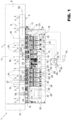
- The invention will now be described with reference to the attached figure, which shows a glass sheet grinding and polishing machine for the implementation of a preferred embodiment of the method for grinding and polishing glass sheets according to the principles of this invention.
- In the attached figure, the
reference number 1 indicates, as a whole, a machine for grinding and polishing glass sheets 2: flat, rectangular glass sheets with two opposing, extended, flat surfaces, indicated with 3, and four consecutive, flat perimeter or lateral surfaces, one of which is indicated withreference number 5, in the illustrated example. - The
machine 1 can, equally, be a bilateral machine, i.e. withsheets 2 fed flat, or a straight machine, i.e. withsheets 2 fed edgeways. It comprises a stiff,straight structure 6, and a motorizedsheet conveying assembly 7, known in itself and partially visible in the attached figures, to feed asuccession 8 ofsheets 2 to be ground along astraight path 6A. In this particular case, theassembly 7 comprises aninput conveyor 9 for thesheets 2 to be ground, anoutput conveyor 10 for the ground sheets, and anintermediate conveyor 11 for retaining andfeeding sheets 2. - The
conveyor 11 moves thesheets 2 to be ground through a station 13 for grinding and polishing theperimeter surfaces 5 arranged along thefeeding path 6A, taking thesheets 2 from oneentrance 14 to the station 13. Theconveyor 11 also feeds thesheets 2 through an additional grinding andpolishing station 15, which is arranged downstream of the station 13 in a feeding direction K for thesheets 2 and in which theedges 5A of thesheets 2 are ground and polished. - The
conveyor 11 is commanded and controlled by an electronic command andcontrol unit 16 for feeding thesheets 2 at a pre-set, constant speed chosen, for example, according to the thickness of the glass, the degree of finish, and the number of wheels used. The passage of a head and a tail of each of thesheets 2 entering the station 13 is detected by apresence sensor 17 connected to theelectronic unit 16. - Again with reference to
Figure 1 , the station 13 houses arow 18 of abrasive assemblies, known in themselves, which are independent of one another and arranged side-by-side in a direction parallel to thepath 6A. Therow 18 of abrasive assemblies comprises a set A ofgrinding assemblies 19, and a set B ofpolishing assemblies 20, which polish thesurfaces 5 ground by the set A. - Each of the
grinding assemblies 19 is a unit independent of the other units and comprises agrinding wheel 22, which has an abrasive surface 22A thereof and is rotated about an axis M thereof that is orthogonal to thepath 6A by a respectiveelectric motor 23 commanded by theelectronic unit 16. - Each abrasive wheel 22A is carried by a
relative slide 24, which is slidably coupled to theframe 6 of themachine 1 and in opposite directions along the relative axis M under the thrust of aservomotor 25 controlled by the electronic command andcontrol unit 16. - Each of the
polishing assemblies 20 is an independent unit and comprises arespective polishing wheel 27, which has apolishing surface 27A thereof and is rotated about an axis N thereof that is orthogonal to thepath 6A by a respectiveelectric motor 28 commanded by theelectronic unit 16. Thewheel 27 of eachassembly 20 is mounted on a relativemobile slide 26 in a direction parallel to the axes N. Eachslide 26 is driven by itsown actuator 29, for example, a pneumatic cylinder controlled by a proportional solenoid valve controlled by theelectronic unit 16 to push thepolishing surface 27A of thecorresponding wheel 27 against thesurface 5 of thesheets 2. - Again, with reference to the attached figure, the
machine 1 comprises anedge 5A grinding andpolishing assembly 30. Theassembly 30, which is known in itself and not described in detail, comprises ashaft 31, which is driven by means of anelectric motor 32 and has two wheels, known in themselves, that are coupled together. One of the latter is a grinding wheel, indicated with 33, and one a polishing wheel, indicated with 34. Theshaft 31 is carried by a motorised slide, which is mobile in two directions orthogonal to each other and one of which is parallel to thepath 6A to move thewheels machine 1 does not have theassembly 30. - Again with reference to the attached figure, the
electronic unit 16 comprises a detectingblock 35 to detect the instantaneous absorbed current value for each of theelectric motors - The
electronic unit 16 also comprises amemory block 36 in which an absorbable current limit value of the respective electric motor is stored for each grinding wheel and for each polishing wheel. Each absorbable current limit value, both for the grinding and for the polishing wheels, is determined experimentally by considering the chemical-physical features of theglass sheets 2, the features of the wheels used, such as the type and concentration of the abrasive grain and/or the type of matrix wherein the abrasive material is included, and the expected amount of material to be removed in order to obtain an optimal ratio between abrasive/polishing activity and wear. For the polishing wheels, the absorbable current limit value also takes into account the value of the polishing wheel thrust force against thesurface 5 of thesheet 2. In any case, the absorbable current limit values are all lower than a safety limit value, at the occurrence of which themachine 1 is stopped by a motor protection and machine safety device, indicated by thereference number 39. The thrust values of each of the polishing wheels are stored in ablock 40 of theelectronic unit 16. - Finally, the
electronic unit 16 comprises acomparator block 41 that continuously compares the absorbed current value for each electric motor and the corresponding stored absorbable current limit value. - In use, starting from a condition wherein the
sheets 2 are fed along thepath 6A and progressively ground by the grinding assembly A and then polished by the polishing assemblies B, theelectronic unit 16 detects the values of current absorbed by each of themotors - When, on the other hand, and again during the control step, the value of current absorbed by at least one of the
electric motors electronic unit 16 continues the control step and intervenes, in an automatic manner, by reducing the speed rate of thesheets 2, if the threshold exceedance concerns a grinding wheel, or by reducing the thrust action of the wheel against thesheet 2, if the threshold exceedance concerns a polishing wheel. In practice, the reduction in the speed rate of theglass sheets 2 translates into a reduction in the quantity of material removed from the individual grinding wheel, since the removal capacity of a grinding wheel is expressed in cubic centimetres over the unit of time, which is equivalent to the wheel-sheet contact surface expressed in square centimetres for the speed rate of theglass sheets 2. Similarly, reducing the thrust action of thepolishing wheels 27 is equivalent to reducing the aggressiveness of the polishing action. - In both cases, with the control step, the severity of the operation carried out by the wheel(s) is, in practice, reduced and this leads to an inevitable reduction in the value of current absorbed by the corresponding motors while the wheels continue to process the glass sheets. Similar considerations apply to the grinding and polishing wheels for the
edges 5A. - The monitoring of the currents absorbed by the various electric motors avoids, therefore, an emergency absorbed current value's being reached, in the presence of which the
motor protection device 39 on the machine is configured to intervene by electrically isolating all the electric motors and switching off themachine 1. It follows that reductions in the speed rate of theglass sheets 2, or in the thrust action of the polishing wheels, enables the processing of theglass sheets 2 to be continued and theglass sheets 2 already passing between the wheels to be finished, as planned by the processing cycle, without any of theglass sheets 2 that have passed theentrance 14 of themachine 1 needing to be discarded and, therefore, without creating a shortage in the batch of sheets in production, with obvious advantages in terms of costs. - From the above it is clear that the current absorption control could be carried out either on all the electric motors or only on some, for example on the one (or the ones) considered most critical, both for the stress to which they are subjected and for the specific features of the wheels associated with them.
- In this respect, it is, then, clear that the same electric motor can always rotate the same wheel, or any wheel of a series or family of wheels that are equal or different in terms of size, and/or constructively different from each other with regard to the matrix, the abrasive material, and the concentration of the abrasive material itself in the matrix and, more generally, wheels from different wheel suppliers. In the latter case, for each electric motor, a plurality of identification codes is stored in the
memory block 36, each of which identifies one of the wheels in the series of wheels and, for each of the same wheels, a corresponding absorbable current limit value for the electric motor is also stored. - Finally, the
electronic unit 16 conveniently comprises akeyboard 42, by means of which an operator, noting the wheel associated with the electric motor, selects one of the stored identification codes and consequently communicates to thecomparator block 41 the corresponding absorbable current limit value to be used in the comparison. - Alternatively, the
electronic unit 16 itself comprises adetector block 43 that automatically and autonomously detects the wheel of the series of wheels driven by the electric motor and sends a corresponding signal to thecomparator block 41. - Finally, it is clear from the foregoing that the reduction in thrust can also be applied to the
polishing wheel 34 of theassembly 30 for processing theedges 5A, while an increase in the current absorbed by themotor 32 during the operation of thegrinding wheel 33 can be limited by progressively reducing the speed at which the grinding wheel moves with respect to the sheet, i.e. by reducing the relative speed of the grinding wheel-sheet, which, for practical purposes, is equivalent to the slowing down of theglass sheets 2 in the grinding assemblies A for thesurfaces 5A. - It is clear from the foregoing that the grinding and polishing method described above applies, irrespective of the devices used, either to adjust the position of the
wheels 22 or to move thewheels wheels 27 orwheel 34 towards the ground surface and the surface to be polished. In particular, it is clear that grindingwheels 22 can be moved to and from the sheet by manual devices as well, while the polishingwheels
Claims (10)
- A method for grinding and polishing glass sheets (2), the method comprising the steps of feeding a succession (8) of glass sheets (2) in a longitudinal direction (6A) at a given speed rate; progressively grinding at least one perimeter surface of the glass sheets (2) by means of one or more grinding wheels (22) independent of one another, the grinding comprising the step of rotating each grinding wheel (22) about a rotation axis thereof by means of a respective grinding electric motor (23) and by moving each glass sheet (2) and the grinding wheel (22) or wheels relative to one another at a given relative grinding speed; and polishing the ground surface with said grinding wheel or wheels by means of one or more polishing wheels (27) rotated about the respective axes by respective polishing electric motors; the polishing comprising the step of exerting a predefined thrust action directed towards said glass sheet (2) on each polishing wheel (28) and moving each glass sheet (2) or polishing wheel (28) or wheels relative to one another at a respective polishing speed; the method further comprising a control step, in turn, comprising the step of detecting the current absorbed by at least a first of the grinding electric motors (23) during the processing of said glass sheets (2), and being characterized in that said control step comprises the operations of establishing, for at least the first of said electric motors (23), a respective absorbable current limit value, of comparing the respective said absorbable current limit value with the value of current absorbed by said first motor (23) and of reducing at least one of either the speed or said thrust action when said measured current value exceeds said absorbable current limit value by continuing to feed the succession (8) of glass sheets (2) in said longitudinal direction (6A).
- The method according to claim 1, characterized in that the reduction of said speed or of said thrust towards said glass sheet (2) is carried out so as to restore the current absorbed by said first electric motor (23) below the respective absorbable current limit value.
- The method according to claim 1 or 2, characterized in that said control step is carried out for each of said electric motors (23).
- The method according to one of the claims from 1 to 3, characterized in that said control step is carried out in a continuous manner during the processing of the glass sheet (2).
- The method according to claim 1, characterized in that the detection of said absorbed current and the comparison with the respective absorbable current limit value are carried out in an automatic manner by means of a command and control unit (16) of a grinding and polishing plant of the glass sheets (2); said absorbed current limit value being stored in a memory block (36) of said command and control unit (16).
- The method according to claim 5, characterized by storing in said memory block (36) and for at least a first of said electric motors (23) a plurality of said absorbable current limit values corresponding to a series of respective wheels (22) all selectively rotatable by said first electric motor (23), and by selecting the absorbable current limit value upon variation of the grinding wheel (22) instantaneously actuated by said first electric motor (23) before comparing the same with said current value absorbed by said first electric motor (23).
- The method according to claim 6, characterized in that the selection of said absorbable current limit value is carried out manually by an operator or directly by said command and control unit (16) after detecting the wheel (22) rotated by said electric motor (23).
- The method according to any one of the preceding claims, characterized by maintaining said absorbable current limit value below an emergency absorbed current value, at which the electric motors (23, 28) are all electrically cut off and stopped.
- The method according to any one of the preceding claims, characterized in that said speed is the speed rate of said sheets (2).
- The method according to any one of the preceding claims, characterized in that said speed is the relative speed between sheet-wheel.
Applications Claiming Priority (1)
| Application Number | Priority Date | Filing Date | Title |
|---|---|---|---|
| IT102019000001427A IT201900001427A1 (en) | 2019-01-31 | 2019-01-31 | METHOD FOR GRINDING AND POLISHING GLASS SHEETS |
Publications (2)
| Publication Number | Publication Date |
|---|---|
| EP3689542A1 EP3689542A1 (en) | 2020-08-05 |
| EP3689542B1 true EP3689542B1 (en) | 2023-03-01 |
Family
ID=66380009
Family Applications (1)
| Application Number | Title | Priority Date | Filing Date |
|---|---|---|---|
| EP20155015.9A Active EP3689542B1 (en) | 2019-01-31 | 2020-01-31 | A method for grinding and polishing glass sheets |
Country Status (3)
| Country | Link |
|---|---|
| EP (1) | EP3689542B1 (en) |
| ES (1) | ES2942893T3 (en) |
| IT (1) | IT201900001427A1 (en) |
Families Citing this family (2)
| Publication number | Priority date | Publication date | Assignee | Title |
|---|---|---|---|---|
| EP4023392A1 (en) * | 2020-12-28 | 2022-07-06 | Tecnomec Borghi S.r.l. | Apparatus for deburring and trimming the edges of slab-shaped objects |
| US12611761B2 (en) | 2021-11-24 | 2026-04-28 | Milwaukee Electric Tool Corporation | Grinder including enhanced sensing and component detection |
Family Cites Families (3)
| Publication number | Priority date | Publication date | Assignee | Title |
|---|---|---|---|---|
| IT1266734B1 (en) * | 1994-06-28 | 1997-01-14 | F M F Ind S R L | GROUP FOR THE GRINDING OF GLASS SHEETS. |
| JP3874643B2 (en) * | 2001-10-16 | 2007-01-31 | セントラル硝子株式会社 | Detection method for abnormal polishing on the periphery of glass plate |
| EP2666591B1 (en) * | 2011-01-21 | 2019-07-03 | JTEKT Corporation | Grinding abnormality monitoring method and grinding abnormality monitoring device |
-
2019
- 2019-01-31 IT IT102019000001427A patent/IT201900001427A1/en unknown
-
2020
- 2020-01-31 EP EP20155015.9A patent/EP3689542B1/en active Active
- 2020-01-31 ES ES20155015T patent/ES2942893T3/en active Active
Also Published As
| Publication number | Publication date |
|---|---|
| EP3689542A1 (en) | 2020-08-05 |
| ES2942893T3 (en) | 2023-06-07 |
| IT201900001427A1 (en) | 2020-07-31 |
Similar Documents
| Publication | Publication Date | Title |
|---|---|---|
| EP3689542A1 (en) | A method for grinding and polishing glass sheets | |
| US7118446B2 (en) | Grinding apparatus and method | |
| CN102267084A (en) | Grinding method of multifunction grinding machine | |
| US20170050286A1 (en) | Automatic multistage grinding system | |
| CN108356663B (en) | A kind of centerless external cylindrical abrasive belt grinding machine that the more bistriques of the elongate rod of the square shaft containing step are integrated | |
| EP0225077A2 (en) | Superabrasive grinding with variable spark-out and wheel dressing intervals | |
| US4782545A (en) | Apparatus for operating and controlling machines cleaning thin metal or metal coated sheets and boards | |
| CN106217145A (en) | A kind of cutter grinding machine | |
| CN104625943A (en) | Grinding system and method for workpiece surface treatment | |
| US4744179A (en) | Process for controlling tool infeed at machining start of a gear cutting machine | |
| EP0293384B1 (en) | Rotary cutting head, particularly for tobacco cutting machines | |
| JP2011020186A (en) | Method and apparatus for double-ended surface grinding | |
| CN104858742B (en) | Glass horizontal hone | |
| US6845696B2 (en) | Assembly and method for cutting strands formed by thermoplastic filaments | |
| US5377453A (en) | Automated method and apparatus for polishing hot strip mill run-out table rolls | |
| JP7295670B2 (en) | Grinding equipment | |
| JPH0740239A (en) | Grinding and polishing apparatus and method | |
| WO2013111069A1 (en) | Method for grinding glass sheets | |
| EP3875219B1 (en) | Grinding or polishing unit of a sheet, in particular a glass sheet, and method for processing sheets using such unit | |
| CN214080881U (en) | Grinding machine convenient to go up unloading | |
| EP3639973A1 (en) | Method for grinding glass sheets | |
| TWI483812B (en) | Inner hole grinder and the currect-mode anti-damage detection method | |
| KR101228714B1 (en) | Apparatus for treating foreign materials of steel sheet | |
| CN202479896U (en) | Automatic edging machine | |
| CN102152205A (en) | Grinding machine |
Legal Events
| Date | Code | Title | Description |
|---|---|---|---|
| PUAI | Public reference made under article 153(3) epc to a published international application that has entered the european phase |
Free format text: ORIGINAL CODE: 0009012 |
|
| STAA | Information on the status of an ep patent application or granted ep patent |
Free format text: STATUS: THE APPLICATION HAS BEEN PUBLISHED |
|
| AK | Designated contracting states |
Kind code of ref document: A1 Designated state(s): AL AT BE BG CH CY CZ DE DK EE ES FI FR GB GR HR HU IE IS IT LI LT LU LV MC MK MT NL NO PL PT RO RS SE SI SK SM TR |
|
| AX | Request for extension of the european patent |
Extension state: BA ME |
|
| STAA | Information on the status of an ep patent application or granted ep patent |
Free format text: STATUS: REQUEST FOR EXAMINATION WAS MADE |
|
| 17P | Request for examination filed |
Effective date: 20210127 |
|
| GRAP | Despatch of communication of intention to grant a patent |
Free format text: ORIGINAL CODE: EPIDOSNIGR1 |
|
| STAA | Information on the status of an ep patent application or granted ep patent |
Free format text: STATUS: GRANT OF PATENT IS INTENDED |
|
| INTG | Intention to grant announced |
Effective date: 20220920 |
|
| RIN1 | Information on inventor provided before grant (corrected) |
Inventor name: FACCENDA, ALDO Inventor name: MARGARIA, PIERFRANCO |
|
| GRAS | Grant fee paid |
Free format text: ORIGINAL CODE: EPIDOSNIGR3 |
|
| GRAA | (expected) grant |
Free format text: ORIGINAL CODE: 0009210 |
|
| STAA | Information on the status of an ep patent application or granted ep patent |
Free format text: STATUS: THE PATENT HAS BEEN GRANTED |
|
| AK | Designated contracting states |
Kind code of ref document: B1 Designated state(s): AL AT BE BG CH CY CZ DE DK EE ES FI FR GB GR HR HU IE IS IT LI LT LU LV MC MK MT NL NO PL PT RO RS SE SI SK SM TR |
|
| REG | Reference to a national code |
Ref country code: GB Ref legal event code: FG4D |
|
| REG | Reference to a national code |
Ref country code: CH Ref legal event code: EP Ref country code: AT Ref legal event code: REF Ref document number: 1550647 Country of ref document: AT Kind code of ref document: T Effective date: 20230315 |
|
| REG | Reference to a national code |
Ref country code: DE Ref legal event code: R096 Ref document number: 602020008358 Country of ref document: DE |
|
| REG | Reference to a national code |
Ref country code: IE Ref legal event code: FG4D |
|
| REG | Reference to a national code |
Ref country code: ES Ref legal event code: FG2A Ref document number: 2942893 Country of ref document: ES Kind code of ref document: T3 Effective date: 20230607 |
|
| REG | Reference to a national code |
Ref country code: LT Ref legal event code: MG9D |
|
| REG | Reference to a national code |
Ref country code: NL Ref legal event code: MP Effective date: 20230301 |
|
| PG25 | Lapsed in a contracting state [announced via postgrant information from national office to epo] |
Ref country code: RS Free format text: LAPSE BECAUSE OF FAILURE TO SUBMIT A TRANSLATION OF THE DESCRIPTION OR TO PAY THE FEE WITHIN THE PRESCRIBED TIME-LIMIT Effective date: 20230301 Ref country code: NO Free format text: LAPSE BECAUSE OF FAILURE TO SUBMIT A TRANSLATION OF THE DESCRIPTION OR TO PAY THE FEE WITHIN THE PRESCRIBED TIME-LIMIT Effective date: 20230601 Ref country code: LV Free format text: LAPSE BECAUSE OF FAILURE TO SUBMIT A TRANSLATION OF THE DESCRIPTION OR TO PAY THE FEE WITHIN THE PRESCRIBED TIME-LIMIT Effective date: 20230301 Ref country code: LT Free format text: LAPSE BECAUSE OF FAILURE TO SUBMIT A TRANSLATION OF THE DESCRIPTION OR TO PAY THE FEE WITHIN THE PRESCRIBED TIME-LIMIT Effective date: 20230301 Ref country code: HR Free format text: LAPSE BECAUSE OF FAILURE TO SUBMIT A TRANSLATION OF THE DESCRIPTION OR TO PAY THE FEE WITHIN THE PRESCRIBED TIME-LIMIT Effective date: 20230301 |
|
| PG25 | Lapsed in a contracting state [announced via postgrant information from national office to epo] |
Ref country code: SE Free format text: LAPSE BECAUSE OF FAILURE TO SUBMIT A TRANSLATION OF THE DESCRIPTION OR TO PAY THE FEE WITHIN THE PRESCRIBED TIME-LIMIT Effective date: 20230301 Ref country code: PL Free format text: LAPSE BECAUSE OF FAILURE TO SUBMIT A TRANSLATION OF THE DESCRIPTION OR TO PAY THE FEE WITHIN THE PRESCRIBED TIME-LIMIT Effective date: 20230301 Ref country code: NL Free format text: LAPSE BECAUSE OF FAILURE TO SUBMIT A TRANSLATION OF THE DESCRIPTION OR TO PAY THE FEE WITHIN THE PRESCRIBED TIME-LIMIT Effective date: 20230301 Ref country code: GR Free format text: LAPSE BECAUSE OF FAILURE TO SUBMIT A TRANSLATION OF THE DESCRIPTION OR TO PAY THE FEE WITHIN THE PRESCRIBED TIME-LIMIT Effective date: 20230602 Ref country code: FI Free format text: LAPSE BECAUSE OF FAILURE TO SUBMIT A TRANSLATION OF THE DESCRIPTION OR TO PAY THE FEE WITHIN THE PRESCRIBED TIME-LIMIT Effective date: 20230301 |
|
| PG25 | Lapsed in a contracting state [announced via postgrant information from national office to epo] |
Ref country code: SM Free format text: LAPSE BECAUSE OF FAILURE TO SUBMIT A TRANSLATION OF THE DESCRIPTION OR TO PAY THE FEE WITHIN THE PRESCRIBED TIME-LIMIT Effective date: 20230301 Ref country code: RO Free format text: LAPSE BECAUSE OF FAILURE TO SUBMIT A TRANSLATION OF THE DESCRIPTION OR TO PAY THE FEE WITHIN THE PRESCRIBED TIME-LIMIT Effective date: 20230301 Ref country code: PT Free format text: LAPSE BECAUSE OF FAILURE TO SUBMIT A TRANSLATION OF THE DESCRIPTION OR TO PAY THE FEE WITHIN THE PRESCRIBED TIME-LIMIT Effective date: 20230703 Ref country code: EE Free format text: LAPSE BECAUSE OF FAILURE TO SUBMIT A TRANSLATION OF THE DESCRIPTION OR TO PAY THE FEE WITHIN THE PRESCRIBED TIME-LIMIT Effective date: 20230301 Ref country code: CZ Free format text: LAPSE BECAUSE OF FAILURE TO SUBMIT A TRANSLATION OF THE DESCRIPTION OR TO PAY THE FEE WITHIN THE PRESCRIBED TIME-LIMIT Effective date: 20230301 |
|
| PG25 | Lapsed in a contracting state [announced via postgrant information from national office to epo] |
Ref country code: SK Free format text: LAPSE BECAUSE OF FAILURE TO SUBMIT A TRANSLATION OF THE DESCRIPTION OR TO PAY THE FEE WITHIN THE PRESCRIBED TIME-LIMIT Effective date: 20230301 Ref country code: IS Free format text: LAPSE BECAUSE OF FAILURE TO SUBMIT A TRANSLATION OF THE DESCRIPTION OR TO PAY THE FEE WITHIN THE PRESCRIBED TIME-LIMIT Effective date: 20230701 |
|
| REG | Reference to a national code |
Ref country code: DE Ref legal event code: R097 Ref document number: 602020008358 Country of ref document: DE |
|
| PLBE | No opposition filed within time limit |
Free format text: ORIGINAL CODE: 0009261 |
|
| STAA | Information on the status of an ep patent application or granted ep patent |
Free format text: STATUS: NO OPPOSITION FILED WITHIN TIME LIMIT |
|
| REG | Reference to a national code |
Ref country code: AT Ref legal event code: UEP Ref document number: 1550647 Country of ref document: AT Kind code of ref document: T Effective date: 20230301 |
|
| PG25 | Lapsed in a contracting state [announced via postgrant information from national office to epo] |
Ref country code: SI Free format text: LAPSE BECAUSE OF FAILURE TO SUBMIT A TRANSLATION OF THE DESCRIPTION OR TO PAY THE FEE WITHIN THE PRESCRIBED TIME-LIMIT Effective date: 20230301 Ref country code: DK Free format text: LAPSE BECAUSE OF FAILURE TO SUBMIT A TRANSLATION OF THE DESCRIPTION OR TO PAY THE FEE WITHIN THE PRESCRIBED TIME-LIMIT Effective date: 20230301 |
|
| 26N | No opposition filed |
Effective date: 20231204 |
|
| PG25 | Lapsed in a contracting state [announced via postgrant information from national office to epo] |
Ref country code: IT Free format text: LAPSE BECAUSE OF FAILURE TO SUBMIT A TRANSLATION OF THE DESCRIPTION OR TO PAY THE FEE WITHIN THE PRESCRIBED TIME-LIMIT Effective date: 20230301 |
|
| PG25 | Lapsed in a contracting state [announced via postgrant information from national office to epo] |
Ref country code: MC Free format text: LAPSE BECAUSE OF FAILURE TO SUBMIT A TRANSLATION OF THE DESCRIPTION OR TO PAY THE FEE WITHIN THE PRESCRIBED TIME-LIMIT Effective date: 20230301 |
|
| PG25 | Lapsed in a contracting state [announced via postgrant information from national office to epo] |
Ref country code: MC Free format text: LAPSE BECAUSE OF FAILURE TO SUBMIT A TRANSLATION OF THE DESCRIPTION OR TO PAY THE FEE WITHIN THE PRESCRIBED TIME-LIMIT Effective date: 20230301 |
|
| PG25 | Lapsed in a contracting state [announced via postgrant information from national office to epo] |
Ref country code: LU Free format text: LAPSE BECAUSE OF NON-PAYMENT OF DUE FEES Effective date: 20240131 |
|
| GBPC | Gb: european patent ceased through non-payment of renewal fee |
Effective date: 20240131 |
|
| PG25 | Lapsed in a contracting state [announced via postgrant information from national office to epo] |
Ref country code: LU Free format text: LAPSE BECAUSE OF NON-PAYMENT OF DUE FEES Effective date: 20240131 |
|
| PG25 | Lapsed in a contracting state [announced via postgrant information from national office to epo] |
Ref country code: GB Free format text: LAPSE BECAUSE OF NON-PAYMENT OF DUE FEES Effective date: 20240131 |
|
| PG25 | Lapsed in a contracting state [announced via postgrant information from national office to epo] |
Ref country code: BE Free format text: LAPSE BECAUSE OF NON-PAYMENT OF DUE FEES Effective date: 20240131 |
|
| PG25 | Lapsed in a contracting state [announced via postgrant information from national office to epo] |
Ref country code: GB Free format text: LAPSE BECAUSE OF NON-PAYMENT OF DUE FEES Effective date: 20240131 Ref country code: BE Free format text: LAPSE BECAUSE OF NON-PAYMENT OF DUE FEES Effective date: 20240131 |
|
| REG | Reference to a national code |
Ref country code: BE Ref legal event code: MM Effective date: 20240131 |
|
| PG25 | Lapsed in a contracting state [announced via postgrant information from national office to epo] |
Ref country code: BG Free format text: LAPSE BECAUSE OF FAILURE TO SUBMIT A TRANSLATION OF THE DESCRIPTION OR TO PAY THE FEE WITHIN THE PRESCRIBED TIME-LIMIT Effective date: 20230301 |
|
| PG25 | Lapsed in a contracting state [announced via postgrant information from national office to epo] |
Ref country code: BG Free format text: LAPSE BECAUSE OF FAILURE TO SUBMIT A TRANSLATION OF THE DESCRIPTION OR TO PAY THE FEE WITHIN THE PRESCRIBED TIME-LIMIT Effective date: 20230301 |
|
| PG25 | Lapsed in a contracting state [announced via postgrant information from national office to epo] |
Ref country code: IE Free format text: LAPSE BECAUSE OF NON-PAYMENT OF DUE FEES Effective date: 20240131 |
|
| PG25 | Lapsed in a contracting state [announced via postgrant information from national office to epo] |
Ref country code: IE Free format text: LAPSE BECAUSE OF NON-PAYMENT OF DUE FEES Effective date: 20240131 |
|
| PG25 | Lapsed in a contracting state [announced via postgrant information from national office to epo] |
Ref country code: CY Free format text: LAPSE BECAUSE OF FAILURE TO SUBMIT A TRANSLATION OF THE DESCRIPTION OR TO PAY THE FEE WITHIN THE PRESCRIBED TIME-LIMIT; INVALID AB INITIO Effective date: 20200131 |
|
| PG25 | Lapsed in a contracting state [announced via postgrant information from national office to epo] |
Ref country code: HU Free format text: LAPSE BECAUSE OF FAILURE TO SUBMIT A TRANSLATION OF THE DESCRIPTION OR TO PAY THE FEE WITHIN THE PRESCRIBED TIME-LIMIT; INVALID AB INITIO Effective date: 20200131 |
|
| PG25 | Lapsed in a contracting state [announced via postgrant information from national office to epo] |
Ref country code: TR Free format text: LAPSE BECAUSE OF FAILURE TO SUBMIT A TRANSLATION OF THE DESCRIPTION OR TO PAY THE FEE WITHIN THE PRESCRIBED TIME-LIMIT Effective date: 20230301 |
|
| PGFP | Annual fee paid to national office [announced via postgrant information from national office to epo] |
Ref country code: FR Payment date: 20251217 Year of fee payment: 7 |
|
| REG | Reference to a national code |
Ref country code: CH Ref legal event code: U11 Free format text: ST27 STATUS EVENT CODE: U-0-0-U10-U11 (AS PROVIDED BY THE NATIONAL OFFICE) Effective date: 20260201 |
|
| PGFP | Annual fee paid to national office [announced via postgrant information from national office to epo] |
Ref country code: ES Payment date: 20260202 Year of fee payment: 7 |
|
| PGFP | Annual fee paid to national office [announced via postgrant information from national office to epo] |
Ref country code: DE Payment date: 20251217 Year of fee payment: 7 |
|
| PGFP | Annual fee paid to national office [announced via postgrant information from national office to epo] |
Ref country code: AT Payment date: 20251218 Year of fee payment: 7 |
|
| PGFP | Annual fee paid to national office [announced via postgrant information from national office to epo] |
Ref country code: CH Payment date: 20260201 Year of fee payment: 7 |