EP3689197B1 - A system for the quick cooking of a non-precooked dry pasta and related cooking method - Google Patents
A system for the quick cooking of a non-precooked dry pasta and related cooking method Download PDFInfo
- Publication number
- EP3689197B1 EP3689197B1 EP20154996.1A EP20154996A EP3689197B1 EP 3689197 B1 EP3689197 B1 EP 3689197B1 EP 20154996 A EP20154996 A EP 20154996A EP 3689197 B1 EP3689197 B1 EP 3689197B1
- Authority
- EP
- European Patent Office
- Prior art keywords
- cooking
- water
- cooking chamber
- pasta
- water vapour
- Prior art date
- Legal status (The legal status is an assumption and is not a legal conclusion. Google has not performed a legal analysis and makes no representation as to the accuracy of the status listed.)
- Active
Links
Images

Classifications
-
- A—HUMAN NECESSITIES
- A47—FURNITURE; DOMESTIC ARTICLES OR APPLIANCES; COFFEE MILLS; SPICE MILLS; SUCTION CLEANERS IN GENERAL
- A47J—KITCHEN EQUIPMENT; COFFEE MILLS; SPICE MILLS; APPARATUS FOR MAKING BEVERAGES
- A47J27/00—Cooking-vessels
- A47J27/14—Cooking-vessels for use in hotels, restaurants, or canteens
-
- A—HUMAN NECESSITIES
- A47—FURNITURE; DOMESTIC ARTICLES OR APPLIANCES; COFFEE MILLS; SPICE MILLS; SUCTION CLEANERS IN GENERAL
- A47J—KITCHEN EQUIPMENT; COFFEE MILLS; SPICE MILLS; APPARATUS FOR MAKING BEVERAGES
- A47J27/00—Cooking-vessels
- A47J2027/006—Cooking-vessels especially adapted for preparing pasta
- A47J2027/008—Cooking-vessels especially adapted for preparing pasta for cooking pasta under pressure
Definitions
- This invention relates to a system for the quick cooking of non-precooked dry pasta and a related cooking method.
- Known quick pasta-cooking systems normally have one or two cooking chambers.
- the systems with two cooking chambers are more complex, expensive, and require long cooking times, even if they make it possible to cook the dry pasta more gently and, therefore, to obtain a higher quality pasta.
- single chamber systems as described for example in US2003051606 , are constructively simpler, they make it possible to reduce the cooking time of the pasta (typically the cooking time in this type of system is around 150-180s), but due to the less gentle cooking, the final quality of the cooked pasta is compromised.
- the latter systems do not guarantee good cooking repeatability (i.e. it is not possible to obtain the same cooking quality of the dry pasta on each cooking cycle, regardless of external conditions) and good cooking uniformity (i.e. it is not possible to obtain the same cooking quality within a single cooking cycle).
- the system 1 comprises a single cooking chamber 2 inside of which the cooking water is supplied.
- the cooking chamber 2 is delimited by a side wall 2A and/or two end walls 2B.
- the cooking chamber 2 is, therefore, basically a tank into which the pre-heated cooking water is supplied.
- the system 1 involves just one cooking step for the dry pasta.
- the system 1 for the quick cooking of dry pasta comprises a cooking water heating device 3 and a draining unit 4 arranged downstream of the cooking chamber 2.
- the draining unit 4 is configured to collect the cooking water and the cooked pasta at the end of the cooking cycle.
- Each cooking cycle preferably uses fresh pre-heated cooking water and does not reuse the cooking water from the previous cycle.
- the dry pasta is inserted directly into the pre-heated cooking water at the inlet temperature Ti, which is already present in the cooking chamber 2, and which is then heated to a higher operating temperature To than the inlet temperature Ti.
- the walls 2A and 2B of the cooking chamber 2 are at least at the same temperature as the inlet temperature Ti.
- the inlet temperature Ti ranges between 80 and 100°C, preferably the inlet temperature Ti is approximately 90°C.
- the operating temperature To is higher than the inlet temperature Ti. In particular, the operating temperature To is usually higher than 120°C, in particular it is about 140°.
- the cooking chamber 2 is configured to collect the pasta in the pre-heated cooking water at the inlet temperature Ti that is then further heated to the operating temperature To to cook the pasta.
- the cooking chamber 2 is provided with a supply opening 5 for the dry pasta, a supply opening 6 for the pre-heated cooking water from the heating device 3, and a discharge opening 7 for the cooking water and the cooked pasta at the end of the cooking cycle.
- a valve 8 is advantageously arranged in correspondence of the supply opening 5 for the dry pasta, which enables or prevents the dry pasta from being supplied to the cooking chamber 2.
- a valve 9 that enables or prevents the cooking water and the cooked pasta from being supplied to the draining unit 4 below.
- valves 8 and 9 occupy the whole surface of the end walls 2B.
- the valves 8 and 9 themselves define the corresponding end walls 2B.
- the system 1 comprises, for example, a hopper for supplying the dry pasta to the cooking chamber 2.
- the draining unit 4 is arranged downstream of the cooking chamber 2 and is configured to collect the cooking water and the cooked pasta supplied through the discharge opening 7 at the end of the cooking cycle.
- the system 1 comprises opening and closing elements, such as doors, in correspondence of the supply opening 5 for the dry pasta and of the draining unit 4 in order to access the compartment where the pasta is stored (in the case of the supply opening 5) or picked up (in the case of the draining unit 4).
- opening and closing elements such as doors
- the draining unit 4 advantageously comprises a draining element (not illustrated), such as a strainer.
- the strainer is made in such a way as to preserve part of the cooking water that is then used to amalgamate the pasta with the seasoning, using the starch contained in the cooking water.
- the draining element is a container comprising a side wall and a bottom wall.
- the side wall basically has a lower portion and an upper portion.
- the upper portion is higher (i.e. has a greater longitudinal extension) than the lower portion.
- the upper portion comprises a plurality of holes through which the cooking water flows out to drain the pasta.
- the lower portion and the bottom wall are without holes. The cooking water collected in correspondence of the lower portion is, therefore, collected and then used to amalgamate the pasta with the seasoning using the starch contained in the cooking water.
- the system 1 also comprises a vapour generation device 10 that supplies water vapour through at least two water vapour supply openings 11 made in the cooking chamber 2 to introduce it into the cooking water.
- a vapour generation device 10 that supplies water vapour through at least two water vapour supply openings 11 made in the cooking chamber 2 to introduce it into the cooking water.
- the cooking water is further heated, a forced circulation of the cooking water is established in the cooking chamber 2, and the pasta is stirred in the cooking chamber 2.
- the water vapour is preferably supplied to the cooking chamber 2 under pressure.
- the water vapour is removed through a water vapour discharge opening 12, depressurising the cooking chamber 2 at the same time.
- the cooking chamber 2 is a closed tank, as the temperature inside the cooking chamber 2 increases, the pressure inside it also increases.
- the system 1 comprises two or more water vapour supply openings 11 to further increase the forced circulation of the cooking water in the cooking chamber 2 and, thus, to stir the pasta more during cooking.
- the turbulence in the cooking water is increased.
- the supply opening 5 for the dry pasta is arranged in correspondence of the upper end wall 2B; while the discharge opening 7 for the cooking water and the cooked pasta is arranged in correspondence of the lower end wall 2B.
- the cooking water supply opening 6, the vapour supply opening 11, and the water vapour discharge opening 12 are arranged in correspondence of the side wall 2A.
- the cooking water supply openings 6, the water vapour supply opening 11, and the water vapour discharge opening 12 are arranged at different levels (i.e. heights).
- the term height defines the dimension measured parallel to the side wall 2A.
- the openings 6, 11, and 12 are preferably arranged in the following sequence along the dimension measured parallel to the side wall 2A: the water vapour discharge opening 12 is arranged high up (basically near the upper end surface 2B); the cooking water supply opening 6 is arranged at a lower level; and then the water vapour supply opening 11 is arranged below that. Since the water vapour supply opening 11 is lower than the pre-heated cooking water supply opening 6, the water vapour is directly introduced into the cooking water, which is then heated. The water vapour is, therefore, not introduced directly onto the pasta, but rather into the cooking water, in order to avoid direct contact between the pasta being cooked and the water vapour introduced. This creates a combined cooking involving cooking water and water vapour, which is gentler.
- the cooking water is supplied via the pipe 18 to the vapour generation device 10, in which the cooking water is heated so that it evaporates and generates water vapour.
- the water vapour is supplied to the cooking chamber 2 via the pipe 25.
- a node 26 wherein the pipe 25 branches off into two pipes 27 and 28.
- the pipes 27 and 28 supply the water vapour to the cooking chamber 2 at different levels.
- a shut-off valve 31 which enables or prevents the water vapour's passage.
- the shut-off valves 21, 24, 31, 32, 37, and 38 are preferably solenoid valves.
- the system 1 If the system 1 continues in the pre-heating mode for longer than a threshold value that can be pre-set, the system 1 automatically switches to the re-set procedure mode, after having drained the cooking chamber 2 through the re-set procedure.
- the operator opens the special door (if present) of the draining unit 4 and takes out the draining element containing the cooked pasta and part of the cooking water. After this, the system 1 automatically returns to the re-set procedure.
- pre-heated cooking water and water vapour makes it possible to cook the pasta using a single cooking step, i.e. without pre-cooking the dry pasta and makes cooking gentler, because the vapour is not in direct contact with the pasta.
- the control unit ECU continuously monitors the inlet temperature Ti, the operating temperature To, and the temperature outside the cooking chamber 2 and, if necessary, intervenes to increase or decrease the inlet temperature Ti and/or the operating temperature To. In addition, the unit ECU increases or reduces the cooking time of the pasta depending on the inlet temperature Ti, the operating temperature To, and the external temperature detected.
- the cooked pasta obtained is of a higher quality.
- the system 1 makes a quality pasta using gentle cooking (e.g. without direct steam), so that the cooking water can penetrate the dry pasta and an easily digestible pasta is obtained.
Landscapes
- Engineering & Computer Science (AREA)
- Food Science & Technology (AREA)
- Noodles (AREA)
- Commercial Cooking Devices (AREA)
Description
- This application claims priority from
Italian Patent Application No. 102019000001407 filed on January 31, 2019 - This invention relates to a system for the quick cooking of non-precooked dry pasta and a related cooking method.
- This invention finds advantageous application as a professional tool for quick catering (commonly called "fast") conducted by an operator who supervises and operates the system, to which the following description will make explicit reference without any loss of generality thereby.
- There are several pasta-cooking systems on the market that are dedicated to the professional sector and can be divided into: industrial pasta cookers with long cooking times and quick pasta cookers that require pre-cooked dry pasta.
- Known quick pasta-cooking systems normally have one or two cooking chambers. The systems with two cooking chambers are more complex, expensive, and require long cooking times, even if they make it possible to cook the dry pasta more gently and, therefore, to obtain a higher quality pasta.
- In contrast, single chamber systems, as described for example in
US2003051606 , are constructively simpler, they make it possible to reduce the cooking time of the pasta (typically the cooking time in this type of system is around 150-180s), but due to the less gentle cooking, the final quality of the cooked pasta is compromised. Moreover, the latter systems do not guarantee good cooking repeatability (i.e. it is not possible to obtain the same cooking quality of the dry pasta on each cooking cycle, regardless of external conditions) and good cooking uniformity (i.e. it is not possible to obtain the same cooking quality within a single cooking cycle). - The purpose of this invention is, therefore, to provide a system for the quick cooking of non-precooked dry pasta and a related cooking method that are free of the drawbacks of the prior art, and that are easy and economical to produce.
- According to this invention, a system is provided for the quick cooking of non-precooked dry pasta and a related cooking method as claimed in the attached claims.
- For a better understanding of the invention, several embodiments are described merely by way of example where:
-
Figure 1 is a plan of the system in accordance with this invention; and -
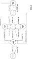
Figure 2 is a block diagram of the operation of the system inFigure 1 . - In
Figure 1 , the reference number 1 generally indicates a system for the quick cooking of non-precooked dry pasta as a whole. The system 1 is a professional tool for quick catering (commonly called "fast") conducted by an operator who supervises and operates the system 1 and then picks up the cooked pasta to separately add the seasoning. The system 1 does not produce the seasoning; this is done separately through the use of external equipment (such as a flame or induction hob). The dry pasta cooked with the system 1 has preferably a thin folder (i.e. thickness). - The system 1 comprises a
single cooking chamber 2 inside of which the cooking water is supplied. - The
cooking chamber 2 is delimited by aside wall 2A and/or twoend walls 2B. Thecooking chamber 2 is, therefore, basically a tank into which the pre-heated cooking water is supplied. The system 1 involves just one cooking step for the dry pasta. - The system 1 for the quick cooking of dry pasta comprises a cooking
water heating device 3 and a drainingunit 4 arranged downstream of thecooking chamber 2. The drainingunit 4 is configured to collect the cooking water and the cooked pasta at the end of the cooking cycle. - Each cooking cycle preferably uses fresh pre-heated cooking water and does not reuse the cooking water from the previous cycle.
- At the start of the new cooking cycle, the dry pasta is inserted directly into the pre-heated cooking water at the inlet temperature Ti, which is already present in the
cooking chamber 2, and which is then heated to a higher operating temperature To than the inlet temperature Ti. At any time before the start of the cooking cycle, therefore, thewalls cooking chamber 2 are at least at the same temperature as the inlet temperature Ti. - The inlet temperature Ti ranges between 80 and 100°C, preferably the inlet temperature Ti is approximately 90°C. The operating temperature To is higher than the inlet temperature Ti. In particular, the operating temperature To is usually higher than 120°C, in particular it is about 140°.
- The
cooking chamber 2 is configured to collect the pasta in the pre-heated cooking water at the inlet temperature Ti that is then further heated to the operating temperature To to cook the pasta. Thecooking chamber 2 is provided with a supply opening 5 for the dry pasta, a supply opening 6 for the pre-heated cooking water from theheating device 3, and a discharge opening 7 for the cooking water and the cooked pasta at the end of the cooking cycle. - A
valve 8 is advantageously arranged in correspondence of the supply opening 5 for the dry pasta, which enables or prevents the dry pasta from being supplied to thecooking chamber 2. Analogously, in correspondence of the discharge opening 7 for the cooking water and the cooked pasta, there is avalve 9 that enables or prevents the cooking water and the cooked pasta from being supplied to the drainingunit 4 below. - According to a possible embodiment, the
valves end walls 2B. In other words, thevalves corresponding end walls 2B. - According to a possible embodiment, in correspondence of the supply opening 5 for the dry pasta, the system 1 comprises, for example, a hopper for supplying the dry pasta to the
cooking chamber 2. - The draining
unit 4 is arranged downstream of thecooking chamber 2 and is configured to collect the cooking water and the cooked pasta supplied through the discharge opening 7 at the end of the cooking cycle. - According to a possible embodiment, the system 1 comprises opening and closing elements, such as doors, in correspondence of the supply opening 5 for the dry pasta and of the draining
unit 4 in order to access the compartment where the pasta is stored (in the case of the supply opening 5) or picked up (in the case of the draining unit 4). - The
draining unit 4 advantageously comprises a draining element (not illustrated), such as a strainer. The strainer is made in such a way as to preserve part of the cooking water that is then used to amalgamate the pasta with the seasoning, using the starch contained in the cooking water. - According to one possible embodiment, the draining element is a container comprising a side wall and a bottom wall. The side wall basically has a lower portion and an upper portion. The upper portion is higher (i.e. has a greater longitudinal extension) than the lower portion. The upper portion comprises a plurality of holes through which the cooking water flows out to drain the pasta. The lower portion and the bottom wall are without holes. The cooking water collected in correspondence of the lower portion is, therefore, collected and then used to amalgamate the pasta with the seasoning using the starch contained in the cooking water.
- As illustrated in
Figure 1 , the system 1 also comprises avapour generation device 10 that supplies water vapour through at least two watervapour supply openings 11 made in thecooking chamber 2 to introduce it into the cooking water. By introducing water vapour, the cooking water is further heated, a forced circulation of the cooking water is established in thecooking chamber 2, and the pasta is stirred in thecooking chamber 2. - The water vapour is preferably supplied to the
cooking chamber 2 under pressure. - At the end of each cooking cycle, the water vapour is removed through a water vapour discharge opening 12, depressurising the
cooking chamber 2 at the same time. In fact, considering that thecooking chamber 2 is a closed tank, as the temperature inside thecooking chamber 2 increases, the pressure inside it also increases. - The system 1 comprises two or more water
vapour supply openings 11 to further increase the forced circulation of the cooking water in thecooking chamber 2 and, thus, to stir the pasta more during cooking. In other words, by introducing water vapour from two or more watervapour supply openings 11, the turbulence in the cooking water is increased. - In correspondence of each water vapour supply opening 11 there is, advantageously, a nozzle (not illustrated) that introduces the vapour into the
cooking chamber 2. - The water
vapour supply openings 11 preferably have an orientation i.e. a relative inclination in relation to thecooking chamber 2 that is different to each other. In other words, the watervapour supply openings 11 are inclined at a different angle to each other in relation to theside wall 2A and/or to theend walls 2B. - Alternatively, at least two water
vapour supply openings 11 have an orientation i.e. a relative inclination in relation to thecooking chamber 2 that is basically the same as each other. In other words, at least two watervapour supply openings 11 are inclined with basically the same inclination angle in relation to theside wall 2A and/or to theend walls 2B. - In addition, the water
vapour supply openings 11 can be actuated independently of each other. Thesupply openings 11 can, therefore, be operated simultaneously or alternately to generate the forced circulation of the cooking water, and, thus, of the pasta, inside thecooking chamber 2. - In particular, if there are nozzles in correspondence of the
supply openings 11, the nozzles have an orientation in relation to theside wall 2A and/or theend walls 2B of thecooking chamber 2 that is different from each other. For example, one of the nozzles introduces water vapour along a direction that is basically perpendicular to theside wall 2A of thecooking chamber 2. While the other nozzle introduces water vapour along the direction basically transverse (e.g. along a tangential direction) to theside wall 2A of thecooking chamber 2. The nozzles can be actuated independently of each other. The nozzles can, therefore, be operated simultaneously or alternately to generate the forced circulation of the cooking water, and, thus, of the pasta, inside thecooking chamber 2. - In the preferred embodiment, illustrated in
Figure 1 , the supply opening 5 for the dry pasta is arranged in correspondence of theupper end wall 2B; while thedischarge opening 7 for the cooking water and the cooked pasta is arranged in correspondence of thelower end wall 2B. On the other hand, the cookingwater supply opening 6, thevapour supply opening 11, and the watervapour discharge opening 12 are arranged in correspondence of theside wall 2A. In particular, the cookingwater supply openings 6, the watervapour supply opening 11, and the watervapour discharge opening 12 are arranged at different levels (i.e. heights). The term height defines the dimension measured parallel to theside wall 2A. - In particular, as illustrated in
Figure 1 , theopenings side wall 2A: the watervapour discharge opening 12 is arranged high up (basically near theupper end surface 2B); the cookingwater supply opening 6 is arranged at a lower level; and then the watervapour supply opening 11 is arranged below that. Since the watervapour supply opening 11 is lower than the pre-heated cookingwater supply opening 6, the water vapour is directly introduced into the cooking water, which is then heated. The water vapour is, therefore, not introduced directly onto the pasta, but rather into the cooking water, in order to avoid direct contact between the pasta being cooked and the water vapour introduced. This creates a combined cooking involving cooking water and water vapour, which is gentler. - The system 1 comprises a plurality of
temperature sensors 13. Thetemperature sensors 13 are arranged both outside thecooking chamber 2 and inside thecooking chamber 2. Thetemperature sensor 13 arranged outside thecooking chamber 2 detects the outside temperature of the room surrounding thecooking chamber 2. - The
temperature sensors 13 arranged in thecooking chamber 2, on the other hand, detect the temperature of the cooking water at different levels (i.e. heights) in thecooking chamber 2 to ensure that the actual inlet temperature Ti corresponds to a set reference inlet temperature Tir and/or that the actual operating temperature To corresponds to a set reference operating temperature Tor. Thetemperature sensors 13 constantly monitor the outside temperature, the inlet temperature Ti, and the operating temperature To, and in thecooking chamber 2, and send the signal to an electronic control unit ECU that processes the signal and adjusts, particularly with a feedback control, the inlet temperature Ti of the cooking water in thecooking chamber 2 and/or the operating temperature To of the cooking water in thecooking chamber 2. The adjustment of the inlet temperature Ti and the operating temperature To can be made independently of each other. - If the electronic control unit ECU detects that the actual inlet temperature Ti is lower than the reference inlet temperature value Tir and/or if the actual operating temperature To is lower than the reference operating temperature value Tor, then it commands the introduction of water vapour into the
cooking chamber 2. - In addition, the electronic control unit ECU determines a compensation value ΔT depending on the external temperature, the inlet temperature Ti, and/or the operating temperature To to be added to or subtracted from the theoretical cooking time T. The theoretical cooking time T is usually set by the control unit ECU depending on the type of pasta selected. The theoretical cooking time T usually ranges between 40s and 70s. Through this compensation it is possible to optimise the cooking cycles in relation to the different types of pasta, environmental conditions, and/or the system 1 states.
- As illustrated in
Figure 1 , the system 1 comprises a plurality of pipes for supplying or discharging cooking water or vapour. In particular, the cooking water is drawn from a water source 14 (e.g. the water mains) via apipe 15. Anode 16 is arranged along thepipe 15, wherein thepipe 15 branches off into apipe 17 that supplies water to theheating device 3 and into apipe 18 that supplies water to thevapour generation device 10. A shut-offvalve 21 is arranged along thepipe 17, which enables or prevents the cooking water to pass to theheating device 3. Apipe 22 starts from theheating device 3 that supplies the pre-heated cooking water to thecooking chamber 2. Apump 23 and a shut-offvalve 24 are arranged along thepipe 22. Depending on how thevalve 24 is controlled, the cooking water's passage to thecooking chamber 2 is either enabled or prevented. When supplying pre-heated cooking water to thecooking chamber 2, thecooking chamber 2valves cooking chamber 2 at the inlet temperature Ti until the operator starts the cooking cycle. In other words, only after the pasta has been introduced into thecooking chamber 2 is the cooking water heated to the operating temperature To for cooking the pasta. - The cooking water is supplied via the
pipe 18 to thevapour generation device 10, in which the cooking water is heated so that it evaporates and generates water vapour. The water vapour is supplied to thecooking chamber 2 via thepipe 25. Along thepipe 25 there is anode 26, wherein thepipe 25 branches off into twopipes pipes cooking chamber 2 at different levels. Along thepipe 27, there is a shut-offvalve 31, which enables or prevents the water vapour's passage. - Similarly, a shut-off
valve 32 is arranged along thepipe 27 that enables or prevents the water vapour's passage. The shut-offvalves valves - As illustrated in
Figure 1 , a discharge pipe 33 starts from the watervapour discharge opening 12. Anode 34 is arranged along the discharge pipe 33, wherein thepipe 35 branches off into apipe 35 that supplies the water vapour to be disposed. Apipe 36 branches off from thenode 34 parallel to thepipe 35. Two shut-offvalves pipes pipe cooking chamber 2 is stopped and then the shut-offvalve 37 and/or 38 is opened (e.g. for just a few seconds) to discharge the water vapour and, thus, to depressurise thecooking chamber 2. Downstream of the shut-offvalves pipes node 41. From thenode 41, apipe 42 branches off and supplies the water vapour to thedischarge unit 4. - The shut-off
valves - In the preferred embodiment, the system 1 also comprises a data entering and displaying interface (not illustrated). The data entering and displaying interface is for example a touch screen with which the operator can select, for example, the system 1 mode (i.e. pre-heating, cooking cycle, descaling cycle, or cleaning cycle that will be described in detail below), the type of pasta chosen, the theoretical cooking time T, the inlet temperature Ti (if different from the pre-set one), etc. It can also display the output information of the system 1, such as the operating temperature To, the actual cooking time T, the cooking step, the type of cycle currently being performed by the system 1, etc.
-
Figure 2 illustrates a plan of the operation of the system 1, by way of example. The system 1 is initially switched off and, thus, none of the elements (e.g. theheating device 3, the watervapour generation device 10, etc.) of the system 1 are supplied with electricity. When the power is switched on, the control unit ECU checks if the plug is plugged in. If this condition is fulfilled (i.e. "True") the re-set procedure is started. During the re-set procedure, thecooking chamber 2 is depressurised and thevalve 9, through which any water in the system 1 is drained, is opened. If the re-set procedure is completed, the system 1 is in standby mode (indicated as "idle"), wherein the watervapour generation device 10 and the cookingwater heating device 3 are not active. The system 1 waits for the input of the operator who, by pressing one of the buttons on the interface, can switch the system 1 to one of the following modes: pre-heating, cooking cycle, descaling cycle, and cleaning cycle. - In the pre-heating mode, the water
vapour generation device 10 and the cookingwater heating device 3 are activated. - The pre-heated cooking water is supplied to the
cooking chamber 2 through thepipe 22, while thevalves cooking chamber 2 and the temperature outside thecooking chamber 2 are constantly monitored. When a drop in the inlet temperature Ti is recorded, water vapour is introduced to bring the water back to the set reference inlet temperature Ti. When the operator selects the start of the cooking cycle, the pasta is introduced into thecooking chamber 2 and the water vapour is introduced to further heat the cooking water inside thecooking chamber 2 up to the operating temperature To. - If the system 1 continues in the pre-heating mode for longer than a threshold value that can be pre-set, the system 1 automatically switches to the re-set procedure mode, after having drained the
cooking chamber 2 through the re-set procedure. - In standby mode, the system 1 automatically checked whether a cleaning cycle needs to be started.
- The cleaning cycle can also be manually set.
- If the result of the check is affirmative (i.e. True), the cleaning cycle is started. At the end of the cleaning cycle, the system 1 returns to standby mode. Alternatively, by pressing the "back" button, for example, the operator can choose to return the system 1 to the re-set procedure. In standby mode, the system automatically checks whether a descaling cycle needs to be started. The descaling cycle can also be manually set. If the result of the check is affirmative (i.e. True), the descaling cycle is started. At the end of the descaling cycle, the system 1 returns to standby mode. Alternatively, by pressing the "back" button, for example, the operator can choose to return the system 1 to the re-set procedure.
- The cooking cycle mode is the operating mode of the system 1 after start-up. The start-up can be controlled via buttons on the interface. The dry pasta is then introduced through the opening of the
valve 8, which is then closed again. The water vapour generated by the watervapour generation device 10 is then introduced into thecooking chamber 2, preferably in a pulse mode, to bring the cooking water to the operating temperature To. At the end, or shortly before the end, of the cooking step (usually after almost a minute of cooking) the flow of water vapour is stopped, after which the shut-offvalve cooking chamber 2. Then thevalve 9 is opened to make the pasta slide into the strainer of thedraining unit 4. The system 1 warns the operator of the draining via a visual signal on the interface or using an acoustic signal. - For example, the operator opens the special door (if present) of the
draining unit 4 and takes out the draining element containing the cooked pasta and part of the cooking water. After this, the system 1 automatically returns to the re-set procedure. - The system 1 described above has multiple advantages. First of all, the system 1 makes it possible to cook the dry pasta (for example Andalini pasta that cooks in four minutes - A4m) in 60 seconds, without needing to pre-cook it, thus achieving a significant reduction in the cooking time, which can be as much as 75%, thus meeting the needs of professional use for fast food catering. The cooking time is also reduced by keeping the cooking water and the
cooking chamber 2 itself at the inlet temperature Ti, so that the system 1 is ready to use at any time. - The combined use of pre-heated cooking water and water vapour makes it possible to cook the pasta using a single cooking step, i.e. without pre-cooking the dry pasta and makes cooking gentler, because the vapour is not in direct contact with the pasta.
- By introducing water vapour through two
different supply openings 11, which are preferably also directed differently from each other, the cooking water is forced to circulate in thecooking chamber 2, so that the cooking water is heated evenly and the pasta is stirred. - The control unit ECU continuously monitors the inlet temperature Ti, the operating temperature To, and the temperature outside the
cooking chamber 2 and, if necessary, intervenes to increase or decrease the inlet temperature Ti and/or the operating temperature To. In addition, the unit ECU increases or reduces the cooking time of the pasta depending on the inlet temperature Ti, the operating temperature To, and the external temperature detected. - The system 1 also makes it possible to maintain the inlet temperature Ti in the
cooking chamber 2 between the introduction of the water and the actual start of the cooking cycle, without the aid of external elements, for example by making a interspace filled with a thermovector fluid in correspondence of theside wall 2A and/or theend walls 2B of thecooking chamber 2. In the system 1, the temperature in thecooking chamber 2 is maintained (especially at the inlet temperature Ti) since the pre-heated cooking water remains at the inlet temperature Ti in thecooking chamber 2 between the introduction of the cooking water and the actual start of the cooking cycle. In addition, the cooking water inlet temperature Ti is continuously monitored and, through the periodic supply of water vapour, the cooking water is always kept at the inlet temperature Ti. The pre-heated cooking water will then be used as cooking water when the operator requests a new cooking cycle. In this case, the cooking water is brought to the operating temperature To by the introduction of additional water vapour. - The draining element of the
draining unit 4 allows the operator to easily pick up the cooked pasta by preserving part of the cooking water that is used to mix it with the seasoning. - Moreover, as the pasta is supplied to the
cooking chamber 2 dry and not pre-cooked, the cooked pasta obtained is of a higher quality. - Therefore, the system 1 makes a quality pasta using gentle cooking (e.g. without direct steam), so that the cooking water can penetrate the dry pasta and an easily digestible pasta is obtained.
- The system 1 guarantees repeatability, i.e. same quality of pasta cooking is attained across different cooking cycles, regardless of the external conditions (external and inlet pasta temperature) and the use/status of the system 1 (i.e. regardless of whether there are sporadic or close cooking cycles).
- Moreover, the system 1 guarantees uniformity, i.e. the same quality of cooking is attained within a single portion of cooked pasta.
Claims (15)
- A system (1) for quick cooking of non-precooked dry pasta comprising:a heating device (3) to pre-heat the pasta cooking water;a cooking chamber (2), which is configured to cook the pasta in the cooking water; the cooking chamber (2) is provided with a supply opening (5) to supply the non-precooked dry pasta, a supply opening (6) to supply the pre-heated cooking water from the heating device (3) and a discharge opening (7) to discharge the cooking water and the cooked pasta at the end of each cooking cycle;a draining unit (4), which is arranged downstream of the cooking chamber (2) and is configured to receive the cooking water and the cooked pasta supplied through the discharge opening (7) at the end of the cooking cycle; anda water vapour generating device (10);the system (1) is characterised in that the water vapour generating device (10) comprises two or more water vapour supply openings (11) made in the cooking chamber (2), so as to heat the cooking water, establish a forced circulation of the cooking water in the cooking chamber (2) and stir the pasta.
- The system (1) according to claim 1, wherein at least two water vapour supply openings (11) are oriented, in relation to the cooking chamber (2), which is equal to one another.
- The system (1) according to claim 1, wherein the water vapour supply openings (11) are oriented, in relation to the cooking chamber (2), which is different to one another.
- The system (1) according to any of the claims from 1 to 3, wherein the water vapour supply openings (11) are actuated independently from one another.
- The system (1) according to one of the claims from 1 to 4, wherein the water vapour supply opening (11) is arranged at a lower level than the pre-heated cooking water supply opening (6), so as to directly introduce the water vapour into the cooking water.
- The system (1) according to one of the claims from 1 to 5, wherein the water vapour is supplied under pressure to the cooking chamber (2).
- The system (1) according to one of the claims from 1 to 6, wherein the cooking chamber (2) comprises a water vapour discharge opening (12) to remove the water vapour and to depressurize the cooking chamber (2) at the end of the cooking cycle.
- The system (1) according to one of the claims from 1 to 7 and comprising a hopper to supply the dry pasta to the cooking chamber (2).
- The system (1) according to one of the claims from 1 to 8 and comprising a data entering and displaying interface.
- The system (1) according to one of the claims from 1 to 9 and comprising a plurality of temperature sensors designed to detect an external temperature, a cooking water inlet temperature (Ti) and a cooking water operating temperature (To) so as to adjust, preferably with a feedback control, the cooking water inlet temperature (Ti) in the cooking chamber (2) and/or the cooking water operating temperature (To) in the cooking chamber (2).
- The system (1) according to one of the claims from 1 to 10, wherein the draining unit (4) comprises a draining element provided with a side wall and a bottom wall; ad wherein the side wall has an upper portion comprising a plurality of holes, through which the cooking water flows out, and a lower portion without holes in order to collect part of the cooking water.
- A method for quick cooking of non-precooked dry pasta with a cooking system (1) provided with a cooking chamber (2); the method comprising the steps of:supplying the pre-heated cooking water to the cooking chamber (2) at an inlet temperature (Ti);starting the cooking cycle and heating the cooking water collected in the cooking chamber (2) at an operating temperature (To), after having introduced the pasta into the cooking chamber (2), through the introduction of water vapour;measuring an external temperature, the inlet temperature (Ti) and the operating temperature (To) of the cooking water collected in the cooking chamber (2) by means of temperature sensors (13);comparing the measured inlet temperature (Ti) with a reference inlet temperature value (Tir) and/or the measured operating temperature (To) with a reference operating temperature value (Tor);introducing water vapour into the cooking chamber (2), if the actual inlet temperature (Ti) is lower than the reference inlet temperature value (Tir) and/or if the actual operating temperature (To) is lower than the reference operating temperature value (Tor);determining a compensation value (ΔT) as a function of the external temperature, of the inlet temperature (Ti) and/or of the operating temperature (To) to be added to or subtracted from the theoretical cooking time (T);removing the water vapour and depressurizing the cooking chamber (2) at the end of the cooking cycle; andpicking up the cooked pasta from a draining unit (4).
- The method according to claim 12, wherein the cooking water supplied to the cooking chamber (2) has the inlet temperature (Ti) ranging from 80 to 100°C, preferably equal to 90°C.
- The method according to claim 12 or 13, wherein the operating temperature (To) is greater than 120°C, in particular substantially equal to approximately 140°.
- The method according to one of the claims from 12 to 14 and comprising the further step of keeping the cooking water in the cooking chamber (2) at the inlet temperature (Ti) until the introduction of the pasta into the cooking chamber (2).
Applications Claiming Priority (1)
| Application Number | Priority Date | Filing Date | Title |
|---|---|---|---|
| IT102019000001407A IT201900001407A1 (en) | 2019-01-31 | 2019-01-31 | SYSTEM FOR QUICK COOKING OF NON-PRE-COOKED DRY PASTA AND RELATIVE COOKING METHOD |
Publications (2)
| Publication Number | Publication Date |
|---|---|
| EP3689197A1 EP3689197A1 (en) | 2020-08-05 |
| EP3689197B1 true EP3689197B1 (en) | 2021-11-03 |
Family
ID=66380005
Family Applications (1)
| Application Number | Title | Priority Date | Filing Date |
|---|---|---|---|
| EP20154996.1A Active EP3689197B1 (en) | 2019-01-31 | 2020-01-31 | A system for the quick cooking of a non-precooked dry pasta and related cooking method |
Country Status (2)
| Country | Link |
|---|---|
| EP (1) | EP3689197B1 (en) |
| IT (1) | IT201900001407A1 (en) |
Family Cites Families (3)
| Publication number | Priority date | Publication date | Assignee | Title |
|---|---|---|---|---|
| EP0140987B1 (en) * | 1983-10-03 | 1987-12-23 | Interimport F. Caceffo GmbH | Apparatus for cooking food |
| US7001637B2 (en) * | 2001-02-16 | 2006-02-21 | Romar Llc | Cooking machine |
| ITMI20011410A1 (en) * | 2001-07-03 | 2003-01-03 | Trombetta Ennio | AUTOMATIC PASTA COOKER FOR SPAGHETTERIE AND SIMILAR RESTAURANTS |
-
2019
- 2019-01-31 IT IT102019000001407A patent/IT201900001407A1/en unknown
-
2020
- 2020-01-31 EP EP20154996.1A patent/EP3689197B1/en active Active
Also Published As
| Publication number | Publication date |
|---|---|
| IT201900001407A1 (en) | 2020-07-31 |
| EP3689197A1 (en) | 2020-08-05 |
Similar Documents
| Publication | Publication Date | Title |
|---|---|---|
| US11426027B2 (en) | Air fryer with steaming function and method for controlling air fryer with steaming function | |
| EP2710303B1 (en) | Combination cooking oven with operator friendly humidity control | |
| US6909071B2 (en) | Overheated steam oven and method of controlling the same | |
| US20050051160A1 (en) | Steam oven | |
| US20240172778A1 (en) | Cooking appliance for cooking food, cooking method, control unit, and computer program product | |
| CN111035233B (en) | Intelligent steaming and baking integrated equipment | |
| CN100436948C (en) | Control method of microwave oven | |
| CN109527980B (en) | Steaming and baking combined machine | |
| EP3689197A1 (en) | A system for the quick cooking of a non-precooked dry pasta and related cooking method | |
| CN100412447C (en) | Control method of microwave oven | |
| JP4254521B2 (en) | Cooking device operation control method and cooking device | |
| CN113812863A (en) | Control method, device and system of steaming and baking oven and steaming and baking oven | |
| CN110226887A (en) | Food cooking machine and its control method | |
| JP4222978B2 (en) | Cooker | |
| KR100526210B1 (en) | Steam cooking apparatus | |
| JP2009284772A (en) | Cooking method in cooker | |
| JP2007198697A (en) | Cooking method | |
| JP4678306B2 (en) | Cooking device operation control method | |
| KR20140107841A (en) | A steam oven and a control method thereof | |
| JP2010210120A (en) | Heating cooker | |
| JP2007321993A (en) | Cooker | |
| KR100531758B1 (en) | A self-cleaning of cooker | |
| KR19990005367A (en) | Control Method of Electric Pressure Cooker | |
| JPH0998889A (en) | Heating/heat retaining device | |
| KR20080048571A (en) | Cooking appliance |
Legal Events
| Date | Code | Title | Description |
|---|---|---|---|
| PUAI | Public reference made under article 153(3) epc to a published international application that has entered the european phase |
Free format text: ORIGINAL CODE: 0009012 |
|
| STAA | Information on the status of an ep patent application or granted ep patent |
Free format text: STATUS: THE APPLICATION HAS BEEN PUBLISHED |
|
| AK | Designated contracting states |
Kind code of ref document: A1 Designated state(s): AL AT BE BG CH CY CZ DE DK EE ES FI FR GB GR HR HU IE IS IT LI LT LU LV MC MK MT NL NO PL PT RO RS SE SI SK SM TR |
|
| AX | Request for extension of the european patent |
Extension state: BA ME |
|
| STAA | Information on the status of an ep patent application or granted ep patent |
Free format text: STATUS: REQUEST FOR EXAMINATION WAS MADE |
|
| 17P | Request for examination filed |
Effective date: 20201215 |
|
| RBV | Designated contracting states (corrected) |
Designated state(s): AL AT BE BG CH CY CZ DE DK EE ES FI FR GB GR HR HU IE IS IT LI LT LU LV MC MK MT NL NO PL PT RO RS SE SI SK SM TR |
|
| GRAP | Despatch of communication of intention to grant a patent |
Free format text: ORIGINAL CODE: EPIDOSNIGR1 |
|
| STAA | Information on the status of an ep patent application or granted ep patent |
Free format text: STATUS: GRANT OF PATENT IS INTENDED |
|
| RIC1 | Information provided on ipc code assigned before grant |
Ipc: A47J 27/14 20060101AFI20210430BHEP |
|
| INTG | Intention to grant announced |
Effective date: 20210528 |
|
| GRAS | Grant fee paid |
Free format text: ORIGINAL CODE: EPIDOSNIGR3 |
|
| GRAA | (expected) grant |
Free format text: ORIGINAL CODE: 0009210 |
|
| STAA | Information on the status of an ep patent application or granted ep patent |
Free format text: STATUS: THE PATENT HAS BEEN GRANTED |
|
| AK | Designated contracting states |
Kind code of ref document: B1 Designated state(s): AL AT BE BG CH CY CZ DE DK EE ES FI FR GB GR HR HU IE IS IT LI LT LU LV MC MK MT NL NO PL PT RO RS SE SI SK SM TR |
|
| REG | Reference to a national code |
Ref country code: GB Ref legal event code: FG4D |
|
| REG | Reference to a national code |
Ref country code: AT Ref legal event code: REF Ref document number: 1443202 Country of ref document: AT Kind code of ref document: T Effective date: 20211115 Ref country code: CH Ref legal event code: EP |
|
| REG | Reference to a national code |
Ref country code: DE Ref legal event code: R096 Ref document number: 602020000870 Country of ref document: DE |
|
| REG | Reference to a national code |
Ref country code: IE Ref legal event code: FG4D |
|
| REG | Reference to a national code |
Ref country code: LT Ref legal event code: MG9D |
|
| REG | Reference to a national code |
Ref country code: NL Ref legal event code: MP Effective date: 20211103 |
|
| REG | Reference to a national code |
Ref country code: AT Ref legal event code: MK05 Ref document number: 1443202 Country of ref document: AT Kind code of ref document: T Effective date: 20211103 |
|
| PG25 | Lapsed in a contracting state [announced via postgrant information from national office to epo] |
Ref country code: RS Free format text: LAPSE BECAUSE OF FAILURE TO SUBMIT A TRANSLATION OF THE DESCRIPTION OR TO PAY THE FEE WITHIN THE PRESCRIBED TIME-LIMIT Effective date: 20211103 Ref country code: LT Free format text: LAPSE BECAUSE OF FAILURE TO SUBMIT A TRANSLATION OF THE DESCRIPTION OR TO PAY THE FEE WITHIN THE PRESCRIBED TIME-LIMIT Effective date: 20211103 Ref country code: FI Free format text: LAPSE BECAUSE OF FAILURE TO SUBMIT A TRANSLATION OF THE DESCRIPTION OR TO PAY THE FEE WITHIN THE PRESCRIBED TIME-LIMIT Effective date: 20211103 Ref country code: BG Free format text: LAPSE BECAUSE OF FAILURE TO SUBMIT A TRANSLATION OF THE DESCRIPTION OR TO PAY THE FEE WITHIN THE PRESCRIBED TIME-LIMIT Effective date: 20220203 Ref country code: AT Free format text: LAPSE BECAUSE OF FAILURE TO SUBMIT A TRANSLATION OF THE DESCRIPTION OR TO PAY THE FEE WITHIN THE PRESCRIBED TIME-LIMIT Effective date: 20211103 |
|
| PG25 | Lapsed in a contracting state [announced via postgrant information from national office to epo] |
Ref country code: IS Free format text: LAPSE BECAUSE OF FAILURE TO SUBMIT A TRANSLATION OF THE DESCRIPTION OR TO PAY THE FEE WITHIN THE PRESCRIBED TIME-LIMIT Effective date: 20220303 Ref country code: SE Free format text: LAPSE BECAUSE OF FAILURE TO SUBMIT A TRANSLATION OF THE DESCRIPTION OR TO PAY THE FEE WITHIN THE PRESCRIBED TIME-LIMIT Effective date: 20211103 Ref country code: PT Free format text: LAPSE BECAUSE OF FAILURE TO SUBMIT A TRANSLATION OF THE DESCRIPTION OR TO PAY THE FEE WITHIN THE PRESCRIBED TIME-LIMIT Effective date: 20220303 Ref country code: PL Free format text: LAPSE BECAUSE OF FAILURE TO SUBMIT A TRANSLATION OF THE DESCRIPTION OR TO PAY THE FEE WITHIN THE PRESCRIBED TIME-LIMIT Effective date: 20211103 Ref country code: NO Free format text: LAPSE BECAUSE OF FAILURE TO SUBMIT A TRANSLATION OF THE DESCRIPTION OR TO PAY THE FEE WITHIN THE PRESCRIBED TIME-LIMIT Effective date: 20220203 Ref country code: NL Free format text: LAPSE BECAUSE OF FAILURE TO SUBMIT A TRANSLATION OF THE DESCRIPTION OR TO PAY THE FEE WITHIN THE PRESCRIBED TIME-LIMIT Effective date: 20211103 Ref country code: LV Free format text: LAPSE BECAUSE OF FAILURE TO SUBMIT A TRANSLATION OF THE DESCRIPTION OR TO PAY THE FEE WITHIN THE PRESCRIBED TIME-LIMIT Effective date: 20211103 Ref country code: HR Free format text: LAPSE BECAUSE OF FAILURE TO SUBMIT A TRANSLATION OF THE DESCRIPTION OR TO PAY THE FEE WITHIN THE PRESCRIBED TIME-LIMIT Effective date: 20211103 Ref country code: GR Free format text: LAPSE BECAUSE OF FAILURE TO SUBMIT A TRANSLATION OF THE DESCRIPTION OR TO PAY THE FEE WITHIN THE PRESCRIBED TIME-LIMIT Effective date: 20220204 Ref country code: ES Free format text: LAPSE BECAUSE OF FAILURE TO SUBMIT A TRANSLATION OF THE DESCRIPTION OR TO PAY THE FEE WITHIN THE PRESCRIBED TIME-LIMIT Effective date: 20211103 |
|
| PG25 | Lapsed in a contracting state [announced via postgrant information from national office to epo] |
Ref country code: SM Free format text: LAPSE BECAUSE OF FAILURE TO SUBMIT A TRANSLATION OF THE DESCRIPTION OR TO PAY THE FEE WITHIN THE PRESCRIBED TIME-LIMIT Effective date: 20211103 Ref country code: SK Free format text: LAPSE BECAUSE OF FAILURE TO SUBMIT A TRANSLATION OF THE DESCRIPTION OR TO PAY THE FEE WITHIN THE PRESCRIBED TIME-LIMIT Effective date: 20211103 Ref country code: RO Free format text: LAPSE BECAUSE OF FAILURE TO SUBMIT A TRANSLATION OF THE DESCRIPTION OR TO PAY THE FEE WITHIN THE PRESCRIBED TIME-LIMIT Effective date: 20211103 Ref country code: EE Free format text: LAPSE BECAUSE OF FAILURE TO SUBMIT A TRANSLATION OF THE DESCRIPTION OR TO PAY THE FEE WITHIN THE PRESCRIBED TIME-LIMIT Effective date: 20211103 Ref country code: DK Free format text: LAPSE BECAUSE OF FAILURE TO SUBMIT A TRANSLATION OF THE DESCRIPTION OR TO PAY THE FEE WITHIN THE PRESCRIBED TIME-LIMIT Effective date: 20211103 Ref country code: CZ Free format text: LAPSE BECAUSE OF FAILURE TO SUBMIT A TRANSLATION OF THE DESCRIPTION OR TO PAY THE FEE WITHIN THE PRESCRIBED TIME-LIMIT Effective date: 20211103 |
|
| REG | Reference to a national code |
Ref country code: DE Ref legal event code: R119 Ref document number: 602020000870 Country of ref document: DE |
|
| PG25 | Lapsed in a contracting state [announced via postgrant information from national office to epo] |
Ref country code: MC Free format text: LAPSE BECAUSE OF FAILURE TO SUBMIT A TRANSLATION OF THE DESCRIPTION OR TO PAY THE FEE WITHIN THE PRESCRIBED TIME-LIMIT Effective date: 20211103 |
|
| PLBE | No opposition filed within time limit |
Free format text: ORIGINAL CODE: 0009261 |
|
| STAA | Information on the status of an ep patent application or granted ep patent |
Free format text: STATUS: NO OPPOSITION FILED WITHIN TIME LIMIT |
|
| RAP4 | Party data changed (patent owner data changed or rights of a patent transferred) |
Owner name: PASTIFICIO ANDALINI S.P.A. |
|
| REG | Reference to a national code |
Ref country code: BE Ref legal event code: MM Effective date: 20220131 |
|
| 26N | No opposition filed |
Effective date: 20220804 |
|
| PG25 | Lapsed in a contracting state [announced via postgrant information from national office to epo] |
Ref country code: LU Free format text: LAPSE BECAUSE OF NON-PAYMENT OF DUE FEES Effective date: 20220131 Ref country code: DE Free format text: LAPSE BECAUSE OF NON-PAYMENT OF DUE FEES Effective date: 20220802 Ref country code: AL Free format text: LAPSE BECAUSE OF FAILURE TO SUBMIT A TRANSLATION OF THE DESCRIPTION OR TO PAY THE FEE WITHIN THE PRESCRIBED TIME-LIMIT Effective date: 20211103 |
|
| PG25 | Lapsed in a contracting state [announced via postgrant information from national office to epo] |
Ref country code: SI Free format text: LAPSE BECAUSE OF FAILURE TO SUBMIT A TRANSLATION OF THE DESCRIPTION OR TO PAY THE FEE WITHIN THE PRESCRIBED TIME-LIMIT Effective date: 20211103 Ref country code: BE Free format text: LAPSE BECAUSE OF NON-PAYMENT OF DUE FEES Effective date: 20220131 |
|
| PG25 | Lapsed in a contracting state [announced via postgrant information from national office to epo] |
Ref country code: IE Free format text: LAPSE BECAUSE OF NON-PAYMENT OF DUE FEES Effective date: 20220131 |
|
| REG | Reference to a national code |
Ref country code: CH Ref legal event code: PL |
|
| PG25 | Lapsed in a contracting state [announced via postgrant information from national office to epo] |
Ref country code: LI Free format text: LAPSE BECAUSE OF NON-PAYMENT OF DUE FEES Effective date: 20230131 Ref country code: CH Free format text: LAPSE BECAUSE OF NON-PAYMENT OF DUE FEES Effective date: 20230131 |
|
| PG25 | Lapsed in a contracting state [announced via postgrant information from national office to epo] |
Ref country code: MK Free format text: LAPSE BECAUSE OF FAILURE TO SUBMIT A TRANSLATION OF THE DESCRIPTION OR TO PAY THE FEE WITHIN THE PRESCRIBED TIME-LIMIT Effective date: 20211103 Ref country code: CY Free format text: LAPSE BECAUSE OF FAILURE TO SUBMIT A TRANSLATION OF THE DESCRIPTION OR TO PAY THE FEE WITHIN THE PRESCRIBED TIME-LIMIT Effective date: 20211103 |
|
| PG25 | Lapsed in a contracting state [announced via postgrant information from national office to epo] |
Ref country code: HU Free format text: LAPSE BECAUSE OF FAILURE TO SUBMIT A TRANSLATION OF THE DESCRIPTION OR TO PAY THE FEE WITHIN THE PRESCRIBED TIME-LIMIT; INVALID AB INITIO Effective date: 20200131 |
|
| PG25 | Lapsed in a contracting state [announced via postgrant information from national office to epo] |
Ref country code: TR Free format text: LAPSE BECAUSE OF FAILURE TO SUBMIT A TRANSLATION OF THE DESCRIPTION OR TO PAY THE FEE WITHIN THE PRESCRIBED TIME-LIMIT Effective date: 20211103 |
|
| PG25 | Lapsed in a contracting state [announced via postgrant information from national office to epo] |
Ref country code: MT Free format text: LAPSE BECAUSE OF FAILURE TO SUBMIT A TRANSLATION OF THE DESCRIPTION OR TO PAY THE FEE WITHIN THE PRESCRIBED TIME-LIMIT Effective date: 20211103 |
|
| PGFP | Annual fee paid to national office [announced via postgrant information from national office to epo] |
Ref country code: GB Payment date: 20260126 Year of fee payment: 7 |
|
| PGFP | Annual fee paid to national office [announced via postgrant information from national office to epo] |
Ref country code: IT Payment date: 20260105 Year of fee payment: 7 |
|
| PGFP | Annual fee paid to national office [announced via postgrant information from national office to epo] |
Ref country code: FR Payment date: 20260126 Year of fee payment: 7 |