EP3688485B1 - Methods and systems for filtering of acoustic clutter and random noise - Google Patents
Methods and systems for filtering of acoustic clutter and random noise Download PDFInfo
- Publication number
- EP3688485B1 EP3688485B1 EP18778449.1A EP18778449A EP3688485B1 EP 3688485 B1 EP3688485 B1 EP 3688485B1 EP 18778449 A EP18778449 A EP 18778449A EP 3688485 B1 EP3688485 B1 EP 3688485B1
- Authority
- EP
- European Patent Office
- Prior art keywords
- ultrasound
- channel data
- noise
- predictive error
- data
- Prior art date
- Legal status (The legal status is an assumption and is not a legal conclusion. Google has not performed a legal analysis and makes no representation as to the accuracy of the status listed.)
- Active
Links
Images


Classifications
-
- A—HUMAN NECESSITIES
- A61—MEDICAL OR VETERINARY SCIENCE; HYGIENE
- A61B—DIAGNOSIS; SURGERY; IDENTIFICATION
- A61B8/00—Diagnosis using ultrasonic, sonic or infrasonic waves
- A61B8/52—Devices using data or image processing specially adapted for diagnosis using ultrasonic, sonic or infrasonic waves
- A61B8/5269—Devices using data or image processing specially adapted for diagnosis using ultrasonic, sonic or infrasonic waves involving detection or reduction of artifacts
-
- G—PHYSICS
- G01—MEASURING; TESTING
- G01S—RADIO DIRECTION-FINDING; RADIO NAVIGATION; DETERMINING DISTANCE OR VELOCITY BY USE OF RADIO WAVES; LOCATING OR PRESENCE-DETECTING BY USE OF THE REFLECTION OR RERADIATION OF RADIO WAVES; ANALOGOUS ARRANGEMENTS USING OTHER WAVES
- G01S15/00—Systems using the reflection or reradiation of acoustic waves, e.g. sonar systems
- G01S15/88—Sonar systems specially adapted for specific applications
- G01S15/89—Sonar systems specially adapted for specific applications for mapping or imaging
- G01S15/8906—Short-range imaging systems; Acoustic microscope systems using pulse-echo techniques
- G01S15/8909—Short-range imaging systems; Acoustic microscope systems using pulse-echo techniques using a static transducer configuration
- G01S15/8915—Short-range imaging systems; Acoustic microscope systems using pulse-echo techniques using a static transducer configuration using a transducer array
-
- G—PHYSICS
- G01—MEASURING; TESTING
- G01S—RADIO DIRECTION-FINDING; RADIO NAVIGATION; DETERMINING DISTANCE OR VELOCITY BY USE OF RADIO WAVES; LOCATING OR PRESENCE-DETECTING BY USE OF THE REFLECTION OR RERADIATION OF RADIO WAVES; ANALOGOUS ARRANGEMENTS USING OTHER WAVES
- G01S7/00—Details of systems according to groups G01S13/00, G01S15/00, G01S17/00
- G01S7/52—Details of systems according to groups G01S13/00, G01S15/00, G01S17/00 of systems according to group G01S15/00
- G01S7/52017—Details of systems according to groups G01S13/00, G01S15/00, G01S17/00 of systems according to group G01S15/00 particularly adapted to short-range imaging
- G01S7/52046—Techniques for image enhancement involving transmitter or receiver
-
- G—PHYSICS
- G01—MEASURING; TESTING
- G01S—RADIO DIRECTION-FINDING; RADIO NAVIGATION; DETERMINING DISTANCE OR VELOCITY BY USE OF RADIO WAVES; LOCATING OR PRESENCE-DETECTING BY USE OF THE REFLECTION OR RERADIATION OF RADIO WAVES; ANALOGOUS ARRANGEMENTS USING OTHER WAVES
- G01S7/00—Details of systems according to groups G01S13/00, G01S15/00, G01S17/00
- G01S7/52—Details of systems according to groups G01S13/00, G01S15/00, G01S17/00 of systems according to group G01S15/00
- G01S7/52017—Details of systems according to groups G01S13/00, G01S15/00, G01S17/00 of systems according to group G01S15/00 particularly adapted to short-range imaging
- G01S7/52077—Details of systems according to groups G01S13/00, G01S15/00, G01S17/00 of systems according to group G01S15/00 particularly adapted to short-range imaging with means for elimination of unwanted signals, e.g. noise or interference
-
- A—HUMAN NECESSITIES
- A61—MEDICAL OR VETERINARY SCIENCE; HYGIENE
- A61B—DIAGNOSIS; SURGERY; IDENTIFICATION
- A61B8/00—Diagnosis using ultrasonic, sonic or infrasonic waves
- A61B8/08—Clinical applications
- A61B8/0883—Clinical applications for diagnosis of the heart
Definitions
- This application is directed to autoregressive-moving average (ARMA) spatial filtering. Specifically, this application is directed to ARMA spatial filtering of ultrasound channel data.
- ARMA autoregressive-moving average
- Adaptive weighting techniques such as the coherence factor (CF), the generalized coherence factor (GCF), the phase coherence factor (PCF) and the short-lag spatial coherence (SLSC) all require access to per-channel data to compute a weighting mask to be multiplied to the image.
- apodization-based adaptive weighting methods such as the dual apodization with cross-correlation (DAX) and its variants, weighting masks can be computed without having access to the per-channel data and hence, hardware implementation of these methods may be slightly easier.
- all adaptive weighting methods operate by weighting down the conventional image with a weighting mask. This may lead to problems such as reduced image brightness, removal of anatomical detail, and increased speckle variance.
- Adaptive beamforming techniques such as the minimum variance (MV) beamforming typically involve adaptively calculating the complex apodization values from the channel data such that only mainlobe signals are passed and off-axis signals are rejected.
- MV beamforming is developed mainly for spatial resolution improvement.
- MV beamforming is not effective in suppressing reverberation clutter, which is often correlated with the mainlobe signals.
- reverberation clutter is the dominant source of image quality degradation in vivo.
- MV beamforming is highly sensitive to phase aberration, element directivity, and signal-to-noise ratio. MV beamforming is also known to produce artifacts in speckle.
- J.A. JENSEN "Estimation of pulses in ultrasound B-scan images", IEEE Transactions on Medical Imaging, vol. 10, no. 2, June 1991, pages 164-172, XP055524431 , discloses to use an autoregressive-moving-average (ARMA) model for estimating an ultrasound imaging pulse based on a prediction error method, even in the presence of noise.
- ARMA autoregressive-moving-average
- the systems, methods, and/or apparatuses described herein may improve image contrast with a spatial filtering technique based on autoregressive-moving average (ARMA) model.
- this technique adaptively computes a spatial predictive error filter (PEF) from channel data (a previous unknown from ARMA) and then estimates and subtracts an additive noise sequence that contains contributions from off-axis clutter, reverberation clutter, and/or random noise.
- PEF spatial predictive error filter
- This technique may filter out undesirable signals that contribute to reduced image contrast directly from the ultrasound channel data.
- noise may be treated as a sequence of random innovations instead of an additive process.
- a prediction error filter may be computed from Eigen decomposition of a covariance matrix of noisy channel data.
- the PEF may be applied to the noisy channel data to estimate a noise sequence (e.g. any data not modeled by the RF signals).
- the estimated noise sequence may be subtracted from the original channel data.
- the remaining signal may be "clean" data that may be used to generate an ultrasound image which may have improved contrast compared to the original channel data.
- the ARMA process described may be repeated one or more times on the resulting clean data, which may further improve the resulting image.
- a method includes acquiring ultrasound channel data, generating a predictive error filter with an autoregressive moving average model, estimating, with the predictive error filter, noise in the ultrasound channel data, and subtracting the noise from the ultrasound channel data to obtain clean channel data, wherein the generating step, estimating step and subtracting step are performed in a time-space domain.
- Estimating the predictive error filter with the autoregressive moving average model may include generating a multi-order model of the predictive error filter, converting the multi-order model and the ultrasound channel data to matrix form, solving an eigenvalue problem for the predictive error filter, wherein the eigenvalue problem comprises a correlation matrix of a noisy sequence times the predictive error matrix equal to a variance of noise times the predictive error matrix, wherein a solution of the eigenvalue problem for the predictive error filter is an eigenvector corresponding to a minimum eigenvalue of the correlation matrix of the noisy sequence.
- Estimating the noise in the ultrasound channel data may include deconvolving the predictive error filter and the noisy sequence.
- an ultrasound imaging system includes an ultrasound transducer array configured to transmit and receive ultrasound signals, at least one channel operatively coupled to the ultrasound transducer configured to transmit channel data based, at least in part, on the received ultrasound signals, and a signal processor operatively coupled to the at least one channel, wherein the signal processor is configured to acquire the channel data from the at least one channel, generate a predictive error filter with an autoregressive moving average model, estimate, with the predictive error filter, noise in the channel data, and subtract the noise from the channel data to obtain clean channel data, wherein the generating step, estimating step and subtracting step are performed in a time-space domain.
- a method includes acquiring beamsum data, the beamsum data responsive to a plurality of ultrasound transmit events in a plurality of directions, generating a predictive error filter with an autoregressive moving average model, estimating, with the predictive error filter, noise in the beamsum data, and subtracting the noise from the beamsum data to generate clean data, wherein the generating step, estimating step and subtracting step are performed in a time-space domain.
- a spatial filtering technique based on an ARMA model which may suppress random noise, acoustic clutter, and/or reverberation clutter to enhance image contrast.
- This technique adaptively computes a spatial PEF from ultrasound channel data, and then estimates and subtracts the estimated noise sequence that contains contributions from off-axis clutter, reverberation clutter and/or random noise.
- the ARMA filtering technique (or simply ARMA method) described herein is distinct from the adaptive weighting and adaptive beamforming techniques described in the background of the disclosure.
- the ARMA filtering technique does not use weighting masks for pixel-by-pixel weighting of the original image, and the ARMA filtering technique does not adaptively compute the complex apodization values to form an image. Rather, the ARMA filtering technique filters out undesirable signals that may contribute to reduced image contrast directly from ultrasound channel data.
- the ARMA filtering technique described herein allows signals received from a given direction, which may appear as "linear events" immersed in noise in the time-space (T-X) domain (e.g., aperture domain), may be properly represented by means of an ARMA model.
- the noise is treated as a sequence of random innovations instead of an additive process.
- ARMA modelling of ultrasound channel radio frequency (RF) signals may result in an eigenvalue problem in which a PEF may be computed from Eigen-decomposition of a covariance matrix of the original, noisy channel data.
- the computed PEF may be applied to the noisy channel data to estimate a colored (e.g., non-white noise) noise sequence from which an additive noise sequence is estimated.
- the additive noise sequence may include all the signals that are not modelled by the ARMA model, for example, random noise, off-axis clutter, and/or reverberation clutter.
- the estimated additive noise sequence may be subtracted from the original, noisy channel data to yield "clean" data.
- the clean data may be used to form an ultrasound image.
- the clean data may be used as an input into an iterative ARMA model. That is, the ARMA filtering technique described may be performed multiple times to yield clean data.
- An ultrasound imaging system capable of performing the ARMA filtering technique according principles of the current disclosure includes an ultrasound transducer array configured to transmit and receive ultrasound signals and at least one channel operatively coupled to the ultrasound transducer configured to transmit channel data based, at least in part, on the receive ultrasound signals.
- the ultrasound imaging system further includes a signal processor operatively coupled to the channel.
- the signal processor is configured to acquire the at least one channel data from the channel, generate a PEF with an ARMA model, estimate, with the PEF, noise in the channel data, and subtract the noise from the ultrasound data to obtain clean channel data, wherein the generating step, estimating step and subtracting step are performed in a time-space domain.
- an ultrasound imaging system 10 constructed in accordance with the principles of the present disclosure is shown in block diagram form.
- an ultrasound probe 12 includes a transducer array 14 for transmitting ultrasonic waves and receiving echo information.
- transducer arrays are well known in the art, e.g., linear arrays, convex arrays or phased arrays.
- the transducer array 14, for example, can include a two dimensional array (as shown) of transducer elements capable of scanning in both elevation and azimuth dimensions for 2D and/or 3D imaging.
- the transducer elements of transducer array 14 may be coupled via channels 15 to a microbeamformer 16 in the probe 12 in some embodiments.
- a separate channel may be provided for each transducer element of the transducer array 14 or for each patch of transducer elements. However, for clarity of the diagram, only one line is illustrated for the channels 15 in FIG. 1 .
- the microbeamformer 16 may control transmission and reception of signals by the transducer elements in the array.
- the microbeamformer 16 is coupled by the probe cable to a transmit/receive (T/R) switch 18, which switches between transmission and reception and protects the main beamformer 22 from high energy transmit signals.
- T/R switch 18 and other elements in the system can be included in the transducer probe rather than in a separate ultrasound system base.
- the transmission of ultrasonic beams from the transducer array 14 under control of the microbeamformer 16 is directed by the transmit controller 20 coupled to the T/R switch 18 and the beamformer 22, which receives input from the user's operation of the user interface or control panel 24.
- One of the functions controlled by the transmit controller 20 is the direction in which beams are steered. Beams may be steered straight ahead from (orthogonal to) the transducer array, or at different angles for a wider field of view.
- the partially beamformed signals produced by the microbeamformer 16 are coupled to a main beamformer 22 where partially beamformed signals from individual patches of transducer elements are combined into a fully beamformed signal.
- the microbeamformer 16 is omitted.
- the transmit controller 20 may control the transducer array 14 directly through the T/R switch 18. Data from the transducer array 14 elements may be transmitted via channels 15 to the main beamformer 22.
- the beamformed signals are coupled to a signal processor 26.
- the signal processor 26 can process the received echo signals in various ways, such as bandpass filtering, decimation, I and Q component separation, and harmonic signal separation.
- the signal processor 26 may also perform additional signal enhancement such as speckle reduction, signal compounding, and noise elimination.
- the signal processor 26 may be implemented in hardware (e.g., Application Specific Integrated Circuit (ASIC)), software, or a combination thereof.
- ASIC Application Specific Integrated Circuit
- the signal processor 26 may receive ultrasound signals from the channels 15 prior to beamforming by beamformer 22.
- the signal processor 26 may apply the ARMA filtering technique described above to the signals from the channels 15 (e.g., channel data).
- the beamformer 22 may provide appropriate delays and/or geometrical alignment to each channel 15, and signal processing may be performed by the signal processor 26 prior to summing of the channel signals.
- the signal processor 26 may perform the ARMA filtering technique on the channel data and receive commands from the beamformer 22 for summing of the channel signals.
- the signal processor 26 may apply any desired and/or required summations prior to providing the signals to the B-mode processor 28.
- beamformer 22 may be implemented as two units, one for providing appropriate delays and/or geometrical alignment and another unit may be included for providing summing and/or other combining of channel data if necessary.
- microbeamformer 16 may provide delays and/or geometrical alignment to the channels 15 and the beamformer 22 may be implemented after the signal processor 26 to provide summing and/or other combining of channel data.
- signal processor 26 may be implemented as multiple units. For example, a first signal processor may be implemented prior to beamformer 22 to perform signal processing directly to the channel data, and a second signal processor may be implemented after the beamformer 22 for additional processing (e.g., bandpass filtering).
- the ARMA filtering technique may be implemented in the transmit beamspace domain rather than in the channel domain.
- PWI/DWI a broad transmit beam in the form of either a plane wave or a diverging wave is emitted in a particular direction by the transducer array 14 and all scan lines (e.g. beamsum signals) may be generated using the received per-channel data via a delay-and-sum (DAS) beamforming approach performed by the beamformer 22 and/or microbeamformer 16. This may result in the acquisition by the ultrasound imaging system 10 of a low quality ultrasound image, but the image maybe acquired with a single transmit event.
- DAS delay-and-sum
- the processed signals are coupled to a B mode processor 28, which can employ amplitude detection for the imaging of structures in the body.
- the signals produced by the B mode processor are coupled to a scan converter 30 and a multiplanar reformatter 32.
- the scan converter 30 arranges the echo signals in the spatial relationship from which they were received in a desired image format. For instance, the scan converter 30 may arrange the echo signal into a two dimensional (2D) sector-shaped format, or a pyramidal three dimensional (3D) image.
- the multiplanar reformatter 32 can convert echoes which are received from points in a common plane in a volumetric region of the body into an ultrasonic image of that plane, as described in U.S. Pat. No.
- a volume renderer 34 converts the echo signals of a 3D data set into a projected 3D image as viewed from a given reference point, e.g., as described in U.S. Pat. No. 6,530,885 (Entrekin et al. )
- the 2D or 3D images are coupled from the scan converter 30, multiplanar reformatter 32, and volume renderer 34 to an image processor 36 for further enhancement, buffering and temporary storage for display on an image display 38.
- the graphics processor 40 can generate graphic overlays for display with the ultrasound images. These graphic overlays can contain, e.g., standard identifying information such as patient name, date and time of the image, imaging parameters, and the like. For these purposes the graphics processor receives input from the user interface 24, such as a typed patient name.
- the user interface can also be coupled to the multiplanar reformatter 32 for selection and control of a display of multiple multiplanar reformatted (MPR) images.
- MPR multiplanar reformatted
- a method includes acquiring ultrasound channel data as described above, generating a predictive error filter with an autoregressive moving average model, estimating, with the predictive error filter, noise in the ultrasound channel data, and subtracting the noise from the ultrasound channel data to obtain clean channel data, wherein the generating step, estimating step and subtracting step are performed in a time-space domain.
- Estimating the predictive error filter with the autoregressive moving average model may include generating a multi-order model of the predictive error filter, converting the multi-order model and the ultrasound channel data to matrix form, and solving an eigenvalue problem for the predictive error filter.
- the eigenvalue problem may include a correlation matrix of a noisy sequence times the predictive error matrix equal to a variance of noise times the predictive error matrix, and a solution of the eigenvalue problem for the predictive error filter is an eigenvector corresponding to a minimum eigenvalue of the correlation matrix of the noisy sequence.
- a linear (or a linear phased) array may have a pitch g and a linear event with slope ⁇ in the per-channel data domain (or the T-X domain).
- the maximum value of x is based on the number of channels.
- p denotes the number of filter coefficients and determines the dominant spatial frequency components.
- a filter that is too aggressive may result in artifacts in the final image, whereas a less aggressive filter may allow in so much noise that image contrast is not improved.
- the inventors found that the value of p may be empirically selected based, at least in part, on applying the method multiple times with different values of p and selecting the value of p that provides the best image quality. For some medical ultrasound imaging applications, a value of p equal to or about 4 may provide images with improved contrast with minimal filter artifacts.
- Y is the convolution matrix of the noisy sequence Y f 0 ( x )
- W is the convolution matrix of the noise sequence W f 0 ( x )
- g is the matrix form of the prediction error filter (PEF)
- e is the error matrix.
- the desired PEF is the eigenvector corresponding to the minimum eigenvalue of R Y . Therefore the PEF, g may be estimated.
- the minimum eigenvalue is an estimate of the noise variance ⁇ W 2 .
- G is the convolution matrix of the PEF g
- y is the noisy sequence
- w is the additive noise sequence
- the above eigenvalue problem was solved for f 0 .
- the same problem is solved for each temporal frequency and/or temporal frequency bin over the bandwidth of the transducer array.
- the inverse Fourier transform may be applied to transform the clean signals from the F-X domain to the T-X domain.
- ⁇ for each temporal frequency may be fed back into Equation 3 for S, if desired, resulting in "cleaner" signal ⁇ ' .
- the process may be repeated more than once (e.g., 2, 3, 5 times).
- the steps of the ARMA filtering technique described thus far are applied to data from an axial segment of predetermined size (e.g., a single depth of the ultrasound scan). The steps are repeated for all desired depths of the ultrasound scan.
- FIG. 2 is a flowchart 200 of a method according to principles of the present disclosure, although not claimed as such.
- Flowchart 200 summarizes the steps of the ARMA filtering technique described mathematically above.
- the method illustrated in flowchart 200 is performed at a single depth (e.g., axial segment) of the ultrasound scan.
- the entire method of flowchart 200 (except Step 235, as explained below) may be repeated for all depths and/or desired depths of the ultrasound scan.
- the ARMA filtering technique may be performed at least in part by a signal processor, for example, signal processor 26 in FIG. 1 .
- Ultrasound channel data is acquired at Step 205. As discussed in reference to FIG.
- the channel data may be acquired by the signal processor after delays and/or geometric alignment have been applied to the channel data but prior to signal summation.
- the channel data is converted from the time-space (T-X) domain to the frequency domain (F-X) (e.g., Fourier transform).
- a predictive error filter (PEF) is generated at Step 215.
- the PEF may be generated by the method described above in reference to Equations 5-9.
- the noise in the channel data may be estimated at Step 220.
- the noise may be estimated by the method described above in reference to Equations 10-13.
- the noise may then be subtracted from the channel data at Step 225 to obtain the "clean" data.
- Steps 210-225 are performed on a single temporal frequency and/or temporal frequency bin. Accordingly, as illustrated by box 201, Steps 210-225 are repeated for each temporal frequency and/or temporal frequency bin. After Steps 210-225 have been performed for all temporal frequencies and/or temporal frequency bins, the "clean" data is converted from the F-X domain back to the T-X domain (e.g., inverse Fourier transform) at Step 230.
- T-X domain e.g., inverse Fourier transform
- Steps 205-230 of method 200 may be repeated for all depths by substituting the "clean" channel data from Step 230 for the originally acquired channel data from Step 205 if desired. Method 200 is then repeated for each depth of the "clean" channel data. The resulting "cleaner" channel data may then be fed back into Step 235 for another iteration, and so on.
- the number of iterations may be set by a user (e.g., via a user interface such as user interface 24 in FIG. 1 ) and/or determined by an ultrasound imaging system (e.g., ultrasound imaging system 10 in FIG. 1 ).
- the ultrasound imaging system may determine the number of iterations based on a desired level of contrast, imaging application, signal-to-noise ratio, and/or other factors (e.g., probe type, T-X or F-X ARMA filtering technique used, default setting).
- the equations and FIG. 2 above describe transforming from the time-space (T-X) domain to the frequency-space (F-X) domain and back again.
- the ARMA filtering technique is directly applied in the aperture or the T-X domain without having to transform the channel data to F-X domain.
- Steps 210 and 230 of the method illustrated in flowchart 200 in FIG. 2 are omitted. This may increase the efficiency of the method and reduce the computational burden in some applications.
- the T-X domain method of the ARMA filtering technique could be applied to the aperture-domain analytic signal depth-by-depth. This may allow for a reduction of the computational burden as computation does not need to be performed at individual temporal frequencies.
- the T-X domain method of the ARMA filtering technique may lead to results that are similar to or slightly less accurate than the F-X domain method of the ARMA filtering technique because the current ARMA modelling framework is formulated based on a narrowband assumption, and the subdivision into each temporal frequency and/or frequency bin in the F-X domain method may yield a more accurate estimation of the PEF and the noise sequence.
- the gains in computation time of the T-X method may be preferential to the more accurate results of the F-X method in some applications. Similar to the F-X method, the T-X method may also be applied iteratively if desired to maximize image contrast enhancement.
- the proposed ARMA filtering technique summarized in FIG. 2 may be implemented with plane wave imaging (PWI) or diverging wave imaging (DWI) applications.
- the ARMA filtering technique may be directly applied to beamsum signals obtained from different directions.
- the dataset may be stored in a 3D matrix of size [# of axial samples ⁇ # of scanlines ⁇ # of PW/DW transmits] as opposed to [# of axial samples ⁇ # of scanlines ⁇ # of channels] in the case of focused transmit imaging methods.
- the technique may be applied at all depths in the PW/DW transmit domain for every scanline in PWI/DWI. This may increase the ease of implementation on some existing ultrasound systems as access to per-channel data may be limited in some systems.
- FIGS. 3-7 show example images generated by conventional techniques and the ARMA filtering technique according to principles of the present disclosure.
- Images generated by the ARMA filtering technique may be provided on a display of an ultrasound imaging system (e.g., display 38 in FIG. 1 ). Images may also be stored to a computer readable medium and/or provided to another display (e.g., a personal computer for post-exam review).
- a display of an ultrasound imaging system e.g., display 38 in FIG. 1
- Images may also be stored to a computer readable medium and/or provided to another display (e.g., a personal computer for post-exam review).
- the examples described below are illustrative and should not be interpreted to limit the implementations or applications of the ARMA filtering technique to the examples disclosed herein.
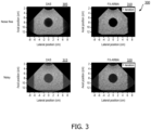
- FIG. 3 shows images 300 of a simulated phantom containing a 40mm-diameter anechoic cyst lesion.
- the images were simulated for a 64-element P4-2 phased array. All images are shown on a 60 dB dynamic range.
- Image 305 was generated using standard delay-and-sum (DAS) beamforming.
- Image 310 was generated using the frequency-space domain (F-X) ARMA filtering technique according to principles of the present disclosure. The F-X ARMA filtering technique was performed once. That is, the process was not repeated with the resulting clean data. Both images 305 and 310 were acquired in the absence of random noise.
- DAS delay-and-sum
- F-X ARMA filtering suppresses off-axis clutter and yields enhanced image contrast.
- Image 315 was generated using standard DAS beamforming and image 320 was generated using F-X ARMA.
- random noise was present in the channel data. Comparing images 315 and 320, F-X ARMA filtering suppresses both random noise and off-axis clutter and yields enhanced image contrast.
- FIG. 4 shows post-processing channel RF data 400 taken from the center scan line (e.g., 0° steering angle) from the images 300 shown in FIG. 3 .
- Image 405 is the channel data for image 305;
- image 410 is the channel data for image 310;
- image 415 is the channel data for image 315; and
- image 420 is the channel data for image 320. Every other channel signal is displayed for clearer visualization.
- Axial samples from sample number 1000 to 2100 correspond to the anechoic cyst lesion shown in images 300.
- image 405 generated using DAS displays small-amplitude off-axis clutter signals.
- image 410 illustrates that the F-X ARMA filtering suppresses much of these off-axis clutter signals while preserving most of the signals in the speckle region (e.g., outside of 1000 ⁇ 2100 sample region).
- the F-X ARMA filtering provides better suppression of both the random noise and the acoustic clutter contributions from the channel RF data.
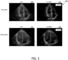
- FIG. 5 shows images 500 of an apical 4-chamber view of a heart. All images are shown on a 60 dB dynamic range. Images 505 and 510 were acquired from an "easy" patient. Images 515 and 520 were acquired from a "difficult" patient. Easy patients have less noisy images than difficult patients. For example, in general, it is often difficult to obtain clear images from overweight patients. That is, an easy patient may be a normal weight patient and a difficult patient may be an overweight patient in some cases. Images 505 and 515 were generated using DAS and images 510 and 510 were generated using the F-X ARMA filtering technique according to principles of the present disclosure. The F-X ARMA filtering technique was performed once. That is, the process was not repeated with the resulting clean data. In both patients, image contrast is significantly reduced in the DAS images 505 and 515 due to the presence of off-axis clutter and reverberation clutter. In comparison, the FX-ARMA images 510 and 520 show a significant amount of image contrast enhancement.
- filtering the ultrasound channel data to acquire clean data using the ARMA filtering technique may provide enhanced image contrast compared to typical image processing techniques such as DAS.
- FIG. 6 shows images 600 of a simulated phantom containing a 40mm-diameter anechoic cyst lesion.
- the images were simulated for a 64-element P4-2 phased array. All images are shown on a 60 dB dynamic range.
- Image 605 was generated using standard delay-and-sum (DAS) beamforming.
- Image 610 was generated using the time-space domain (T-X) ARMA filtering technique according to principles of the invention. The T-X ARMA filtering technique was performed once. That is, the process was not repeated with the resulting clean data. Both images 605 and 610 were acquired in the absence of random noise. Comparing images 605 and 610, T-X ARMA filtering suppresses off-axis clutter and yields enhanced image contrast.
- DAS delay-and-sum
- Image 615 was generated using standard DAS beamforming and image 620 was generated using T-X ARMA.
- random noise was present in the channel data. Comparing images 615 and 620, T-X ARMA filtering suppresses both random noise and off-axis clutter and yields enhanced image contrast.
- the T-X ARMA images 610 and 620 have slightly less contrast than F-X ARMA images 310 and 320 shown in FIG. 3 , the T-X ARMA images still show improved contrast compared to DAS images.
- the T-X ARMA filtering technique may be acceptable and/or preferred in some applications.
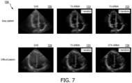
- FIG. 7 shows images 700 of an apical 4-chamber view of a heart. All images are shown on a 60 dB dynamic range. Images 705, 710, and 715 were acquired from an "easy" patient. Images 720, 725, and 730 were acquired from a "difficult" patient. Images 705 and 720 were generated using DAS beamforming. Images 710 and 725 were generated by applying one iteration of the T-X ARMA filtering technique. Images 715 and 730 were generated by applying five iterations of the T-X ARMA filtering technique. That is, the "clean" data from the T-X ARMA filtering technique on the first iteration was fed back into the technique four times.
- filtering the ultrasound channel data to acquire clean data using the ARMA filtering technique may provide enhanced image contrast compared to typical image processing techniques such as DAS, even when using the T-X ARMA method.
- an ARMA filtering technique e.g., ARMA method as described herein may be applied to ultrasound channel data to suppress random noise, acoustic clutter, and/or reverberation clutter which may enhance image contrast. This may improve a clinician's ability to locate, recognize, and/or measure anatomical features in the image. The improved contrast may improve a clinician's ability to make diagnoses based on the ultrasound image.
- a programmable device such as a computer-based system or programmable logic
- the above-described systems and methods can be implemented using any of various known or later developed programming languages, such as "C”, “C++”, “FORTRAN”, “Pascal”, “VHDL” and the like.
- various storage media such as magnetic computer disks, optical disks, electronic memories and the like, can be prepared that can contain information that can direct a device, such as a computer, to implement the above-described systems and/or methods.
- the storage media can provide the information and programs to the device, thus enabling the device to perform functions of the systems and/or methods described herein.
- the computer could receive the information, appropriately configure itself and perform the functions of the various systems and methods outlined in the diagrams and flowcharts above to implement the various functions. That is, the computer could receive various portions of information from the disk relating to different elements of the above-described systems and/or methods, implement the individual systems and/or methods and coordinate the functions of the individual systems and/or methods described above.
- processors described herein can be implemented in hardware, software and firmware. Further, the various methods and parameters are included by way of example only and not in any limiting sense. In view of this disclosure, those of ordinary skill in the art can implement the present teachings in determining their own techniques and needed equipment to affect these techniques, while remaining within the scope of the invention.
- the functionality of one or more of the processors described herein may be incorporated into a fewer number or a single processing unit (e.g., a CPU) and may be implemented using application specific integrated circuits (ASICs) or general purpose processing circuits which are programmed responsive to executable instruction to perform the functions described herein.
- ASICs application specific integrated circuits
- the present system may be extended to other imaging techniques. Additionally, the present system may be used to obtain and/or record image information related to, but not limited to renal, testicular, prostate, breast, ovarian, uterine, thyroid, hepatic, lung, musculoskeletal, splenic, nervous, cardiac, arterial and vascular systems, as well as other imaging applications related to ultrasound-guided interventions and other interventions which may be guided by real-time medical imaging. Further, the present system may also include one or more elements which may be used with non-ultrasound imaging systems with or without real-time imaging components so that they may provide features and advantages of the present system.
- Suitable ultrasonic imaging systems may include a Philips ® ultrasound system which may, for example, support a conventional broadband linear array transducer that may be suitable for small-parts imaging.
Landscapes
- Engineering & Computer Science (AREA)
- Physics & Mathematics (AREA)
- Radar, Positioning & Navigation (AREA)
- Remote Sensing (AREA)
- Computer Networks & Wireless Communication (AREA)
- General Physics & Mathematics (AREA)
- Acoustics & Sound (AREA)
- Health & Medical Sciences (AREA)
- Life Sciences & Earth Sciences (AREA)
- Radiology & Medical Imaging (AREA)
- Molecular Biology (AREA)
- Pathology (AREA)
- Biophysics (AREA)
- Biomedical Technology (AREA)
- Heart & Thoracic Surgery (AREA)
- Medical Informatics (AREA)
- Nuclear Medicine, Radiotherapy & Molecular Imaging (AREA)
- Surgery (AREA)
- Animal Behavior & Ethology (AREA)
- General Health & Medical Sciences (AREA)
- Public Health (AREA)
- Veterinary Medicine (AREA)
- Computer Vision & Pattern Recognition (AREA)
- Ultra Sonic Daignosis Equipment (AREA)
Applications Claiming Priority (2)
| Application Number | Priority Date | Filing Date | Title |
|---|---|---|---|
| US201762562544P | 2017-09-25 | 2017-09-25 | |
| PCT/EP2018/075843 WO2019057981A1 (en) | 2017-09-25 | 2018-09-25 | METHODS AND SYSTEMS FOR PARASITIC ACOUSTIC ECHO FILTERING AND RANDOM NOISE |
Publications (2)
| Publication Number | Publication Date |
|---|---|
| EP3688485A1 EP3688485A1 (en) | 2020-08-05 |
| EP3688485B1 true EP3688485B1 (en) | 2025-02-26 |
Family
ID=63683890
Family Applications (1)
| Application Number | Title | Priority Date | Filing Date |
|---|---|---|---|
| EP18778449.1A Active EP3688485B1 (en) | 2017-09-25 | 2018-09-25 | Methods and systems for filtering of acoustic clutter and random noise |
Country Status (5)
| Country | Link |
|---|---|
| US (1) | US12376833B2 (enExample) |
| EP (1) | EP3688485B1 (enExample) |
| JP (1) | JP7216720B2 (enExample) |
| CN (1) | CN111133331A (enExample) |
| WO (1) | WO2019057981A1 (enExample) |
Families Citing this family (4)
| Publication number | Priority date | Publication date | Assignee | Title |
|---|---|---|---|---|
| CN113488067B (zh) * | 2021-06-30 | 2024-06-25 | 北京小米移动软件有限公司 | 回声消除方法、装置、电子设备和存储介质 |
| US20250099080A1 (en) * | 2023-09-25 | 2025-03-27 | Fujifilm Sonosite, Inc. | Suppressing interference artifacts in ultrasound |
| CN119905098B (zh) * | 2023-10-26 | 2025-12-09 | 中国石油化工股份有限公司 | Das数据中背景噪音的压制方法、系统、介质及设备 |
| CN120000257A (zh) * | 2025-03-06 | 2025-05-16 | 逸超医疗科技(北京)有限公司 | 一种超声成像的多通道接收方法、装置、存储介质及电子设备 |
Family Cites Families (24)
| Publication number | Priority date | Publication date | Assignee | Title |
|---|---|---|---|---|
| US4542744A (en) * | 1983-03-23 | 1985-09-24 | North American Philips Corporation | Method and apparatus for remote tissue identification by statistical modeling and hypothesis testing of echo ultrasound signals |
| US4719923A (en) | 1985-05-06 | 1988-01-19 | American Telephone And Telegraph Company, At&T Bell Laboratories | Non-invasive blood flow measurements utilizing autoregressive analysis with averaged reflection coefficients |
| JP2673311B2 (ja) * | 1989-01-30 | 1997-11-05 | 株式会社トキメック | 信号処理方法及び信号処理装置 |
| US5228009A (en) | 1992-04-10 | 1993-07-13 | Diasonics, Inc. | Parametric clutter elimination |
| US6524249B2 (en) | 1998-11-11 | 2003-02-25 | Spentech, Inc. | Doppler ultrasound method and apparatus for monitoring blood flow and detecting emboli |
| US6547736B1 (en) | 1998-11-11 | 2003-04-15 | Spentech, Inc. | Doppler ultrasound method and apparatus for monitoring blood flow and detecting emboli |
| US6733455B2 (en) * | 1999-08-20 | 2004-05-11 | Zonare Medical Systems, Inc. | System and method for adaptive clutter filtering in ultrasound color flow imaging |
| US6251073B1 (en) * | 1999-08-20 | 2001-06-26 | Novasonics, Inc. | Miniaturized ultrasound apparatus and method |
| US6530885B1 (en) | 2000-03-17 | 2003-03-11 | Atl Ultrasound, Inc. | Spatially compounded three dimensional ultrasonic images |
| US6443896B1 (en) | 2000-08-17 | 2002-09-03 | Koninklijke Philips Electronics N.V. | Method for creating multiplanar ultrasonic images of a three dimensional object |
| JP4542258B2 (ja) | 2000-12-21 | 2010-09-08 | アロカ株式会社 | 超音波診断装置 |
| US6689064B2 (en) | 2001-06-22 | 2004-02-10 | Koninklijke Philips Electronics N.V. | Ultrasound clutter filter |
| AU2002320310A1 (en) | 2001-07-06 | 2003-01-21 | Wisconsin Alumni Research Foundation | Space-time microwave imaging for cancer detection |
| US7803116B2 (en) | 2003-10-03 | 2010-09-28 | University of Washington through its Center for Commericalization | Transcutaneous localization of arterial bleeding by two-dimensional ultrasonic imaging of tissue vibrations |
| US7740583B2 (en) * | 2004-06-30 | 2010-06-22 | General Electric Company | Time delay estimation method and system for use in ultrasound imaging |
| EP2287632A1 (en) * | 2004-07-23 | 2011-02-23 | Bjorn A. J. Angelsen | Ultrasound imaging using non-linear manipulation of forward propagation properties of a pulse |
| JP5529378B2 (ja) * | 2004-08-31 | 2014-06-25 | ユニヴァーシティ オブ ワシントン | 狭窄血管における壁振動を評価するための超音波技法 |
| JP5002397B2 (ja) | 2007-09-28 | 2012-08-15 | 株式会社東芝 | 超音波診断装置及びプログラム |
| US20100113926A1 (en) * | 2008-10-31 | 2010-05-06 | General Electric Company | System and method for clutter filter processing for improved adaptive beamforming |
| US8649999B1 (en) * | 2009-12-28 | 2014-02-11 | Hillcrest Laboratories, Inc. | Methods, devices and systems for determining the zero rate output of a sensor |
| EP2940487B1 (en) * | 2011-10-19 | 2016-07-20 | Verasonics, Inc. | Estimation and display for vector doppler imaging using plane wave transmissions |
| CN103536316B (zh) * | 2013-09-22 | 2015-03-04 | 华中科技大学 | 一种空时平滑相干因子类自适应超声成像方法 |
| WO2017143456A1 (en) * | 2016-02-26 | 2017-08-31 | The University Of Western Ontario | Doppler measurement system and method |
| US10540769B2 (en) * | 2017-03-23 | 2020-01-21 | General Electric Company | Method and system for enhanced ultrasound image visualization by detecting and replacing acoustic shadow artifacts |
-
2018
- 2018-09-25 JP JP2020516731A patent/JP7216720B2/ja active Active
- 2018-09-25 US US16/649,319 patent/US12376833B2/en active Active
- 2018-09-25 CN CN201880061735.1A patent/CN111133331A/zh active Pending
- 2018-09-25 EP EP18778449.1A patent/EP3688485B1/en active Active
- 2018-09-25 WO PCT/EP2018/075843 patent/WO2019057981A1/en not_active Ceased
Also Published As
| Publication number | Publication date |
|---|---|
| WO2019057981A1 (en) | 2019-03-28 |
| US20200261061A1 (en) | 2020-08-20 |
| CN111133331A (zh) | 2020-05-08 |
| EP3688485A1 (en) | 2020-08-05 |
| US12376833B2 (en) | 2025-08-05 |
| JP7216720B2 (ja) | 2023-02-01 |
| JP2020534903A (ja) | 2020-12-03 |
Similar Documents
| Publication | Publication Date | Title |
|---|---|---|
| EP3548920B1 (en) | Methods and systems for filtering ultrasound image clutter | |
| EP3622319B1 (en) | Reverberation artifact cancellation in ultrasonic diagnostic images | |
| US11650300B2 (en) | Ultrasound system and method for suppressing noise using per-channel weighting | |
| EP3641658B1 (en) | Methods for ultrasound system independent attenuation coefficient estimation | |
| US11547389B2 (en) | Methods and systems for ultrasound contrast enhancement | |
| EP3688485B1 (en) | Methods and systems for filtering of acoustic clutter and random noise | |
| US11529125B2 (en) | Methods and systems for processing an ultrasound image | |
| KR101792589B1 (ko) | 빔포머, 진단시스템, 의료영상시스템 및 진단영상을 표시하는 방법 | |
| JP7520103B2 (ja) | エレベーション合成を使用した音響減弱係数の超音波イメージング | |
| EP3639056B1 (en) | Methods and systems for processing an ultrasound image | |
| US11982741B2 (en) | Methods and systems for processing an ultrasound image |
Legal Events
| Date | Code | Title | Description |
|---|---|---|---|
| STAA | Information on the status of an ep patent application or granted ep patent |
Free format text: STATUS: UNKNOWN |
|
| STAA | Information on the status of an ep patent application or granted ep patent |
Free format text: STATUS: THE INTERNATIONAL PUBLICATION HAS BEEN MADE |
|
| PUAI | Public reference made under article 153(3) epc to a published international application that has entered the european phase |
Free format text: ORIGINAL CODE: 0009012 |
|
| STAA | Information on the status of an ep patent application or granted ep patent |
Free format text: STATUS: REQUEST FOR EXAMINATION WAS MADE |
|
| 17P | Request for examination filed |
Effective date: 20200428 |
|
| AK | Designated contracting states |
Kind code of ref document: A1 Designated state(s): AL AT BE BG CH CY CZ DE DK EE ES FI FR GB GR HR HU IE IS IT LI LT LU LV MC MK MT NL NO PL PT RO RS SE SI SK SM TR |
|
| AX | Request for extension of the european patent |
Extension state: BA ME |
|
| DAV | Request for validation of the european patent (deleted) | ||
| DAX | Request for extension of the european patent (deleted) | ||
| STAA | Information on the status of an ep patent application or granted ep patent |
Free format text: STATUS: EXAMINATION IS IN PROGRESS |
|
| 17Q | First examination report despatched |
Effective date: 20220221 |
|
| GRAP | Despatch of communication of intention to grant a patent |
Free format text: ORIGINAL CODE: EPIDOSNIGR1 |
|
| STAA | Information on the status of an ep patent application or granted ep patent |
Free format text: STATUS: GRANT OF PATENT IS INTENDED |
|
| INTG | Intention to grant announced |
Effective date: 20240930 |
|
| GRAS | Grant fee paid |
Free format text: ORIGINAL CODE: EPIDOSNIGR3 |
|
| GRAA | (expected) grant |
Free format text: ORIGINAL CODE: 0009210 |
|
| STAA | Information on the status of an ep patent application or granted ep patent |
Free format text: STATUS: THE PATENT HAS BEEN GRANTED |
|
| AK | Designated contracting states |
Kind code of ref document: B1 Designated state(s): AL AT BE BG CH CY CZ DE DK EE ES FI FR GB GR HR HU IE IS IT LI LT LU LV MC MK MT NL NO PL PT RO RS SE SI SK SM TR |
|
| REG | Reference to a national code |
Ref country code: GB Ref legal event code: FG4D |
|
| REG | Reference to a national code |
Ref country code: CH Ref legal event code: EP |
|
| REG | Reference to a national code |
Ref country code: DE Ref legal event code: R096 Ref document number: 602018079617 Country of ref document: DE |
|
| REG | Reference to a national code |
Ref country code: DE Ref legal event code: R084 Ref document number: 602018079617 Country of ref document: DE |
|
| REG | Reference to a national code |
Ref country code: IE Ref legal event code: FG4D |
|
| REG | Reference to a national code |
Ref country code: GB Ref legal event code: 746 Effective date: 20250331 |
|
| REG | Reference to a national code |
Ref country code: NL Ref legal event code: MP Effective date: 20250226 |
|
| PG25 | Lapsed in a contracting state [announced via postgrant information from national office to epo] |
Ref country code: RS Free format text: LAPSE BECAUSE OF FAILURE TO SUBMIT A TRANSLATION OF THE DESCRIPTION OR TO PAY THE FEE WITHIN THE PRESCRIBED TIME-LIMIT Effective date: 20250526 |
|
| PG25 | Lapsed in a contracting state [announced via postgrant information from national office to epo] |
Ref country code: FI Free format text: LAPSE BECAUSE OF FAILURE TO SUBMIT A TRANSLATION OF THE DESCRIPTION OR TO PAY THE FEE WITHIN THE PRESCRIBED TIME-LIMIT Effective date: 20250226 |
|
| PG25 | Lapsed in a contracting state [announced via postgrant information from national office to epo] |
Ref country code: PL Free format text: LAPSE BECAUSE OF FAILURE TO SUBMIT A TRANSLATION OF THE DESCRIPTION OR TO PAY THE FEE WITHIN THE PRESCRIBED TIME-LIMIT Effective date: 20250226 |
|
| PG25 | Lapsed in a contracting state [announced via postgrant information from national office to epo] |
Ref country code: ES Free format text: LAPSE BECAUSE OF FAILURE TO SUBMIT A TRANSLATION OF THE DESCRIPTION OR TO PAY THE FEE WITHIN THE PRESCRIBED TIME-LIMIT Effective date: 20250226 |
|
| REG | Reference to a national code |
Ref country code: LT Ref legal event code: MG9D |
|
| PG25 | Lapsed in a contracting state [announced via postgrant information from national office to epo] |
Ref country code: IS Free format text: LAPSE BECAUSE OF FAILURE TO SUBMIT A TRANSLATION OF THE DESCRIPTION OR TO PAY THE FEE WITHIN THE PRESCRIBED TIME-LIMIT Effective date: 20250626 Ref country code: NO Free format text: LAPSE BECAUSE OF FAILURE TO SUBMIT A TRANSLATION OF THE DESCRIPTION OR TO PAY THE FEE WITHIN THE PRESCRIBED TIME-LIMIT Effective date: 20250526 |
|
| PG25 | Lapsed in a contracting state [announced via postgrant information from national office to epo] |
Ref country code: NL Free format text: LAPSE BECAUSE OF FAILURE TO SUBMIT A TRANSLATION OF THE DESCRIPTION OR TO PAY THE FEE WITHIN THE PRESCRIBED TIME-LIMIT Effective date: 20250226 |
|
| PG25 | Lapsed in a contracting state [announced via postgrant information from national office to epo] |
Ref country code: HR Free format text: LAPSE BECAUSE OF FAILURE TO SUBMIT A TRANSLATION OF THE DESCRIPTION OR TO PAY THE FEE WITHIN THE PRESCRIBED TIME-LIMIT Effective date: 20250226 |
|
| PG25 | Lapsed in a contracting state [announced via postgrant information from national office to epo] |
Ref country code: LV Free format text: LAPSE BECAUSE OF FAILURE TO SUBMIT A TRANSLATION OF THE DESCRIPTION OR TO PAY THE FEE WITHIN THE PRESCRIBED TIME-LIMIT Effective date: 20250226 Ref country code: PT Free format text: LAPSE BECAUSE OF FAILURE TO SUBMIT A TRANSLATION OF THE DESCRIPTION OR TO PAY THE FEE WITHIN THE PRESCRIBED TIME-LIMIT Effective date: 20250626 |
|
| PG25 | Lapsed in a contracting state [announced via postgrant information from national office to epo] |
Ref country code: GR Free format text: LAPSE BECAUSE OF FAILURE TO SUBMIT A TRANSLATION OF THE DESCRIPTION OR TO PAY THE FEE WITHIN THE PRESCRIBED TIME-LIMIT Effective date: 20250527 Ref country code: BG Free format text: LAPSE BECAUSE OF FAILURE TO SUBMIT A TRANSLATION OF THE DESCRIPTION OR TO PAY THE FEE WITHIN THE PRESCRIBED TIME-LIMIT Effective date: 20250226 |
|
| REG | Reference to a national code |
Ref country code: AT Ref legal event code: MK05 Ref document number: 1771147 Country of ref document: AT Kind code of ref document: T Effective date: 20250226 |
|
| PG25 | Lapsed in a contracting state [announced via postgrant information from national office to epo] |
Ref country code: SE Free format text: LAPSE BECAUSE OF FAILURE TO SUBMIT A TRANSLATION OF THE DESCRIPTION OR TO PAY THE FEE WITHIN THE PRESCRIBED TIME-LIMIT Effective date: 20250226 |
|
| PG25 | Lapsed in a contracting state [announced via postgrant information from national office to epo] |
Ref country code: SM Free format text: LAPSE BECAUSE OF FAILURE TO SUBMIT A TRANSLATION OF THE DESCRIPTION OR TO PAY THE FEE WITHIN THE PRESCRIBED TIME-LIMIT Effective date: 20250226 |
|
| PG25 | Lapsed in a contracting state [announced via postgrant information from national office to epo] |
Ref country code: DK Free format text: LAPSE BECAUSE OF FAILURE TO SUBMIT A TRANSLATION OF THE DESCRIPTION OR TO PAY THE FEE WITHIN THE PRESCRIBED TIME-LIMIT Effective date: 20250226 |
|
| PGFP | Annual fee paid to national office [announced via postgrant information from national office to epo] |
Ref country code: DE Payment date: 20250926 Year of fee payment: 8 |
|
| PG25 | Lapsed in a contracting state [announced via postgrant information from national office to epo] |
Ref country code: IT Free format text: LAPSE BECAUSE OF FAILURE TO SUBMIT A TRANSLATION OF THE DESCRIPTION OR TO PAY THE FEE WITHIN THE PRESCRIBED TIME-LIMIT Effective date: 20250226 |
|
| PGFP | Annual fee paid to national office [announced via postgrant information from national office to epo] |
Ref country code: GB Payment date: 20250923 Year of fee payment: 8 |
|
| PG25 | Lapsed in a contracting state [announced via postgrant information from national office to epo] |
Ref country code: AT Free format text: LAPSE BECAUSE OF FAILURE TO SUBMIT A TRANSLATION OF THE DESCRIPTION OR TO PAY THE FEE WITHIN THE PRESCRIBED TIME-LIMIT Effective date: 20250226 |
|
| PG25 | Lapsed in a contracting state [announced via postgrant information from national office to epo] |
Ref country code: EE Free format text: LAPSE BECAUSE OF FAILURE TO SUBMIT A TRANSLATION OF THE DESCRIPTION OR TO PAY THE FEE WITHIN THE PRESCRIBED TIME-LIMIT Effective date: 20250226 Ref country code: CZ Free format text: LAPSE BECAUSE OF FAILURE TO SUBMIT A TRANSLATION OF THE DESCRIPTION OR TO PAY THE FEE WITHIN THE PRESCRIBED TIME-LIMIT Effective date: 20250226 |
|
| PG25 | Lapsed in a contracting state [announced via postgrant information from national office to epo] |
Ref country code: RO Free format text: LAPSE BECAUSE OF FAILURE TO SUBMIT A TRANSLATION OF THE DESCRIPTION OR TO PAY THE FEE WITHIN THE PRESCRIBED TIME-LIMIT Effective date: 20250226 |
|
| PG25 | Lapsed in a contracting state [announced via postgrant information from national office to epo] |
Ref country code: SK Free format text: LAPSE BECAUSE OF FAILURE TO SUBMIT A TRANSLATION OF THE DESCRIPTION OR TO PAY THE FEE WITHIN THE PRESCRIBED TIME-LIMIT Effective date: 20250226 |