EP3688366B1 - Zylinderhalterung mit flachem profil - Google Patents
Zylinderhalterung mit flachem profil Download PDFInfo
- Publication number
- EP3688366B1 EP3688366B1 EP18779888.9A EP18779888A EP3688366B1 EP 3688366 B1 EP3688366 B1 EP 3688366B1 EP 18779888 A EP18779888 A EP 18779888A EP 3688366 B1 EP3688366 B1 EP 3688366B1
- Authority
- EP
- European Patent Office
- Prior art keywords
- flange
- pressure vessel
- mount
- central plate
- aperture
- Prior art date
- Legal status (The legal status is an assumption and is not a legal conclusion. Google has not performed a legal analysis and makes no representation as to the accuracy of the status listed.)
- Active
Links
Images
Classifications
-
- F—MECHANICAL ENGINEERING; LIGHTING; HEATING; WEAPONS; BLASTING
- F17—STORING OR DISTRIBUTING GASES OR LIQUIDS
- F17C—VESSELS FOR CONTAINING OR STORING COMPRESSED, LIQUEFIED OR SOLIDIFIED GASES; FIXED-CAPACITY GAS-HOLDERS; FILLING VESSELS WITH, OR DISCHARGING FROM VESSELS, COMPRESSED, LIQUEFIED, OR SOLIDIFIED GASES
- F17C13/00—Details of vessels or of the filling or discharging of vessels
- F17C13/08—Mounting arrangements for vessels
-
- B—PERFORMING OPERATIONS; TRANSPORTING
- B60—VEHICLES IN GENERAL
- B60K—ARRANGEMENT OR MOUNTING OF PROPULSION UNITS OR OF TRANSMISSIONS IN VEHICLES; ARRANGEMENT OR MOUNTING OF PLURAL DIVERSE PRIME-MOVERS IN VEHICLES; AUXILIARY DRIVES FOR VEHICLES; INSTRUMENTATION OR DASHBOARDS FOR VEHICLES; ARRANGEMENTS IN CONNECTION WITH COOLING, AIR INTAKE, GAS EXHAUST OR FUEL SUPPLY OF PROPULSION UNITS IN VEHICLES
- B60K15/00—Arrangement in connection with fuel supply of combustion engines or other fuel consuming energy converters, e.g. fuel cells; Mounting or construction of fuel tanks
- B60K15/03—Fuel tanks
- B60K15/03006—Gas tanks
-
- F—MECHANICAL ENGINEERING; LIGHTING; HEATING; WEAPONS; BLASTING
- F17—STORING OR DISTRIBUTING GASES OR LIQUIDS
- F17C—VESSELS FOR CONTAINING OR STORING COMPRESSED, LIQUEFIED OR SOLIDIFIED GASES; FIXED-CAPACITY GAS-HOLDERS; FILLING VESSELS WITH, OR DISCHARGING FROM VESSELS, COMPRESSED, LIQUEFIED, OR SOLIDIFIED GASES
- F17C13/00—Details of vessels or of the filling or discharging of vessels
- F17C13/08—Mounting arrangements for vessels
- F17C13/083—Mounting arrangements for vessels for medium-sized mobile storage vessels, e.g. tank vehicles or railway tank vehicles
-
- F—MECHANICAL ENGINEERING; LIGHTING; HEATING; WEAPONS; BLASTING
- F17—STORING OR DISTRIBUTING GASES OR LIQUIDS
- F17C—VESSELS FOR CONTAINING OR STORING COMPRESSED, LIQUEFIED OR SOLIDIFIED GASES; FIXED-CAPACITY GAS-HOLDERS; FILLING VESSELS WITH, OR DISCHARGING FROM VESSELS, COMPRESSED, LIQUEFIED, OR SOLIDIFIED GASES
- F17C13/00—Details of vessels or of the filling or discharging of vessels
- F17C13/08—Mounting arrangements for vessels
- F17C13/084—Mounting arrangements for vessels for small-sized storage vessels, e.g. compressed gas cylinders or bottles, disposable gas vessels, vessels adapted for automotive use
-
- B—PERFORMING OPERATIONS; TRANSPORTING
- B60—VEHICLES IN GENERAL
- B60K—ARRANGEMENT OR MOUNTING OF PROPULSION UNITS OR OF TRANSMISSIONS IN VEHICLES; ARRANGEMENT OR MOUNTING OF PLURAL DIVERSE PRIME-MOVERS IN VEHICLES; AUXILIARY DRIVES FOR VEHICLES; INSTRUMENTATION OR DASHBOARDS FOR VEHICLES; ARRANGEMENTS IN CONNECTION WITH COOLING, AIR INTAKE, GAS EXHAUST OR FUEL SUPPLY OF PROPULSION UNITS IN VEHICLES
- B60K15/00—Arrangement in connection with fuel supply of combustion engines or other fuel consuming energy converters, e.g. fuel cells; Mounting or construction of fuel tanks
- B60K15/03—Fuel tanks
- B60K2015/03328—Arrangements or special measures related to fuel tanks or fuel handling
-
- F—MECHANICAL ENGINEERING; LIGHTING; HEATING; WEAPONS; BLASTING
- F17—STORING OR DISTRIBUTING GASES OR LIQUIDS
- F17C—VESSELS FOR CONTAINING OR STORING COMPRESSED, LIQUEFIED OR SOLIDIFIED GASES; FIXED-CAPACITY GAS-HOLDERS; FILLING VESSELS WITH, OR DISCHARGING FROM VESSELS, COMPRESSED, LIQUEFIED, OR SOLIDIFIED GASES
- F17C2201/00—Vessel construction, in particular geometry, arrangement or size
- F17C2201/01—Shape
- F17C2201/0104—Shape cylindrical
- F17C2201/0109—Shape cylindrical with exteriorly curved end-piece
-
- F—MECHANICAL ENGINEERING; LIGHTING; HEATING; WEAPONS; BLASTING
- F17—STORING OR DISTRIBUTING GASES OR LIQUIDS
- F17C—VESSELS FOR CONTAINING OR STORING COMPRESSED, LIQUEFIED OR SOLIDIFIED GASES; FIXED-CAPACITY GAS-HOLDERS; FILLING VESSELS WITH, OR DISCHARGING FROM VESSELS, COMPRESSED, LIQUEFIED, OR SOLIDIFIED GASES
- F17C2201/00—Vessel construction, in particular geometry, arrangement or size
- F17C2201/03—Orientation
- F17C2201/035—Orientation with substantially horizontal main axis
-
- F—MECHANICAL ENGINEERING; LIGHTING; HEATING; WEAPONS; BLASTING
- F17—STORING OR DISTRIBUTING GASES OR LIQUIDS
- F17C—VESSELS FOR CONTAINING OR STORING COMPRESSED, LIQUEFIED OR SOLIDIFIED GASES; FIXED-CAPACITY GAS-HOLDERS; FILLING VESSELS WITH, OR DISCHARGING FROM VESSELS, COMPRESSED, LIQUEFIED, OR SOLIDIFIED GASES
- F17C2201/00—Vessel construction, in particular geometry, arrangement or size
- F17C2201/05—Size
- F17C2201/056—Small (<1 m3)
-
- F—MECHANICAL ENGINEERING; LIGHTING; HEATING; WEAPONS; BLASTING
- F17—STORING OR DISTRIBUTING GASES OR LIQUIDS
- F17C—VESSELS FOR CONTAINING OR STORING COMPRESSED, LIQUEFIED OR SOLIDIFIED GASES; FIXED-CAPACITY GAS-HOLDERS; FILLING VESSELS WITH, OR DISCHARGING FROM VESSELS, COMPRESSED, LIQUEFIED, OR SOLIDIFIED GASES
- F17C2205/00—Vessel construction, in particular mounting arrangements, attachments or identifications means
- F17C2205/01—Mounting arrangements
- F17C2205/0153—Details of mounting arrangements
- F17C2205/0192—Details of mounting arrangements with external bearing means
-
- F—MECHANICAL ENGINEERING; LIGHTING; HEATING; WEAPONS; BLASTING
- F17—STORING OR DISTRIBUTING GASES OR LIQUIDS
- F17C—VESSELS FOR CONTAINING OR STORING COMPRESSED, LIQUEFIED OR SOLIDIFIED GASES; FIXED-CAPACITY GAS-HOLDERS; FILLING VESSELS WITH, OR DISCHARGING FROM VESSELS, COMPRESSED, LIQUEFIED, OR SOLIDIFIED GASES
- F17C2205/00—Vessel construction, in particular mounting arrangements, attachments or identifications means
- F17C2205/01—Mounting arrangements
- F17C2205/0153—Details of mounting arrangements
- F17C2205/0196—Details of mounting arrangements with shock absorbing means
-
- F—MECHANICAL ENGINEERING; LIGHTING; HEATING; WEAPONS; BLASTING
- F17—STORING OR DISTRIBUTING GASES OR LIQUIDS
- F17C—VESSELS FOR CONTAINING OR STORING COMPRESSED, LIQUEFIED OR SOLIDIFIED GASES; FIXED-CAPACITY GAS-HOLDERS; FILLING VESSELS WITH, OR DISCHARGING FROM VESSELS, COMPRESSED, LIQUEFIED, OR SOLIDIFIED GASES
- F17C2221/00—Handled fluid, in particular type of fluid
- F17C2221/03—Mixtures
- F17C2221/032—Hydrocarbons
- F17C2221/033—Methane, e.g. natural gas, CNG, LNG, GNL, GNC, PLNG
-
- F—MECHANICAL ENGINEERING; LIGHTING; HEATING; WEAPONS; BLASTING
- F17—STORING OR DISTRIBUTING GASES OR LIQUIDS
- F17C—VESSELS FOR CONTAINING OR STORING COMPRESSED, LIQUEFIED OR SOLIDIFIED GASES; FIXED-CAPACITY GAS-HOLDERS; FILLING VESSELS WITH, OR DISCHARGING FROM VESSELS, COMPRESSED, LIQUEFIED, OR SOLIDIFIED GASES
- F17C2270/00—Applications
- F17C2270/01—Applications for fluid transport or storage
- F17C2270/0165—Applications for fluid transport or storage on the road
- F17C2270/0168—Applications for fluid transport or storage on the road by vehicles
- F17C2270/0178—Cars
-
- Y—GENERAL TAGGING OF NEW TECHNOLOGICAL DEVELOPMENTS; GENERAL TAGGING OF CROSS-SECTIONAL TECHNOLOGIES SPANNING OVER SEVERAL SECTIONS OF THE IPC; TECHNICAL SUBJECTS COVERED BY FORMER USPC CROSS-REFERENCE ART COLLECTIONS [XRACs] AND DIGESTS
- Y02—TECHNOLOGIES OR APPLICATIONS FOR MITIGATION OR ADAPTATION AGAINST CLIMATE CHANGE
- Y02E—REDUCTION OF GREENHOUSE GAS [GHG] EMISSIONS, RELATED TO ENERGY GENERATION, TRANSMISSION OR DISTRIBUTION
- Y02E60/00—Enabling technologies; Technologies with a potential or indirect contribution to GHG emissions mitigation
- Y02E60/30—Hydrogen technology
- Y02E60/32—Hydrogen storage
Definitions
- the present disclosure relates generally to fluid storage and specifically to a mounting bracket for a fluid containment cylinder and a method for mounting the fluid containment cylinder using its boss.
- a particularly suitable fluid containment cylinder is a pressure vessel.
- a typical pressure vessel includes a load bearing outer shell and a fluid impermeable inner liner.
- Suitable pressure vessel shell materials include metals, such as steel; or composites, which may include laminated layers of wound fiberglass filaments or other synthetic filaments bonded together by a thermal-setting or thermoplastic resin.
- the fiber may be fiberglass, aramid, carbon, graphite, or any other generally known fibrous reinforcing material.
- the resin material may be epoxy, polyester, vinyl ester, thermoplastic, or any other suitable resinous material capable of providing fiber-to-fiber bonding, fiber layer-to-layer bonding, and the fragmentation resistance required for the particular application in which the vessel is to be used. Details relevant to the formation of an exemplary pressure vessel are disclosed in U.S. Patent No. 4,838,971 , entitled “Filament Winding Process and Apparatus,” which is incorporated herein by reference.
- An elastomeric or other non-metallic resilient liner or bladder often is disposed within a composite shell to seal the vessel and prevent internal fluids from contacting the composite material.
- the liner can be manufactured by compression molding, blow molding, injection molding, or any other generally known technique.
- the liner can be made of other materials, including steel, aluminum, nickel, titanium, platinum, gold, silver, stainless steel, and any alloys thereof. Such materials can be generally characterized as having a high modulus of elasticity.
- the liner is formed of blow molded high density polyethylene (HDPE).
- the composite construction of the vessels provides numerous advantages such as lightness in weight and resistance to corrosion, fatigue and catastrophic failure. These attributes are due at least in part to the high specific strengths of the reinforcing fibers or filaments.
- Such composite vessels are commonly used for containing a variety of fluids under pressure, such as hydrogen, oxygen, natural gas, nitrogen, methane, propane, and rocket or other fuel, for example.
- pressure vessels can be of any size or configuration.
- the vessels can be heavy or light, single-use (i.e., disposable), reusable, subjected to high pressures (greater than 50 psi, for example), low pressures (less than 50 psi, for example), or used for storing fluids at elevated or cryogenic temperatures, for example. Descriptions relevant to pressure vessels are presented in U.S. Patent No. 5,476,189 , entitled "Pressure vessel with damage mitigating system,” which is hereby incorporated by reference.
- Composite pressure vessels of the character described above originally were developed for aircraft and aerospace applications primarily because of the critical weight restrictions in such vehicles.
- compressed natural gas (CNG) has become more widely used in ground-based vehicles such as buses and cars, however, the composite pressure vessel has become more widely used.
- the structural requirements of a pressure vessel are such that a generally cylindrical shape having rounded ends is a highly-desirable form factor from a standpoint of both strength and packing efficiency.
- the rounded shape can make securing such a pressure vessel to a vehicle difficult.
- the neck of the compressed gas cylinder provides a structural protrusion suitable for attachment by a collar or similar device.
- Certain known designs make use of this feature to secure a gas cylinder.
- Some designs handle misalignment poorly and can place substantial stresses on the neck structure in the event of misalignment.
- Other designs inadequately secure the neck, so that there is a risk that the cylinder may detach from the mount under certain conditions.
- the cylinder can rotate about the principal axis of the cylinder, thereby placing stress on connection lines or other attached hardware.
- many designs have space requirements that accordingly leave less volume available in a limited envelope for the body of the fluid containment cylinder.
- US9388942 discloses systems for modular fuel storage and transportation, including one or more fuel containers, each supported by a fuel container support assembly.
- Each support assembly includes a plurality of detachable end support members such as end support members configured to support the end portions of the fuel container and side support members configured to support the body portion of the fuel container.
- Some of the end support members include neck grooves such that when the end support members are coupled, the neck grooves form an enclosure around the neck portion of the fuel container.
- US8056928 discloses a fuel storage system for a vehicle.
- a frame defines a perimeter structure and has first and second ends, and a generally open central interior portion, and is configured to receive any one of a plurality of vehicle bodies in a body-on-frame vehicle architecture.
- a fuel cell arrangement is disposed adjacent one end of the frame, and a fuel storage tank is disposed in the central interior portion of the frame, along a length of the frame.
- the fuel storage tank provides a source of fuel for the fuel cell, and also acts as a fuel delivery conduit from one end of the frame to the other.
- the fuel storage system can include a non-rigid mounting structure for the fuel tank, thereby substantially isolating the fuel tank from movements of the vehicle frame.
- US2004075034 discloses a support structure for a container that is provided with neck portions on both ends of a longitudinal direction thereof, which includes a first support member for supporting one of the neck portions of the container, a second support member for supporting the other of the neck portions of the container, and elastically pressing the container in the longitudinal direction thereof, and a frame to which the first and second support members are fixed.
- a mount is configured for attachment to a neck of a pressure vessel, as set out in claim 1.
- a pressure vessel having a generally cylindrical shape with dome-shaped ends is quite suitable for high-pressure containment of fluids.
- this shape is not the most efficient in terms of use of volume, as standard mounting methods typically consume space either around the circumference of the pressure vessel (such as when straps around the cylinder body are used) or at the ends of the cylinders (such as with the use of boss mounting methods, wherein mount structures are attached to and extend from the length of the vessel boss).
- mount structures are attached to and extend from the length of the vessel boss.
- the current concept uses a mount structure that is substantially confined to this unused space.
- the disclosed bracket mounts to a vehicle structure using commercially available vibration isolators. These isolators protect the pressure vessel from vehicle vibrations and also absorb axial growth of the cylinder under pressure.
- the mounting bracket can additionally be formed of a spring steel to absorb increased axial motion.
- the bracket is attached to an exterior of the boss with a snap-in retaining ring.
- other attachment mechanisms such as a threaded nuts and flange bolts, for example, can also be used.
- anti-rotation features can be added, including, for example, a keyed boss and bracket assembly, a staked interface after assembly, compressed anti-rotation washers, a bolt flange pattern, or a matched drill stake and bolt hole assembly.
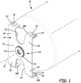
- the drawing figures illustrate an exemplary embodiment of a low-profile cylinder mount configured for assembly with a cylindrical pressure vessel.
- the mount and pressure vessel assembly in an exemplary embodiment, occupies no more than the space or volume of a rectangular prism having a length defined between ends of pressure vessel 10 along longitudinal axis 12. A common width and height of the rectangular prism are defined by a diameter of the cylindrical pressure vessel 10.
- mount 14 in an exemplary embodiment includes bracket 16, vibration isolators 18, and retainer 20, which is configured for attachment to neck 22 of pressure vessel 10 (such as a neck portion of a boss, for example).
- bracket 16 of mount 14 is attached to pressure vessel 10 by passing at least a portion of neck 22 of pressure vessel 10 through aperture 24 of bracket 16. This results in the assembly configuration of bracket 16 and pressure vessel 10 shown in FIG. 1 .
- retainer 20 is positioned on neck 22 to attach bracket 16 to neck 22.
- retainer 20 is provided in the form of a resilient polymeric retaining ring having an annular shape and snap features configured to cooperate with complementary structures on neck 22 and/or aperture 24.
- central aperture 24 of bracket 16 is provided on a substantially planar plate 26 that is oriented substantially orthogonal to longitudinal axis 12.
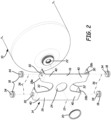
- Flanges 28 extend substantially orthogonally from plate 26 in a direction toward a body of pressure vessel 10.
- An upper flange(s) may be referenced with label 28a, while a lower flange(s) may be referenced with label 28b.
- Flanges 28 are provided, in an exemplary embodiment, with attachment mechanisms 30 configured for the mounting of vibration isolators 18.
- each attachment mechanism 30 is an aperture configured for a snap-fit engagement with a respective vibration isolator 18.
- bracket 16 includes cut out portion 32, which removes material from portions of plate 26 and flange 28.
- bracket 16 Accordingly, savings in materials and weight of bracket 16 can be achieved. It is contemplated that such cut out portions can be shaped and positioned other than as illustrated. However, it is recognized that there will be a trade-off between the strength of bracket 16 and the configuration and amount of material used for forming bracket 16.
- each vibration isolator 18 includes an aperture 34 that is coincident along insertion axis 36 with attachment mechanism 30 on flange 28.
- a fully connected assembly 38 of pressure vessel 10 and mount 14 can be connected via attachment mechanism 30 to another structure, such as a vehicle frame, for example.
- another structure such as a vehicle frame, for example.
- bolts or other fasteners can be inserted through apertures 30, 34 to attach mount 14, and therefore the respective pressure vessel 10, to other structures at flanges 28.
- assembly 38 takes up only the space of a rectangular prism R defined by the length, width and height (e.g., diameter D) of pressure vessel 10. Accordingly, mount 14 offers a low profile means by which to attach pressure vessel 10 to other structures in a limited amount of space.
- each vibration isolator 18 is formed of a resilient, compressible material such as rubber or polymer, for example.
- vibration isolators 18 absorb vibration from a vehicle to which the flanges 28 are attached, thereby dampening such vibrations to isolate pressure vessel 10 therefrom.
- vibration isolators 18 can also absorb some axial growth and/or displacement of pressure vessel 10 along longitudinal axis 12, as well as slight rotational displacement about axis 12.
- Bracket 16 is formed in an exemplary embodiment of a durable and strong metal material such as steel or aluminum, for example.
- bracket 16 can be formed of a spring steel to further deflect and absorb displacement of the pressure vessel 10 relative to the structure to which the mount is attached at attachment mechanism 30 of flanges 28.
- a snap-in retaining ring 20 is disclosed for maintaining bracket 16 on neck 22 of pressure vessel 10, it is contemplated that other structures can be used to achieve this attachment.
- Other suitable retainers include, for example, a threaded nut, a securing flange that passes over at least a portion of neck 22, or a split bracket that can be tightened about neck 22 using a tightening bolt, for example.
- bracket 16 In the illustrated embodiment, no anti-rotation features are explicitly shown to prevent rotation of bracket 16 about longitudinal axis 12 of pressure vessel 10.
- suitable structures include, for example, non-circular keyed configurations of neck 22 and aperture 24 of bracket 16; a staked or locked feature for assembly 38; the use of compressed anti-rotation washers; or the use of keyed bolt.
- a non-limiting example of a disclosed mount 14 is configured for attachment to a neck 22 of a pressure vessel 10, the pressure vessel 10 having a substantially cylindrical body having a diameter D.
- the mount 14 includes bracket 16, vibration isolators 18 and retainer 20.
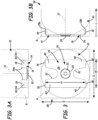
- bracket 16 is configured with a central plate 26 having a height H that is approximately equal to or less than the diameter D, the central plate 26 having a width W that is approximately equal to or less than the diameter D, and the central plate 26 having an aperture 24 therethrough.
- a first flange 28a is located at a first side of the central plate 26, the first flange 28a being oriented substantially perpendicular to the central plate 26 and extending toward the body of pressure vessel 10.
- a second flange 28b is located at a second side of the central plate 26 opposite the first side, the second flange 28b being oriented substantially perpendicular to the central plate 26 and substantially parallel to the first flange 28a, the second flange extending toward the body of pressure vessel 10.
- a first vibration isolator 18 is disposed on the first flange 28a.
- a second vibration isolator 18 disposed on the second flange 28b.
- a retainer 20 is disposed proximate the aperture 24 and is configured to accept at least a portion of the neck 22 of the pressure vessel 10.
- central plate 26 has a cut-out portion 32 that borders at least one of the first and second flanges 28. In an exemplary embodiment, cut-out portion 32 does not border the aperture 24. In an exemplary embodiment, central plate 26 is substantially planar. In an exemplary embodiment, cut-out portion 32 results in the provision of legs 40 on central plate 26. Each leg 40 supports a flange 28. In some embodiments, depending on the material and thickness of central plate 26, each leg 40 can flex independently to accommodate slight movements between pressure vessel 10 and a structure to which mount 14 is attached.
- first flange 28a includes a second aperture 30 therethrough.
- first vibration isolator 18 is connected to the first flange 28a at the second aperture 30.
- the first vibration isolator 18 includes a third aperture 34 that is coincident with the second aperture 30.
- retainer 20 is annular.
- retainer 20 includes a snap feature configured to cooperate with the neck 22.
- a non-limiting example of a disclosed assembly 38 includes a pressure vessel 10 and mount 14.
- the pressure vessel 10 includes a substantially cylindrical body having a diameter D and a length L.
- the pressure vessel 10 also includes neck 22.
- the mount 14 includes a central plate 26 having an aperture 24 therethrough configured to accept a portion of the neck 22 of the pressure vessel 10.
- the mount 14 also includes a first flange 28a located at a first side of the central plate 26 and extending toward the body.
- the mount 14 also includes a second flange 28b located at a second side of the central plate 26 opposite the first side and extending toward the body.
- the assembly 38 occupies no more than a rectangular prism space R defined by the length L, a width equal to the diameter D, and a height equal to the diameter D.
- assembly 38 further includes a first vibration isolator 18 disposed on the first flange 28a and a second vibration isolator 18 disposed on the second flange 28b.
- assembly 38 further includes a retainer 20 disposed proximate the aperture 24 and configured to retain the pressure vessel 10 and mount 14 together in the assembly 38.
Landscapes
- Engineering & Computer Science (AREA)
- Mechanical Engineering (AREA)
- General Engineering & Computer Science (AREA)
- Chemical & Material Sciences (AREA)
- Sustainable Development (AREA)
- Sustainable Energy (AREA)
- Life Sciences & Earth Sciences (AREA)
- Combustion & Propulsion (AREA)
- Transportation (AREA)
- Filling Or Discharging Of Gas Storage Vessels (AREA)
- Cooling, Air Intake And Gas Exhaust, And Fuel Tank Arrangements In Propulsion Units (AREA)
- Pressure Vessels And Lids Thereof (AREA)
- Vibration Prevention Devices (AREA)
- Springs (AREA)
Claims (8)
- Halterung (14), die zur Befestigung an einem Hals (22) eine Druckgefäßes (10) ausgelegt ist, wobei das Druckgefäß (10) einen im Wesentlichen zylindrischen Körper mit einem Durchmesser (D) aufweist, wobei die Halterung (14) Folgendes umfasst:einen Bügel (16), der Folgendes umfasst:eine mittige Platte (26), die eine Höhe (H) aufweist, die etwa gleich oder kleiner als der Durchmesser (D) ist, wobei die mittige Platte (26) eine Breite (W) aufweist, die etwa gleich oder kleiner als der Durchmesser (D) ist, und wobei die mittige Platte (26) eine Öffnung (24) dort hindurch aufweist, wobei die Öffnung (24) dazu ausgelegt ist, einen Durchgang eines Abschnitts des Halses (22) des Druckgefäßes (10) zu ermöglichen;einen ersten Flansch (28a), der sich von einer ersten Seite der mittigen Platte (26) erstreckt, wobei der erste Flansch (28a) im Wesentlichen senkrecht zu der mittigen Platte (26) ausgerichtet und dazu ausgelegt ist, sich hin zu dem Körper zu erstrecken; undeinen zweiten Flansch (28b), der sich von einer der ersten Seite gegenüberliegenden zweiten Seite der mittigen Platte (26) erstreckt, wobei der zweite Flansch (28b) im Wesentlichen senkrecht zu der mittigen Platte (26) und im Wesentlichen parallel zu dem ersten Flansch (28a) ausgerichtet ist, wobei der zweite Flansch (28b) dazu ausgelegt ist, sich hin zu dem Körper zu erstrecken;wobei die mittige Platte (26) einen ausgeschnittenen Abschnitt (32) aufweist, der an mindestens einen des ersten Flanschs (28a) oder des zweiten Flanschs (28b) angrenzt;einen ersten Schwingungsisolator (18), der an dem ersten Flansch (28a) befestigt ist;einen zweiten Schwingungsisolator (18), der an dem zweiten Flansch (28b) befestigt ist; undeinen ringförmigen Halter (20), der dazu ausgelegt ist, einen Abschnitt des Halses (22) des Druckgefäßes (10) auf einer Seite der mittigen Platte (26) gegenüber dem im Wesentlichen zylindrischen Körper des Druckgefäßes (10) zu umgeben und an diesem befestigt zu werden.
- Halterung (14) nach Anspruch 1, wobei der ausgeschnittene Abschnitt (32) nicht an die Öffnung (24) angrenzt.
- Halterung (14) nach einem der Ansprüche 1 oder 2, wobei der erste Flansch (28a) eine zweite Öffnung (30) dort hindurch umfasst.
- Halterung (14) nach Anspruch 3, wobei der erste Schwingungsisolator (18) mit dem ersten Flansch (28a) an der zweiten Öffnung (30) verbunden ist.
- Halterung (14) nach Anspruch 4, wobei der erste Schwingungsisolator (18) eine dritte Öffnung (34) umfasst, die mit der zweiten Öffnung (30) koinzident ist.
- Halterung (14) nach einem der Ansprüche 1-5, wobei der Halter (20) ein Schnappmerkmal umfasst, das dazu ausgelegt ist, mit dem Hals (22) zusammenzuwirken.
- Anordnung (38) des Druckgefäßes (10) und der Halterung (14) nach einem der Ansprüche 1-6, wobei das Druckgefäß (10) eine Länge (L) aufweist; und
wobei die Anordnung (38) nicht mehr als einen rechteckigen Prismenraum einnimmt, der durch die Länge (L), eine Breite gleich dem Durchmesser (D) und eine Höhe gleich dem Durchmesser (D) definiert ist. - Halterung nach einem der Ansprüche 1-6 oder Anordnung nach Anspruch 7, wobei der Bügel (16) Schenkel (40) der mittigen Platte (26) umfasst, die angrenzend an den ausgeschnittenen Abschnitt (32) angeordnet sind, wobei jeder Schenkel einen Flansch trägt.
Priority Applications (1)
| Application Number | Priority Date | Filing Date | Title |
|---|---|---|---|
| EP23152503.1A EP4191121A1 (de) | 2017-09-28 | 2018-09-10 | Flache zylinderlagerung |
Applications Claiming Priority (2)
| Application Number | Priority Date | Filing Date | Title |
|---|---|---|---|
| US201762564507P | 2017-09-28 | 2017-09-28 | |
| PCT/US2018/050148 WO2019067188A1 (en) | 2017-09-28 | 2018-09-10 | LOWER PROFILE CYLINDER MOUNT |
Related Child Applications (2)
| Application Number | Title | Priority Date | Filing Date |
|---|---|---|---|
| EP23152503.1A Division-Into EP4191121A1 (de) | 2017-09-28 | 2018-09-10 | Flache zylinderlagerung |
| EP23152503.1A Division EP4191121A1 (de) | 2017-09-28 | 2018-09-10 | Flache zylinderlagerung |
Publications (3)
| Publication Number | Publication Date |
|---|---|
| EP3688366A1 EP3688366A1 (de) | 2020-08-05 |
| EP3688366C0 EP3688366C0 (de) | 2023-06-07 |
| EP3688366B1 true EP3688366B1 (de) | 2023-06-07 |
Family
ID=63714056
Family Applications (2)
| Application Number | Title | Priority Date | Filing Date |
|---|---|---|---|
| EP23152503.1A Pending EP4191121A1 (de) | 2017-09-28 | 2018-09-10 | Flache zylinderlagerung |
| EP18779888.9A Active EP3688366B1 (de) | 2017-09-28 | 2018-09-10 | Zylinderhalterung mit flachem profil |
Family Applications Before (1)
| Application Number | Title | Priority Date | Filing Date |
|---|---|---|---|
| EP23152503.1A Pending EP4191121A1 (de) | 2017-09-28 | 2018-09-10 | Flache zylinderlagerung |
Country Status (11)
| Country | Link |
|---|---|
| US (3) | US10670191B2 (de) |
| EP (2) | EP4191121A1 (de) |
| JP (3) | JP6968991B2 (de) |
| KR (1) | KR102497428B1 (de) |
| CN (2) | CN113958865B (de) |
| AU (1) | AU2018342145A1 (de) |
| BR (1) | BR112020006000B1 (de) |
| ES (1) | ES2950667T3 (de) |
| PL (1) | PL3688366T3 (de) |
| RU (1) | RU2765794C2 (de) |
| WO (1) | WO2019067188A1 (de) |
Families Citing this family (26)
| Publication number | Priority date | Publication date | Assignee | Title |
|---|---|---|---|---|
| WO2014063018A1 (en) | 2012-10-19 | 2014-04-24 | Agility Fuel Systems, Inc. | Systems and methods for mounting a fuel system |
| US10670191B2 (en) * | 2017-09-28 | 2020-06-02 | Hexagon Technology As | Low profile cylinder mount |
| CA3110459C (en) | 2018-08-24 | 2024-06-18 | Hexagon Purus North America Holdings Inc. | Battery system for heavy duty vehicles |
| US11440399B2 (en) | 2019-03-22 | 2022-09-13 | Agility Fuel Systems Llc | Fuel system mountable to a vehicle frame |
| MX2021012598A (es) | 2019-04-19 | 2023-03-16 | Hexagon Purus North America Holdings Inc | Conjunto de dispositivos de accesorios de parte delantera eléctrica. |
| WO2020215018A1 (en) | 2019-04-19 | 2020-10-22 | Hexagon Purus North America Holdings Inc. | Electric powertrain system for heavy duty vehicles |
| US20200347992A1 (en) | 2019-05-02 | 2020-11-05 | Agility Fuel Systems Llc | Polymeric liner based gas cylinder with reduced permeability |
| FR3099094B1 (fr) * | 2019-07-26 | 2023-04-28 | Faurecia Systemes Dechappement | Système de stockage d’hydrogène |
| EP4041589A4 (de) | 2019-11-26 | 2023-11-08 | Hexagon Purus North America Holdings Inc. | Stromversorgungs- und antriebssteuermodul für ein elektrofahrzeug |
| CN111942620A (zh) * | 2020-08-11 | 2020-11-17 | 中国科学院微小卫星创新研究院 | 电推进贮箱支撑结构及其总装方法 |
| US11959595B2 (en) * | 2020-09-15 | 2024-04-16 | Hyundai Mobis Co., Ltd. | Apparatus for fixing pressure vessel |
| CA3094483A1 (en) * | 2020-09-25 | 2022-03-25 | Richard Bradley Taves | Gas cyclinder mobility aid |
| US11926207B2 (en) | 2020-10-09 | 2024-03-12 | Hexagon Purus North America Holdings Inc. | Battery and auxiliary components for vehicle trailer |
| US12222070B2 (en) * | 2020-10-22 | 2025-02-11 | Iljin Hysolus Co., Ltd. | Hydrogen tank support apparatus |
| EP4259495A4 (de) | 2020-12-11 | 2024-11-06 | Hexagon Purus North America Holdings Inc. | Systeme und verfahren zur abbrechminderung beim anhängen von anhängern |
| EP4313678A1 (de) * | 2021-04-01 | 2024-02-07 | Cryoshelter LH2 GmbH | Montagesystem zur befestigung eines kryobehälters an einem fahrzeugrahmen |
| US12252008B2 (en) * | 2021-06-23 | 2025-03-18 | Agility Fuel Systems Llc | Fuel system with sacrificial neck sleeve |
| US12140271B2 (en) * | 2022-01-05 | 2024-11-12 | Hyundai Motor Company | Pressure vessel assembly and pressure vessel protector |
| CN120051349A (zh) | 2022-11-04 | 2025-05-27 | 村田机械株式会社 | 输送控制系统以及判定方法 |
| CN120380285A (zh) * | 2022-12-22 | 2025-07-25 | 弗萨姆材料美国有限责任公司 | 用于压缩气瓶的防旋转装置 |
| WO2024144594A1 (en) * | 2022-12-29 | 2024-07-04 | Karbonsan Basincli Kaplar Sanayi Ve Ticaret Anonim Sirketi | A profile inserting assembly for pressure tanks |
| JP2024110127A (ja) * | 2023-02-02 | 2024-08-15 | トヨタ自動車株式会社 | タンク搭載構造体 |
| FR3148282B1 (fr) * | 2023-04-28 | 2025-03-21 | Plastic Omnium New Energies France | Dispositif de fixation d’un réservoir destiné à contenir un gaz sous pression amélioré |
| DE102023205083A1 (de) * | 2023-05-31 | 2024-12-05 | Argo Gmbh | Hitzeschild sowie Hochdruckspeicher aufweisend selbiges, Tankspeichersystem und Verfahren zur Ortung |
| DE102024106037A1 (de) | 2024-03-01 | 2025-09-04 | Voith Hystech Gmbh | Drucktank für gasbetriebenes Fahrzeug |
| CN119705047A (zh) * | 2025-02-26 | 2025-03-28 | 长春柏林机械装备有限公司 | 一种安全型车载氢气气瓶安装框架 |
Citations (1)
| Publication number | Priority date | Publication date | Assignee | Title |
|---|---|---|---|---|
| US6378832B1 (en) * | 1999-10-01 | 2002-04-30 | Carrier Corporation | Isolation mounting for a cantilevered load |
Family Cites Families (32)
| Publication number | Priority date | Publication date | Assignee | Title |
|---|---|---|---|---|
| US2729846A (en) * | 1954-01-26 | 1956-01-10 | F Hohlfelder Company | Mounting ring |
| US4838971A (en) | 1987-02-19 | 1989-06-13 | Brunswick Corporation | Filament winding process and apparatus |
| US4920696A (en) * | 1989-02-03 | 1990-05-01 | While Consolidated Industries, Inc. | Refrigeration compressor mount |
| US5295653A (en) * | 1991-10-11 | 1994-03-22 | Toyoda Gosei Co., Ltd. | Vibration insulator having bracket |
| US5476189A (en) | 1993-12-03 | 1995-12-19 | Duvall; Paul F. | Pressure vessel with damage mitigating system |
| US5515997A (en) | 1994-08-17 | 1996-05-14 | Aerojet-General Corporation | Compliant mount for neck of compressed gas cylinder |
| US5524860A (en) * | 1994-09-29 | 1996-06-11 | Ives; Lewis | Universal mounting bracket and method |
| JPH0996256A (ja) | 1995-10-03 | 1997-04-08 | Nippon Soken Inc | Egrガスアシスト噴射システム |
| US6025576A (en) | 1998-03-04 | 2000-02-15 | Beck; Anthony J. | Bulk vessel heater skid for liquefied compressed gases |
| US6249014B1 (en) | 1998-10-01 | 2001-06-19 | Ramtron International Corporation | Hydrogen barrier encapsulation techniques for the control of hydrogen induced degradation of ferroelectric capacitors in conjunction with multilevel metal processing for non-volatile integrated circuit memory devices |
| US6536722B2 (en) | 2001-05-04 | 2003-03-25 | Dynetek Industries Ltd. | Pressure vessel mounting system |
| CA2386443C (en) | 2001-05-17 | 2007-10-23 | Dynetek Industries Ltd. | Replaceable fuel module and method |
| JP3823806B2 (ja) * | 2001-10-30 | 2006-09-20 | 日産自動車株式会社 | 高圧容器の支持構造 |
| US6986490B2 (en) | 2002-06-14 | 2006-01-17 | Hexagon Technology As | Method and apparatus for mounting a fluid containment cylinder |
| DE602005011657D1 (de) | 2004-10-29 | 2009-01-22 | Ford Global Tech Llc | Fahrzeug und brennstoffspeichersystem für ein fahrzeug |
| US7614855B2 (en) * | 2005-03-31 | 2009-11-10 | Arimitsu Of North America, Inc. | Pump and motor assembly |
| DE102006026118A1 (de) | 2006-06-03 | 2007-12-06 | GM Global Technology Operations, Inc., Detroit | Befestigungsanordnung für Gastank eines Kraftfahrzeugs |
| US7976290B2 (en) * | 2007-03-28 | 2011-07-12 | Wei-Chi Wang | Air pump with sheet metal bracket |
| DE102007049837A1 (de) | 2007-10-18 | 2009-05-14 | GM Global Technology Operations, Inc., Detroit | Befestigungsanordnung für Halteband einer Gastank-Haltevorrichtung |
| US8356786B2 (en) | 2008-06-12 | 2013-01-22 | GM Global Technology Operations LLC | Flexible laminated suspension bracket for composite type 4 tanks |
| CA2636100C (en) * | 2008-06-25 | 2015-11-24 | Ncf Industries, Inc. | Intermodal shipping container for transporting compressed gas |
| CN102574463B (zh) | 2009-08-25 | 2015-05-06 | 苏雷亚特·波斯瑞斯克 | 用于机动车辆的cng容器的夹具和紧固件 |
| US8418340B2 (en) | 2011-01-06 | 2013-04-16 | GM Global Technology Operations LLC | Clamping device for tank assembly |
| WO2013083181A1 (en) * | 2011-12-05 | 2013-06-13 | Blue Wave Co S.A. | Iso modal container |
| CN103047534A (zh) * | 2013-01-11 | 2013-04-17 | 扬州诚德钢管有限公司 | 卧式站用储气瓶式容器组 |
| CA2938430A1 (en) | 2013-02-01 | 2014-08-07 | Agility Fuel Systems, Inc. | Modular fuel storage system |
| RU134857U1 (ru) * | 2013-07-04 | 2013-11-27 | Федеральное государственное бюджетное образовательное учреждение высшего профессионального образования "Санкт-Петербургский государственный архитектурно-строительный университет" | Устройство для крепления газовых баллонов к раме транспортного средства и защиты их от коррозии |
| RU142524U1 (ru) * | 2013-12-23 | 2014-06-27 | Открытое акционерное общество "АВТОВАЗ" | Устройство крепления газовых баллонов |
| CN203975535U (zh) * | 2014-07-15 | 2014-12-03 | 石家庄安瑞科气体机械有限公司 | 大容积气瓶的支撑结构、管束式集装箱及气体运输半挂车 |
| JP6688474B2 (ja) * | 2015-11-30 | 2020-04-28 | いすゞ自動車株式会社 | 車両の燃料タンク取付構造 |
| DE102017214077A1 (de) * | 2017-08-11 | 2019-02-14 | Bayerische Motoren Werke Aktiengesellschaft | Kraftfahrzeug |
| US10670191B2 (en) * | 2017-09-28 | 2020-06-02 | Hexagon Technology As | Low profile cylinder mount |
-
2018
- 2018-08-31 US US16/119,181 patent/US10670191B2/en active Active
- 2018-09-10 AU AU2018342145A patent/AU2018342145A1/en not_active Abandoned
- 2018-09-10 RU RU2020114786A patent/RU2765794C2/ru active
- 2018-09-10 KR KR1020207006544A patent/KR102497428B1/ko active Active
- 2018-09-10 BR BR112020006000-3A patent/BR112020006000B1/pt active IP Right Grant
- 2018-09-10 JP JP2020517923A patent/JP6968991B2/ja active Active
- 2018-09-10 PL PL18779888.9T patent/PL3688366T3/pl unknown
- 2018-09-10 EP EP23152503.1A patent/EP4191121A1/de active Pending
- 2018-09-10 EP EP18779888.9A patent/EP3688366B1/de active Active
- 2018-09-10 CN CN202111247049.3A patent/CN113958865B/zh active Active
- 2018-09-10 CN CN201880060676.6A patent/CN111094834B/zh active Active
- 2018-09-10 ES ES18779888T patent/ES2950667T3/es active Active
- 2018-09-10 WO PCT/US2018/050148 patent/WO2019067188A1/en not_active Ceased
-
2020
- 2020-04-21 US US16/854,417 patent/US11041591B2/en active Active
-
2021
- 2021-05-19 US US17/324,315 patent/US11512815B2/en active Active
- 2021-10-27 JP JP2021175755A patent/JP7148697B2/ja active Active
-
2022
- 2022-09-22 JP JP2022151402A patent/JP7422202B2/ja active Active
Patent Citations (1)
| Publication number | Priority date | Publication date | Assignee | Title |
|---|---|---|---|---|
| US6378832B1 (en) * | 1999-10-01 | 2002-04-30 | Carrier Corporation | Isolation mounting for a cantilevered load |
Also Published As
| Publication number | Publication date |
|---|---|
| JP2022009605A (ja) | 2022-01-14 |
| EP3688366C0 (de) | 2023-06-07 |
| BR112020006000A2 (pt) | 2020-09-29 |
| US20190093827A1 (en) | 2019-03-28 |
| US20210270423A1 (en) | 2021-09-02 |
| CN113958865A (zh) | 2022-01-21 |
| CA3073592A1 (en) | 2019-04-04 |
| RU2020114786A (ru) | 2021-10-28 |
| CN111094834A (zh) | 2020-05-01 |
| JP7422202B2 (ja) | 2024-01-25 |
| PL3688366T3 (pl) | 2023-10-02 |
| AU2018342145A1 (en) | 2020-05-14 |
| RU2020114786A3 (de) | 2021-10-28 |
| JP2021500509A (ja) | 2021-01-07 |
| KR102497428B1 (ko) | 2023-02-07 |
| US11512815B2 (en) | 2022-11-29 |
| ES2950667T3 (es) | 2023-10-11 |
| BR112020006000B1 (pt) | 2023-02-28 |
| JP6968991B2 (ja) | 2021-11-24 |
| JP2022177226A (ja) | 2022-11-30 |
| CN111094834B (zh) | 2021-11-19 |
| RU2765794C2 (ru) | 2022-02-03 |
| US10670191B2 (en) | 2020-06-02 |
| JP7148697B2 (ja) | 2022-10-05 |
| US11041591B2 (en) | 2021-06-22 |
| EP3688366A1 (de) | 2020-08-05 |
| CN113958865B (zh) | 2022-11-29 |
| WO2019067188A1 (en) | 2019-04-04 |
| KR20200055709A (ko) | 2020-05-21 |
| US20200248874A1 (en) | 2020-08-06 |
| EP4191121A1 (de) | 2023-06-07 |
Similar Documents
| Publication | Publication Date | Title |
|---|---|---|
| EP3688366B1 (de) | Zylinderhalterung mit flachem profil | |
| US11371659B2 (en) | Boss with internal bearing | |
| US20040056164A1 (en) | Method and apparatus for mounting a fluid containment cylinder | |
| EP1513715B1 (de) | Verfahren und vorrichtung zur montage einer fluidlagerungsflasche | |
| US7984653B2 (en) | Angular mounted high-pressure vessel | |
| JP2005133847A (ja) | 圧力容器 | |
| CA3073592C (en) | Low profile cylinder mount | |
| US20240418327A1 (en) | Sliding vessel mount | |
| WO2024258521A1 (en) | Sliding vessel mount |
Legal Events
| Date | Code | Title | Description |
|---|---|---|---|
| STAA | Information on the status of an ep patent application or granted ep patent |
Free format text: STATUS: UNKNOWN |
|
| STAA | Information on the status of an ep patent application or granted ep patent |
Free format text: STATUS: THE INTERNATIONAL PUBLICATION HAS BEEN MADE |
|
| PUAI | Public reference made under article 153(3) epc to a published international application that has entered the european phase |
Free format text: ORIGINAL CODE: 0009012 |
|
| STAA | Information on the status of an ep patent application or granted ep patent |
Free format text: STATUS: REQUEST FOR EXAMINATION WAS MADE |
|
| 17P | Request for examination filed |
Effective date: 20200221 |
|
| AK | Designated contracting states |
Kind code of ref document: A1 Designated state(s): AL AT BE BG CH CY CZ DE DK EE ES FI FR GB GR HR HU IE IS IT LI LT LU LV MC MK MT NL NO PL PT RO RS SE SI SK SM TR |
|
| AX | Request for extension of the european patent |
Extension state: BA ME |
|
| DAV | Request for validation of the european patent (deleted) | ||
| DAX | Request for extension of the european patent (deleted) | ||
| GRAP | Despatch of communication of intention to grant a patent |
Free format text: ORIGINAL CODE: EPIDOSNIGR1 |
|
| STAA | Information on the status of an ep patent application or granted ep patent |
Free format text: STATUS: GRANT OF PATENT IS INTENDED |
|
| INTG | Intention to grant announced |
Effective date: 20221026 |
|
| GRAS | Grant fee paid |
Free format text: ORIGINAL CODE: EPIDOSNIGR3 |
|
| GRAA | (expected) grant |
Free format text: ORIGINAL CODE: 0009210 |
|
| STAA | Information on the status of an ep patent application or granted ep patent |
Free format text: STATUS: THE PATENT HAS BEEN GRANTED |
|
| AK | Designated contracting states |
Kind code of ref document: B1 Designated state(s): AL AT BE BG CH CY CZ DE DK EE ES FI FR GB GR HR HU IE IS IT LI LT LU LV MC MK MT NL NO PL PT RO RS SE SI SK SM TR |
|
| REG | Reference to a national code |
Ref country code: GB Ref legal event code: FG4D |
|
| REG | Reference to a national code |
Ref country code: CH Ref legal event code: EP Ref country code: AT Ref legal event code: REF Ref document number: 1576075 Country of ref document: AT Kind code of ref document: T Effective date: 20230615 |
|
| REG | Reference to a national code |
Ref country code: DE Ref legal event code: R096 Ref document number: 602018051220 Country of ref document: DE |
|
| U01 | Request for unitary effect filed |
Effective date: 20230628 |
|
| U07 | Unitary effect registered |
Designated state(s): AT BE BG DE DK EE FI FR IT LT LU LV MT NL PT SE SI Effective date: 20230705 |
|
| REG | Reference to a national code |
Ref country code: NO Ref legal event code: T2 Effective date: 20230607 |
|
| REG | Reference to a national code |
Ref country code: LT Ref legal event code: MG9D |
|
| REG | Reference to a national code |
Ref country code: ES Ref legal event code: FG2A Ref document number: 2950667 Country of ref document: ES Kind code of ref document: T3 Effective date: 20231011 |
|
| U20 | Renewal fee for the european patent with unitary effect paid |
Year of fee payment: 6 Effective date: 20230927 |
|
| PG25 | Lapsed in a contracting state [announced via postgrant information from national office to epo] |
Ref country code: RS Free format text: LAPSE BECAUSE OF FAILURE TO SUBMIT A TRANSLATION OF THE DESCRIPTION OR TO PAY THE FEE WITHIN THE PRESCRIBED TIME-LIMIT Effective date: 20230607 Ref country code: HR Free format text: LAPSE BECAUSE OF FAILURE TO SUBMIT A TRANSLATION OF THE DESCRIPTION OR TO PAY THE FEE WITHIN THE PRESCRIBED TIME-LIMIT Effective date: 20230607 Ref country code: GR Free format text: LAPSE BECAUSE OF FAILURE TO SUBMIT A TRANSLATION OF THE DESCRIPTION OR TO PAY THE FEE WITHIN THE PRESCRIBED TIME-LIMIT Effective date: 20230908 |
|
| PG25 | Lapsed in a contracting state [announced via postgrant information from national office to epo] |
Ref country code: SK Free format text: LAPSE BECAUSE OF FAILURE TO SUBMIT A TRANSLATION OF THE DESCRIPTION OR TO PAY THE FEE WITHIN THE PRESCRIBED TIME-LIMIT Effective date: 20230607 |
|
| PG25 | Lapsed in a contracting state [announced via postgrant information from national office to epo] |
Ref country code: IS Free format text: LAPSE BECAUSE OF FAILURE TO SUBMIT A TRANSLATION OF THE DESCRIPTION OR TO PAY THE FEE WITHIN THE PRESCRIBED TIME-LIMIT Effective date: 20231007 |
|
| PG25 | Lapsed in a contracting state [announced via postgrant information from national office to epo] |
Ref country code: SM Free format text: LAPSE BECAUSE OF FAILURE TO SUBMIT A TRANSLATION OF THE DESCRIPTION OR TO PAY THE FEE WITHIN THE PRESCRIBED TIME-LIMIT Effective date: 20230607 Ref country code: SK Free format text: LAPSE BECAUSE OF FAILURE TO SUBMIT A TRANSLATION OF THE DESCRIPTION OR TO PAY THE FEE WITHIN THE PRESCRIBED TIME-LIMIT Effective date: 20230607 Ref country code: RO Free format text: LAPSE BECAUSE OF FAILURE TO SUBMIT A TRANSLATION OF THE DESCRIPTION OR TO PAY THE FEE WITHIN THE PRESCRIBED TIME-LIMIT Effective date: 20230607 Ref country code: IS Free format text: LAPSE BECAUSE OF FAILURE TO SUBMIT A TRANSLATION OF THE DESCRIPTION OR TO PAY THE FEE WITHIN THE PRESCRIBED TIME-LIMIT Effective date: 20231007 Ref country code: CZ Free format text: LAPSE BECAUSE OF FAILURE TO SUBMIT A TRANSLATION OF THE DESCRIPTION OR TO PAY THE FEE WITHIN THE PRESCRIBED TIME-LIMIT Effective date: 20230607 |
|
| REG | Reference to a national code |
Ref country code: DE Ref legal event code: R097 Ref document number: 602018051220 Country of ref document: DE |
|
| PLBE | No opposition filed within time limit |
Free format text: ORIGINAL CODE: 0009261 |
|
| STAA | Information on the status of an ep patent application or granted ep patent |
Free format text: STATUS: NO OPPOSITION FILED WITHIN TIME LIMIT |
|
| REG | Reference to a national code |
Ref country code: CH Ref legal event code: PL |
|
| 26N | No opposition filed |
Effective date: 20240308 |
|
| PG25 | Lapsed in a contracting state [announced via postgrant information from national office to epo] |
Ref country code: MC Free format text: LAPSE BECAUSE OF FAILURE TO SUBMIT A TRANSLATION OF THE DESCRIPTION OR TO PAY THE FEE WITHIN THE PRESCRIBED TIME-LIMIT Effective date: 20230607 |
|
| REG | Reference to a national code |
Ref country code: IE Ref legal event code: MM4A |
|
| PG25 | Lapsed in a contracting state [announced via postgrant information from national office to epo] |
Ref country code: IE Free format text: LAPSE BECAUSE OF NON-PAYMENT OF DUE FEES Effective date: 20230910 |
|
| PG25 | Lapsed in a contracting state [announced via postgrant information from national office to epo] |
Ref country code: CH Free format text: LAPSE BECAUSE OF NON-PAYMENT OF DUE FEES Effective date: 20230930 |
|
| PG25 | Lapsed in a contracting state [announced via postgrant information from national office to epo] |
Ref country code: IE Free format text: LAPSE BECAUSE OF NON-PAYMENT OF DUE FEES Effective date: 20230910 Ref country code: CH Free format text: LAPSE BECAUSE OF NON-PAYMENT OF DUE FEES Effective date: 20230930 |
|
| U20 | Renewal fee for the european patent with unitary effect paid |
Year of fee payment: 7 Effective date: 20240927 |
|
| PGFP | Annual fee paid to national office [announced via postgrant information from national office to epo] |
Ref country code: ES Payment date: 20241001 Year of fee payment: 7 |
|
| PG25 | Lapsed in a contracting state [announced via postgrant information from national office to epo] |
Ref country code: CY Free format text: LAPSE BECAUSE OF FAILURE TO SUBMIT A TRANSLATION OF THE DESCRIPTION OR TO PAY THE FEE WITHIN THE PRESCRIBED TIME-LIMIT; INVALID AB INITIO Effective date: 20180910 |
|
| PG25 | Lapsed in a contracting state [announced via postgrant information from national office to epo] |
Ref country code: HU Free format text: LAPSE BECAUSE OF FAILURE TO SUBMIT A TRANSLATION OF THE DESCRIPTION OR TO PAY THE FEE WITHIN THE PRESCRIBED TIME-LIMIT; INVALID AB INITIO Effective date: 20180910 |
|
| PGFP | Annual fee paid to national office [announced via postgrant information from national office to epo] |
Ref country code: NO Payment date: 20250929 Year of fee payment: 8 |
|
| PGFP | Annual fee paid to national office [announced via postgrant information from national office to epo] |
Ref country code: TR Payment date: 20250822 Year of fee payment: 8 Ref country code: PL Payment date: 20250821 Year of fee payment: 8 |
|
| PGFP | Annual fee paid to national office [announced via postgrant information from national office to epo] |
Ref country code: GB Payment date: 20250929 Year of fee payment: 8 |
|
| U20 | Renewal fee for the european patent with unitary effect paid |
Year of fee payment: 8 Effective date: 20250929 |