EP3687776B1 - Method of manufacturing a moulded article and moulded article obtained thereby - Google Patents
Method of manufacturing a moulded article and moulded article obtained thereby Download PDFInfo
- Publication number
- EP3687776B1 EP3687776B1 EP18779000.1A EP18779000A EP3687776B1 EP 3687776 B1 EP3687776 B1 EP 3687776B1 EP 18779000 A EP18779000 A EP 18779000A EP 3687776 B1 EP3687776 B1 EP 3687776B1
- Authority
- EP
- European Patent Office
- Prior art keywords
- moulding
- mould
- moulded article
- component
- manufacturing
- Prior art date
- Legal status (The legal status is an assumption and is not a legal conclusion. Google has not performed a legal analysis and makes no representation as to the accuracy of the status listed.)
- Active
Links
Images



Classifications
-
- B—PERFORMING OPERATIONS; TRANSPORTING
- B29—WORKING OF PLASTICS; WORKING OF SUBSTANCES IN A PLASTIC STATE IN GENERAL
- B29C—SHAPING OR JOINING OF PLASTICS; SHAPING OF MATERIAL IN A PLASTIC STATE, NOT OTHERWISE PROVIDED FOR; AFTER-TREATMENT OF THE SHAPED PRODUCTS, e.g. REPAIRING
- B29C70/00—Shaping composites, i.e. plastics material comprising reinforcements, fillers or preformed parts, e.g. inserts
- B29C70/04—Shaping composites, i.e. plastics material comprising reinforcements, fillers or preformed parts, e.g. inserts comprising reinforcements only, e.g. self-reinforcing plastics
- B29C70/06—Fibrous reinforcements only
- B29C70/08—Fibrous reinforcements only comprising combinations of different forms of fibrous reinforcements incorporated in matrix material, forming one or more layers, and with or without non-reinforced layers
- B29C70/081—Combinations of fibres of continuous or substantial length and short fibres
-
- B—PERFORMING OPERATIONS; TRANSPORTING
- B29—WORKING OF PLASTICS; WORKING OF SUBSTANCES IN A PLASTIC STATE IN GENERAL
- B29C—SHAPING OR JOINING OF PLASTICS; SHAPING OF MATERIAL IN A PLASTIC STATE, NOT OTHERWISE PROVIDED FOR; AFTER-TREATMENT OF THE SHAPED PRODUCTS, e.g. REPAIRING
- B29C31/00—Handling, e.g. feeding of the material to be shaped, storage of plastics material before moulding; Automation, i.e. automated handling lines in plastics processing plants, e.g. using manipulators or robots
- B29C31/008—Handling preformed parts, e.g. inserts
-
- B—PERFORMING OPERATIONS; TRANSPORTING
- B29—WORKING OF PLASTICS; WORKING OF SUBSTANCES IN A PLASTIC STATE IN GENERAL
- B29C—SHAPING OR JOINING OF PLASTICS; SHAPING OF MATERIAL IN A PLASTIC STATE, NOT OTHERWISE PROVIDED FOR; AFTER-TREATMENT OF THE SHAPED PRODUCTS, e.g. REPAIRING
- B29C43/00—Compression moulding, i.e. applying external pressure to flow the moulding material; Apparatus therefor
- B29C43/02—Compression moulding, i.e. applying external pressure to flow the moulding material; Apparatus therefor of articles of definite length, i.e. discrete articles
- B29C43/18—Compression moulding, i.e. applying external pressure to flow the moulding material; Apparatus therefor of articles of definite length, i.e. discrete articles incorporating preformed parts or layers, e.g. compression moulding around inserts or for coating articles
-
- B—PERFORMING OPERATIONS; TRANSPORTING
- B29—WORKING OF PLASTICS; WORKING OF SUBSTANCES IN A PLASTIC STATE IN GENERAL
- B29C—SHAPING OR JOINING OF PLASTICS; SHAPING OF MATERIAL IN A PLASTIC STATE, NOT OTHERWISE PROVIDED FOR; AFTER-TREATMENT OF THE SHAPED PRODUCTS, e.g. REPAIRING
- B29C43/00—Compression moulding, i.e. applying external pressure to flow the moulding material; Apparatus therefor
- B29C43/02—Compression moulding, i.e. applying external pressure to flow the moulding material; Apparatus therefor of articles of definite length, i.e. discrete articles
- B29C43/20—Making multilayered or multicoloured articles
- B29C43/203—Making multilayered articles
- B29C43/206—Making multilayered articles by pressing the material between two preformed layers, e.g. deformable layers
-
- B—PERFORMING OPERATIONS; TRANSPORTING
- B29—WORKING OF PLASTICS; WORKING OF SUBSTANCES IN A PLASTIC STATE IN GENERAL
- B29C—SHAPING OR JOINING OF PLASTICS; SHAPING OF MATERIAL IN A PLASTIC STATE, NOT OTHERWISE PROVIDED FOR; AFTER-TREATMENT OF THE SHAPED PRODUCTS, e.g. REPAIRING
- B29C43/00—Compression moulding, i.e. applying external pressure to flow the moulding material; Apparatus therefor
- B29C43/32—Component parts, details or accessories; Auxiliary operations
- B29C43/34—Feeding the material to the mould or the compression means
-
- B—PERFORMING OPERATIONS; TRANSPORTING
- B29—WORKING OF PLASTICS; WORKING OF SUBSTANCES IN A PLASTIC STATE IN GENERAL
- B29C—SHAPING OR JOINING OF PLASTICS; SHAPING OF MATERIAL IN A PLASTIC STATE, NOT OTHERWISE PROVIDED FOR; AFTER-TREATMENT OF THE SHAPED PRODUCTS, e.g. REPAIRING
- B29C45/00—Injection moulding, i.e. forcing the required volume of moulding material through a nozzle into a closed mould; Apparatus therefor
- B29C45/14—Injection moulding, i.e. forcing the required volume of moulding material through a nozzle into a closed mould; Apparatus therefor incorporating preformed parts or layers, e.g. injection moulding around inserts or for coating articles
- B29C45/1418—Injection moulding, i.e. forcing the required volume of moulding material through a nozzle into a closed mould; Apparatus therefor incorporating preformed parts or layers, e.g. injection moulding around inserts or for coating articles the inserts being deformed or preformed, e.g. by the injection pressure
- B29C45/14221—Injection moulding, i.e. forcing the required volume of moulding material through a nozzle into a closed mould; Apparatus therefor incorporating preformed parts or layers, e.g. injection moulding around inserts or for coating articles the inserts being deformed or preformed, e.g. by the injection pressure by tools, e.g. cutting means
-
- B—PERFORMING OPERATIONS; TRANSPORTING
- B29—WORKING OF PLASTICS; WORKING OF SUBSTANCES IN A PLASTIC STATE IN GENERAL
- B29C—SHAPING OR JOINING OF PLASTICS; SHAPING OF MATERIAL IN A PLASTIC STATE, NOT OTHERWISE PROVIDED FOR; AFTER-TREATMENT OF THE SHAPED PRODUCTS, e.g. REPAIRING
- B29C45/00—Injection moulding, i.e. forcing the required volume of moulding material through a nozzle into a closed mould; Apparatus therefor
- B29C45/14—Injection moulding, i.e. forcing the required volume of moulding material through a nozzle into a closed mould; Apparatus therefor incorporating preformed parts or layers, e.g. injection moulding around inserts or for coating articles
- B29C45/14778—Injection moulding, i.e. forcing the required volume of moulding material through a nozzle into a closed mould; Apparatus therefor incorporating preformed parts or layers, e.g. injection moulding around inserts or for coating articles the article consisting of a material with particular properties, e.g. porous, brittle
- B29C45/14786—Fibrous material or fibre containing material, e.g. fibre mats or fibre reinforced material
-
- B—PERFORMING OPERATIONS; TRANSPORTING
- B29—WORKING OF PLASTICS; WORKING OF SUBSTANCES IN A PLASTIC STATE IN GENERAL
- B29C—SHAPING OR JOINING OF PLASTICS; SHAPING OF MATERIAL IN A PLASTIC STATE, NOT OTHERWISE PROVIDED FOR; AFTER-TREATMENT OF THE SHAPED PRODUCTS, e.g. REPAIRING
- B29C70/00—Shaping composites, i.e. plastics material comprising reinforcements, fillers or preformed parts, e.g. inserts
- B29C70/04—Shaping composites, i.e. plastics material comprising reinforcements, fillers or preformed parts, e.g. inserts comprising reinforcements only, e.g. self-reinforcing plastics
- B29C70/06—Fibrous reinforcements only
- B29C70/08—Fibrous reinforcements only comprising combinations of different forms of fibrous reinforcements incorporated in matrix material, forming one or more layers, and with or without non-reinforced layers
-
- B—PERFORMING OPERATIONS; TRANSPORTING
- B29—WORKING OF PLASTICS; WORKING OF SUBSTANCES IN A PLASTIC STATE IN GENERAL
- B29C—SHAPING OR JOINING OF PLASTICS; SHAPING OF MATERIAL IN A PLASTIC STATE, NOT OTHERWISE PROVIDED FOR; AFTER-TREATMENT OF THE SHAPED PRODUCTS, e.g. REPAIRING
- B29C70/00—Shaping composites, i.e. plastics material comprising reinforcements, fillers or preformed parts, e.g. inserts
- B29C70/04—Shaping composites, i.e. plastics material comprising reinforcements, fillers or preformed parts, e.g. inserts comprising reinforcements only, e.g. self-reinforcing plastics
- B29C70/28—Shaping operations therefor
- B29C70/30—Shaping by lay-up, i.e. applying fibres, tape or broadsheet on a mould, former or core; Shaping by spray-up, i.e. spraying of fibres on a mould, former or core
- B29C70/34—Shaping by lay-up, i.e. applying fibres, tape or broadsheet on a mould, former or core; Shaping by spray-up, i.e. spraying of fibres on a mould, former or core and shaping or impregnating by compression, i.e. combined with compressing after the lay-up operation
- B29C70/345—Shaping by lay-up, i.e. applying fibres, tape or broadsheet on a mould, former or core; Shaping by spray-up, i.e. spraying of fibres on a mould, former or core and shaping or impregnating by compression, i.e. combined with compressing after the lay-up operation using matched moulds
-
- B—PERFORMING OPERATIONS; TRANSPORTING
- B29—WORKING OF PLASTICS; WORKING OF SUBSTANCES IN A PLASTIC STATE IN GENERAL
- B29C—SHAPING OR JOINING OF PLASTICS; SHAPING OF MATERIAL IN A PLASTIC STATE, NOT OTHERWISE PROVIDED FOR; AFTER-TREATMENT OF THE SHAPED PRODUCTS, e.g. REPAIRING
- B29C37/00—Component parts, details, accessories or auxiliary operations, not covered by group B29C33/00 or B29C35/00
- B29C37/0025—Applying surface layers, e.g. coatings, decorative layers, printed layers, to articles during shaping, e.g. in-mould printing
- B29C37/0028—In-mould coating, e.g. by introducing the coating material into the mould after forming the article
- B29C2037/0042—In-mould coating, e.g. by introducing the coating material into the mould after forming the article the coating being applied in solid sheet form, e.g. as meltable sheet
-
- B—PERFORMING OPERATIONS; TRANSPORTING
- B29—WORKING OF PLASTICS; WORKING OF SUBSTANCES IN A PLASTIC STATE IN GENERAL
- B29C—SHAPING OR JOINING OF PLASTICS; SHAPING OF MATERIAL IN A PLASTIC STATE, NOT OTHERWISE PROVIDED FOR; AFTER-TREATMENT OF THE SHAPED PRODUCTS, e.g. REPAIRING
- B29C37/00—Component parts, details, accessories or auxiliary operations, not covered by group B29C33/00 or B29C35/00
- B29C37/0025—Applying surface layers, e.g. coatings, decorative layers, printed layers, to articles during shaping, e.g. in-mould printing
- B29C37/0028—In-mould coating, e.g. by introducing the coating material into the mould after forming the article
- B29C2037/0046—In-mould printing, in-mould transfer printing
-
- B—PERFORMING OPERATIONS; TRANSPORTING
- B29—WORKING OF PLASTICS; WORKING OF SUBSTANCES IN A PLASTIC STATE IN GENERAL
- B29C—SHAPING OR JOINING OF PLASTICS; SHAPING OF MATERIAL IN A PLASTIC STATE, NOT OTHERWISE PROVIDED FOR; AFTER-TREATMENT OF THE SHAPED PRODUCTS, e.g. REPAIRING
- B29C43/00—Compression moulding, i.e. applying external pressure to flow the moulding material; Apparatus therefor
- B29C43/32—Component parts, details or accessories; Auxiliary operations
- B29C43/34—Feeding the material to the mould or the compression means
- B29C2043/3405—Feeding the material to the mould or the compression means using carrying means
-
- B—PERFORMING OPERATIONS; TRANSPORTING
- B29—WORKING OF PLASTICS; WORKING OF SUBSTANCES IN A PLASTIC STATE IN GENERAL
- B29C—SHAPING OR JOINING OF PLASTICS; SHAPING OF MATERIAL IN A PLASTIC STATE, NOT OTHERWISE PROVIDED FOR; AFTER-TREATMENT OF THE SHAPED PRODUCTS, e.g. REPAIRING
- B29C43/00—Compression moulding, i.e. applying external pressure to flow the moulding material; Apparatus therefor
- B29C43/32—Component parts, details or accessories; Auxiliary operations
- B29C43/34—Feeding the material to the mould or the compression means
- B29C2043/3483—Feeding the material to the mould or the compression means using band or film carriers
-
- B—PERFORMING OPERATIONS; TRANSPORTING
- B29—WORKING OF PLASTICS; WORKING OF SUBSTANCES IN A PLASTIC STATE IN GENERAL
- B29C—SHAPING OR JOINING OF PLASTICS; SHAPING OF MATERIAL IN A PLASTIC STATE, NOT OTHERWISE PROVIDED FOR; AFTER-TREATMENT OF THE SHAPED PRODUCTS, e.g. REPAIRING
- B29C43/00—Compression moulding, i.e. applying external pressure to flow the moulding material; Apparatus therefor
- B29C43/32—Component parts, details or accessories; Auxiliary operations
- B29C43/36—Moulds for making articles of definite length, i.e. discrete articles
- B29C2043/3602—Moulds for making articles of definite length, i.e. discrete articles with means for positioning, fastening or clamping the material to be formed or preforms inside the mould
-
- B—PERFORMING OPERATIONS; TRANSPORTING
- B29—WORKING OF PLASTICS; WORKING OF SUBSTANCES IN A PLASTIC STATE IN GENERAL
- B29C—SHAPING OR JOINING OF PLASTICS; SHAPING OF MATERIAL IN A PLASTIC STATE, NOT OTHERWISE PROVIDED FOR; AFTER-TREATMENT OF THE SHAPED PRODUCTS, e.g. REPAIRING
- B29C45/00—Injection moulding, i.e. forcing the required volume of moulding material through a nozzle into a closed mould; Apparatus therefor
- B29C45/14—Injection moulding, i.e. forcing the required volume of moulding material through a nozzle into a closed mould; Apparatus therefor incorporating preformed parts or layers, e.g. injection moulding around inserts or for coating articles
- B29C45/14008—Inserting articles into the mould
- B29C2045/1404—Inserting articles into the mould feeding inserts cut out from an endless sheet outside the mould
-
- B—PERFORMING OPERATIONS; TRANSPORTING
- B29—WORKING OF PLASTICS; WORKING OF SUBSTANCES IN A PLASTIC STATE IN GENERAL
- B29C—SHAPING OR JOINING OF PLASTICS; SHAPING OF MATERIAL IN A PLASTIC STATE, NOT OTHERWISE PROVIDED FOR; AFTER-TREATMENT OF THE SHAPED PRODUCTS, e.g. REPAIRING
- B29C45/00—Injection moulding, i.e. forcing the required volume of moulding material through a nozzle into a closed mould; Apparatus therefor
- B29C45/14—Injection moulding, i.e. forcing the required volume of moulding material through a nozzle into a closed mould; Apparatus therefor incorporating preformed parts or layers, e.g. injection moulding around inserts or for coating articles
- B29C45/14008—Inserting articles into the mould
- B29C2045/14049—Inserting articles into the mould feeding inserts by a swing arm
-
- B—PERFORMING OPERATIONS; TRANSPORTING
- B29—WORKING OF PLASTICS; WORKING OF SUBSTANCES IN A PLASTIC STATE IN GENERAL
- B29C—SHAPING OR JOINING OF PLASTICS; SHAPING OF MATERIAL IN A PLASTIC STATE, NOT OTHERWISE PROVIDED FOR; AFTER-TREATMENT OF THE SHAPED PRODUCTS, e.g. REPAIRING
- B29C49/00—Blow-moulding, i.e. blowing a preform or parison to a desired shape within a mould; Apparatus therefor
- B29C49/20—Blow-moulding, i.e. blowing a preform or parison to a desired shape within a mould; Apparatus therefor of articles having inserts or reinforcements ; Handling of inserts or reinforcements
- B29C2049/2073—Means for feeding the inserts into the mould, preform or parison, e.g. grippers
- B29C2049/2078—Means for feeding the inserts into the mould, preform or parison, e.g. grippers being retractable during or after blow moulding
-
- B—PERFORMING OPERATIONS; TRANSPORTING
- B29—WORKING OF PLASTICS; WORKING OF SUBSTANCES IN A PLASTIC STATE IN GENERAL
- B29C—SHAPING OR JOINING OF PLASTICS; SHAPING OF MATERIAL IN A PLASTIC STATE, NOT OTHERWISE PROVIDED FOR; AFTER-TREATMENT OF THE SHAPED PRODUCTS, e.g. REPAIRING
- B29C37/00—Component parts, details, accessories or auxiliary operations, not covered by group B29C33/00 or B29C35/00
- B29C37/0025—Applying surface layers, e.g. coatings, decorative layers, printed layers, to articles during shaping, e.g. in-mould printing
- B29C37/0028—In-mould coating, e.g. by introducing the coating material into the mould after forming the article
- B29C37/0032—In-mould coating, e.g. by introducing the coating material into the mould after forming the article the coating being applied upon the mould surface before introducing the moulding compound, e.g. applying a gelcoat
-
- B—PERFORMING OPERATIONS; TRANSPORTING
- B29—WORKING OF PLASTICS; WORKING OF SUBSTANCES IN A PLASTIC STATE IN GENERAL
- B29C—SHAPING OR JOINING OF PLASTICS; SHAPING OF MATERIAL IN A PLASTIC STATE, NOT OTHERWISE PROVIDED FOR; AFTER-TREATMENT OF THE SHAPED PRODUCTS, e.g. REPAIRING
- B29C43/00—Compression moulding, i.e. applying external pressure to flow the moulding material; Apparatus therefor
- B29C43/02—Compression moulding, i.e. applying external pressure to flow the moulding material; Apparatus therefor of articles of definite length, i.e. discrete articles
- B29C43/18—Compression moulding, i.e. applying external pressure to flow the moulding material; Apparatus therefor of articles of definite length, i.e. discrete articles incorporating preformed parts or layers, e.g. compression moulding around inserts or for coating articles
- B29C43/183—Compression moulding, i.e. applying external pressure to flow the moulding material; Apparatus therefor of articles of definite length, i.e. discrete articles incorporating preformed parts or layers, e.g. compression moulding around inserts or for coating articles the preformed layer being a lining, e.g. shaped in the mould before compression moulding, or a preformed shell adapted to the shape of the mould
-
- B—PERFORMING OPERATIONS; TRANSPORTING
- B29—WORKING OF PLASTICS; WORKING OF SUBSTANCES IN A PLASTIC STATE IN GENERAL
- B29C—SHAPING OR JOINING OF PLASTICS; SHAPING OF MATERIAL IN A PLASTIC STATE, NOT OTHERWISE PROVIDED FOR; AFTER-TREATMENT OF THE SHAPED PRODUCTS, e.g. REPAIRING
- B29C43/00—Compression moulding, i.e. applying external pressure to flow the moulding material; Apparatus therefor
- B29C43/32—Component parts, details or accessories; Auxiliary operations
- B29C43/52—Heating or cooling
-
- B—PERFORMING OPERATIONS; TRANSPORTING
- B29—WORKING OF PLASTICS; WORKING OF SUBSTANCES IN A PLASTIC STATE IN GENERAL
- B29C—SHAPING OR JOINING OF PLASTICS; SHAPING OF MATERIAL IN A PLASTIC STATE, NOT OTHERWISE PROVIDED FOR; AFTER-TREATMENT OF THE SHAPED PRODUCTS, e.g. REPAIRING
- B29C45/00—Injection moulding, i.e. forcing the required volume of moulding material through a nozzle into a closed mould; Apparatus therefor
- B29C45/14—Injection moulding, i.e. forcing the required volume of moulding material through a nozzle into a closed mould; Apparatus therefor incorporating preformed parts or layers, e.g. injection moulding around inserts or for coating articles
- B29C45/14065—Positioning or centering articles in the mould
- B29C45/14073—Positioning or centering articles in the mould using means being retractable during injection
-
- B—PERFORMING OPERATIONS; TRANSPORTING
- B29—WORKING OF PLASTICS; WORKING OF SUBSTANCES IN A PLASTIC STATE IN GENERAL
- B29C—SHAPING OR JOINING OF PLASTICS; SHAPING OF MATERIAL IN A PLASTIC STATE, NOT OTHERWISE PROVIDED FOR; AFTER-TREATMENT OF THE SHAPED PRODUCTS, e.g. REPAIRING
- B29C70/00—Shaping composites, i.e. plastics material comprising reinforcements, fillers or preformed parts, e.g. inserts
- B29C70/04—Shaping composites, i.e. plastics material comprising reinforcements, fillers or preformed parts, e.g. inserts comprising reinforcements only, e.g. self-reinforcing plastics
- B29C70/06—Fibrous reinforcements only
- B29C70/10—Fibrous reinforcements only characterised by the structure of fibrous reinforcements, e.g. hollow fibres
- B29C70/16—Fibrous reinforcements only characterised by the structure of fibrous reinforcements, e.g. hollow fibres using fibres of substantial or continuous length
- B29C70/18—Fibrous reinforcements only characterised by the structure of fibrous reinforcements, e.g. hollow fibres using fibres of substantial or continuous length in the form of a mat, e.g. sheet moulding compound [SMC]
-
- B—PERFORMING OPERATIONS; TRANSPORTING
- B29—WORKING OF PLASTICS; WORKING OF SUBSTANCES IN A PLASTIC STATE IN GENERAL
- B29C—SHAPING OR JOINING OF PLASTICS; SHAPING OF MATERIAL IN A PLASTIC STATE, NOT OTHERWISE PROVIDED FOR; AFTER-TREATMENT OF THE SHAPED PRODUCTS, e.g. REPAIRING
- B29C70/00—Shaping composites, i.e. plastics material comprising reinforcements, fillers or preformed parts, e.g. inserts
- B29C70/04—Shaping composites, i.e. plastics material comprising reinforcements, fillers or preformed parts, e.g. inserts comprising reinforcements only, e.g. self-reinforcing plastics
- B29C70/28—Shaping operations therefor
- B29C70/40—Shaping or impregnating by compression not applied
- B29C70/42—Shaping or impregnating by compression not applied for producing articles of definite length, i.e. discrete articles
- B29C70/46—Shaping or impregnating by compression not applied for producing articles of definite length, i.e. discrete articles using matched moulds, e.g. for deforming sheet moulding compounds [SMC] or prepregs
-
- B—PERFORMING OPERATIONS; TRANSPORTING
- B29—WORKING OF PLASTICS; WORKING OF SUBSTANCES IN A PLASTIC STATE IN GENERAL
- B29C—SHAPING OR JOINING OF PLASTICS; SHAPING OF MATERIAL IN A PLASTIC STATE, NOT OTHERWISE PROVIDED FOR; AFTER-TREATMENT OF THE SHAPED PRODUCTS, e.g. REPAIRING
- B29C70/00—Shaping composites, i.e. plastics material comprising reinforcements, fillers or preformed parts, e.g. inserts
- B29C70/04—Shaping composites, i.e. plastics material comprising reinforcements, fillers or preformed parts, e.g. inserts comprising reinforcements only, e.g. self-reinforcing plastics
- B29C70/28—Shaping operations therefor
- B29C70/40—Shaping or impregnating by compression not applied
- B29C70/50—Shaping or impregnating by compression not applied for producing articles of indefinite length, e.g. prepregs, sheet moulding compounds [SMC] or cross moulding compounds [XMC]
- B29C70/502—Shaping or impregnating by compression not applied for producing articles of indefinite length, e.g. prepregs, sheet moulding compounds [SMC] or cross moulding compounds [XMC] by first forming a mat composed of short fibres
-
- B—PERFORMING OPERATIONS; TRANSPORTING
- B29—WORKING OF PLASTICS; WORKING OF SUBSTANCES IN A PLASTIC STATE IN GENERAL
- B29C—SHAPING OR JOINING OF PLASTICS; SHAPING OF MATERIAL IN A PLASTIC STATE, NOT OTHERWISE PROVIDED FOR; AFTER-TREATMENT OF THE SHAPED PRODUCTS, e.g. REPAIRING
- B29C70/00—Shaping composites, i.e. plastics material comprising reinforcements, fillers or preformed parts, e.g. inserts
- B29C70/04—Shaping composites, i.e. plastics material comprising reinforcements, fillers or preformed parts, e.g. inserts comprising reinforcements only, e.g. self-reinforcing plastics
- B29C70/28—Shaping operations therefor
- B29C70/54—Component parts, details or accessories; Auxiliary operations, e.g. feeding or storage of prepregs or SMC after impregnation or during ageing
- B29C70/541—Positioning reinforcements in a mould, e.g. using clamping means for the reinforcement
-
- B—PERFORMING OPERATIONS; TRANSPORTING
- B29—WORKING OF PLASTICS; WORKING OF SUBSTANCES IN A PLASTIC STATE IN GENERAL
- B29C—SHAPING OR JOINING OF PLASTICS; SHAPING OF MATERIAL IN A PLASTIC STATE, NOT OTHERWISE PROVIDED FOR; AFTER-TREATMENT OF THE SHAPED PRODUCTS, e.g. REPAIRING
- B29C70/00—Shaping composites, i.e. plastics material comprising reinforcements, fillers or preformed parts, e.g. inserts
- B29C70/04—Shaping composites, i.e. plastics material comprising reinforcements, fillers or preformed parts, e.g. inserts comprising reinforcements only, e.g. self-reinforcing plastics
- B29C70/28—Shaping operations therefor
- B29C70/54—Component parts, details or accessories; Auxiliary operations, e.g. feeding or storage of prepregs or SMC after impregnation or during ageing
- B29C70/543—Fixing the position or configuration of fibrous reinforcements before or during moulding
-
- B—PERFORMING OPERATIONS; TRANSPORTING
- B29—WORKING OF PLASTICS; WORKING OF SUBSTANCES IN A PLASTIC STATE IN GENERAL
- B29K—INDEXING SCHEME ASSOCIATED WITH SUBCLASSES B29B, B29C OR B29D, RELATING TO MOULDING MATERIALS OR TO MATERIALS FOR MOULDS, REINFORCEMENTS, FILLERS OR PREFORMED PARTS, e.g. INSERTS
- B29K2105/00—Condition, form or state of moulded material or of the material to be shaped
- B29K2105/06—Condition, form or state of moulded material or of the material to be shaped containing reinforcements, fillers or inserts
- B29K2105/08—Condition, form or state of moulded material or of the material to be shaped containing reinforcements, fillers or inserts of continuous length, e.g. cords, rovings, mats, fabrics, strands or yarns
-
- B—PERFORMING OPERATIONS; TRANSPORTING
- B29—WORKING OF PLASTICS; WORKING OF SUBSTANCES IN A PLASTIC STATE IN GENERAL
- B29K—INDEXING SCHEME ASSOCIATED WITH SUBCLASSES B29B, B29C OR B29D, RELATING TO MOULDING MATERIALS OR TO MATERIALS FOR MOULDS, REINFORCEMENTS, FILLERS OR PREFORMED PARTS, e.g. INSERTS
- B29K2105/00—Condition, form or state of moulded material or of the material to be shaped
- B29K2105/06—Condition, form or state of moulded material or of the material to be shaped containing reinforcements, fillers or inserts
- B29K2105/08—Condition, form or state of moulded material or of the material to be shaped containing reinforcements, fillers or inserts of continuous length, e.g. cords, rovings, mats, fabrics, strands or yarns
- B29K2105/0872—Prepregs
-
- B—PERFORMING OPERATIONS; TRANSPORTING
- B29—WORKING OF PLASTICS; WORKING OF SUBSTANCES IN A PLASTIC STATE IN GENERAL
- B29K—INDEXING SCHEME ASSOCIATED WITH SUBCLASSES B29B, B29C OR B29D, RELATING TO MOULDING MATERIALS OR TO MATERIALS FOR MOULDS, REINFORCEMENTS, FILLERS OR PREFORMED PARTS, e.g. INSERTS
- B29K2105/00—Condition, form or state of moulded material or of the material to be shaped
- B29K2105/06—Condition, form or state of moulded material or of the material to be shaped containing reinforcements, fillers or inserts
- B29K2105/08—Condition, form or state of moulded material or of the material to be shaped containing reinforcements, fillers or inserts of continuous length, e.g. cords, rovings, mats, fabrics, strands or yarns
- B29K2105/0872—Prepregs
- B29K2105/0881—Prepregs unidirectional
-
- B—PERFORMING OPERATIONS; TRANSPORTING
- B29—WORKING OF PLASTICS; WORKING OF SUBSTANCES IN A PLASTIC STATE IN GENERAL
- B29K—INDEXING SCHEME ASSOCIATED WITH SUBCLASSES B29B, B29C OR B29D, RELATING TO MOULDING MATERIALS OR TO MATERIALS FOR MOULDS, REINFORCEMENTS, FILLERS OR PREFORMED PARTS, e.g. INSERTS
- B29K2105/00—Condition, form or state of moulded material or of the material to be shaped
- B29K2105/06—Condition, form or state of moulded material or of the material to be shaped containing reinforcements, fillers or inserts
- B29K2105/12—Condition, form or state of moulded material or of the material to be shaped containing reinforcements, fillers or inserts of short lengths, e.g. chopped filaments, staple fibres or bristles
-
- B—PERFORMING OPERATIONS; TRANSPORTING
- B29—WORKING OF PLASTICS; WORKING OF SUBSTANCES IN A PLASTIC STATE IN GENERAL
- B29K—INDEXING SCHEME ASSOCIATED WITH SUBCLASSES B29B, B29C OR B29D, RELATING TO MOULDING MATERIALS OR TO MATERIALS FOR MOULDS, REINFORCEMENTS, FILLERS OR PREFORMED PARTS, e.g. INSERTS
- B29K2105/00—Condition, form or state of moulded material or of the material to be shaped
- B29K2105/06—Condition, form or state of moulded material or of the material to be shaped containing reinforcements, fillers or inserts
- B29K2105/12—Condition, form or state of moulded material or of the material to be shaped containing reinforcements, fillers or inserts of short lengths, e.g. chopped filaments, staple fibres or bristles
- B29K2105/128—Condition, form or state of moulded material or of the material to be shaped containing reinforcements, fillers or inserts of short lengths, e.g. chopped filaments, staple fibres or bristles in the form of a mat
-
- B—PERFORMING OPERATIONS; TRANSPORTING
- B29—WORKING OF PLASTICS; WORKING OF SUBSTANCES IN A PLASTIC STATE IN GENERAL
- B29K—INDEXING SCHEME ASSOCIATED WITH SUBCLASSES B29B, B29C OR B29D, RELATING TO MOULDING MATERIALS OR TO MATERIALS FOR MOULDS, REINFORCEMENTS, FILLERS OR PREFORMED PARTS, e.g. INSERTS
- B29K2105/00—Condition, form or state of moulded material or of the material to be shaped
- B29K2105/24—Condition, form or state of moulded material or of the material to be shaped crosslinked or vulcanised
- B29K2105/243—Partially cured
Definitions
- the present invention relates to a method of manufacturing a moulded article from first and second moulding compounds, wherein each of said moulding compounds comprises a polymer and a fibre reinforcing material embedded within the polymer.
- the invention relates to a method of manufacturing a moulded article by compression moulding, wherein the first moulding compound includes a directional fibre reinforcing material and the second moulding compound includes a non-directional fibre reinforcing material.
- composite materials comprising a polymeric matrix material, such as a thermosetting resin, and a fibre reinforcing material that is embedded within the matrix.
- a polymeric matrix material such as a thermosetting resin
- a fibre reinforcing material that is embedded within the matrix.
- composite materials include for example glass fibre composite materials, wherein a glass fibre mat is embedded within an epoxy resin.
- Products made using these composite materials are characterised generally by having high strength and low weight, as well as being easily moulded. It is also well known to use other materials within the composite, including for example various thermosetting resins for the matrix, and reinforcing fibres made of carbon, glass, metal or natural fibres.
- the moulding compound is supplied in a laminar form, known as sheet moulding compound (SMC), which includes a fibre reinforcing material, for example carbon fibre, embedded within a thermosetting resin.
- SMC sheet moulding compound
- This product may be moulded by placing the SMC sheet in a mould and subjecting it to heat and pressure. This forms the sheet into the desired shape and simultaneously cures the thermosetting resin, thereby fixing the shape of the moulded article.
- This process can be automated making it suitable for the mass production of moulded articles.
- the SMC material generally includes a chopped fibre reinforcing material, wherein the reinforcing fibres are oriented randomly within the moulded article.
- the moulded article therefore has approximately equal strength in all directions. This is ideal for many moulded products, but for certain products, particularly where strength and low weight are critical, it may be preferable to have an increased strength and/or rigidity in one direction. Such directional properties are particularly desirable for example in components used in the automobile and aerospace industries.
- Directional strength can be achieved by the use of directional moulding compounds, in which the reinforcing fibres are continuous and extend preferentially in one or more primary reinforcing directions.
- These directional moulding compounds include pre-impregnated composite materials (so-called "pre-preg” materials) that include a fibrous reinforcing material, for example in the form of a weave or parallel strands, and a thermoset polymeric matrix material that is impregnated into the reinforcing material. The polymeric matrix material may be partially cured to allow easier handling.
- These directional moulding compounds include uni-directional (UD) moulding compounds, in which the reinforcing fibres all run in a single direction substantially parallel to a primary reinforcing axis. In the case of a weave, the material may have two perpendicular primary reinforcing directions, parallel to the warp and weft fibres.
- Directional moulding compounds are available in various laminar forms, including for example sheets and tapes.
- directional continuous fibre reinforcing materials tend to be very much more expensive than non-directional materials such as SMC. This precludes their use in certain applications.
- DE1704194 describes a process for the production of shaped bodies of reinforced plastic material in which the moulded body consisting of core, top and bottom layers is produced in successive steps, the individual layers being sandwiched on top of one another.
- GB 1052773 describes a method of forming a reinforced three-dimensional plastic article, which comprises cutting and bending sheet stock to form a shell, placing the shell in a mould, charging the mould with a plastic chips and applying heat and pressure to polymerize the plastic material of the shell and the chips in said mould.
- the invention provides a method of co-moulding a directional moulding compound and a non-directional moulding compound without disturbing the placement of the reinforcing fibres in the directional moulding compound.
- a moulded article made by the method may thus have a body component made of the non-directional moulding compound and one or more reinforcing elements on the surface of the body component that are made of the directional moulding compound.
- the moulded article can therefore have directional strength/rigidity properties.
- the method utilises the advantages of directional materials, but uses those materials only where they are required, to minimise material costs.
- the method is also capable of being automated or semi-automated, thus allowing the use of mass production techniques.
- moulded articles with a body component made of the non-directional moulding compound and reinforcing elements on opposite sides of the body component that are made of the directional moulding compound.
- the moulded article can therefore have even greater directional strength/rigidity properties.
- the first moulding component is substantially laminar and may be supplied for example in the form of a tape or sheet.
- the first moulding compound includes a uni-directional fibre reinforcing material comprising a plurality of reinforcing fibres that extend substantially parallel to a primary reinforcement direction.
- the first fibre reinforcing material includes continuous reinforcing fibres having a length of at least 20mm.
- the moulded article is formed using a compression moulding process.
- the second moulding component is substantially laminar and may be supplied for example in the form of a sheet.
- the second moulding component may be supplied for example in the form of bulk moulding compound (BMC).
- BMC bulk moulding compound
- the second moulding component comprises a sheet moulding compound.
- the moulded article may be formed using an injection moulding process.
- the second moulding compound may be an injectable moulding compound, consisting for example of granules or pellets.
- the second moulding compound includes reinforcing fibres having a fibre length in the range of 1-100mm.
- the first and second polymers comprise thermoset polymers.
- the first moulding process partially cures the first moulding compound and the second moulding process fully cures the first and second moulding compounds.
- Partially curing the first moulding compound helps it adhere to the mould. It also increases the stiffness and cohesiveness of the first moulding component, which helps it to retain its shape, thus ensuring that the fibres remain correctly aligned during the second stage of the moulding process, in which the second moulding compound is shaped and cured within the mould cavity.
- the first moulding process fully cures the first moulding compound and the second moulding process fully cures the second moulding compound.
- the second moulding process fully cures only the second moulding compound, as the first moulding compound has already been fully cured. Chemical cross-linking between the two polymers cannot then take place, which may result in a slightly less strong bond between the first and second moulding compounds. However, this bond may still be entirely adequate in some applications.
- the first moulding process comprises a first combination of temperature T 1 , pressure P 1 and time t 1 and the second moulding process comprises a second combination of temperature T 2 , pressure P 2 and time t 2 .
- T 1 T 2 . This avoids the need to adjust the temperature of the mould between the first and second moulding processes.
- P 1 P 2 . This avoids the need to adjust the compression pressure of the mould between the first and second moulding processes.
- t 2 m.t 1 where m is in the range 1.5-10, preferably 2-5.
- the first and second polymers may comprise thermoplastic polymers.
- the method includes heating the first and second polymers before placing the first and second polymers in the mould.
- the carrier tool comprises an elastomeric material, for example a silicone rubber.
- the carrier tool is shaped to fit at least a part of the mould cavity, to ensure that it is correctly located within the mould.
- the carrier tool has a thickness that is equal to or greater than the height of the mould cavity at the location of the carrier tool, so that the carrier tool is compressed within the mould cavity when the mould is in a closed configuration.
- the method includes placing auxiliary components of the moulded article in the mould after removing the carrier tool and before placing the second moulding component in the mould.
- auxiliary component such a fixings or fittings, that may be made for example of metal or other materials, to be incorporated into the moulded article.
- a method of manufacturing a moulded article from first and second moulding compounds comprising attaching a first moulding component to a carrier tool, placing the carrier tool and the first moulding component in a mould, applying a first moulding process, removing the carrier tool, placing a second moulding component in the mould, and applying a second moulding process to shape the first and second moulding components and bond the first moulding component to the second moulding component.
- a moulded article comprising a main body and at least one reinforcing element applied to a surface of the main body and co-moulded therewith, wherein:
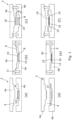
- Figures 1a to 1f illustrate the steps of a manufacturing process for manufacturing a moulded article according to an illustrative embodiment of the invention.
- the moulded article is manufactured using a compression moulding technique and thermosetting polymer.
- the invention is not limited to compression moulding and may also be applicable to other moulding methods including, for example, injection moulding.
- the manufacturing process is also applicable to the use of thermoplastic polymers.
- the mould 2 illustrated in figures 1a to 1f comprises first and second mould parts 4a, 4b which in this embodiment constitute an upper mould platen 4a and a lower mould platen 4b.
- the first and second mould parts are configured for movement between an opened configuration shown in figures 1a, 1c, 1d and 1f and a closed configuration shown in figure 1e .
- the mould 2 is shown in a partially closed configuration in figure 1b .
- a mould void 6 is provided between the first and second mould parts 4a, 4b, as illustrated in figures 1b and 1e .
- An actuator for example a hydraulic ram, is provided for moving the mould parts 4a, 4b between the open and closed configurations.
- the mould parts may for example be made of metal (for example aluminium or stainless steel), and they may include electrical heating elements for heating the mould 2 to the desired moulding temperature.
- the mould 2 may also include one or more ejector pins (not shown) for ejecting a moulded article from the mould void, as is well known in the art.
- first mould part 4a comprises a male mould platen and the second mould part 4b comprises a female mould platen that receives the male mould platen when the mould 2 is in the closed configuration.
- first mould part 4a comprises a male mould platen
- second mould part 4b comprises a female mould platen that receives the male mould platen when the mould 2 is in the closed configuration.
- the relative positions of the male and female mould platens may be reversed or the mould 2 may take some other form as is known in the art.
- the manufacturing process includes a first step, illustrated in figure 1a , in which a carrier tool 8 with one or more attached first moulding components 10 is placed in the mould cavity 6 in a predetermined position, while the mould 2 is in an open configuration.
- the carrier tool 8 is usually shaped to fit at least a part of the mould cavity and may for example consist of an elastomeric sheet, made of silicone rubber or another suitable material that is preferably chemically inert and resistant to temperatures in the range encountered in the moulding process (typically up to about 200C for thermoset polymers).
- the carrier tool 8 may also optionally have surface markings or formations to aid the correct positioning of the first moulding components 10 on the upper and/or lower surfaces of the carrier tool 8.
- An exemplary carrier tool 8 is shown in Fig. 7 and is described below.
- the first moulding components 10, which are attached to the upper and/or lower surfaces of the carrier tool 8, are made from a first moulding compound comprising a first fibre reinforced thermoset polymer.
- the first fibre reinforced polymer comprises a first thermoset polymer as a matrix material and a directional fibre reinforcing material that is embedded in the first thermoset polymer.
- directional fibre reinforcing material means a reinforcing material that includes a plurality of reinforcing fibres that extend preferentially in at least one primary reinforcement direction.
- the directional moulding compound may for example consist of a pre-impregnated composite material (a "pre-preg") that include a fibrous reinforcing material, for example in the form of a weave or parallel strands, and a thermoset polymeric matrix material that is impregnated into the reinforcing material.
- pre-preg pre-impregnated composite material
- fibrous reinforcing material for example in the form of a weave or parallel strands
- thermoset polymeric matrix material that is impregnated into the reinforcing material.
- the material may have two perpendicular primary reinforcing directions, parallel to the warp and weft.
- the directional fibre reinforcing material may be a uni-directional fibre reinforcing material, in which the reinforcing fibres extend substantially parallel to a primary reinforcement
- the first fibre reinforcing material may for example contain carbon fibres, which are preferably continuous fibres.
- the fibres may for example have a length of at least 20mm and may be much longer, for example up to 1000mm or possibly more.
- Other types of reinforcing fibre may also be used, including for example aramid, glass, metal, ultrahigh molecular weight polyethylene, or natural fibres.
- the polymer that forms the matrix of the fibre reinforced polymer may for example be a thermoset resin such as epoxy resin, or any other suitable thermoset polymer, such as polyester or vinyl ester.
- the polymer may alternatively comprise a thermoplastic polymer, for example nylon.
- the matrix material may also include one or more additives or fillers, for example silica, rubber, or carbon nanotubes.
- the first moulding components are preferably provided in a laminar form, consisting for example of sheets or tapes.
- the resin is naturally sticky, allowing the first moulding components 10 to be attached to the surface of the carrier tool 8, simply by applying pressure.
- a low tack adhesive may be used if required, which has sufficient strength to retain the first moulding components in position on the surface of the carrier tool 8, but which also allows the carrier tool 8 to be removed easily from the first moulding components 10 during subsequent steps of the moulding process.
- first moulding components 10 are positioned on the carrier tool 8 such that when the mould 2 is closed the first moulding components 10 contact the inner faces of the first and second mould parts 4a, 4b in the positions where they are required to be located in the final moulded article.
- the carrier tool 8 therefore generally has a thickness that is either approximately equal to the separation of the mould parts 4a, 4b at the location of the carrier tool, or slightly greater than the separation of the mould parts if the carrier tool is made of an elastomeric material that can be compressed.
- FIG. 1b The next step of the manufacturing process is illustrated in figure 1b .
- a first moulding process is applied in which the mould 2 is closed and pressure is applied to the upper mould part 4a as indicated by arrows 11, forcing the first and second mould parts 4a, 4b towards one another. This compresses the carrier tool 8 within the mould cavity 6, and presses the first moulding components 10 against the inner surfaces of the first and second mould parts 4a, 4b.
- the mould 2 has already been pre-heated to the desired moulding temperature, for example 150C. Therefore, when the mould 2 is closed and the first moulding components come into contact with the heated mould, the thermoset polymer starts to cure.
- the mould 2 may be held closed only for long enough for the polymer to partially cure, for example for a time of about one minute, and the mould is then opened as illustrated in figure 1c .
- the first moulding process comprises a combination of temperature T 1 , pressure P 1 and time ti, which together are sufficient to cause partial curing of the first polymer.
- first moulding components 10 Because the first moulding components 10 have been partially cured they stick to the first and second mould parts 4a, 4b, allowing the carrier tool 8 to be removed from the mould, as illustrated in figure 1c . This leaves the first moulding components 10 attached to the first and second mould parts 4a, 4b in the required positions.
- the next step of the manufacturing process is illustrated in figure 1d .
- a second moulding component 12 is placed within the mould cavity 6 between the first and second mould parts 4a, 4b.
- the second moulding component 12 may be made for example from a second moulding compound, which comprises a second polymer and a second fibre reinforcing material embedded within the second polymer.
- the second fibre reinforcing material is a non-directional fibre reinforcing material, which includes a plurality of reinforcing fibres that extend in multiple directions (for example, substantially homogeneously) within the moulding compound.
- the second fibre reinforcing may for example contain carbon fibres, which preferably have a length in the range of 1-100mm.
- the second polymer may be a thermoset resin such as epoxy, or any other suitable thermoset polymer, such as polyester or vinyl ester.
- the second thermoset polymer may be identical to the first thermoset polymer.
- the matrix material may also include one or more additives or fillers, for example silica, rubber or carbon nanotubes.
- the second moulding component is preferably provided in a laminar form, for example as a sheet moulding compound (SMC), which is shaped to fit within the mould cavity 6.
- SMC sheet moulding compound
- HexMC M77 sheet moulding compound from Hexcel.
- auxiliary components for example fittings made of metal or other materials
- the auxiliary components may be positioned within retaining formations in the upper and/or lower mould parts 4a, 4b before the second moulding component 12 is introduced into the mould cavity 6, so that they are integrated into the moulded article.
- the mould 2 is closed and pressure is applied to the first mould part 4a, so that it is pressed towards the second mould part 4b.
- the second moulding component 12 is heated and shaped by the pressing operation, so that it fills and takes the shape of the mould cavity 6.
- first moulding components 10 are attached to the first and second mould parts 4a, 4b, they remain fixed in the required positions and are not disturbed by any movement of the second moulding compound during the pressing process.
- the mould 2 is maintained in the closed configuration for sufficient time to allow the first and second polymers to cure completely, and to allow cross linking between the first and second polymers, so that the directional moulding components 10 are bonded to the surfaces of the non-directional moulding component 12, thereby forming the moulded article 14.
- the mould 2 is opened and the moulded article 14 is removed from the mould. If necessary, the moulded article may be finished for example by removing any flashing that has formed.
- the moulded article 14 includes a main body component 16 that is made of sheet moulding compound, and directional reinforcing elements 18 on one or both sides of the moulded article 14, to provide increased strength and stiffness to the moulded article 14 in selected locations.
- reinforcing elements 18 are provided on both sides of the main body 16 of the moulded article 14. It should be noted that alternatively a reinforcing element or elements may be provided on only one side of the main body 16, according to the strength and stiffness requirements of the moulded article 14.
- a first moulding component 10 may be attached to only one side of the carrier tool 8 before the carrier tool 8 is placed in the mould cavity 6. This may be either the upper side or the lower side of the carrier tool 8. After attaching the first moulding component to the carrier tool 8, the manufacturing process proceeds as described above.
- the first moulding component is only partially cured in the first moulding process.
- the first moulding process may comprise a combination of temperature T 1 , pressure P 1 and time ti, which together are sufficient to fully cure the first polymer.
- the time t 1 and/or the temperature T 1 may be increased to allow full curing. This will ensure that there is no movement of the reinforcing fibres in the first moulding component during subsequent steps of the manufacturing process, for example during the second moulding process, when the second moulding component is formed and cured.
- the bond between the first and second moulding components may be less strong than when the first moulding component is only partially cured in the first moulding process.
- the bond between the first and second moulding components may still be entirely adequate. Therefore, for some applications, this modified process will be suitable and may provide advantages over the manufacturing process in which the first moulding component is only partially cured in the first moulding process.
- thermoset polymers are used in the first and second moulding compounds.
- thermoplastic polymers may be used in the first and second moulding compounds.
- the manufacturing process using thermoplastic polymers is substantially as described above, except that heating of the first and second moulding compounds must be done differently.
- the first moulding compound with the directional fibre reinforcing material will be applied to the carrier tool.
- the carrier tool and the applied first moulding compound are heated to above the meting temperature of the first polymer, and are then placed in a cold mould.
- the mould is then closed and the first moulding compound is allowed to freeze, thus forming the first moulding, which adheres to an inner surface of the mould.
- the mould is then opened and the carrier tool is removed, leaving the formed first moulding component adhered to the mould.
- the second moulding compound for example in the form of sheet moulding compound, is then heated to above the meting temperature of the second polymer, and the heated introduced into the mould second moulding compound is placed in the cold mould. Again the mould is closed, which forms the second moulding compound into the required shape to form the second moulding component and adheres the second moulding component to the first moulding component.
- the second moulding compound is allowed to freeze, thus completing the moulded article. Finally, the mould is opened and the moulded article is removed from the mould.
- the moulded article has a main body component that is made of sheet moulding compound, and directional reinforcing elements on one or both sides of the moulded article 14, that provide increased strength and stiffness to the moulded article 14 in selected locations.
- the invention is also applicable to the manufacture of moulded articles using an injection moulding process.
- the initial steps may be substantially as described above in relation to figures 1a to 1c .
- the mould is closed and an injectable second moulding compound is then injected into the mould to fill the mould cavity.
- the thermoset polymers of the first and second moulding compounds then cure and cross-link, forming the finished moulded article that has a main body made of the second moulding compound and one or more reinforcing elements applied to a surface of the main body.
- the polymers are allowed to cool and set before the moulded article is removed from the mould.
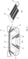
- Figures 2 and 3 illustrate one example of a moulded article 14 made by the method described above.
- the moulded article 14 comprises a tonneau cover for covering the stowed roof of a convertible car.
- Figure 2a illustrates a prior art tonneau cover A made of magnesium alloy, which has numerous ribs B on its lower surface for strength and stiffness (the cover is shown upside down).
- Figures 2b, 2c , 3a and 3b illustrate an equivalent moulded tonneau cover 14 made by the method described above.
- the moulded tonneau cover 14 includes a main body 16 and a plurality of reinforcing elements 18, which are attached to the lower surface of the main body 16 (the tonneau cover 14 is shown upside down).
- the main body 16 is made from sheet moulding compound and includes a non-directional carbon fibre reinforcing material, and the reinforcing elements 18 comprise uni-directional carbon fibre reinforcing fibres in a polymeric matrix.
- the reinforcing elements 18 are bonded to the main body 16 in positions where maximum strength and stiffness are required, and are not provided in locations that do not require such a high level of strength and stiffness. This ensures that the cover 14 has the required performance characteristics, and remains of low weight and relatively low cost.
- the main body 16 is not flat, but instead includes a number of formations 20 in the form of strengthening beads that extend perpendicular to the plane of the cover 14.
- the formations 20 are designed to further increase the strength and stiffness of the cover 14.
- the cover 14 also includes a number of auxiliary components, e.g. metal fasteners 22, which may be used for fastening the cover to the body of a car.
- auxiliary components e.g. metal fasteners 22, which may be used for fastening the cover to the body of a car.
- One of the fasteners 22 is shown in a cut away portion of the cover in figure 2c .
- the fasteners 22 are moulded into the cover 14 during the manufacturing process, as described above in relation to figure 1d .
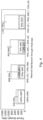
- FIG 4 The results of tests to measure the flexure strength of moulded articles made by the process described above are illustrated in figure 4 .
- Flat samples of the material were tested using a three point bending test.
- the first column illustrates for comparative purposes the test results for a sample comprising 100% sheet moulding compound (SMC), whereas the second, third and fourth columns show the flexure strength for three samples of material made by the described process, comprising a main body of SMC and one or two layers of uni-directional carbon fibre reinforcing material (UD) applied to one or both sides of the SMC main body.
- SMC sheet moulding compound
- the comparative sample made of 100% SMC had a strength of 536MPa
- a sample comprising 70% SMC and 30% UD in a double ply layer on the upper surface of the SMC had a strength of 868MPa
- a sample comprising 70% SMC and 30% UD in a two ply layer on the lower surface of the SMC had a strength of 945MPa
- a sample comprising 70% SMC and 2 single ply layers of UD on the upper and lower faces of the SMC had a strength of 1307MPa. It appears from these tests that the symmetrical arrangement shown in column 4 is by far the best solution, both in performance and consistency.
- Figure 5 illustrates the steps of a process for manufacturing moulded articles according to an embodiment of the invention, which may optionally be fully or partially automated.
- the first moulding component comprising a directional fibre reinforcement (indicated as "UD") is deposited on the carrier tool (indicated as "cork”).
- the carrier tool is then loaded at step 32 into the mould, which is closed at step 34.
- a first moulding process comprising a first combination of time, temperature and pressure (t 1 , T 1 , P 1 ) is applied at step 36. This partially cures the first moulding component (indicated as "UD B-staging”); step 38.
- the mould is opened at step 40 and the carrier tool ("cork") is unloaded from the mould: step 42.
- the carrier tool is cleaned and allowed to cool, ready for re-use: steps 44,46.
- auxiliary components such as metal inserts (if required) may be placed in the mould in the appropriate locations: step 48.
- the second moulding component that comprises a non-directional fibre reinforcing material, for example SMC is prepared by cutting the second moulded component to the desired shape to match the shape of the mould: step 50. The second moulding component is then weighed for accuracy and stacked ready for use: steps 52, 54.
- step 56 the second moulding component is loaded into the mould, and the mould is then closed: step 58.
- a second moulding process comprising a second combination of time, temperature and pressure (t 2 , T 2 , P 2 ) is applied at step 60. This cures the second moulding component and completes curing of the first moulding component, and causes cross-linking between the first and second moulding components to form the finished moulded article: step 62.
- the mould is opened at step 64 and the moulded article is released at step 66.
- the moulded article may then undergo finishing operations including for example trimming away excess flash, at step 68.
- the mould is then prepared for another moulding operation by applying a release agent at step 70 and allowing the release agent to cure at step 72. This process may then be repeated as necessary.
- Figure 6 is an isometric view of a moulded article 80 with a unidirectional fibre reinforcing element 82
- Figure 7 is an isometric view of a carrier tool 84 carrying the unidirectional fibre reinforcing element 82.
- the unidirectional fibre reinforcing element 82 is made of a first moulding compound that comprises a first polymer and a first fibre reinforcing material embedded within the first polymer.
- the first fibre reinforcing material is a directional fibre reinforcing material that includes, in this case, a plurality of continuous reinforcing fibres that extend preferentially in at least one primary reinforcement direction D within the first moulding compound.
- the moulded article 80 comprises a main body 84 that is made of a second moulding compound comprising a second polymer and a second fibre reinforcing material embedded within the second polymer.
- the second fibre reinforcing material is a non-directional fibre reinforcing material that includes a plurality of reinforcing fibres that extend in multiple directions within the second moulding compound.
- the moulded article 80 is a load-bearing frame structure that includes an upper element 86, a lower element 88 and two transverse elements 90, 92 that interconnect the upper element 86 and the lower element 88.
- the upper element 86 has the greatest load bearing requirement and is subjected in use to tensile forces acting in the direction of the longitudinal axis of the upper element.
- the reinforcing fibres of the unidirectional fibre reinforcing element 82 are orientated such that the primary reinforcement direction D extends parallel to the longitudinal axis of the upper element 86, in order to increase the strength and stiffness of the upper element 86 in the load bearing direction.
- the carrier tool 84 mimics the shape of the upper element 86 of the moulded article 80.
- the unidirectional fibre reinforcing element 82 is attached to the surface of the carrier tool 84 in the position where it is to be placed on the surface of the moulded article. This ensures that when the carrier tool 84 and the attached unidirectional fibre reinforcing element 82 are placed in the mould for the first moulding process, the unidirectional fibre reinforcing element 82 is located in precisely the right position within the mould, so that it is correctly located on the surface of the moulded article 80.
- the carrier tool 84 is made, for example, from silicone rubber.
Landscapes
- Engineering & Computer Science (AREA)
- Mechanical Engineering (AREA)
- Chemical & Material Sciences (AREA)
- Composite Materials (AREA)
- Manufacturing & Machinery (AREA)
- Robotics (AREA)
- Textile Engineering (AREA)
- Casting Or Compression Moulding Of Plastics Or The Like (AREA)
Description
- The present invention relates to a method of manufacturing a moulded article from first and second moulding compounds, wherein each of said moulding compounds comprises a polymer and a fibre reinforcing material embedded within the polymer.
- In particular, but not exclusively, the invention relates to a method of manufacturing a moulded article by compression moulding, wherein the first moulding compound includes a directional fibre reinforcing material and the second moulding compound includes a non-directional fibre reinforcing material.
- It has been known for many years to manufacture moulded articles using composite materials comprising a polymeric matrix material, such as a thermosetting resin, and a fibre reinforcing material that is embedded within the matrix. Such composite materials include for example glass fibre composite materials, wherein a glass fibre mat is embedded within an epoxy resin.
- Products made using these composite materials are characterised generally by having high strength and low weight, as well as being easily moulded. It is also well known to use other materials within the composite, including for example various thermosetting resins for the matrix, and reinforcing fibres made of carbon, glass, metal or natural fibres.
- In a known compression moulding process, the moulding compound is supplied in a laminar form, known as sheet moulding compound (SMC), which includes a fibre reinforcing material, for example carbon fibre, embedded within a thermosetting resin. This product may be moulded by placing the SMC sheet in a mould and subjecting it to heat and pressure. This forms the sheet into the desired shape and simultaneously cures the thermosetting resin, thereby fixing the shape of the moulded article. This process can be automated making it suitable for the mass production of moulded articles.
- The SMC material generally includes a chopped fibre reinforcing material, wherein the reinforcing fibres are oriented randomly within the moulded article. The moulded article therefore has approximately equal strength in all directions. This is ideal for many moulded products, but for certain products, particularly where strength and low weight are critical, it may be preferable to have an increased strength and/or rigidity in one direction. Such directional properties are particularly desirable for example in components used in the automobile and aerospace industries.
- Directional strength can be achieved by the use of directional moulding compounds, in which the reinforcing fibres are continuous and extend preferentially in one or more primary reinforcing directions. These directional moulding compounds include pre-impregnated composite materials (so-called "pre-preg" materials) that include a fibrous reinforcing material, for example in the form of a weave or parallel strands, and a thermoset polymeric matrix material that is impregnated into the reinforcing material. The polymeric matrix material may be partially cured to allow easier handling. These directional moulding compounds include uni-directional (UD) moulding compounds, in which the reinforcing fibres all run in a single direction substantially parallel to a primary reinforcing axis. In the case of a weave, the material may have two perpendicular primary reinforcing directions, parallel to the warp and weft fibres. Directional moulding compounds are available in various laminar forms, including for example sheets and tapes.
- However, directional continuous fibre reinforcing materials tend to be very much more expensive than non-directional materials such as SMC. This precludes their use in certain applications.
- It has been proposed to use a combination of uni-directional and non-directional moulding compounds in order to provide a high-directional strength while avoiding some of the additional cost resulting from the use of uni-directional materials. However, in practice it has been found that when directional and non-directional moulding compounds are moulded together for example by compression moulding, material flow within the mould disrupts the placement of the directional fibres. The fibres are then unable to provide the directional strength that is required. This results in the technical problem that these materials are unable to provide the required combination of strength, low weight and reasonable cost.
-
DE1704194 describes a process for the production of shaped bodies of reinforced plastic material in which the moulded body consisting of core, top and bottom layers is produced in successive steps, the individual layers being sandwiched on top of one another. -
GB 1052773 - It is an objective of the present invention to provide a method of manufacturing a moulded article, which mitigates one or more of the aforesaid problems.
- According to one aspect of the present invention there is provided a method of manufacturing a moulded article from first and second moulding compounds, wherein:
- the first moulding compound comprises a first polymer and a first fibre reinforcing material embedded within the first polymer, wherein the first fibre reinforcing material is a directional fibre reinforcing material that includes a plurality of reinforcing fibres that extend preferentially in at least one primary reinforcement direction within the first moulding compound, and
- the second moulding compound comprises a second polymer and a second fibre reinforcing material embedded within the second polymer, wherein the second fibre reinforcing material is a non-directional fibre reinforcing material that includes a plurality of reinforcing fibres that extend in multiple directions within the second moulding compound, the method comprising:
- attaching a first moulding component to a carrier tool, said first moulding component comprising said first moulding compound,
- placing the carrier tool and the attached first moulding component in a mould comprising first and second mould parts that are configurable in opened and closed configurations, wherein a mould cavity is defined between the first and second mould parts in the closed configuration,
- closing the mould and applying a first moulding process so that the first moulding component adheres to the first mould part,
- opening the mould and removing the carrier tool while leaving the first moulding component adhered to the first mould part,
- either (i) placing a second moulding component in the mould, said second moulding component comprising said second moulding compound, then closing the mould, or (ii) closing the mould, then injecting a second moulding component into the mould, said second moulding component comprising said second moulding compound,
- applying a second moulding process to shape the first and second moulding components to the mould cavity, and bond the first moulding component to the second moulding component to form a moulded article, and
- opening the mould and removing the moulded article.
- The invention provides a method of co-moulding a directional moulding compound and a non-directional moulding compound without disturbing the placement of the reinforcing fibres in the directional moulding compound. A moulded article made by the method may thus have a body component made of the non-directional moulding compound and one or more reinforcing elements on the surface of the body component that are made of the directional moulding compound. The moulded article can therefore have directional strength/rigidity properties. The method utilises the advantages of directional materials, but uses those materials only where they are required, to minimise material costs. The method is also capable of being automated or semi-automated, thus allowing the use of mass production techniques.
- In an embodiment the method comprises:
- attaching first moulding components to opposite sides the carrier tool, each of said first moulding components comprising said first moulding compound,
- placing the carrier tool and the attached first moulding components in the mould, closing the mould and applying the first moulding process so that at least one first moulding component adheres to the first mould part and at least one first moulding component adheres to the second mould part,
- opening the mould and removing the carrier tool while leaving the first moulding components adhered to the first and second mould parts, and
- either (i) placing the second moulding component in the mould, then closing the mould, or (ii) closing the mould, then injecting a second moulding component into the mould, said second moulding component comprising said second moulding compound,
- applying the second moulding process to shape the first and second moulding components to the mould cavity and bond the first moulding components to opposite sides of the second moulding component to form a moulded article, and
- opening the mould and removing the moulded article.
- This option allows the production of moulded articles with a body component made of the non-directional moulding compound and reinforcing elements on opposite sides of the body component that are made of the directional moulding compound. The moulded article can therefore have even greater directional strength/rigidity properties.
- Optionally, the first moulding component is substantially laminar and may be supplied for example in the form of a tape or sheet.
- Optionally, the first moulding compound includes a uni-directional fibre reinforcing material comprising a plurality of reinforcing fibres that extend substantially parallel to a primary reinforcement direction.
- Optionally, the first fibre reinforcing material includes continuous reinforcing fibres having a length of at least 20mm.
- Optionally, the moulded article is formed using a compression moulding process.
- Optionally, the second moulding component is substantially laminar and may be supplied for example in the form of a sheet. Alternatively, the second moulding component may be supplied for example in the form of bulk moulding compound (BMC).
- Optionally, the second moulding component comprises a sheet moulding compound.
- Alternatively, the moulded article may be formed using an injection moulding process. In this case the second moulding compound may be an injectable moulding compound, consisting for example of granules or pellets.
- Optionally, the second moulding compound includes reinforcing fibres having a fibre length in the range of 1-100mm.
- Optionally, the first and second polymers comprise thermoset polymers.
- Optionally, the first moulding process partially cures the first moulding compound and the second moulding process fully cures the first and second moulding compounds. This ensures chemical cross-linking between the two polymers, thus ensuring a strong bond between the first and second moulding compounds. Partially curing the first moulding compound helps it adhere to the mould. It also increases the stiffness and cohesiveness of the first moulding component, which helps it to retain its shape, thus ensuring that the fibres remain correctly aligned during the second stage of the moulding process, in which the second moulding compound is shaped and cured within the mould cavity.
- Alternatively, the first moulding process fully cures the first moulding compound and the second moulding process fully cures the second moulding compound. In this case the second moulding process fully cures only the second moulding compound, as the first moulding compound has already been fully cured. Chemical cross-linking between the two polymers cannot then take place, which may result in a slightly less strong bond between the first and second moulding compounds. However, this bond may still be entirely adequate in some applications.
- Optionally, the first moulding process comprises a first combination of temperature T1, pressure P1 and time t1 and the second moulding process comprises a second combination of temperature T2, pressure P2 and time t2.
- Optionally, T1=T2. This avoids the need to adjust the temperature of the mould between the first and second moulding processes.
- Optionally, P1=P2. This avoids the need to adjust the compression pressure of the mould between the first and second moulding processes.
- Optionally, t2=m.t1 where m is in the range 1.5-10, preferably 2-5.
- Alternatively, the first and second polymers may comprise thermoplastic polymers. Optionally, the method includes heating the first and second polymers before placing the first and second polymers in the mould.
- Optionally, the carrier tool comprises an elastomeric material, for example a silicone rubber.
- Optionally, the carrier tool is shaped to fit at least a part of the mould cavity, to ensure that it is correctly located within the mould.
- Optionally, the carrier tool has a thickness that is equal to or greater than the height of the mould cavity at the location of the carrier tool, so that the carrier tool is compressed within the mould cavity when the mould is in a closed configuration.
- Optionally, the method includes placing auxiliary components of the moulded article in the mould after removing the carrier tool and before placing the second moulding component in the mould. This allows auxiliary component such a fixings or fittings, that may be made for example of metal or other materials, to be incorporated into the moulded article.
- According to another aspect of the present invention there is provided a method of manufacturing a moulded article from first and second moulding compounds, comprising attaching a first moulding component to a carrier tool, placing the carrier tool and the first moulding component in a mould, applying a first moulding process, removing the carrier tool, placing a second moulding component in the mould, and applying a second moulding process to shape the first and second moulding components and bond the first moulding component to the second moulding component.
- In an example, not comprising an embodiment of the invention, there may be provided a moulded article comprising a main body and at least one reinforcing element applied to a surface of the main body and co-moulded therewith, wherein:
- the reinforcing element is made from a first moulding compound that comprises a first polymer and a first fibre reinforcing material embedded within the first polymer, wherein the first fibre reinforcing material is a directional fibre reinforcing material that includes a plurality of reinforcing fibres that extend preferentially in a primary reinforcement direction within the first moulding compound, and
- the main body is made from a second moulding compound that comprises a second polymer and a second fibre reinforcing material embedded within the second polymer, wherein the second fibre reinforcing material is a non-directional fibre reinforcing material that includes a plurality of reinforcing fibres that extend in multiple directions within the second moulding compound.
- An embodiment of the invention will now be described, by way of example, with reference to the accompanying drawings, wherein:
-
Figures 1a to 1f are schematic diagrams illustrating a method of manufacturing a moulded article: -
Figures 2a is an isometric view of a known metal article; -
Figures 2b and 2c are isometric views of a moulded article that is designed as a substitute for the metal article shown inFig. 2a , whereinfigure 2c shows a cutaway portion of the article shown infigure 2b ; -
Figures 3a and 3b show the moulded article offigure 2b , whereinfigure 3b shows part of the moulded article at an enlarged scale and partially cut away; -
Figure 4 illustrates the results of tests to measure the flexural strength of moulded articles having different constructional configurations; -
Figure 5 is a process diagram illustrating the steps of a manufacturing process for manufacturing a moulded article; -
Figure 6 is an isometric view of a moulded article with a unidirectional fibre reinforcing element, and -
Figure 7 is an isometric view of a carrier tool carrying the unidirectional fibre reinforcing element. -
Figures 1a to 1f illustrate the steps of a manufacturing process for manufacturing a moulded article according to an illustrative embodiment of the invention. In this embodiment the moulded article is manufactured using a compression moulding technique and thermosetting polymer. However, it should be understood that the invention is not limited to compression moulding and may also be applicable to other moulding methods including, for example, injection moulding. The manufacturing process is also applicable to the use of thermoplastic polymers. - The
mould 2 illustrated infigures 1a to 1f comprises first andsecond mould parts upper mould platen 4a and alower mould platen 4b. The first and second mould parts are configured for movement between an opened configuration shown infigures 1a, 1c, 1d and 1f and a closed configuration shown infigure 1e . Themould 2 is shown in a partially closed configuration infigure 1b . - When the
mould 2 is in the closed configuration, a mould void 6 is provided between the first andsecond mould parts figures 1b and 1e . - An actuator (not shown), for example a hydraulic ram, is provided for moving the
mould parts mould 2 to the desired moulding temperature. Themould 2 may also include one or more ejector pins (not shown) for ejecting a moulded article from the mould void, as is well known in the art. - In this embodiment the
first mould part 4a comprises a male mould platen and thesecond mould part 4b comprises a female mould platen that receives the male mould platen when themould 2 is in the closed configuration. However, it should be understood that the relative positions of the male and female mould platens may be reversed or themould 2 may take some other form as is known in the art. - The manufacturing process includes a first step, illustrated in
figure 1a , in which acarrier tool 8 with one or more attachedfirst moulding components 10 is placed in the mould cavity 6 in a predetermined position, while themould 2 is in an open configuration. - The
carrier tool 8 is usually shaped to fit at least a part of the mould cavity and may for example consist of an elastomeric sheet, made of silicone rubber or another suitable material that is preferably chemically inert and resistant to temperatures in the range encountered in the moulding process (typically up to about 200C for thermoset polymers). Thecarrier tool 8 may also optionally have surface markings or formations to aid the correct positioning of thefirst moulding components 10 on the upper and/or lower surfaces of thecarrier tool 8. Anexemplary carrier tool 8 is shown inFig. 7 and is described below. - The
first moulding components 10, which are attached to the upper and/or lower surfaces of thecarrier tool 8, are made from a first moulding compound comprising a first fibre reinforced thermoset polymer. The first fibre reinforced polymer comprises a first thermoset polymer as a matrix material and a directional fibre reinforcing material that is embedded in the first thermoset polymer. - The term "directional fibre reinforcing material" as used herein means a reinforcing material that includes a plurality of reinforcing fibres that extend preferentially in at least one primary reinforcement direction. The directional moulding compound may for example consist of a pre-impregnated composite material (a "pre-preg") that include a fibrous reinforcing material, for example in the form of a weave or parallel strands, and a thermoset polymeric matrix material that is impregnated into the reinforcing material. In the case of a woven reinforcing material, the material may have two perpendicular primary reinforcing directions, parallel to the warp and weft. Alternatively, the directional fibre reinforcing material may be a uni-directional fibre reinforcing material, in which the reinforcing fibres extend substantially parallel to a primary reinforcement direction.
- The first fibre reinforcing material may for example contain carbon fibres, which are preferably continuous fibres. The fibres may for example have a length of at least 20mm and may be much longer, for example up to 1000mm or possibly more. Other types of reinforcing fibre may also be used, including for example aramid, glass, metal, ultrahigh molecular weight polyethylene, or natural fibres. The polymer that forms the matrix of the fibre reinforced polymer may for example be a thermoset resin such as epoxy resin, or any other suitable thermoset polymer, such as polyester or vinyl ester. The polymer may alternatively comprise a thermoplastic polymer, for example nylon. The matrix material may also include one or more additives or fillers, for example silica, rubber, or carbon nanotubes.
- As an example we have used AS4 carbon fibres from Hexcel with M77 resin, also from Hexcel. The first moulding components are preferably provided in a laminar form, consisting for example of sheets or tapes. The resin is naturally sticky, allowing the
first moulding components 10 to be attached to the surface of thecarrier tool 8, simply by applying pressure. Alternatively, a low tack adhesive may be used if required, which has sufficient strength to retain the first moulding components in position on the surface of thecarrier tool 8, but which also allows thecarrier tool 8 to be removed easily from thefirst moulding components 10 during subsequent steps of the moulding process. - It should be noted that the
first moulding components 10 are positioned on thecarrier tool 8 such that when themould 2 is closed thefirst moulding components 10 contact the inner faces of the first andsecond mould parts carrier tool 8 therefore generally has a thickness that is either approximately equal to the separation of themould parts - The next step of the manufacturing process is illustrated in
figure 1b . A first moulding process is applied in which themould 2 is closed and pressure is applied to theupper mould part 4a as indicated byarrows 11, forcing the first andsecond mould parts carrier tool 8 within the mould cavity 6, and presses thefirst moulding components 10 against the inner surfaces of the first andsecond mould parts - The
mould 2 has already been pre-heated to the desired moulding temperature, for example 150C. Therefore, when themould 2 is closed and the first moulding components come into contact with the heated mould, the thermoset polymer starts to cure. Themould 2 may be held closed only for long enough for the polymer to partially cure, for example for a time of about one minute, and the mould is then opened as illustrated infigure 1c . - In this example the first moulding process comprises a combination of temperature T1, pressure P1 and time ti, which together are sufficient to cause partial curing of the first polymer.
- Because the
first moulding components 10 have been partially cured they stick to the first andsecond mould parts carrier tool 8 to be removed from the mould, as illustrated infigure 1c . This leaves thefirst moulding components 10 attached to the first andsecond mould parts - The next step of the manufacturing process is illustrated in
figure 1d . With themould 2 in an open configuration, asecond moulding component 12 is placed within the mould cavity 6 between the first andsecond mould parts second moulding component 12 may be made for example from a second moulding compound, which comprises a second polymer and a second fibre reinforcing material embedded within the second polymer. The second fibre reinforcing material is a non-directional fibre reinforcing material, which includes a plurality of reinforcing fibres that extend in multiple directions (for example, substantially homogeneously) within the moulding compound. The second fibre reinforcing may for example contain carbon fibres, which preferably have a length in the range of 1-100mm. Alternatively, other types of fibres may be used including for example aramid, glass, metal, ultrahigh molecular weight polyethylene or natural fibres. The second polymer may be a thermoset resin such as epoxy, or any other suitable thermoset polymer, such as polyester or vinyl ester. The second thermoset polymer may be identical to the first thermoset polymer. Alternatively, it may be possible to use a thermoplastic polymer, for example nylon. The matrix material may also include one or more additives or fillers, for example silica, rubber or carbon nanotubes. - The second moulding component is preferably provided in a laminar form, for example as a sheet moulding compound (SMC), which is shaped to fit within the mould cavity 6. As an example, we have used HexMC M77 sheet moulding compound from Hexcel. Alternatively, it may be possible to substitute a bulk moulding compound.
- Optionally if auxiliary components, for example fittings made of metal or other materials, are to be included in the moulded article, for example to allow the mould article to be attached to other components, the auxiliary components may be positioned within retaining formations in the upper and/or
lower mould parts second moulding component 12 is introduced into the mould cavity 6, so that they are integrated into the moulded article. - In the next step of the process, as illustrated in
figure 1e , themould 2 is closed and pressure is applied to thefirst mould part 4a, so that it is pressed towards thesecond mould part 4b. Thesecond moulding component 12 is heated and shaped by the pressing operation, so that it fills and takes the shape of the mould cavity 6. - As the
first moulding components 10 are attached to the first andsecond mould parts - The
mould 2 is maintained in the closed configuration for sufficient time to allow the first and second polymers to cure completely, and to allow cross linking between the first and second polymers, so that thedirectional moulding components 10 are bonded to the surfaces of thenon-directional moulding component 12, thereby forming the mouldedarticle 14. - Finally, as illustrated in
figure 1f , themould 2 is opened and the mouldedarticle 14 is removed from the mould. If necessary, the moulded article may be finished for example by removing any flashing that has formed. The mouldedarticle 14 includes amain body component 16 that is made of sheet moulding compound, and directional reinforcingelements 18 on one or both sides of the mouldedarticle 14, to provide increased strength and stiffness to the mouldedarticle 14 in selected locations. - In the method described above, reinforcing
elements 18 are provided on both sides of themain body 16 of the mouldedarticle 14. It should be noted that alternatively a reinforcing element or elements may be provided on only one side of themain body 16, according to the strength and stiffness requirements of the mouldedarticle 14. In this case, afirst moulding component 10 may be attached to only one side of thecarrier tool 8 before thecarrier tool 8 is placed in the mould cavity 6. This may be either the upper side or the lower side of thecarrier tool 8. After attaching the first moulding component to thecarrier tool 8, the manufacturing process proceeds as described above. - In the manufacturing process described above, the first moulding component is only partially cured in the first moulding process. Alternatively, the first moulding process may comprise a combination of temperature T1, pressure P1 and time ti, which together are sufficient to fully cure the first polymer. For example, the time t1 and/or the temperature T1 may be increased to allow full curing. This will ensure that there is no movement of the reinforcing fibres in the first moulding component during subsequent steps of the manufacturing process, for example during the second moulding process, when the second moulding component is formed and cured.
- If the first moulding component is fully cured in the first moulding process, cross-linking will not take place between the first and second moulding components during the second moulding process. As a result, the bond between the first and second moulding components may be less strong than when the first moulding component is only partially cured in the first moulding process. However, in some applications, the bond between the first and second moulding components may still be entirely adequate. Therefore, for some applications, this modified process will be suitable and may provide advantages over the manufacturing process in which the first moulding component is only partially cured in the first moulding process.
- In the manufacturing processes described above, thermoset polymers are used in the first and second moulding compounds. Alternatively, thermoplastic polymers may be used in the first and second moulding compounds. The manufacturing process using thermoplastic polymers is substantially as described above, except that heating of the first and second moulding compounds must be done differently. Typically, the first moulding compound with the directional fibre reinforcing material will be applied to the carrier tool. The carrier tool and the applied first moulding compound are heated to above the meting temperature of the first polymer, and are then placed in a cold mould. The mould is then closed and the first moulding compound is allowed to freeze, thus forming the first moulding, which adheres to an inner surface of the mould.
- The mould is then opened and the carrier tool is removed, leaving the formed first moulding component adhered to the mould. The second moulding compound, for example in the form of sheet moulding compound, is then heated to above the meting temperature of the second polymer, and the heated introduced into the mould second moulding compound is placed in the cold mould. Again the mould is closed, which forms the second moulding compound into the required shape to form the second moulding component and adheres the second moulding component to the first moulding component.
- The second moulding compound is allowed to freeze, thus completing the moulded article. Finally, the mould is opened and the moulded article is removed from the mould. The moulded article has a main body component that is made of sheet moulding compound, and directional reinforcing elements on one or both sides of the moulded
article 14, that provide increased strength and stiffness to the mouldedarticle 14 in selected locations. - The invention is also applicable to the manufacture of moulded articles using an injection moulding process. In this case, the initial steps may be substantially as described above in relation to
figures 1a to 1c . However, after removing thecarrier tool 8 from the mould as shown inFig. 1c , the mould is closed and an injectable second moulding compound is then injected into the mould to fill the mould cavity. The thermoset polymers of the first and second moulding compounds then cure and cross-link, forming the finished moulded article that has a main body made of the second moulding compound and one or more reinforcing elements applied to a surface of the main body. Alternatively, if thermoplastic polymers are used, the polymers are allowed to cool and set before the moulded article is removed from the mould.Figures 2 and3 illustrate one example of a mouldedarticle 14 made by the method described above. In this case the mouldedarticle 14 comprises a tonneau cover for covering the stowed roof of a convertible car.Figure 2a illustrates a prior art tonneau cover A made of magnesium alloy, which has numerous ribs B on its lower surface for strength and stiffness (the cover is shown upside down).Figures 2b, 2c ,3a and 3b illustrate an equivalentmoulded tonneau cover 14 made by the method described above. - As shown most clearly in
figures 3a and 3b , the mouldedtonneau cover 14 includes amain body 16 and a plurality of reinforcingelements 18, which are attached to the lower surface of the main body 16 (thetonneau cover 14 is shown upside down). In this example, themain body 16 is made from sheet moulding compound and includes a non-directional carbon fibre reinforcing material, and the reinforcingelements 18 comprise uni-directional carbon fibre reinforcing fibres in a polymeric matrix. The reinforcingelements 18 are bonded to themain body 16 in positions where maximum strength and stiffness are required, and are not provided in locations that do not require such a high level of strength and stiffness. This ensures that thecover 14 has the required performance characteristics, and remains of low weight and relatively low cost. - It should be noted that in this embodiment the
main body 16 is not flat, but instead includes a number offormations 20 in the form of strengthening beads that extend perpendicular to the plane of thecover 14. Theformations 20 are designed to further increase the strength and stiffness of thecover 14. - The
cover 14 also includes a number of auxiliary components,e.g. metal fasteners 22, which may be used for fastening the cover to the body of a car. One of thefasteners 22 is shown in a cut away portion of the cover infigure 2c . Thefasteners 22 are moulded into thecover 14 during the manufacturing process, as described above in relation tofigure 1d . - The results of tests to measure the flexure strength of moulded articles made by the process described above are illustrated in
figure 4 . Flat samples of the material were tested using a three point bending test. Infigure 4 , the first column illustrates for comparative purposes the test results for a sample comprising 100% sheet moulding compound (SMC), whereas the second, third and fourth columns show the flexure strength for three samples of material made by the described process, comprising a main body of SMC and one or two layers of uni-directional carbon fibre reinforcing material (UD) applied to one or both sides of the SMC main body. As indicated infigure 4 , the comparative sample made of 100% SMC had a strength of 536MPa, a sample comprising 70% SMC and 30% UD in a double ply layer on the upper surface of the SMC (column 2) had a strength of 868MPa, a sample comprising 70% SMC and 30% UD in a two ply layer on the lower surface of the SMC (column 3) had a strength of 945MPa, and a sample comprising 70% SMC and 2 single ply layers of UD on the upper and lower faces of the SMC (column 4) had a strength of 1307MPa. It appears from these tests that the symmetrical arrangement shown in column 4 is by far the best solution, both in performance and consistency. -
Figure 5 illustrates the steps of a process for manufacturing moulded articles according to an embodiment of the invention, which may optionally be fully or partially automated. - Starting at
step 30, the first moulding component comprising a directional fibre reinforcement (indicated as "UD") is deposited on the carrier tool (indicated as "cork"). The carrier tool is then loaded atstep 32 into the mould, which is closed atstep 34. A first moulding process comprising a first combination of time, temperature and pressure (t1, T1, P1) is applied atstep 36. This partially cures the first moulding component (indicated as "UD B-staging");step 38. The mould is opened atstep 40 and the carrier tool ("cork") is unloaded from the mould:step 42. The carrier tool is cleaned and allowed to cool, ready for re-use: steps 44,46. - After the carrier tool has been removed from the mould in
step 42, auxiliary components such as metal inserts (if required) may be placed in the mould in the appropriate locations:step 48. Meanwhile, the second moulding component that comprises a non-directional fibre reinforcing material, for example SMC, is prepared by cutting the second moulded component to the desired shape to match the shape of the mould:step 50. The second moulding component is then weighed for accuracy and stacked ready for use:steps - In
step 56 the second moulding component is loaded into the mould, and the mould is then closed:step 58. A second moulding process comprising a second combination of time, temperature and pressure (t2, T2, P2) is applied atstep 60. This cures the second moulding component and completes curing of the first moulding component, and causes cross-linking between the first and second moulding components to form the finished moulded article:step 62. - The mould is opened at
step 64 and the moulded article is released atstep 66. The moulded article may then undergo finishing operations including for example trimming away excess flash, atstep 68. The mould is then prepared for another moulding operation by applying a release agent atstep 70 and allowing the release agent to cure atstep 72. This process may then be repeated as necessary. - Preferably the first and second moulding processes (
steps 36 and 60) are carried out at the same mould temperature (T1 = T2), thus avoiding the need to adjust the temperature of the mould, which is important for energy efficiency. The pressure applied to the mould in both moulding processes may also be the same (P1 = P2). Usually, only the duration of the first and second processes is different, the duration generally being shorter for the first moulding process (step 36) and longer for the second moulding process (step 60). - As an illustrative and non-limiting example, the first moulding process may have a duration of one minute and the second moulding process may have a duration of about three minutes. More generally, if the time and pressure in the first and second moulding processes are the same, the duration t2 of the
second moulding process 60 may be related to the duration t1 of thefirst moulding process 36 by the relationship t2 = m.ti, where the multiplier m has a value in the range 1.5-10, preferably 2-5. -
Figure 6 is an isometric view of a mouldedarticle 80 with a unidirectionalfibre reinforcing element 82, andFigure 7 is an isometric view of acarrier tool 84 carrying the unidirectionalfibre reinforcing element 82. - The unidirectional
fibre reinforcing element 82 is made of a first moulding compound that comprises a first polymer and a first fibre reinforcing material embedded within the first polymer. The first fibre reinforcing material is a directional fibre reinforcing material that includes, in this case, a plurality of continuous reinforcing fibres that extend preferentially in at least one primary reinforcement direction D within the first moulding compound. - The moulded
article 80 comprises amain body 84 that is made of a second moulding compound comprising a second polymer and a second fibre reinforcing material embedded within the second polymer. The second fibre reinforcing material is a non-directional fibre reinforcing material that includes a plurality of reinforcing fibres that extend in multiple directions within the second moulding compound. - In this case the moulded
article 80 is a load-bearing frame structure that includes anupper element 86, alower element 88 and twotransverse elements upper element 86 and thelower element 88. Theupper element 86 has the greatest load bearing requirement and is subjected in use to tensile forces acting in the direction of the longitudinal axis of the upper element. The reinforcing fibres of the unidirectionalfibre reinforcing element 82 are orientated such that the primary reinforcement direction D extends parallel to the longitudinal axis of theupper element 86, in order to increase the strength and stiffness of theupper element 86 in the load bearing direction. - As can be seen in
Figs. 6 & 7 , thecarrier tool 84 mimics the shape of theupper element 86 of the mouldedarticle 80. The unidirectionalfibre reinforcing element 82 is attached to the surface of thecarrier tool 84 in the position where it is to be placed on the surface of the moulded article. This ensures that when thecarrier tool 84 and the attached unidirectionalfibre reinforcing element 82 are placed in the mould for the first moulding process, the unidirectionalfibre reinforcing element 82 is located in precisely the right position within the mould, so that it is correctly located on the surface of the mouldedarticle 80. Thecarrier tool 84 is made, for example, from silicone rubber.
Claims (13)
- A method of manufacturing a moulded article (14) from first and second moulding compounds, wherein:the first moulding compound comprises a first polymer and a first fibre reinforcing material embedded within the first polymer, wherein the first fibre reinforcing material is a directional fibre reinforcing material that includes a plurality of reinforcing fibres that extend preferentially in at least one primary reinforcement direction within the first moulding compound, andthe second moulding compound comprises a second polymer and a second fibre reinforcing material embedded within the second polymer, wherein the second fibre reinforcing material is a non-directional fibre reinforcing material that includes a plurality of reinforcing fibres that extend in multiple directions within the second moulding compound, the method comprising:attaching a first moulding component (10) to a carrier tool (8), said first moulding component (10) comprising said first moulding compound,placing the carrier tool (8) and the attached first moulding component (10) in a mould (2) comprising first and second mould parts (4a, 4b) that are configurable in opened and closed configurations, wherein a mould cavity (6) is defined between the first and second mould parts in the closed configuration,closing the mould and applying a first moulding process, so that the first moulding component (10) adheres to the first mould part (4a),opening the mould and removing the carrier tool (8) while leaving the first moulding component (10) adhered to the first mould part (4a),either (i) placing a second moulding component (12) in the mould, said second moulding component comprising said second moulding compound, then closing the mould, or (ii) closing the mould, then injecting a second moulding component (12) into the mould, said second moulding component comprising said second moulding compound,applying a second moulding process to shape the first and second moulding components (10, 12) to the mould cavity (6), and bond the first moulding component to the second moulding component to form a moulded article (14), andopening the mould and removing the moulded article (14).
- A method of manufacturing a moulded article (14) according to claim 1, comprising:attaching first moulding components (10) to opposite sides the carrier tool (8), each of said first moulding components comprising said first moulding compound,placing the carrier tool (8) and the attached first moulding components (10) in the mould (2), closing the mould and applying the first moulding process, so that at least one first moulding component (10) adheres to the first mould part (4a) and at least one first moulding component (10) adheres to the second mould part (4b),opening the mould (2) and removing the carrier tool (8) while leaving the first moulding components (10) adhered to the first and second mould parts (4a, 4b), andeither (i) placing the second moulding component (12) in the mould, then closing the mould, or (ii) closing the mould, then injecting a second moulding component (12) into the mould, said second moulding component comprising said second moulding compound,applying the second moulding process to shape the first and second moulding components (10, 12) to the mould cavity, and bond the first moulding components (10) to opposite sides of the second moulding component (12) to form a moulded article (14), andopening the mould (2) and removing the moulded article (14).
- A method of manufacturing a moulded article according to any one of the preceding claims, wherein the first moulding component (10) is substantially laminar.
- A method of manufacturing a moulded article according to any preceding claim, wherein the first moulding compound (10) includes a uni-directional fibre reinforcing material comprising a plurality of reinforcing fibres that extend substantially parallel to a primary reinforcement direction.
- A method of manufacturing a moulded article according to any one of the preceding claims, wherein the first fibre reinforcing material includes continuous reinforcing fibres having a length of at least 50mm.
- A method of manufacturing a moulded article according to any one of the preceding claims, wherein the moulded article (14) is formed using a compression moulding process.
- A method of manufacturing a moulded article according to claim 6, wherein the second moulding component (12) is substantially laminar, and/or comprises a sheet moulding compound.
- A method of manufacturing a moulded article according to any one of claims 1 to 5, wherein the moulded article is formed using an injection moulding process, and optionally wherein the second moulding component (12) comprises an injectable moulding compound.
- A method of manufacturing a moulded article according to any one of the preceding claims, wherein the second moulding compound includes reinforcing fibres having a fibre length in the range of 1-100mm.
- A method of manufacturing a moulded article according to any one of the preceding claims, wherein the first and second polymers comprise thermoset polymers, and optionally wherein:the first moulding process partially cures the first moulding compound and the second moulding process fully cures the first and second moulding compounds, orthe first moulding process fully cures the first moulding compound and the second moulding process fully cures the second moulding compound.
- A method of manufacturing a moulded article according to any one of claims 1 to 9, wherein the first and second polymers comprise thermoplastic polymers, the method optionally including heating the first and second polymers before placing the first and second polymers in the mould.
- A method of manufacturing a moulded article according to any one of the preceding claims, wherein the first moulding process comprises a first combination of temperature T1, pressure P1 and time ti, and the second moulding process comprises a second combination of temperature T2, pressure P2 and time t2, and wherein optionally:T1=T2, and/orP1=P2, and/ort2=m.t1 where m is in the range 1.5-10, preferably 2-5.
- A method of manufacturing a moulded article according to any one of the preceding claims, wherein the carrier tool (8) comprises an elastomeric material, and optionally wherein:
the carrier tool (8) has a thickness that is equal to or greater than the height of the mould cavity (6) at the location of the carrier tool, so that the carrier tool is compressed within the mould cavity when the mould is in a closed configuration.
Applications Claiming Priority (2)
| Application Number | Priority Date | Filing Date | Title |
|---|---|---|---|
| GB1715577.1A GB2566752B (en) | 2017-09-26 | 2017-09-26 | Method of manufacturing a moulded article |
| PCT/GB2018/052705 WO2019063980A1 (en) | 2017-09-26 | 2018-09-24 | Method of manufacturing a moulded article and moulded article obtained thereby |
Publications (2)
| Publication Number | Publication Date |
|---|---|
| EP3687776A1 EP3687776A1 (en) | 2020-08-05 |
| EP3687776B1 true EP3687776B1 (en) | 2023-06-07 |
Family
ID=60244355
Family Applications (1)
| Application Number | Title | Priority Date | Filing Date |
|---|---|---|---|
| EP18779000.1A Active EP3687776B1 (en) | 2017-09-26 | 2018-09-24 | Method of manufacturing a moulded article and moulded article obtained thereby |
Country Status (4)
| Country | Link |
|---|---|
| US (1) | US11396140B2 (en) |
| EP (1) | EP3687776B1 (en) |
| GB (1) | GB2566752B (en) |
| WO (1) | WO2019063980A1 (en) |
Families Citing this family (3)
| Publication number | Priority date | Publication date | Assignee | Title |
|---|---|---|---|---|
| CA3101061A1 (en) | 2018-06-20 | 2019-12-26 | Digital Alloys Incorporated | Multi-diameter wire feeder |
| CN114986937B (en) * | 2022-07-18 | 2022-10-25 | 中南大学 | Rapid Prototyping Method for Thermosetting Composites-Thermoplastic Composites |
| WO2024058007A1 (en) * | 2022-09-14 | 2024-03-21 | 東洋紡エムシー株式会社 | Method for manufacturing impact-absorbing member |
Citations (3)
| Publication number | Priority date | Publication date | Assignee | Title |
|---|---|---|---|---|
| DE3843535A1 (en) * | 1988-12-23 | 1990-06-28 | Elastogran Kunststoff Technik | Use of semifinished products of fibre-reinforced plastic for the production of mouldings, in particular bumper brackets |
| WO2000043191A1 (en) * | 1999-01-22 | 2000-07-27 | Ppg Industries Ohio, Inc. | Glass fiber mats, laminates reinforced with the same and methods for making the same |
| WO2012072405A1 (en) * | 2010-12-02 | 2012-06-07 | Toho Tenax Europe Gmbh | Uni-directional fibre preform having slivers and consisting of reinforcing fibre bundles, and a composite material component |
Family Cites Families (29)
| Publication number | Priority date | Publication date | Assignee | Title |
|---|---|---|---|---|
| GB1052773A (en) * | 1964-09-23 | 1966-12-30 | Air Logistics Corp | Method of forming reinforced three-dimensioned plastic article from plastic sheet stock and articles produced thereby |
| DE1704194A1 (en) * | 1967-02-07 | 1971-03-04 | Meyer Fa Rudolf | Process for the production of molded articles |
| AU534526B2 (en) * | 1978-01-19 | 1984-02-02 | Vinyl Clad Pty. Ltd. | Label applicator |
| DE3329230C2 (en) * | 1983-08-12 | 1986-07-24 | Fritzmeier AG, Oberentfelden | Process for the production of a sailing or surfboard |
| GB8629267D0 (en) * | 1986-12-08 | 1987-02-11 | Westland Plc | Laying pre-impregnated fibre reinforced material on surface |
| US4891176A (en) * | 1988-05-31 | 1990-01-02 | Auto-Fab, Inc. | Resin transfer molding process |
| US5139405A (en) * | 1988-05-31 | 1992-08-18 | Phillips Petroleum Company | Composite with integrally molded rib and manufacture thereof |
| DE3912242A1 (en) * | 1989-04-14 | 1990-10-18 | Gurit Essex Ag | DEVICES FOR MACHINE APPLICATION OF FLEXIBLE, ONE-SIDED ADHESIVE LAYER BODIES TO WORKPIECES AND USE THEREOF |
| US5209880A (en) * | 1990-07-27 | 1993-05-11 | Neo-Ex Lab. Inc. | Process for making a sun visor by molding a pair of shells and bonding them together |
| FR2693146B1 (en) * | 1992-07-02 | 1994-08-19 | Snecma | Installation for the draping of multilayer structures in composite materials. |
| CA2101300C (en) * | 1992-08-04 | 1998-07-28 | Emery I. Valyi | Process and apparatus for forming a color coated article |
| US5527173A (en) * | 1994-04-18 | 1996-06-18 | Husky Injection Molding Systems Ltd. | Apparatus for producing plastic articles with inserts |
| FR2791919B1 (en) * | 1999-04-12 | 2001-06-01 | Plastic Omnium Cie | METHOD FOR MAKING A REINFORCED PLASTIC PART BY OVERMOLDING A REINFORCING SHEET, DEVICE FOR IMPLEMENTING THIS PROCESS AND MANUFACTURING LINE COMPRISING THIS DEVICE |
| DE60019767T2 (en) * | 1999-08-20 | 2006-03-09 | Fountain Technologies B.V. I.O. | METHOD AND DEVICE FOR MANUFACTURING ITEMS AND FOR INSERTING LABELS INTO A FORM |
| US6464922B1 (en) * | 1999-12-10 | 2002-10-15 | Autotec, Inc. | Insertion device for plastic molding |
| IT1315033B1 (en) * | 2000-09-05 | 2003-01-27 | G M P Poliuretani Spa | DEVICE FOR THE PRODUCTION OF POLYURETHANE MANUFACTURES, RELATED PROCEDURE AND POLYURETHANE MANUFACTURES SO OBTAINED. |
| US20050287241A1 (en) * | 2004-06-23 | 2005-12-29 | Rudolph Kirk W | In-mold labeling apparatus and method |
| JP5712857B2 (en) * | 2011-08-09 | 2015-05-07 | トヨタ自動車株式会社 | Manufacturing method of fiber reinforced resin material |
| FR2987777B1 (en) * | 2012-03-09 | 2014-05-02 | Faurecia Automotive Ind | METHOD FOR MANUFACTURING A MOTOR VEHICLE EQUIPMENT PIECE AND PART OF EQUIPMENT THEREFOR |
| MY180734A (en) * | 2013-07-12 | 2020-12-08 | Honda Motor Co Ltd | Method for affixing decorative object and decorative object |
| JP6489399B2 (en) * | 2014-06-19 | 2019-03-27 | キョーラク株式会社 | Resin sandwich panel |
| DE102014215964A1 (en) * | 2014-08-12 | 2016-02-18 | Bayerische Motoren Werke Aktiengesellschaft | Method for producing an SMC component provided with a unidirectional fiber layer |
| JP2016203419A (en) * | 2015-04-17 | 2016-12-08 | 日立化成株式会社 | Method for producing molded body and injection compression molded body |
| DE102015113688A1 (en) * | 2015-08-18 | 2017-02-23 | Airbus Operations Gmbh | Method for producing a component |
| CN109843535B (en) * | 2016-06-17 | 2021-10-08 | 本田技研工业株式会社 | Manufacturing method and manufacturing apparatus of thermoplastic resin composite material |
| WO2018125626A1 (en) * | 2016-12-26 | 2018-07-05 | Continental Structural Plastics, Inc. | Combined primary fiber and carbon fiber component for production of reinforced polymeric articles |
| AT521642B1 (en) * | 2018-09-13 | 2021-08-15 | Blue Danube Robotics Gmbh | Method of making a pad |
| JP7135703B2 (en) * | 2018-10-16 | 2022-09-13 | セイコーエプソン株式会社 | Fiber molding and method for producing fiber molding |
| US11584044B2 (en) * | 2019-08-29 | 2023-02-21 | GM Global Technology Operations LLC | Methods of forming near-net fiber reinforced thermoplastic composite components |
-
2017
- 2017-09-26 GB GB1715577.1A patent/GB2566752B/en not_active Expired - Fee Related
-
2018
- 2018-09-24 US US16/650,749 patent/US11396140B2/en active Active
- 2018-09-24 WO PCT/GB2018/052705 patent/WO2019063980A1/en not_active Ceased
- 2018-09-24 EP EP18779000.1A patent/EP3687776B1/en active Active
Patent Citations (3)
| Publication number | Priority date | Publication date | Assignee | Title |
|---|---|---|---|---|
| DE3843535A1 (en) * | 1988-12-23 | 1990-06-28 | Elastogran Kunststoff Technik | Use of semifinished products of fibre-reinforced plastic for the production of mouldings, in particular bumper brackets |
| WO2000043191A1 (en) * | 1999-01-22 | 2000-07-27 | Ppg Industries Ohio, Inc. | Glass fiber mats, laminates reinforced with the same and methods for making the same |
| WO2012072405A1 (en) * | 2010-12-02 | 2012-06-07 | Toho Tenax Europe Gmbh | Uni-directional fibre preform having slivers and consisting of reinforcing fibre bundles, and a composite material component |
Also Published As
| Publication number | Publication date |
|---|---|
| US20210197425A1 (en) | 2021-07-01 |
| GB2566752B (en) | 2020-09-16 |
| GB201715577D0 (en) | 2017-11-08 |
| GB2566752A (en) | 2019-03-27 |
| US11396140B2 (en) | 2022-07-26 |
| EP3687776A1 (en) | 2020-08-05 |
| WO2019063980A1 (en) | 2019-04-04 |
Similar Documents
| Publication | Publication Date | Title |
|---|---|---|
| US10112352B2 (en) | Press moulding method | |
| US12350896B2 (en) | Structural reinforcements | |
| EP2512780B1 (en) | Method of forming a sheet molding compound with cores | |
| RU2438866C2 (en) | Method of producing structural component from composite material reinforced by fibres for aerospace engineering, moulding core for production of said component, and component thus produced and/or by means of said core | |
| KR100902962B1 (en) | Method and apparatus for forming structural members | |
| US7897004B2 (en) | Method for fabricating stringers | |
| EP2637849B1 (en) | Method for producing an aircraft structural component | |
| US11396140B2 (en) | Method of manufacturing a moulded article | |
| EP3677397B1 (en) | Composite part | |
| CN107428095A (en) | Pultrusion and its manufacturing method | |
| US20160176085A1 (en) | Method and system for producing composite structures | |
| CN106864769B (en) | Composite aircraft manufacturing tool and method using articulated mandrels | |
| EP3769948B1 (en) | Composite structure having thermoplastic radius filler | |
| CN105563817B (en) | Produce the method for fiber-reinforced resin molded component and the method for connecting elements | |
| CN109514772B (en) | Mold tool with anisotropic thermal properties | |
| Rajpurohit | Fiber Reinforced Composites: Advances in Manufacturing Techniques | |
| US10786942B2 (en) | Process for the production of a tubular hybrid molding and tubular hybrid molding | |
| EP2781345B1 (en) | Method and system for producing composite structures | |
| JPH01176548A (en) | Method for molding honeycomb core composite material | |
| JP2006218782A (en) | Method for molding FRP molded product having foam core | |
| JPH047111A (en) | Manufacture of fiber reinforced plastic hollow body | |
| ITMI20131462A1 (en) | METHOD OF REALIZING A TOOL TO SLIP ON THE SNOW, AND A TOOL REALIZED ACCORDING TO THIS METHOD | |
| EP3558615A1 (en) | Improvements in or relating to three dimensional mouldings |
Legal Events
| Date | Code | Title | Description |
|---|---|---|---|
| STAA | Information on the status of an ep patent application or granted ep patent |
Free format text: STATUS: UNKNOWN |
|
| STAA | Information on the status of an ep patent application or granted ep patent |
Free format text: STATUS: THE INTERNATIONAL PUBLICATION HAS BEEN MADE |
|
| PUAI | Public reference made under article 153(3) epc to a published international application that has entered the european phase |
Free format text: ORIGINAL CODE: 0009012 |
|
| STAA | Information on the status of an ep patent application or granted ep patent |
Free format text: STATUS: REQUEST FOR EXAMINATION WAS MADE |
|
| 17P | Request for examination filed |
Effective date: 20200327 |
|
| AK | Designated contracting states |
Kind code of ref document: A1 Designated state(s): AL AT BE BG CH CY CZ DE DK EE ES FI FR GB GR HR HU IE IS IT LI LT LU LV MC MK MT NL NO PL PT RO RS SE SI SK SM TR |
|
| AX | Request for extension of the european patent |
Extension state: BA ME |
|
| DAV | Request for validation of the european patent (deleted) | ||
| DAX | Request for extension of the european patent (deleted) | ||
| STAA | Information on the status of an ep patent application or granted ep patent |
Free format text: STATUS: EXAMINATION IS IN PROGRESS |
|
| 17Q | First examination report despatched |
Effective date: 20220315 |
|
| RIC1 | Information provided on ipc code assigned before grant |
Ipc: B29C 43/34 20060101ALI20220714BHEP Ipc: B29C 43/20 20060101ALI20220714BHEP Ipc: B29C 70/34 20060101ALI20220714BHEP Ipc: B29C 45/14 20060101ALI20220714BHEP Ipc: B29C 45/00 20060101ALI20220714BHEP Ipc: B29C 70/08 20060101AFI20220714BHEP |
|
| GRAP | Despatch of communication of intention to grant a patent |
Free format text: ORIGINAL CODE: EPIDOSNIGR1 |
|
| STAA | Information on the status of an ep patent application or granted ep patent |
Free format text: STATUS: GRANT OF PATENT IS INTENDED |
|
| INTG | Intention to grant announced |
Effective date: 20230127 |
|
| GRAS | Grant fee paid |
Free format text: ORIGINAL CODE: EPIDOSNIGR3 |
|
| GRAA | (expected) grant |
Free format text: ORIGINAL CODE: 0009210 |
|
| STAA | Information on the status of an ep patent application or granted ep patent |
Free format text: STATUS: THE PATENT HAS BEEN GRANTED |
|
| AK | Designated contracting states |
Kind code of ref document: B1 Designated state(s): AL AT BE BG CH CY CZ DE DK EE ES FI FR GB GR HR HU IE IS IT LI LT LU LV MC MK MT NL NO PL PT RO RS SE SI SK SM TR |
|
| REG | Reference to a national code |
Ref country code: GB Ref legal event code: FG4D |
|
| REG | Reference to a national code |
Ref country code: CH Ref legal event code: EP Ref country code: AT Ref legal event code: REF Ref document number: 1573776 Country of ref document: AT Kind code of ref document: T Effective date: 20230615 Ref country code: DE Ref legal event code: R096 Ref document number: 602018051214 Country of ref document: DE |
|
| REG | Reference to a national code |
Ref country code: LT Ref legal event code: MG9D |
|
| REG | Reference to a national code |
Ref country code: NL Ref legal event code: MP Effective date: 20230607 |
|
| PG25 | Lapsed in a contracting state [announced via postgrant information from national office to epo] |
Ref country code: SE Free format text: LAPSE BECAUSE OF FAILURE TO SUBMIT A TRANSLATION OF THE DESCRIPTION OR TO PAY THE FEE WITHIN THE PRESCRIBED TIME-LIMIT Effective date: 20230607 Ref country code: NO Free format text: LAPSE BECAUSE OF FAILURE TO SUBMIT A TRANSLATION OF THE DESCRIPTION OR TO PAY THE FEE WITHIN THE PRESCRIBED TIME-LIMIT Effective date: 20230907 Ref country code: ES Free format text: LAPSE BECAUSE OF FAILURE TO SUBMIT A TRANSLATION OF THE DESCRIPTION OR TO PAY THE FEE WITHIN THE PRESCRIBED TIME-LIMIT Effective date: 20230607 |
|
| REG | Reference to a national code |
Ref country code: AT Ref legal event code: MK05 Ref document number: 1573776 Country of ref document: AT Kind code of ref document: T Effective date: 20230607 |
|
| PG25 | Lapsed in a contracting state [announced via postgrant information from national office to epo] |
Ref country code: RS Free format text: LAPSE BECAUSE OF FAILURE TO SUBMIT A TRANSLATION OF THE DESCRIPTION OR TO PAY THE FEE WITHIN THE PRESCRIBED TIME-LIMIT Effective date: 20230607 Ref country code: NL Free format text: LAPSE BECAUSE OF FAILURE TO SUBMIT A TRANSLATION OF THE DESCRIPTION OR TO PAY THE FEE WITHIN THE PRESCRIBED TIME-LIMIT Effective date: 20230607 Ref country code: LV Free format text: LAPSE BECAUSE OF FAILURE TO SUBMIT A TRANSLATION OF THE DESCRIPTION OR TO PAY THE FEE WITHIN THE PRESCRIBED TIME-LIMIT Effective date: 20230607 Ref country code: LT Free format text: LAPSE BECAUSE OF FAILURE TO SUBMIT A TRANSLATION OF THE DESCRIPTION OR TO PAY THE FEE WITHIN THE PRESCRIBED TIME-LIMIT Effective date: 20230607 Ref country code: HR Free format text: LAPSE BECAUSE OF FAILURE TO SUBMIT A TRANSLATION OF THE DESCRIPTION OR TO PAY THE FEE WITHIN THE PRESCRIBED TIME-LIMIT Effective date: 20230607 Ref country code: GR Free format text: LAPSE BECAUSE OF FAILURE TO SUBMIT A TRANSLATION OF THE DESCRIPTION OR TO PAY THE FEE WITHIN THE PRESCRIBED TIME-LIMIT Effective date: 20230908 |
|
| PGFP | Annual fee paid to national office [announced via postgrant information from national office to epo] |
Ref country code: FR Payment date: 20230921 Year of fee payment: 6 Ref country code: DE Payment date: 20230928 Year of fee payment: 6 |
|
| PG25 | Lapsed in a contracting state [announced via postgrant information from national office to epo] |
Ref country code: FI Free format text: LAPSE BECAUSE OF FAILURE TO SUBMIT A TRANSLATION OF THE DESCRIPTION OR TO PAY THE FEE WITHIN THE PRESCRIBED TIME-LIMIT Effective date: 20230607 |
|
| PG25 | Lapsed in a contracting state [announced via postgrant information from national office to epo] |
Ref country code: SK Free format text: LAPSE BECAUSE OF FAILURE TO SUBMIT A TRANSLATION OF THE DESCRIPTION OR TO PAY THE FEE WITHIN THE PRESCRIBED TIME-LIMIT Effective date: 20230607 |
|
| PG25 | Lapsed in a contracting state [announced via postgrant information from national office to epo] |
Ref country code: IS Free format text: LAPSE BECAUSE OF FAILURE TO SUBMIT A TRANSLATION OF THE DESCRIPTION OR TO PAY THE FEE WITHIN THE PRESCRIBED TIME-LIMIT Effective date: 20231007 |
|
| PG25 | Lapsed in a contracting state [announced via postgrant information from national office to epo] |
Ref country code: SM Free format text: LAPSE BECAUSE OF FAILURE TO SUBMIT A TRANSLATION OF THE DESCRIPTION OR TO PAY THE FEE WITHIN THE PRESCRIBED TIME-LIMIT Effective date: 20230607 Ref country code: SK Free format text: LAPSE BECAUSE OF FAILURE TO SUBMIT A TRANSLATION OF THE DESCRIPTION OR TO PAY THE FEE WITHIN THE PRESCRIBED TIME-LIMIT Effective date: 20230607 Ref country code: RO Free format text: LAPSE BECAUSE OF FAILURE TO SUBMIT A TRANSLATION OF THE DESCRIPTION OR TO PAY THE FEE WITHIN THE PRESCRIBED TIME-LIMIT Effective date: 20230607 Ref country code: PT Free format text: LAPSE BECAUSE OF FAILURE TO SUBMIT A TRANSLATION OF THE DESCRIPTION OR TO PAY THE FEE WITHIN THE PRESCRIBED TIME-LIMIT Effective date: 20231009 Ref country code: IS Free format text: LAPSE BECAUSE OF FAILURE TO SUBMIT A TRANSLATION OF THE DESCRIPTION OR TO PAY THE FEE WITHIN THE PRESCRIBED TIME-LIMIT Effective date: 20231007 Ref country code: EE Free format text: LAPSE BECAUSE OF FAILURE TO SUBMIT A TRANSLATION OF THE DESCRIPTION OR TO PAY THE FEE WITHIN THE PRESCRIBED TIME-LIMIT Effective date: 20230607 Ref country code: CZ Free format text: LAPSE BECAUSE OF FAILURE TO SUBMIT A TRANSLATION OF THE DESCRIPTION OR TO PAY THE FEE WITHIN THE PRESCRIBED TIME-LIMIT Effective date: 20230607 Ref country code: AT Free format text: LAPSE BECAUSE OF FAILURE TO SUBMIT A TRANSLATION OF THE DESCRIPTION OR TO PAY THE FEE WITHIN THE PRESCRIBED TIME-LIMIT Effective date: 20230607 |
|
| PG25 | Lapsed in a contracting state [announced via postgrant information from national office to epo] |
Ref country code: PL Free format text: LAPSE BECAUSE OF FAILURE TO SUBMIT A TRANSLATION OF THE DESCRIPTION OR TO PAY THE FEE WITHIN THE PRESCRIBED TIME-LIMIT Effective date: 20230607 |
|
| REG | Reference to a national code |
Ref country code: DE Ref legal event code: R097 Ref document number: 602018051214 Country of ref document: DE |
|
| PLBE | No opposition filed within time limit |
Free format text: ORIGINAL CODE: 0009261 |
|
| STAA | Information on the status of an ep patent application or granted ep patent |
Free format text: STATUS: NO OPPOSITION FILED WITHIN TIME LIMIT |
|
| PG25 | Lapsed in a contracting state [announced via postgrant information from national office to epo] |
Ref country code: DK Free format text: LAPSE BECAUSE OF FAILURE TO SUBMIT A TRANSLATION OF THE DESCRIPTION OR TO PAY THE FEE WITHIN THE PRESCRIBED TIME-LIMIT Effective date: 20230607 |
|
| REG | Reference to a national code |
Ref country code: CH Ref legal event code: PL |
|
| PG25 | Lapsed in a contracting state [announced via postgrant information from national office to epo] |
Ref country code: SI Free format text: LAPSE BECAUSE OF FAILURE TO SUBMIT A TRANSLATION OF THE DESCRIPTION OR TO PAY THE FEE WITHIN THE PRESCRIBED TIME-LIMIT Effective date: 20230607 |
|
| 26N | No opposition filed |
Effective date: 20240308 |
|
| PG25 | Lapsed in a contracting state [announced via postgrant information from national office to epo] |
Ref country code: LU Free format text: LAPSE BECAUSE OF NON-PAYMENT OF DUE FEES Effective date: 20230924 |
|
| REG | Reference to a national code |
Ref country code: BE Ref legal event code: MM Effective date: 20230930 |
|
| GBPC | Gb: european patent ceased through non-payment of renewal fee |
Effective date: 20230924 |
|
| PG25 | Lapsed in a contracting state [announced via postgrant information from national office to epo] |
Ref country code: MC Free format text: LAPSE BECAUSE OF FAILURE TO SUBMIT A TRANSLATION OF THE DESCRIPTION OR TO PAY THE FEE WITHIN THE PRESCRIBED TIME-LIMIT Effective date: 20230607 Ref country code: SI Free format text: LAPSE BECAUSE OF FAILURE TO SUBMIT A TRANSLATION OF THE DESCRIPTION OR TO PAY THE FEE WITHIN THE PRESCRIBED TIME-LIMIT Effective date: 20230607 Ref country code: LU Free format text: LAPSE BECAUSE OF NON-PAYMENT OF DUE FEES Effective date: 20230924 Ref country code: IT Free format text: LAPSE BECAUSE OF FAILURE TO SUBMIT A TRANSLATION OF THE DESCRIPTION OR TO PAY THE FEE WITHIN THE PRESCRIBED TIME-LIMIT Effective date: 20230607 |
|
| REG | Reference to a national code |
Ref country code: IE Ref legal event code: MM4A |
|
| PG25 | Lapsed in a contracting state [announced via postgrant information from national office to epo] |
Ref country code: IE Free format text: LAPSE BECAUSE OF NON-PAYMENT OF DUE FEES Effective date: 20230924 |
|
| PG25 | Lapsed in a contracting state [announced via postgrant information from national office to epo] |
Ref country code: GB Free format text: LAPSE BECAUSE OF NON-PAYMENT OF DUE FEES Effective date: 20230924 |
|
| PG25 | Lapsed in a contracting state [announced via postgrant information from national office to epo] |
Ref country code: CH Free format text: LAPSE BECAUSE OF NON-PAYMENT OF DUE FEES Effective date: 20230930 |
|
| PG25 | Lapsed in a contracting state [announced via postgrant information from national office to epo] |
Ref country code: IE Free format text: LAPSE BECAUSE OF NON-PAYMENT OF DUE FEES Effective date: 20230924 Ref country code: GB Free format text: LAPSE BECAUSE OF NON-PAYMENT OF DUE FEES Effective date: 20230924 Ref country code: CH Free format text: LAPSE BECAUSE OF NON-PAYMENT OF DUE FEES Effective date: 20230930 |
|
| PG25 | Lapsed in a contracting state [announced via postgrant information from national office to epo] |
Ref country code: BE Free format text: LAPSE BECAUSE OF NON-PAYMENT OF DUE FEES Effective date: 20230930 |
|
| PG25 | Lapsed in a contracting state [announced via postgrant information from national office to epo] |
Ref country code: BG Free format text: LAPSE BECAUSE OF FAILURE TO SUBMIT A TRANSLATION OF THE DESCRIPTION OR TO PAY THE FEE WITHIN THE PRESCRIBED TIME-LIMIT Effective date: 20230607 |
|
| PG25 | Lapsed in a contracting state [announced via postgrant information from national office to epo] |
Ref country code: BG Free format text: LAPSE BECAUSE OF FAILURE TO SUBMIT A TRANSLATION OF THE DESCRIPTION OR TO PAY THE FEE WITHIN THE PRESCRIBED TIME-LIMIT Effective date: 20230607 |
|
| REG | Reference to a national code |
Ref country code: DE Ref legal event code: R119 Ref document number: 602018051214 Country of ref document: DE |
|
| PG25 | Lapsed in a contracting state [announced via postgrant information from national office to epo] |
Ref country code: DE Free format text: LAPSE BECAUSE OF NON-PAYMENT OF DUE FEES Effective date: 20250401 |
|
| PG25 | Lapsed in a contracting state [announced via postgrant information from national office to epo] |
Ref country code: FR Free format text: LAPSE BECAUSE OF NON-PAYMENT OF DUE FEES Effective date: 20240930 |
|
| PG25 | Lapsed in a contracting state [announced via postgrant information from national office to epo] |
Ref country code: CY Free format text: LAPSE BECAUSE OF FAILURE TO SUBMIT A TRANSLATION OF THE DESCRIPTION OR TO PAY THE FEE WITHIN THE PRESCRIBED TIME-LIMIT; INVALID AB INITIO Effective date: 20180924 |
|
| PG25 | Lapsed in a contracting state [announced via postgrant information from national office to epo] |
Ref country code: HU Free format text: LAPSE BECAUSE OF FAILURE TO SUBMIT A TRANSLATION OF THE DESCRIPTION OR TO PAY THE FEE WITHIN THE PRESCRIBED TIME-LIMIT; INVALID AB INITIO Effective date: 20180924 |
|
| PG25 | Lapsed in a contracting state [announced via postgrant information from national office to epo] |
Ref country code: TR Free format text: LAPSE BECAUSE OF FAILURE TO SUBMIT A TRANSLATION OF THE DESCRIPTION OR TO PAY THE FEE WITHIN THE PRESCRIBED TIME-LIMIT Effective date: 20230607 |