EP3677397B1 - Composite part - Google Patents
Composite part Download PDFInfo
- Publication number
- EP3677397B1 EP3677397B1 EP19210854.6A EP19210854A EP3677397B1 EP 3677397 B1 EP3677397 B1 EP 3677397B1 EP 19210854 A EP19210854 A EP 19210854A EP 3677397 B1 EP3677397 B1 EP 3677397B1
- Authority
- EP
- European Patent Office
- Prior art keywords
- composite part
- tool
- hybrid composite
- tooling
- preform
- Prior art date
- Legal status (The legal status is an assumption and is not a legal conclusion. Google has not performed a legal analysis and makes no representation as to the accuracy of the status listed.)
- Active
Links
Images


Classifications
-
- B—PERFORMING OPERATIONS; TRANSPORTING
- B29—WORKING OF PLASTICS; WORKING OF SUBSTANCES IN A PLASTIC STATE IN GENERAL
- B29C—SHAPING OR JOINING OF PLASTICS; SHAPING OF MATERIAL IN A PLASTIC STATE, NOT OTHERWISE PROVIDED FOR; AFTER-TREATMENT OF THE SHAPED PRODUCTS, e.g. REPAIRING
- B29C70/00—Shaping composites, i.e. plastics material comprising reinforcements, fillers or preformed parts, e.g. inserts
- B29C70/04—Shaping composites, i.e. plastics material comprising reinforcements, fillers or preformed parts, e.g. inserts comprising reinforcements only, e.g. self-reinforcing plastics
- B29C70/28—Shaping operations therefor
- B29C70/54—Component parts, details or accessories; Auxiliary operations, e.g. feeding or storage of prepregs or SMC after impregnation or during ageing
-
- B—PERFORMING OPERATIONS; TRANSPORTING
- B29—WORKING OF PLASTICS; WORKING OF SUBSTANCES IN A PLASTIC STATE IN GENERAL
- B29D—PRODUCING PARTICULAR ARTICLES FROM PLASTICS OR FROM SUBSTANCES IN A PLASTIC STATE
- B29D99/00—Subject matter not provided for in other groups of this subclass
- B29D99/0003—Producing profiled members, e.g. beams
- B29D99/0005—Producing noodles, i.e. composite gap fillers, characterised by their construction
-
- B—PERFORMING OPERATIONS; TRANSPORTING
- B29—WORKING OF PLASTICS; WORKING OF SUBSTANCES IN A PLASTIC STATE IN GENERAL
- B29C—SHAPING OR JOINING OF PLASTICS; SHAPING OF MATERIAL IN A PLASTIC STATE, NOT OTHERWISE PROVIDED FOR; AFTER-TREATMENT OF THE SHAPED PRODUCTS, e.g. REPAIRING
- B29C33/00—Moulds or cores; Details thereof or accessories therefor
- B29C33/38—Moulds or cores; Details thereof or accessories therefor characterised by the material or the manufacturing process
- B29C33/3842—Manufacturing moulds, e.g. shaping the mould surface by machining
-
- B—PERFORMING OPERATIONS; TRANSPORTING
- B29—WORKING OF PLASTICS; WORKING OF SUBSTANCES IN A PLASTIC STATE IN GENERAL
- B29C—SHAPING OR JOINING OF PLASTICS; SHAPING OF MATERIAL IN A PLASTIC STATE, NOT OTHERWISE PROVIDED FOR; AFTER-TREATMENT OF THE SHAPED PRODUCTS, e.g. REPAIRING
- B29C64/00—Additive manufacturing, i.e. manufacturing of three-dimensional [3D] objects by additive deposition, additive agglomeration or additive layering, e.g. by 3D printing, stereolithography or selective laser sintering
- B29C64/10—Processes of additive manufacturing
-
- B—PERFORMING OPERATIONS; TRANSPORTING
- B29—WORKING OF PLASTICS; WORKING OF SUBSTANCES IN A PLASTIC STATE IN GENERAL
- B29C—SHAPING OR JOINING OF PLASTICS; SHAPING OF MATERIAL IN A PLASTIC STATE, NOT OTHERWISE PROVIDED FOR; AFTER-TREATMENT OF THE SHAPED PRODUCTS, e.g. REPAIRING
- B29C70/00—Shaping composites, i.e. plastics material comprising reinforcements, fillers or preformed parts, e.g. inserts
- B29C70/04—Shaping composites, i.e. plastics material comprising reinforcements, fillers or preformed parts, e.g. inserts comprising reinforcements only, e.g. self-reinforcing plastics
- B29C70/28—Shaping operations therefor
- B29C70/30—Shaping by lay-up, i.e. applying fibres, tape or broadsheet on a mould, former or core; Shaping by spray-up, i.e. spraying of fibres on a mould, former or core
-
- B—PERFORMING OPERATIONS; TRANSPORTING
- B29—WORKING OF PLASTICS; WORKING OF SUBSTANCES IN A PLASTIC STATE IN GENERAL
- B29C—SHAPING OR JOINING OF PLASTICS; SHAPING OF MATERIAL IN A PLASTIC STATE, NOT OTHERWISE PROVIDED FOR; AFTER-TREATMENT OF THE SHAPED PRODUCTS, e.g. REPAIRING
- B29C70/00—Shaping composites, i.e. plastics material comprising reinforcements, fillers or preformed parts, e.g. inserts
- B29C70/04—Shaping composites, i.e. plastics material comprising reinforcements, fillers or preformed parts, e.g. inserts comprising reinforcements only, e.g. self-reinforcing plastics
- B29C70/28—Shaping operations therefor
- B29C70/40—Shaping or impregnating by compression not applied
- B29C70/42—Shaping or impregnating by compression not applied for producing articles of definite length, i.e. discrete articles
- B29C70/44—Shaping or impregnating by compression not applied for producing articles of definite length, i.e. discrete articles using isostatic pressure, e.g. pressure difference-moulding, vacuum bag-moulding, autoclave-moulding or expanding rubber-moulding
- B29C70/446—Moulding structures having an axis of symmetry or at least one channel, e.g. tubular structures, frames
-
- B—PERFORMING OPERATIONS; TRANSPORTING
- B29—WORKING OF PLASTICS; WORKING OF SUBSTANCES IN A PLASTIC STATE IN GENERAL
- B29C—SHAPING OR JOINING OF PLASTICS; SHAPING OF MATERIAL IN A PLASTIC STATE, NOT OTHERWISE PROVIDED FOR; AFTER-TREATMENT OF THE SHAPED PRODUCTS, e.g. REPAIRING
- B29C70/00—Shaping composites, i.e. plastics material comprising reinforcements, fillers or preformed parts, e.g. inserts
- B29C70/68—Shaping composites, i.e. plastics material comprising reinforcements, fillers or preformed parts, e.g. inserts by incorporating or moulding on preformed parts, e.g. inserts or layers, e.g. foam blocks
- B29C70/681—Component parts, details or accessories; Auxiliary operations
-
- B—PERFORMING OPERATIONS; TRANSPORTING
- B32—LAYERED PRODUCTS
- B32B—LAYERED PRODUCTS, i.e. PRODUCTS BUILT-UP OF STRATA OF FLAT OR NON-FLAT, e.g. CELLULAR OR HONEYCOMB, FORM
- B32B1/00—Layered products having a non-planar shape
- B32B1/08—Tubular products
-
- B—PERFORMING OPERATIONS; TRANSPORTING
- B33—ADDITIVE MANUFACTURING TECHNOLOGY
- B33Y—ADDITIVE MANUFACTURING, i.e. MANUFACTURING OF THREE-DIMENSIONAL [3D] OBJECTS BY ADDITIVE DEPOSITION, ADDITIVE AGGLOMERATION OR ADDITIVE LAYERING, e.g. BY 3D PRINTING, STEREOLITHOGRAPHY OR SELECTIVE LASER SINTERING
- B33Y10/00—Processes of additive manufacturing
-
- B—PERFORMING OPERATIONS; TRANSPORTING
- B33—ADDITIVE MANUFACTURING TECHNOLOGY
- B33Y—ADDITIVE MANUFACTURING, i.e. MANUFACTURING OF THREE-DIMENSIONAL [3D] OBJECTS BY ADDITIVE DEPOSITION, ADDITIVE AGGLOMERATION OR ADDITIVE LAYERING, e.g. BY 3D PRINTING, STEREOLITHOGRAPHY OR SELECTIVE LASER SINTERING
- B33Y80/00—Products made by additive manufacturing
-
- B—PERFORMING OPERATIONS; TRANSPORTING
- B29—WORKING OF PLASTICS; WORKING OF SUBSTANCES IN A PLASTIC STATE IN GENERAL
- B29C—SHAPING OR JOINING OF PLASTICS; SHAPING OF MATERIAL IN A PLASTIC STATE, NOT OTHERWISE PROVIDED FOR; AFTER-TREATMENT OF THE SHAPED PRODUCTS, e.g. REPAIRING
- B29C70/00—Shaping composites, i.e. plastics material comprising reinforcements, fillers or preformed parts, e.g. inserts
- B29C70/68—Shaping composites, i.e. plastics material comprising reinforcements, fillers or preformed parts, e.g. inserts by incorporating or moulding on preformed parts, e.g. inserts or layers, e.g. foam blocks
- B29C70/72—Encapsulating inserts having non-encapsulated projections, e.g. extremities or terminal portions of electrical components
-
- B—PERFORMING OPERATIONS; TRANSPORTING
- B29—WORKING OF PLASTICS; WORKING OF SUBSTANCES IN A PLASTIC STATE IN GENERAL
- B29K—INDEXING SCHEME ASSOCIATED WITH SUBCLASSES B29B, B29C OR B29D, RELATING TO MOULDING MATERIALS OR TO MATERIALS FOR MOULDS, REINFORCEMENTS, FILLERS OR PREFORMED PARTS, e.g. INSERTS
- B29K2105/00—Condition, form or state of moulded material or of the material to be shaped
- B29K2105/06—Condition, form or state of moulded material or of the material to be shaped containing reinforcements, fillers or inserts
- B29K2105/08—Condition, form or state of moulded material or of the material to be shaped containing reinforcements, fillers or inserts of continuous length, e.g. cords, rovings, mats, fabrics, strands or yarns
- B29K2105/0872—Prepregs
-
- B—PERFORMING OPERATIONS; TRANSPORTING
- B29—WORKING OF PLASTICS; WORKING OF SUBSTANCES IN A PLASTIC STATE IN GENERAL
- B29K—INDEXING SCHEME ASSOCIATED WITH SUBCLASSES B29B, B29C OR B29D, RELATING TO MOULDING MATERIALS OR TO MATERIALS FOR MOULDS, REINFORCEMENTS, FILLERS OR PREFORMED PARTS, e.g. INSERTS
- B29K2307/00—Use of elements other than metals as reinforcement
- B29K2307/04—Carbon
-
- B—PERFORMING OPERATIONS; TRANSPORTING
- B29—WORKING OF PLASTICS; WORKING OF SUBSTANCES IN A PLASTIC STATE IN GENERAL
- B29K—INDEXING SCHEME ASSOCIATED WITH SUBCLASSES B29B, B29C OR B29D, RELATING TO MOULDING MATERIALS OR TO MATERIALS FOR MOULDS, REINFORCEMENTS, FILLERS OR PREFORMED PARTS, e.g. INSERTS
- B29K2705/00—Use of metals, their alloys or their compounds, for preformed parts, e.g. for inserts
- B29K2705/02—Aluminium
-
- B—PERFORMING OPERATIONS; TRANSPORTING
- B29—WORKING OF PLASTICS; WORKING OF SUBSTANCES IN A PLASTIC STATE IN GENERAL
- B29K—INDEXING SCHEME ASSOCIATED WITH SUBCLASSES B29B, B29C OR B29D, RELATING TO MOULDING MATERIALS OR TO MATERIALS FOR MOULDS, REINFORCEMENTS, FILLERS OR PREFORMED PARTS, e.g. INSERTS
- B29K2705/00—Use of metals, their alloys or their compounds, for preformed parts, e.g. for inserts
- B29K2705/08—Transition metals
-
- B—PERFORMING OPERATIONS; TRANSPORTING
- B29—WORKING OF PLASTICS; WORKING OF SUBSTANCES IN A PLASTIC STATE IN GENERAL
- B29K—INDEXING SCHEME ASSOCIATED WITH SUBCLASSES B29B, B29C OR B29D, RELATING TO MOULDING MATERIALS OR TO MATERIALS FOR MOULDS, REINFORCEMENTS, FILLERS OR PREFORMED PARTS, e.g. INSERTS
- B29K2905/00—Use of metals, their alloys or their compounds, as mould material
- B29K2905/02—Aluminium
-
- B—PERFORMING OPERATIONS; TRANSPORTING
- B29—WORKING OF PLASTICS; WORKING OF SUBSTANCES IN A PLASTIC STATE IN GENERAL
- B29K—INDEXING SCHEME ASSOCIATED WITH SUBCLASSES B29B, B29C OR B29D, RELATING TO MOULDING MATERIALS OR TO MATERIALS FOR MOULDS, REINFORCEMENTS, FILLERS OR PREFORMED PARTS, e.g. INSERTS
- B29K2905/00—Use of metals, their alloys or their compounds, as mould material
- B29K2905/08—Transition metals
-
- B—PERFORMING OPERATIONS; TRANSPORTING
- B29—WORKING OF PLASTICS; WORKING OF SUBSTANCES IN A PLASTIC STATE IN GENERAL
- B29L—INDEXING SCHEME ASSOCIATED WITH SUBCLASS B29C, RELATING TO PARTICULAR ARTICLES
- B29L2031/00—Other particular articles
- B29L2031/30—Vehicles, e.g. ships or aircraft, or body parts thereof
- B29L2031/3076—Aircrafts
-
- Y—GENERAL TAGGING OF NEW TECHNOLOGICAL DEVELOPMENTS; GENERAL TAGGING OF CROSS-SECTIONAL TECHNOLOGIES SPANNING OVER SEVERAL SECTIONS OF THE IPC; TECHNICAL SUBJECTS COVERED BY FORMER USPC CROSS-REFERENCE ART COLLECTIONS [XRACs] AND DIGESTS
- Y02—TECHNOLOGIES OR APPLICATIONS FOR MITIGATION OR ADAPTATION AGAINST CLIMATE CHANGE
- Y02T—CLIMATE CHANGE MITIGATION TECHNOLOGIES RELATED TO TRANSPORTATION
- Y02T50/00—Aeronautics or air transport
- Y02T50/40—Weight reduction
Definitions
- the disclosure relates to the field of fabrication, and in particular, to composite parts.
- CFRP Carbon Fiber Reinforced Polymer
- a contoured composite laminate stiffener is fabricated by assembling a substantially flat composite laminate charge and forming the charge into a substantially straight stiffener having a desired cross sectional shape.
- a contour is formed in the stiffener which has an inside radius and an outside radius. Ply wrinkling is substantially eliminated by reducing compression strain on the inside radius as the stiffener as being contoured.
- Processes for fabricating an integrated fiber-reinforced cured resin-composite panel structure include forming a panel preform assembly by (i) positioning pre-cured fiber-reinforced resin-composite tubular stiffeners onto an uncured base skin, and (ii) applying uncured fiber-reinforced resin-composite overlapping layers onto the pre-cured stiffeners so that at least lateral edges of the overlapping layers are laminated to a corresponding region of the base sheet; and thereafter curing the fiber-reinforced resin-composite base skin and overlapping layers to thereby form an integrated composite panel structure".
- an apparatus including a first thermoset layer that includes a first fibrous material embedded in a first thermoset matrix.
- the apparatus also includes a second thermoset layer that includes a second fibrous material embedded in a second thermoset matrix.
- the second thermoset layer is coupled to the first thermoset layer to form a joint. Further, a gap is defined between the first thermoset layer and the second thermoset layer.
- the apparatus also includes a thermoplastic filler that is made from a thermoplastic material. The thermoplastic filler is positioned within the gap”.
- GB2105254 in accordance with its abstract, states “the through thickness tensile strength of "top-hat” stiffeners for plastics panels especially of GRP is improved by incorporating load spreading fillets along the inside edges of the stiffener”.
- an aircraft stringer lay-up assembly comprising a contoured curing block and a first mandrel element positioned thereon.
- the first mandrel assembly includes a first bar assembly having a plurality of rigidity reducing first slots formed along a first mandrel length.
- the plurality of rigidity reducing first slots protruding partially through a first mandrel depth of the first mandrel element to allow the first bar assembly to conform to the contoured curing block.
- a composite ply assembly is laid up onto the first mandrel element and cured while conformed to said contoured curing block such that a contoured composite stringer element is generated.
- a hybrid composite part for example an aircraft part, the hybrid composite part comprising: a tool; and fiber reinforced material that surrounds the tool and is co-bonded with the tool, wherein the tool surrounds a void, and wherein the tool includes cut-outs that are distributed along its length and wherein the cut-outs increase an amount of flexibility of the tool.
- Examples described herein provide tooling that defines a shape for a preform during layup, and is made integral with the preform during hardening of the preform into a hybrid composite part.
- the tooling is originally used to define a shape for laying up unhardened fiber reinforced material, the tooling is co-bonded with the fiber reinforced portions during the hardening process.
- the tooling may form the core of the hybrid composite part and structurally reinforces composite material within the hybrid composite part.
- the tooling therefore acts as a forming tool for the hybrid composite part and also as a component that enhances structural strength. This provides an advantage in the form of enhanced ease of manufacture as well as increased strength for composite parts.
- the method includes selecting a tool with sides made of a core material in a desired size and shape, disposing a preform of a fiber reinforced material that surrounds the tool, resulting in a lamina assembly comprising the preform and the tool, heating the tool and the preform, co-bonding the tool to the fiber reinforced material within the lamina assembly, and hardening the preform and the tool into a hybrid composite part.
- a further example not falling within the scope of the claims, but useful for understanding the disclosure is a non-transitory computer readable medium embodying programmed instructions which, when executed by a processor, are operable for performing a method for fabricating a composite part.
- the method includes selecting a tool with sides made of a core material in a desired size and shape, disposing a preform of a fiber reinforced material that surrounds the tool, resulting in a lamina assembly comprising the preform and the tool, heating the tool and the preform, co-bonding the tool to the fiber reinforced material within the lamina assembly, and hardening the preform and the tool into a hybrid composite part.
- the manufacture includes a tool, and fiber reinforced material that surrounds the tool and is co-bonded with the tool.
- the tool surrounds a void.
- the apparatus includes tooling comprising a body with sides made of a core material in a desired size and shape, and is made of a material that remains rigid at a curing temperature for a fiber reinforced material.
- the tooling also includes one or more flanges disposed where the sides are joined together.
- the hybrid composite part also includes a void within the body that proceeds along an axial length of the body.
- a method for fabricating a composite part comprising: selecting a tool with sides made of a core material in a desired size and shape; disposing a preform of a fiber reinforced material that surrounds the tool, resulting in a lamina assembly comprising the preform and the tool; heating the tool and the preform; co-bonding the tool to the fiber reinforced material within the lamina assembly; and hardening the preform and the tool into a hybrid composite part.
- the method of the first example further comprises: forming the tool such that a body of the tool includes a void.
- the method of the first example further comprises: fabricating the tool from sheets of metal.
- the method of the first example further comprises: fabricating the tool via additive manufacturing.
- the method of the first example further comprises: transferring stresses during service of the hybrid composite part from a fiber reinforced portion of the hybrid composite part to the tool.
- the method of the first example further comprises: elastically deforming the hybrid composite part while maintaining a bond between the tool and a fiber reinforced portion of the hybrid composite part, in response to an applied stress.
- a non-transitory computer readable medium embodying programmed instructions which, when executed by a processor, are operable for performing a method for fabricating a composite part, the method comprising: selecting a tool with sides made of a core material in a desired size and shape; disposing a preform of a fiber reinforced material that surrounds the tool, resulting in a lamina assembly comprising the preform and the tool; heating the tool and the preform; co-bonding the tool to the fiber reinforced material within the lamina assembly; and hardening the preform and the tool into a hybrid composite part.
- the method further comprises: forming the tool such that a body of the tool includes a void.
- the method further comprises: fabricating the tooling from sheets of metal.
- the method further comprises: fabricating the tool via additive manufacturing.
- the method further comprises: transferring stresses during service of the hybrid composite part from a fiber reinforced portion of the hybrid composite part to the tool.
- the method further comprises: elastically deforming the hybrid composite part while maintaining a bond between the tool and a fiber reinforced portion of the hybrid composite part, in response to an applied stress.
- a manufacture in the form of a hybrid composite part comprising: a tool; and fiber reinforced material that surrounds the tool and is co-bonded with the tool, the tool surrounds a void.
- the tool forms a core of the hybrid composite part.
- the tool in the manufacture of the fifth example the tool includes cut-outs that are distributed along its length.
- the cut-outs increase an amount of flexibility of the tool.
- the tool is made from a material having an elastic modulus between one half and one and a half times an elastic modulus of the fiber reinforced material.
- the fiber reinforced material is Carbon Fiber Reinforced Polymer (CFRP).
- the tool is made from a material that is lighter than Carbon Fiber Reinforced Polymer (CFRP).
- CFRP Carbon Fiber Reinforced Polymer
- an apparatus in the form of a hybrid composite part comprising: tooling comprising: a body with sides made of a core material in a desired size and shape, and is made of a material that remains rigid at a curing temperature for a fiber reinforced material; one or more flanges disposed where the sides are joined together; and a void within the body that proceeds along an axial length of the body.
- the apparatus of the seventh example comprises: cut-outs disposed at each side of the body that reduce a rigidity of the body.
- each side of the body follows a contour.
- the flanges are tapered.
- a method of fabricating a composite part using a tool with sides made of a core material in a desired size and shape comprising: disposing a preform of a fiber reinforced material that surrounds the tool, resulting in a lamina assembly comprising the preform and the tool; heating the tool and the preform; co-bonding the tool to the fiber reinforced material within the lamina assembly; and hardening the preform and the tool into a hybrid composite part.
- the tool such comprises a body that includes a void.
- the tool is fabricated from sheets of metal.
- the tool is fabricated by additive manufacturing.
- the method of the eighth example further comprises: transferring stresses, for example during service of the hybrid composite part, from a fiber reinforced portion of the hybrid composite part to the tool.
- the method of the eighth example further comprises: elastically deforming the hybrid composite part while maintaining a bond between the tool and a fiber reinforced portion of the hybrid composite part, in response to an applied stress.
- a ninth example not falling within the scope of the claims, there is described a method of fabricating and using a composite part, comprising: the method of fabricating the composite part of the eighth example; and transferring stresses during service of the hybrid composite part from a fiber reinforced portion of the hybrid composite part to the tool.
- a method of fabricating and using a composite part comprising: the method of fabricating the composite part of the eighth example; and elastically deforming the hybrid composite part while maintaining a bond between the tool and a fiber reinforced portion of the hybrid composite part, in response to an applied stress.
- a computer system comprising a computer processor and a memory having stored therein computer instructions which, when executed by the computer processor, cause the computer system to perform the method of the eighth, ninth or tenth examples.
- a hybrid composite part comprising: a tool; and fiber reinforced material that surrounds the tool and is co-bonded with the tool, and wherein the tool surrounds a void.
- the tool includes cut-outs that are distributed along its length.In the hybrid composite part of the seventeenth example the cut-outs increase an amount of flexibility of the tool.
- the tool forms a core of the hybrid composite part.
- the tool is made from a material having an elastic modulus between one half and one and a half times an elastic modulus of the fiber reinforced material.
- the fiber reinforced material is Carbon Fiber Reinforced Polymer (CFRP).
- the tool is made from a material that is lighter than Carbon Fiber Reinforced Polymer (CFRP).
- CFRP Carbon Fiber Reinforced Polymer
- the tool remains rigid at a curing temperature of the fiber reinforced material.
- a hybrid composite part comprising: tooling comprising: a body with sides made of a core material in a desired size and shape, and is made of a material that remains rigid at a curing temperature for a fiber reinforced material; one or more flanges disposed where the sides are joined together; and a void within the body that proceeds along an axial length of the body.
- the apparatus of the nineteenth example further comprises: cut-outs disposed at each side of the body that reduce a rigidity of the body.
- each side of the body follows a contour.
- the flanges are tapered.
- CFRP Carbon Fiber Reinforced Polymer
- Dry fiber may be infused with resin prior to curing.
- the hardening is a one-way process referred to as curing, while for thermoplastic resins, the resin may reach a viscous form if it is re-heated.
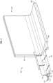
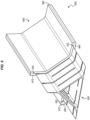
- FIG. 1 illustrates tooling 100 for a hybrid composite part in an illustrative example.
- a hybrid composite part is a part that includes a composite material (e.g., a fiber reinforced composite material, such as CFRP) that surrounds a core made from a different material.
- CFRP fiber reinforced composite material
- Tooling 100 comprises any suitable rigid material that defines a shape for a preform of fiber reinforced material and is capable of withstanding heat and temperature applied during hardening of the fiber reinforced material (e.g., a curing temperature of roughly 500° F (260° C) for thermoset parts and roughly 900° F (480° C) for thermoplastic parts). Tooling 100 may also be referred to herein as a "tool.” Tooling 100 becomes integral with the fiber reinforced material during hardening.
- tooling 100 may be made from sheets of a core material such as a metal (e.g., titanium, aluminum), an additive manufacturing material applied via an additive manufacturing process, etc.
- the core material may be lighter by volume than solid CFRP. This lightness provides a technical benefit by reducing weight, which results in less fuel costs if the resulting composite part is used in a vehicle.
- tooling 100 may have an elastic modulus between one half and one and a half times an elastic modulus of the fiber reinforced material. In this manner, when the tooling 100 forms part of a hybrid composite part, elastic deflection of the hybrid composite part will not damage or break the bond between tooling 100 and any fiber reinforced portions of the hybrid composite part.
- Tooling 100 includes a body 110 with sides (i.e., side 120, side 130, and side 140). While body 110 is elongated in this example, body 110 may be formed according to any suitable shape in further examples. Each side of tooling 100 is shaped according to a contour. In this example, side 120 is shaped according to contour 122 (which is arcuate), side 130 is shaped according to contour 132 (which is arcuate), and side 140 is shaped according to contour 142 (which is flat). These contours define the shape which will be taken by a preform disposed (e.g., placed or laid-up) atop tooling 100.
- the sides of tooling 100 are complementary to the sides of a cavity that will exist within a laminate that will be disposed at tooling 100.
- Side 130 and side 120 are radiused due to bends that will exist in the laminate, while side 140 is flat.
- cut-outs 160 are distributed along a length of body 110, resulting in flanges 112, flanges 114, and flanges 116 disposed where the sides join together. Cut-outs 160 increase an amount of flexibility of tooling 100, allowing tooling 100 to bend more readily along its lengthwise axis L. The cut-outs specifically increase flexibility by reducing an amount of material at specific locations. This reduces resistance to flexing at those locations, because the locations have reduced flexural stiffness/reduced rigidity.
- Cut-outs may, for example, extend from half to an entire height of a flange, may be several millimeters across, and may be disposed at intervals ranging from every few centimeters or every few meters, depending on the amount of flexion desired. For straight tooling 100 that will not experience dynamic bending loads, no cut-outs are needed. While referred to as "cut-outs,” cut-outs 160 need not be physically cut out of body 110, but rather may comprise gaps where material is not placed during fabrication of body 110.
- Tooling 100 also includes void 150 in this example.
- Void 150 is a space through which cabling or electromagnetic signals may be conveyed.
- void 150 may facilitate non-destructive inspection of tooling 100 via ultrasonic waves.
- tooling 100 Illustrative details of the operation of tooling 100 will be discussed with regard to FIG. 2 . Assume, for this example, that tooling 100 has been fabricated via a mold or via additive manufacturing processes.
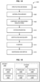
- FIG. 2 is a flowchart illustrating a method 200 for utilizing tooling during fabrication of a hybrid composite part in an illustrative example.
- the steps of method 200 are described with reference to tooling 100 of FIG. 1 , but those skilled in the art will appreciate that method 200 may be performed for other tooling that will be integrated into a hybrid composite part.
- the steps of the flowcharts described herein are not all inclusive and may include other steps not shown. The steps described herein may also be performed in an alternative order.
- tooling 100 is selected, having a body and sides made of a core material with a desired shape and size.
- Tooling 100 may be selected, for example, based on its shape and a desired shape of a hybrid composite part to be fabricated, in accordance with a predetermined schedule, etc.
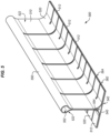
- a preform of fiber reinforced material (e.g., preform 350 of FIG. 3 ) is disposed so that it surrounds the body 110 (e.g., surrounding the sides of tooling 100).
- a lamina assembly 300 comprising the preform 350 and the tooling 100.
- preform 350 comprises sheet 360, sheet 370, and sheet 380 of CFRP which surround the perimeter of tooling 100. That is, preform 350 is disposed (e.g., laid-up, placed after being laid-up flat elsewhere, etc.) atop side 120, side 130, and side 140 of tooling 100, respectively. Because tooling 100 is rigid, it defines the contours of the sheets of preform 350.
- Tooling 100 also fills internal corners 352 of preform 350, and receives stresses via internal corners 352. This enhances the structural strength of a resulting hybrid composite part, by increasing the ability of that part to resist delamination when experiencing stress. For example, because tooling 100 tapers within preform 350, it exhibits an increased amount of interfacial contact between tooling 100 and preform 350. Thus, the taper (e.g., at a rate between five to one and one hundred to one), provides a technical effect in the form or increasing bond strength based on the increased amount of interfacial contact between tooling 100 and preform 350. The increased amount of interfacial contact increases an area along which tooling 100 and preform 350 are bonded, which in turn increases bond strength between these components. While a portion of tooling 100 is illustrated as projecting outward from preform 350 in FIG. 3 , it will be appreciated that such portions are for illustrative and contextual purposes only, no portions of tooling 100 need project outward from preform 350.
- the tooling described herein is also shaped to provide support against crushing loads, because it increases an amount of material within the hybrid composite part that resists crushing forces.
- the tooling described herein may even provide limited structural support with regard to tensile bending loads at the hybrid composite part.
- preform 350 and tooling 100 may be placed into a vacuum bag for compaction and curing, or may be placed into a mandrel for compaction and curing.
- tooling 100 and preform 350 are heated. This may initiate a curing or other hardening process for resin within preform 350.
- step 208 the tooling 100 is co-bonded to the fiber reinforced material within the lamina assembly 300. This may come about as a result of the hardening process of step 206.
- preform 350 and tooling 100 are hardened into a hybrid composite part that includes tooling 100 as an integral component.
- the heating in step 206 cures resin within preform 350. This action of heating therefore co-bonds the preform 350 to tooling 100. That is, resin within tooling 100 hardens and bonds to the core material that tooling 100 is made from.
- cooling of preform 350 (after preform 350 has reached a molten state) causes preform 350 to solidify and harden around tooling 100. Because tooling 100 is rigid, preform 350 will not collapse during the consolidating and/or hardening process. If tooling 100 was absent or not rigid, then the potential for collapse of preform 350, and any cavities defined by preform 350, would be substantial.
- Method 200 provides a technical benefit by providing tooling 100 which both defines a shape for, and enhances the strength of, a composite part.
- tooling 100 may enhance the strength of internal corners at a resulting hybrid composite part. This means stresses received while bearing load at the hybrid composite part are transferred from an exterior of the hybrid composite part (i.e., a fiber reinforced portion) to the tooling, which forms a core of the hybrid composite part. Depending on the dimensions and material properties of the hybrid composite part, this facilitates elastic deformation of the hybrid composite part in a predefined and desired manner in response to an applied stress.
- tooling 100 is integrated into the preform, tooling 100 does not have to be removed from the preform (which may be a difficult process) after hardening of the preform. This saves labor related to removing the tooling, and prevents the composite part from being damaged by any removal process.
- FIG. 3 which has been described above with respect to the method of FIG. 2 , illustrates a lamina assembly 300 in the form of a blade stiffener or inverted "T.”
- FIG. 3 illustrates but one of many potential versions of blade stiffeners that may be utilized according to the examples described herein.
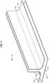
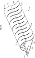
- FIG. 4 is an exploded view of tooling 400 made from multiple sheets of core material in an illustrative example.
- Tooling 400 may be utilized as a mandrel upon which preform 350 is disposed and hardened.
- tooling 400 may be utilized in a similar manner to tooling 100.
- the sheets of core material are welded or bonded together to form the tooling 400, and cut-outs may then be added to the tooling 400 at a later stage.
- sheet 420 is shaped according to contour 122
- sheet 430 is shaped according to contour 132
- sheet 440 is shaped according to contour 142. These contours are complementary to radii of bends found in sheet 360 and sheet 370 of preform 350.
- the fabrication techniques for creating tooling 100 discussed in FIG. 4 may be used as an alternative to additive manufacturing techniques, if desired.
- FIGS. 5-12 illustrate additional tooling in combination with preforms in illustrative examples.
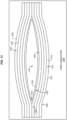
- FIG. 5 illustrates tooling 500 in an illustrative example.
- tooling 500 includes a side 520, which forms a top following a contour 522.
- Tooling 500 also includes a side 540, which forms a bottom following a contour 542.
- Contour 522 defines rounded section 550, which surrounds a void 552. Cut-outs 562 and cut-outs 564 subdivide a periphery 510 of tooling 500 into flanges 512.
- Tooling 500 may provide enhanced structural strength for composite parts having complex geometries.
- tooling 500 may be utilized in order to define a path for cabling or electromagnetic signaling to pass through in a resulting hybrid composite part.
- void 552 is used for this purpose.
- Tooling 500 may be utilized for supporting a laminate that will be hardened into a blade stiffener. One sheet of the laminate may be bent around side 520, while another sheet of the laminate may be placed below side 540. Tooling 500 may support these sheets during hardening, enforcing a desired shape onto the laminate and enabling one or more voids such as void 552 and void 554 to be formed as desired.
- FIGS. 6-7 illustrate tooling for a hybrid composite part that has a substantial vertical dimension.
- FIGS. 8-9 illustrate tooling for a hybrid composite part having a triangular cross-section
- FIGS. 10-12 illustrate tooling for reinforcing a hybrid composite part having a D-shaped cross-section.
- FIGS. 6-7 illustrate a similar blade stiffener configuration to that depicted in FIG. 3 , but with tooling that includes a larger vertical projection.
- This enables greater support/strengthening of a vertical portion of the blade stringer, by increasing an amount of interfacial contact along the vertical portion of the blade stringer between the laminate and the tooling.
- the interfacial strength of bonding between the tooling and a laminate is increased, which in turn increases the resistance of a resulting hybrid composite part to delamination.
- tooling 600 includes a vertical extension to enhance the strength of a resulting hybrid composite part.
- Tooling 600 includes a body 610 having side 620 (following contour 622), side 630 (following contour 632), and side 640 (following contour 642).
- Tooling 600 surrounds a void 650, and has flanges 612, flanges 614, and flanges 616 that are formed by cut-outs 662 and cut-outs 664.
- tooling 600 provides a shape for preform 750 at layup 700.
- Tooling 600 also provides enhanced structural strength at internal corners 752 of preform 750, because it supports these internal corners 752.
- Tooling 600 may also provide a geometric structural advantage, by increasing a distance of internal corners 752 from a center 790 of the hybrid composite part. This increased distance reduces peel/separation forces experienced by the hybrid composite part.
- tooling 800 defines a large triangular cavity (i.e., void 850).
- Tooling 800 includes a body 810 having side 820 (following contour 822), side 830 (following contour 832), and side 840 (following contour 842).
- Tooling 800 surrounds a void 850, and has flanges 812, flanges 814, and flanges 816 that are formed by cut-outs 862 and cut-outs 864.
- tooling 800 provides a shape for preform 950 at layup 900.
- Tooling 800 also provides enhanced structural strength at internal corners 952 of preform 950, in a similar manner to tooling 600 of FIG. 6 discussed above. Internal corners 952 are formed by intersections between sheet 960, sheet 970, and sheet 980 of preform 950.
- tooling 1000 is formed according to a D-shape.
- tooling 1000 includes a body 1010 having side 1020 (following contour 1022), and side 1040 (following contour 1042).
- Tooling 1000 surrounds a void 1050, and has flanges 1012, flanges 614, and flanges 616 that are formed by cut-outs 1062.
- FIG. 11 tooling 1000 provides a shape for preform 1150 at layup 1100.
- Tooling 1000 also provides enhanced structural strength at internal corners 1152 of preform 1150, in a similar manner to tooling 600 of FIG. 6 discussed above. Internal corners 1152 are formed by intersections between sheet 1160 and sheet 1170 of preform 1150.
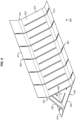
- FIG. 12 illustrates a further example where tooling 1000 may be utilized.
- a first set 1210 of tooling 1000 located on the right side of layup 1200, provides support for a series of D-shaped portions of a preform 1250.
- a second set 1220 of tooling 100 is vertically inverted with respect to first set 1210, and provides support for another series of D-shape portions at the preform 1250.
- FIG. 13 is a block diagram of a hybrid composite part 1300 in an illustrative example.
- hybrid composite part 1300 includes tooling 1330, which is made from a material 1360 such as titanium and surrounds a void 1370.
- a preform 1350 is disposed onto a surface 1332 of tooling 1330.
- Preform 1350 includes ply 1310 (comprising resin 1312 and fibers 1314).
- Preform 1350 also includes ply 1320 (comprising resin 1322 and fibers 1324).
- Tooling 1330 provides a rigid structure upon which preform 1350 may be placed and hardened.
- tooling 1330 increases a strength of internal corners at preform 1350, for example by increasing a radius of internal corners at preform 1350. That is, a radius 1334 of tooling 1330 is greater than a radius which would be formed by an internal corner 1352 at an intersection between ply 1320 and ply 1310.
- method 1400 may include specification and design 1404 of the aircraft 1402 and material procurement 1406.
- component and subassembly manufacturing 1408 and system integration 1410 of the aircraft 1402 takes place.
- the aircraft 1402 may go through certification and delivery 1412 in order to be placed in service 1414.
- the aircraft 1402 is scheduled for routine work in maintenance and service 1416 (which may also include modification, reconfiguration, refurbishment, and so on).
- Apparatus and methods embodied herein may be employed during any one or more suitable stages of the production and service described in method 1400 (e.g., specification and design 1404, material procurement 1406, component and subassembly manufacturing 1408, system integration 1410, certification and delivery 1412, service 1414, maintenance and service 1416) and/or any suitable component of aircraft 1402 (e.g., airframe 1418, systems 1420, interior 1422, propulsion system 1424, electrical system 1426, hydraulic system 1428, environmental system1430).
- any suitable component of aircraft 1402 e.g., airframe 1418, systems 1420, interior 1422, propulsion system 1424, electrical system 1426, hydraulic system 1428, environmental system1430.
- a system integrator may include without limitation any number of aircraft manufacturers and major-system subcontractors; a third party may include without limitation any number of vendors, subcontractors, and suppliers; and an operator may be an airline, leasing company, military entity, service organization, and so on.
- the aircraft 1402 produced by method 1400 may include an airframe 1418 with a plurality of systems 1420 and an interior 1422.
- systems 1420 include one or more of a propulsion system 1424, an electrical system 1426, a hydraulic system 1428, and an environmental system 1430. Any number of other systems may be included.
- an aerospace example is shown, the principles of the disclosure may be applied to other industries, such as the automotive industry.
- apparatus and methods embodied herein may be employed during any one or more of the stages of the production and service described in method 1400.
- components or subassemblies corresponding to component and subassembly manufacturing 1408 may be fabricated or manufactured in a manner similar to components or subassemblies produced while the aircraft 1402 is in service.
- one or more apparatus examples, method examples, or a combination thereof may be utilized during the subassembly manufacturing 1408 and system integration 1410, for example, by expediting or substantially expediting assembly of or reducing the cost of an aircraft 1402.
- one or more of apparatus examples, method examples, or a combination thereof may be utilized while the aircraft 1402 is in service, for example and without limitation during the maintenance and service 1416.
- the techniques and systems described herein may be used for material procurement 1406, component and subassembly manufacturing 1408, system integration 1410, service 1414, and/or maintenance and service 1416, and/or may be used for airframe 1418 and/or interior 1422.
- systems 1420 including, for example, propulsion system 1424, electrical system 1426, hydraulic system 1428, and/or environmental system 1430.
- a part comprises a portion of airframe 1418, and is manufactured during component and subassembly manufacturing 1408.
- the part may then be assembled into an aircraft in system integration 1410, and then be utilized in service 1414 until wear renders the part unusable. Then, in maintenance and service 1416, the part may be discarded and replaced with a newly manufactured part.
- Inventive components and methods may be utilized throughout component and subassembly manufacturing 1408 in order to manufacture new parts.
- control elements e.g., electrical or electronic components
- a processor implementing software
- a processor implementing firmware or some combination of these.
- an element may be implemented as dedicated hardware.
- Dedicated hardware elements may be referred to as "processors", “controllers”, or some similar terminology.
- the functions may be provided by a single dedicated processor, by a single shared processor, or by a plurality of individual processors, some of which may be shared.
- processor or “controller” should not be construed to refer exclusively to hardware capable of executing software, and may implicitly include, without limitation, digital signal processor (DSP) hardware, a network processor, application specific integrated circuit (ASIC) or other circuitry, field programmable gate array (FPGA), read only memory (ROM) for storing software, random access memory (RAM), non-volatile storage, logic, or some other physical hardware component or module.
- DSP digital signal processor
- ASIC application specific integrated circuit
- FPGA field programmable gate array
- ROM read only memory
- RAM random access memory
- non-volatile storage logic, or some other physical hardware component or module.
- a control element may be implemented as instructions executable by a processor or a computer to perform the functions of the element.
- instructions are software, program code, and firmware.
- the instructions are operational when executed by the processor to direct the processor to perform the functions of the element.
- the instructions may be stored on storage devices that are readable by the processor. Some examples of the storage devices are digital or solid-state memories, magnetic storage media such as a magnetic disks and magnetic tapes, hard drives, or optically readable digital data storage media.
Landscapes
- Engineering & Computer Science (AREA)
- Mechanical Engineering (AREA)
- Chemical & Material Sciences (AREA)
- Composite Materials (AREA)
- Manufacturing & Machinery (AREA)
- Materials Engineering (AREA)
- Physics & Mathematics (AREA)
- Optics & Photonics (AREA)
- Moulding By Coating Moulds (AREA)
Description
- The disclosure relates to the field of fabrication, and in particular, to composite parts.
- Composite parts, such as Carbon Fiber Reinforced Polymer (CFRP) parts, are utilized to provide structural strength for vehicles as well as for structures. During fabrication, a composite stringer or other structural support may be created by laying up sheets of fiber in a desired shape. This may result in a "C" shaped cross-section, an "I" shaped cross-section, a hat shaped cross-section, or others. When sheets of fiber are laid up together and contoured to form a desired shape, gaps may form in the bend radius and/or at joints between the sheets. It is undesirable to have gaps in the finished structure, thus a challenge remains in filling these gaps.
- Therefore, it would be desirable to have a method and apparatus that take into account at least some of the issues discussed above, as well as other possible issues.
-
US 2017/095983 , in accordance with its abstract, states "a contoured composite laminate stiffener is fabricated by assembling a substantially flat composite laminate charge and forming the charge into a substantially straight stiffener having a desired cross sectional shape. A contour is formed in the stiffener which has an inside radius and an outside radius. Ply wrinkling is substantially eliminated by reducing compression strain on the inside radius as the stiffener as being contoured". -
US 2014/186588 , in accordance with its abstract, states "processes for fabricating an integrated fiber-reinforced cured resin-composite panel structure include forming a panel preform assembly by (i) positioning pre-cured fiber-reinforced resin-composite tubular stiffeners onto an uncured base skin, and (ii) applying uncured fiber-reinforced resin-composite overlapping layers onto the pre-cured stiffeners so that at least lateral edges of the overlapping layers are laminated to a corresponding region of the base sheet; and thereafter curing the fiber-reinforced resin-composite base skin and overlapping layers to thereby form an integrated composite panel structure". -
US 2015/099096 , in accordance with its abstract, states "an apparatus including a first thermoset layer that includes a first fibrous material embedded in a first thermoset matrix. The apparatus also includes a second thermoset layer that includes a second fibrous material embedded in a second thermoset matrix. The second thermoset layer is coupled to the first thermoset layer to form a joint. Further, a gap is defined between the first thermoset layer and the second thermoset layer. The apparatus also includes a thermoplastic filler that is made from a thermoplastic material. The thermoplastic filler is positioned within the gap". -
GB2105254 -
US 2006/108057 , in accordance with its abstract, states "an aircraft stringer lay-up assembly is provided comprising a contoured curing block and a first mandrel element positioned thereon. The first mandrel assembly includes a first bar assembly having a plurality of rigidity reducing first slots formed along a first mandrel length. The plurality of rigidity reducing first slots protruding partially through a first mandrel depth of the first mandrel element to allow the first bar assembly to conform to the contoured curing block. A composite ply assembly is laid up onto the first mandrel element and cured while conformed to said contoured curing block such that a contoured composite stringer element is generated". - According to independent claim 1, there is provided a hybrid composite part, for example an aircraft part, the hybrid composite part comprising: a tool; and fiber reinforced material that surrounds the tool and is co-bonded with the tool, wherein the tool surrounds a void, and wherein the tool includes cut-outs that are distributed along its length and wherein the cut-outs increase an amount of flexibility of the tool.
- According to claim 15, there is provided a method of fabricating a portion of an aircraft using the hybrid composite part described above.
- According to claim 14, there is provided a portion of an aircraft comprising a hybrid composite part as described above.
- Examples described herein provide tooling that defines a shape for a preform during layup, and is made integral with the preform during hardening of the preform into a hybrid composite part. Thus, while the tooling is originally used to define a shape for laying up unhardened fiber reinforced material, the tooling is co-bonded with the fiber reinforced portions during the hardening process. This results in a hybrid composite part made of both the tooling and fiber reinforced material. The tooling may form the core of the hybrid composite part and structurally reinforces composite material within the hybrid composite part. The tooling therefore acts as a forming tool for the hybrid composite part and also as a component that enhances structural strength. This provides an advantage in the form of enhanced ease of manufacture as well as increased strength for composite parts.
- One example not falling within the scope of the claims, but useful for understanding the disclosure is a method for fabricating a composite part. The method includes selecting a tool with sides made of a core material in a desired size and shape, disposing a preform of a fiber reinforced material that surrounds the tool, resulting in a lamina assembly comprising the preform and the tool, heating the tool and the preform, co-bonding the tool to the fiber reinforced material within the lamina assembly, and hardening the preform and the tool into a hybrid composite part.
- A further example not falling within the scope of the claims, but useful for understanding the disclosure is a non-transitory computer readable medium embodying programmed instructions which, when executed by a processor, are operable for performing a method for fabricating a composite part. The method includes selecting a tool with sides made of a core material in a desired size and shape, disposing a preform of a fiber reinforced material that surrounds the tool, resulting in a lamina assembly comprising the preform and the tool, heating the tool and the preform, co-bonding the tool to the fiber reinforced material within the lamina assembly, and hardening the preform and the tool into a hybrid composite part.
- An additional example not falling within the scope of the claims, but useful for understanding the disclosure is a manufacture in the form of a hybrid composite part. The manufacture includes a tool, and fiber reinforced material that surrounds the tool and is co-bonded with the tool. The tool surrounds a void.
- A still-further example not falling within the scope of the claims, but useful for understanding the disclosure is an apparatus in the form of a hybrid composite part. The apparatus includes tooling comprising a body with sides made of a core material in a desired size and shape, and is made of a material that remains rigid at a curing temperature for a fiber reinforced material. The tooling also includes one or more flanges disposed where the sides are joined together. The hybrid composite part also includes a void within the body that proceeds along an axial length of the body.
- Further, the disclosure comprises the following examples useful for understanding the disclosed embodiments:
In a first example not falling within the scope of the claims, there is described a method for fabricating a composite part, the method comprising: selecting a tool with sides made of a core material in a desired size and shape; disposing a preform of a fiber reinforced material that surrounds the tool, resulting in a lamina assembly comprising the preform and the tool; heating the tool and the preform; co-bonding the tool to the fiber reinforced material within the lamina assembly; and hardening the preform and the tool into a hybrid composite part. - Advantageously, the method of the first example further comprises: forming the tool such that a body of the tool includes a void.
- Advantageously, the method of the first example further comprises: fabricating the tool from sheets of metal.
- Advantageously, the method of the first example further comprises: fabricating the tool via additive manufacturing.
- Advantageously, the method of the first example further comprises: transferring stresses during service of the hybrid composite part from a fiber reinforced portion of the hybrid composite part to the tool.
- Advantageously, the method of the first example further comprises: elastically deforming the hybrid composite part while maintaining a bond between the tool and a fiber reinforced portion of the hybrid composite part, in response to an applied stress.
- In a second example not falling within the scope of the claims, there is described a portion of an aircraft assembled according to the method of the first example.
- In a third example not falling within the scope of the claims, there is described a non-transitory computer readable medium embodying programmed instructions which, when executed by a processor, are operable for performing a method for fabricating a composite part, the method comprising: selecting a tool with sides made of a core material in a desired size and shape; disposing a preform of a fiber reinforced material that surrounds the tool, resulting in a lamina assembly comprising the preform and the tool; heating the tool and the preform; co-bonding the tool to the fiber reinforced material within the lamina assembly; and hardening the preform and the tool into a hybrid composite part.
- Advantageously, in the medium of the third example, the method further comprises: forming the tool such that a body of the tool includes a void.
- Advantageously, in the medium of the third example, the method further comprises:
fabricating the tooling from sheets of metal. - Advantageously, in the medium of the third example, the method further comprises: fabricating the tool via additive manufacturing.
- Advantageously, in the medium of the third example, the method further comprises: transferring stresses during service of the hybrid composite part from a fiber reinforced portion of the hybrid composite part to the tool.
- Advantageously, in the medium of any the third example, the method further comprises: elastically deforming the hybrid composite part while maintaining a bond between the tool and a fiber reinforced portion of the hybrid composite part, in response to an applied stress.
- In a fourth example not falling within the scope of the claims, there is described a portion of an aircraft assembled according to the method defined by the instructions stored on the computer readable medium of the third example.
- In a fifth example not falling within the scope of the claims, there is described a manufacture in the form of a hybrid composite part, the manufacture comprising: a tool; and fiber reinforced material that surrounds the tool and is co-bonded with the tool, the tool surrounds a void.
- Advantageously, in the manufacture of the fifth example the tool forms a core of the hybrid composite part.
- Advantageously, in the manufacture of the fifth example the tool includes cut-outs that are distributed along its length.
- Advantageously, in the manufacture of the fifth example the cut-outs increase an amount of flexibility of the tool.
- Advantageously, in the manufacture of the fifth example the tool is made from a material having an elastic modulus between one half and one and a half times an elastic modulus of the fiber reinforced material.
- Advantageously, in the manufacture of the fifth example the fiber reinforced material is Carbon Fiber Reinforced Polymer (CFRP).
- Advantageously, in the manufacture of the fifth example the tool is made from a material that is lighter than Carbon Fiber Reinforced Polymer (CFRP).
- Advantageously, in the manufacture of the fifth example wherein tool remains rigid at a curing temperature of the fiber reinforced material.
- In a sixth example not falling within the scope of the claims, there is described fabricating a portion of an aircraft using the manufacture of the fifth example.
- In a seventh example not falling within the scope of the claims, there is described an apparatus in the form of a hybrid composite part, comprising: tooling comprising: a body with sides made of a core material in a desired size and shape, and is made of a material that remains rigid at a curing temperature for a fiber reinforced material; one or more flanges disposed where the sides are joined together; and a void within the body that proceeds along an axial length of the body.
- Advantageously, the apparatus of the seventh example comprises: cut-outs disposed at each side of the body that reduce a rigidity of the body.
- Advantageously, in the apparatus of the seventh example each side of the body follows a contour.
- Advantageously, in the apparatus of the seventh example the flanges are tapered.
- In an eighth example, not falling within the scope of the claims, there is described a method of fabricating a composite part using a tool with sides made of a core material in a desired size and shape, the method comprising: disposing a preform of a fiber reinforced material that surrounds the tool, resulting in a lamina assembly comprising the preform and the tool; heating the tool and the preform; co-bonding the tool to the fiber reinforced material within the lamina assembly; and hardening the preform and the tool into a hybrid composite part.
- Advantageously, in the method of the eighth example the tool such comprises a body that includes a void.
- Advantageously, in the method of the eighth example the tool is fabricated from sheets of metal.
- Advantageously, in the method of the eighth example the tool is fabricated by additive manufacturing.
- Advantageously, the method of the eighth example further comprises: transferring stresses, for example during service of the hybrid composite part, from a fiber reinforced portion of the hybrid composite part to the tool.
- Advantageously, the method of the eighth example further comprises: elastically deforming the hybrid composite part while maintaining a bond between the tool and a fiber reinforced portion of the hybrid composite part, in response to an applied stress.
- In a ninth example not falling within the scope of the claims, there is described a method of fabricating and using a composite part, comprising: the method of fabricating the composite part of the eighth example; and transferring stresses during service of the hybrid composite part from a fiber reinforced portion of the hybrid composite part to the tool.
- In a tenth example not falling within the scope of the claims, there is described a method of fabricating and using a composite part, comprising: the method of fabricating the composite part of the eighth example; and elastically deforming the hybrid composite part while maintaining a bond between the tool and a fiber reinforced portion of the hybrid composite part, in response to an applied stress.
- In an eleventh example not falling within the scope of the claims, there is described a portion of an aircraft assembled according to the method of the eighth, ninth or tenth examples.
- In a twelfth example not falling within the scope of the claims, there is described an aircraft including a part assembled according to the method of the eighth, ninth or tenth examples.
- In a thirteenth example not falling within the scope of the claims, there is described a computer program comprising computer instructions which, when executed by a computer processor of a computer system, cause the computer system to perform the method of the eighth, ninth or tenth examples
- In a fourteenth example not falling within the scope of the claims, there is described a non-transitory computer readable medium having stored therein the computer program of the thirteenth example.
- In a fifteenth example not falling within the scope of the claims, there is described a computer system comprising a computer processor and a memory having stored therein computer instructions which, when executed by the computer processor, cause the computer system to perform the method of the eighth, ninth or tenth examples.
- In a sixteenth example not falling within the scope of the claims, there is described an apparatus for fabricating a composite part comprising the computer system of the fifteenth example.
- In a seventeenth example, there is described a hybrid composite part, the hybrid composite part comprising: a tool; and fiber reinforced material that surrounds the tool and is co-bonded with the tool, and wherein the tool surrounds a void. In the hybrid composite part of the seventeenth example the tool includes cut-outs that are distributed along its length.In the hybrid composite part of the seventeenth example the cut-outs increase an amount of flexibility of the tool.
- Advantageously, in the hybrid composite part of the seventeenth example the tool forms a core of the hybrid composite part.
- Advantageously, in the hybrid composite part of the seventeenth example the tool is made from a material having an elastic modulus between one half and one and a half times an elastic modulus of the fiber reinforced material.
- Advantageously, in the hybrid composite part of the seventeenth example the fiber reinforced material is Carbon Fiber Reinforced Polymer (CFRP).
- Advantageously, in the hybrid composite part of the seventeenth example the tool is made from a material that is lighter than Carbon Fiber Reinforced Polymer (CFRP).
- Advantageously, in the hybrid composite part of the seventeenth example the tool remains rigid at a curing temperature of the fiber reinforced material.
- In an eighteenth example, there is described fabricating a portion of an aircraft using the hybrid composite part of the seventeenth example.
- In a nineteenth example not falling within the scope of the claims, there is described a hybrid composite part, comprising: tooling comprising: a body with sides made of a core material in a desired size and shape, and is made of a material that remains rigid at a curing temperature for a fiber reinforced material; one or more flanges disposed where the sides are joined together; and a void within the body that proceeds along an axial length of the body.
- Advantageously, the apparatus of the nineteenth example further comprises: cut-outs disposed at each side of the body that reduce a rigidity of the body.
- Advantageously, in the apparatus of the nineteenth example each side of the body follows a contour.
- Advantageously, in the apparatus of the nineteenth example the flanges are tapered.
- Other illustrative examples (e.g., methods and computer-readable media relating to the foregoing examples) may be described below and in the dependent claims.
- Some examples of the present disclosure are now described, by way of example only, and with reference to the accompanying drawings. The same reference number represents the same element or the same type of element on all drawings.
-
FIG. 1 illustrates tooling for a hybrid composite part in an illustrative example -
FIG. 2 is a flowchart illustrating a method for utilizing tooling during fabrication of a hybrid composite part in an illustrative example. -
FIG. 3 is a perspective view illustrating layup of a preform that conforms with contours defined by internal tooling in an illustrative example. -
FIG. 4 is an exploded view of tooling made from multiple sheets of core material in an illustrative example. -
FIGS. 5-12 illustrate additional tooling and preforms in illustrative examples. -
FIG. 13 is a block diagram of a hybrid composite part in an illustrative example. -
FIG. 14 is a flow diagram of aircraft production and service methodology in an illustrative example. -
FIG. 15 is a block diagram of an aircraft in an illustrative example. - The figures and the following description provide specific illustrative examples of the disclosure. It will thus be appreciated that those skilled in the art will be able to devise various arrangements that, although not explicitly described or shown herein, embody the principles of the disclosure and are included within the scope of the disclosure as set out in the claims.
- Furthermore, any examples described herein are intended to aid in understanding the principles of the disclosure, and are to be construed as being without limitation to such specifically recited examples and conditions.
- Composite parts, such as Carbon Fiber Reinforced Polymer (CFRP) parts, are initially laid-up in multiple layers that together are referred to as a preform. Individual fibers within each layer of the preform are aligned parallel with each other, but different layers may exhibit different fiber orientations in order to increase the strength of the resulting composite along different dimensions. The preform may include a viscous resin that solidifies in order to harden the preform into a composite part (e.g., for use in an aircraft). Carbon fiber that has been impregnated with an uncured thermoset resin or a thermoplastic resin is referred to as "prepreg". Other types of carbon fiber include "dry fiber" which has not been impregnated with thermoset resin but may include a tackifier or binder. Dry fiber may be infused with resin prior to curing. For thermoset resins, the hardening is a one-way process referred to as curing, while for thermoplastic resins, the resin may reach a viscous form if it is re-heated.
-
FIG. 1 illustrates tooling 100 for a hybrid composite part in an illustrative example. As used herein, a "hybrid composite part" is a part that includes a composite material (e.g., a fiber reinforced composite material, such as CFRP) that surrounds a core made from a different material. - Tooling 100 comprises any suitable rigid material that defines a shape for a preform of fiber reinforced material and is capable of withstanding heat and temperature applied during hardening of the fiber reinforced material (e.g., a curing temperature of roughly 500° F (260° C) for thermoset parts and roughly 900° F (480° C) for thermoplastic parts). Tooling 100 may also be referred to herein as a "tool." Tooling 100 becomes integral with the fiber reinforced material during hardening. For example, tooling 100 may be made from sheets of a core material such as a metal (e.g., titanium, aluminum), an additive manufacturing material applied via an additive manufacturing process, etc. In further examples, the core material may be lighter by volume than solid CFRP. This lightness provides a technical benefit by reducing weight, which results in less fuel costs if the resulting composite part is used in a vehicle.
- In still further examples, it may be desirable for the elastic modulus and/or coefficient of thermal expansion of the core material to match or substantially match that of the rest of the composite part (e.g., in order to prevent internal stresses within the completed, cured part that would result from mismatched elastic moduli). In such examples, tooling 100 may have an elastic modulus between one half and one and a half times an elastic modulus of the fiber reinforced material. In this manner, when the
tooling 100 forms part of a hybrid composite part, elastic deflection of the hybrid composite part will not damage or break the bond betweentooling 100 and any fiber reinforced portions of the hybrid composite part. - Tooling 100 includes a
body 110 with sides (i.e.,side 120,side 130, and side 140). Whilebody 110 is elongated in this example,body 110 may be formed according to any suitable shape in further examples. Each side oftooling 100 is shaped according to a contour. In this example,side 120 is shaped according to contour 122 (which is arcuate),side 130 is shaped according to contour 132 (which is arcuate), andside 140 is shaped according to contour 142 (which is flat). These contours define the shape which will be taken by a preform disposed (e.g., placed or laid-up) atoptooling 100. Conceptualized another way, the sides oftooling 100 are complementary to the sides of a cavity that will exist within a laminate that will be disposed attooling 100.Side 130 andside 120 are radiused due to bends that will exist in the laminate, whileside 140 is flat. - In this example, cut-
outs 160 are distributed along a length ofbody 110, resulting inflanges 112,flanges 114, andflanges 116 disposed where the sides join together. Cut-outs 160 increase an amount of flexibility oftooling 100, allowingtooling 100 to bend more readily along its lengthwise axis L. The cut-outs specifically increase flexibility by reducing an amount of material at specific locations. This reduces resistance to flexing at those locations, because the locations have reduced flexural stiffness/reduced rigidity. Cut-outs may, for example, extend from half to an entire height of a flange, may be several millimeters across, and may be disposed at intervals ranging from every few centimeters or every few meters, depending on the amount of flexion desired. Forstraight tooling 100 that will not experience dynamic bending loads, no cut-outs are needed. While referred to as "cut-outs," cut-outs 160 need not be physically cut out ofbody 110, but rather may comprise gaps where material is not placed during fabrication ofbody 110. - This may be beneficial in environments where
tooling 100 will experience flexion after it has been integrated into a hybrid composite part. This flexion may also allow fortooling 100 to bend to accommodate joggles, bends or twists in a cavity at the laminate. Tooling 100 also includes void 150 in this example.Void 150 is a space through which cabling or electromagnetic signals may be conveyed. For example, void 150 may facilitate non-destructive inspection oftooling 100 via ultrasonic waves. - Illustrative details of the operation of
tooling 100 will be discussed with regard toFIG. 2 . Assume, for this example, that tooling 100 has been fabricated via a mold or via additive manufacturing processes. -
FIG. 2 is a flowchart illustrating amethod 200 for utilizing tooling during fabrication of a hybrid composite part in an illustrative example. The steps ofmethod 200 are described with reference to tooling 100 ofFIG. 1 , but those skilled in the art will appreciate thatmethod 200 may be performed for other tooling that will be integrated into a hybrid composite part. The steps of the flowcharts described herein are not all inclusive and may include other steps not shown. The steps described herein may also be performed in an alternative order. - In
step 202, tooling 100 is selected, having a body and sides made of a core material with a desired shape and size. Tooling 100 may be selected, for example, based on its shape and a desired shape of a hybrid composite part to be fabricated, in accordance with a predetermined schedule, etc. - In
step 204, a preform of fiber reinforced material (e.g., preform 350 ofFIG. 3 ) is disposed so that it surrounds the body 110 (e.g., surrounding the sides of tooling 100). This results in alamina assembly 300 comprising thepreform 350 and thetooling 100. For example, as shown inlamina assembly 300 ofFIG. 3 , preform 350 comprisessheet 360,sheet 370, andsheet 380 of CFRP which surround the perimeter oftooling 100. That is,preform 350 is disposed (e.g., laid-up, placed after being laid-up flat elsewhere, etc.) atopside 120,side 130, andside 140 oftooling 100, respectively. Becausetooling 100 is rigid, it defines the contours of the sheets ofpreform 350. Tooling 100 also fillsinternal corners 352 ofpreform 350, and receives stresses viainternal corners 352. This enhances the structural strength of a resulting hybrid composite part, by increasing the ability of that part to resist delamination when experiencing stress. For example, because tooling 100 tapers withinpreform 350, it exhibits an increased amount of interfacial contact betweentooling 100 andpreform 350. Thus, the taper (e.g., at a rate between five to one and one hundred to one), provides a technical effect in the form or increasing bond strength based on the increased amount of interfacial contact betweentooling 100 andpreform 350. The increased amount of interfacial contact increases an area along whichtooling 100 and preform 350 are bonded, which in turn increases bond strength between these components. While a portion oftooling 100 is illustrated as projecting outward frompreform 350 inFIG. 3 , it will be appreciated that such portions are for illustrative and contextual purposes only, no portions oftooling 100 need project outward frompreform 350. - In some examples, the tooling described herein is also shaped to provide support against crushing loads, because it increases an amount of material within the hybrid composite part that resists crushing forces. The tooling described herein may even provide limited structural support with regard to tensile bending loads at the hybrid composite part.
- With
preform 350 in place attooling 100, such as via placement of tooling 100 atopsheet 380, and bending ofsheet 360 andsheet 370 ontotooling 100,preform 350 andtooling 100 may be placed into a vacuum bag for compaction and curing, or may be placed into a mandrel for compaction and curing. Instep 206, tooling 100 and preform 350 are heated. This may initiate a curing or other hardening process for resin withinpreform 350. - In
step 208, thetooling 100 is co-bonded to the fiber reinforced material within thelamina assembly 300. This may come about as a result of the hardening process ofstep 206. - In
step 210,preform 350 andtooling 100 are hardened into a hybrid composite part that includestooling 100 as an integral component. In a thermoset environment, the heating instep 206 cures resin withinpreform 350. This action of heating therefore co-bonds thepreform 350 totooling 100. That is, resin withintooling 100 hardens and bonds to the core material that tooling 100 is made from. In a thermoplastic environment, cooling of preform 350 (afterpreform 350 has reached a molten state) causespreform 350 to solidify and harden aroundtooling 100. Becausetooling 100 is rigid,preform 350 will not collapse during the consolidating and/or hardening process. Iftooling 100 was absent or not rigid, then the potential for collapse ofpreform 350, and any cavities defined bypreform 350, would be substantial. -
Method 200 provides a technical benefit by providingtooling 100 which both defines a shape for, and enhances the strength of, a composite part. For example, tooling 100 may enhance the strength of internal corners at a resulting hybrid composite part. This means stresses received while bearing load at the hybrid composite part are transferred from an exterior of the hybrid composite part (i.e., a fiber reinforced portion) to the tooling, which forms a core of the hybrid composite part. Depending on the dimensions and material properties of the hybrid composite part, this facilitates elastic deformation of the hybrid composite part in a predefined and desired manner in response to an applied stress. Furthermore, because tooling 100 is integrated into the preform,tooling 100 does not have to be removed from the preform (which may be a difficult process) after hardening of the preform. This saves labor related to removing the tooling, and prevents the composite part from being damaged by any removal process. -
FIG. 3 , which has been described above with respect to the method ofFIG. 2 , illustrates alamina assembly 300 in the form of a blade stiffener or inverted "T." However,FIG. 3 illustrates but one of many potential versions of blade stiffeners that may be utilized according to the examples described herein. -
FIG. 4 is an exploded view oftooling 400 made from multiple sheets of core material in an illustrative example. Tooling 400 may be utilized as a mandrel upon which preform 350 is disposed and hardened. Thus, tooling 400 may be utilized in a similar manner totooling 100. The sheets of core material are welded or bonded together to form thetooling 400, and cut-outs may then be added to thetooling 400 at a later stage. In this example,sheet 420 is shaped according tocontour 122,sheet 430 is shaped according tocontour 132, andsheet 440 is shaped according tocontour 142. These contours are complementary to radii of bends found insheet 360 andsheet 370 ofpreform 350. The fabrication techniques for creatingtooling 100 discussed inFIG. 4 may be used as an alternative to additive manufacturing techniques, if desired. -
FIGS. 5-12 illustrate additional tooling in combination with preforms in illustrative examples.FIG. 5 illustrates tooling 500 in an illustrative example. InFIG. 5 ,tooling 500 includes aside 520, which forms a top following acontour 522. Tooling 500 also includes aside 540, which forms a bottom following acontour 542.Contour 522 defines roundedsection 550, which surrounds avoid 552. Cut-outs 562 and cut-outs 564 subdivide aperiphery 510 oftooling 500 intoflanges 512. Tooling 500 may provide enhanced structural strength for composite parts having complex geometries. Alternatively, tooling 500 may be utilized in order to define a path for cabling or electromagnetic signaling to pass through in a resulting hybrid composite part. In some examples, void 552 is used for this purpose. Tooling 500 may be utilized for supporting a laminate that will be hardened into a blade stiffener. One sheet of the laminate may be bent aroundside 520, while another sheet of the laminate may be placed belowside 540. Tooling 500 may support these sheets during hardening, enforcing a desired shape onto the laminate and enabling one or more voids such asvoid 552 and void 554 to be formed as desired. -
FIGS. 6-7 illustrate tooling for a hybrid composite part that has a substantial vertical dimension.FIGS. 8-9 illustrate tooling for a hybrid composite part having a triangular cross-section, andFIGS. 10-12 illustrate tooling for reinforcing a hybrid composite part having a D-shaped cross-section. -
FIGS. 6-7 illustrate a similar blade stiffener configuration to that depicted inFIG. 3 , but with tooling that includes a larger vertical projection. This enables greater support/strengthening of a vertical portion of the blade stringer, by increasing an amount of interfacial contact along the vertical portion of the blade stringer between the laminate and the tooling. Hence, the interfacial strength of bonding between the tooling and a laminate is increased, which in turn increases the resistance of a resulting hybrid composite part to delamination. - In
FIG. 6 ,tooling 600 includes a vertical extension to enhance the strength of a resulting hybrid composite part. Tooling 600 includes abody 610 having side 620 (following contour 622), side 630 (following contour 632), and side 640 (following contour 642). Tooling 600 surrounds avoid 650, and hasflanges 612,flanges 614, andflanges 616 that are formed by cut-outs 662 and cut-outs 664. InFIG. 7 ,tooling 600 provides a shape forpreform 750 at layup 700. Tooling 600 also provides enhanced structural strength atinternal corners 752 ofpreform 750, because it supports theseinternal corners 752. This means that stresses which could pullsheet 760 apart fromsheet 780 are carried throughtooling 600 instead ofinternal corners 752. Becausetooling 600 is bonded with the sheets along a substantial distance, tooling 600 has substantial interfacial bond strength with the sheets. At the same, time, stresses received at internal corners oftooling 600 are more likely to be resisted, because the internal radii of corners at tooling 600 are greater than the radii ofinternal corners 752 atpreform 750, and also because the internal corners at tooling 600 are formed from one integral piece, not two separate sheets that are bonded together.Internal corners 752 are formed by intersections betweensheet 760,sheet 770, andsheet 780 ofpreform 750. Tooling 600 may also provide a geometric structural advantage, by increasing a distance ofinternal corners 752 from acenter 790 of the hybrid composite part. This increased distance reduces peel/separation forces experienced by the hybrid composite part. - In
FIG. 8 ,tooling 800 defines a large triangular cavity (i.e., void 850). Tooling 800 includes abody 810 having side 820 (following contour 822), side 830 (following contour 832), and side 840 (following contour 842). Tooling 800 surrounds avoid 850, and hasflanges 812,flanges 814, andflanges 816 that are formed by cut-outs 862 and cut-outs 864. InFIG. 9 ,tooling 800 provides a shape forpreform 950 atlayup 900. Tooling 800 also provides enhanced structural strength atinternal corners 952 ofpreform 950, in a similar manner to tooling 600 ofFIG. 6 discussed above.Internal corners 952 are formed by intersections betweensheet 960,sheet 970, andsheet 980 ofpreform 950. - In
FIG. 10 ,tooling 1000 is formed according to a D-shape. In this example,tooling 1000 includes abody 1010 having side 1020 (following contour 1022), and side 1040 (following contour 1042).Tooling 1000 surrounds avoid 1050, and hasflanges 1012,flanges 614, andflanges 616 that are formed by cut-outs 1062. InFIG. 11 ,tooling 1000 provides a shape forpreform 1150 atlayup 1100.Tooling 1000 also provides enhanced structural strength atinternal corners 1152 ofpreform 1150, in a similar manner to tooling 600 ofFIG. 6 discussed above.Internal corners 1152 are formed by intersections betweensheet 1160 andsheet 1170 ofpreform 1150. -
FIG. 12 illustrates a further example wheretooling 1000 may be utilized. InFIG. 12 afirst set 1210 oftooling 1000, located on the right side oflayup 1200, provides support for a series of D-shaped portions of apreform 1250. Meanwhile, asecond set 1220 oftooling 100 is vertically inverted with respect tofirst set 1210, and provides support for another series of D-shape portions at thepreform 1250. - In the following examples, additional processes, systems, and methods are described in the context of a hybrid composite part.
-
FIG. 13 is a block diagram of a hybridcomposite part 1300 in an illustrative example. According toFIG. 13 , hybridcomposite part 1300 includestooling 1330, which is made from amaterial 1360 such as titanium and surrounds avoid 1370. Apreform 1350 is disposed onto asurface 1332 oftooling 1330.Preform 1350 includes ply 1310 (comprisingresin 1312 and fibers 1314).Preform 1350 also includes ply 1320 (comprisingresin 1322 and fibers 1324).Tooling 1330 provides a rigid structure upon which preform 1350 may be placed and hardened. Furthermore, tooling 1330 increases a strength of internal corners atpreform 1350, for example by increasing a radius of internal corners atpreform 1350. That is, aradius 1334 oftooling 1330 is greater than a radius which would be formed by aninternal corner 1352 at an intersection betweenply 1320 and ply 1310. - Referring more particularly to the drawings, examples of the disclosure may be described in the context of aircraft manufacturing and service in
method 1400 as shown inFIG. 14 and anaircraft 1402 as shown inFIG. 15 . During pre-production,method 1400 may include specification anddesign 1404 of theaircraft 1402 andmaterial procurement 1406. During production, component andsubassembly manufacturing 1408 andsystem integration 1410 of theaircraft 1402 takes place. Thereafter, theaircraft 1402 may go through certification anddelivery 1412 in order to be placed inservice 1414. While in service by a customer, theaircraft 1402 is scheduled for routine work in maintenance and service 1416 (which may also include modification, reconfiguration, refurbishment, and so on). Apparatus and methods embodied herein may be employed during any one or more suitable stages of the production and service described in method 1400 (e.g., specification anddesign 1404,material procurement 1406, component andsubassembly manufacturing 1408,system integration 1410, certification anddelivery 1412,service 1414, maintenance and service 1416) and/or any suitable component of aircraft 1402 (e.g.,airframe 1418,systems 1420, interior 1422,propulsion system 1424,electrical system 1426,hydraulic system 1428, environmental system1430). - Each of the processes of
method 1400 may be performed or carried out by a system integrator, a third party, and/or an operator (e.g., a customer). For the purposes of this description, a system integrator may include without limitation any number of aircraft manufacturers and major-system subcontractors; a third party may include without limitation any number of vendors, subcontractors, and suppliers; and an operator may be an airline, leasing company, military entity, service organization, and so on. - As shown in
FIG. 15 , theaircraft 1402 produced bymethod 1400 may include anairframe 1418 with a plurality ofsystems 1420 and an interior 1422. Examples ofsystems 1420 include one or more of apropulsion system 1424, anelectrical system 1426, ahydraulic system 1428, and anenvironmental system 1430. Any number of other systems may be included. Although an aerospace example is shown, the principles of the disclosure may be applied to other industries, such as the automotive industry. - As already mentioned above, apparatus and methods embodied herein may be employed during any one or more of the stages of the production and service described in
method 1400. For example, components or subassemblies corresponding to component andsubassembly manufacturing 1408 may be fabricated or manufactured in a manner similar to components or subassemblies produced while theaircraft 1402 is in service. Also, one or more apparatus examples, method examples, or a combination thereof may be utilized during thesubassembly manufacturing 1408 andsystem integration 1410, for example, by expediting or substantially expediting assembly of or reducing the cost of anaircraft 1402. Similarly, one or more of apparatus examples, method examples, or a combination thereof may be utilized while theaircraft 1402 is in service, for example and without limitation during the maintenance andservice 1416. For example, the techniques and systems described herein may be used formaterial procurement 1406, component andsubassembly manufacturing 1408,system integration 1410,service 1414, and/or maintenance andservice 1416, and/or may be used forairframe 1418 and/or interior 1422. These techniques and systems may even be utilized forsystems 1420, including, for example,propulsion system 1424,electrical system 1426,hydraulic system 1428, and/orenvironmental system 1430. - In some examples, a part comprises a portion of
airframe 1418, and is manufactured during component andsubassembly manufacturing 1408. The part may then be assembled into an aircraft insystem integration 1410, and then be utilized inservice 1414 until wear renders the part unusable. Then, in maintenance andservice 1416, the part may be discarded and replaced with a newly manufactured part. Inventive components and methods may be utilized throughout component andsubassembly manufacturing 1408 in order to manufacture new parts. - Any of the various control elements (e.g., electrical or electronic components) shown in the figures or described herein may be implemented as hardware, a processor implementing software, a processor implementing firmware, or some combination of these. For example, an element may be implemented as dedicated hardware. Dedicated hardware elements may be referred to as "processors", "controllers", or some similar terminology. When provided by a processor, the functions may be provided by a single dedicated processor, by a single shared processor, or by a plurality of individual processors, some of which may be shared. Moreover, explicit use of the term "processor" or "controller" should not be construed to refer exclusively to hardware capable of executing software, and may implicitly include, without limitation, digital signal processor (DSP) hardware, a network processor, application specific integrated circuit (ASIC) or other circuitry, field programmable gate array (FPGA), read only memory (ROM) for storing software, random access memory (RAM), non-volatile storage, logic, or some other physical hardware component or module.
- Also, a control element may be implemented as instructions executable by a processor or a computer to perform the functions of the element. Some examples of instructions are software, program code, and firmware. The instructions are operational when executed by the processor to direct the processor to perform the functions of the element. The instructions may be stored on storage devices that are readable by the processor. Some examples of the storage devices are digital or solid-state memories, magnetic storage media such as a magnetic disks and magnetic tapes, hard drives, or optically readable digital data storage media.
Claims (15)
- A hybrid composite part, for example an aircraft part, the hybrid composite part comprising:a tool (100); andfiber reinforced material (350) that surrounds the tool and is co-bonded with the tool, wherein the tool surrounds a void (150), andwherein the tool includes cut-outs (160) that are distributed along its length and wherein the cut-outs increase an amount of flexibility of the tool.
- The hybrid composite part of claim 1 wherein:
the tool forms a core of the hybrid composite part. - The hybrid composite part of claim 1 or claim 2 wherein:
the tool is made from a material having an elastic modulus between one half and one and a half times an elastic modulus of the fiber reinforced material. - The hybrid composite part of any preceding claim, wherein the tool is made from a material having a coefficient of thermal expansion to match that of the rest of the hybrid composite part.
- The hybrid composite part of any preceding claim, wherein the fiber reinforced material is Carbon Fiber Reinforced Polymer.
- The hybrid composite part of any preceding claim, wherein the tool is made from a material that is lighter than Carbon Fiber Reinforced Polymer.
- The hybrid composite part of any preceding claim, wherein the tool is fabricated from sheets of metal.
- The hybrid composite part of any preceding claim, wherein the tool is fabricated via additive manufacturing.
- The hybrid composite part of any preceding claim, wherein the tool remains rigid at a curing temperature of the fiber reinforced material.
- The hybrid composite part of any preceding claim, wherein the tool further comprises one or more flanges (112, 114, 116) disposed where sides of the tool are joined together, said one or more flanges being formed by the cut-outs.
- The hybrid composite part of claim 10, wherein the one or more flanges are tapered.
- The hybrid composite part of claim 10 or claim 11, wherein the cut-outs extend from half to an entire height of a flange.
- The hybrid composite part of any preceding claim, wherein the hybrid composite part has a triangular cross-section or a D-shaped cross-section.
- A portion of an aircraft comprising the hybrid composite part according to any preceding claim.
- A method of fabricating a portion of an aircraft using the hybrid composite part of any of the preceding claims 1-13.
Priority Applications (1)
| Application Number | Priority Date | Filing Date | Title |
|---|---|---|---|
| EP23160282.2A EP4212303A1 (en) | 2019-01-02 | 2019-11-22 | A method for fabricating a composite part and a hybrid composite part |
Applications Claiming Priority (1)
| Application Number | Priority Date | Filing Date | Title |
|---|---|---|---|
| US16/237,934 US11358345B2 (en) | 2019-01-02 | 2019-01-02 | Internal tooling for composite parts |
Related Child Applications (2)
| Application Number | Title | Priority Date | Filing Date |
|---|---|---|---|
| EP23160282.2A Division EP4212303A1 (en) | 2019-01-02 | 2019-11-22 | A method for fabricating a composite part and a hybrid composite part |
| EP23160282.2A Division-Into EP4212303A1 (en) | 2019-01-02 | 2019-11-22 | A method for fabricating a composite part and a hybrid composite part |
Publications (3)
| Publication Number | Publication Date |
|---|---|
| EP3677397A1 EP3677397A1 (en) | 2020-07-08 |
| EP3677397B1 true EP3677397B1 (en) | 2023-03-08 |
| EP3677397B8 EP3677397B8 (en) | 2023-04-12 |
Family
ID=68654352
Family Applications (2)
| Application Number | Title | Priority Date | Filing Date |
|---|---|---|---|
| EP19210854.6A Active EP3677397B8 (en) | 2019-01-02 | 2019-11-22 | Composite part |
| EP23160282.2A Pending EP4212303A1 (en) | 2019-01-02 | 2019-11-22 | A method for fabricating a composite part and a hybrid composite part |
Family Applications After (1)
| Application Number | Title | Priority Date | Filing Date |
|---|---|---|---|
| EP23160282.2A Pending EP4212303A1 (en) | 2019-01-02 | 2019-11-22 | A method for fabricating a composite part and a hybrid composite part |
Country Status (4)
| Country | Link |
|---|---|
| US (1) | US11358345B2 (en) |
| EP (2) | EP3677397B8 (en) |
| JP (1) | JP7619758B2 (en) |
| CN (2) | CN111391368A (en) |
Families Citing this family (8)
| Publication number | Priority date | Publication date | Assignee | Title |
|---|---|---|---|---|
| US10913500B2 (en) * | 2019-04-30 | 2021-02-09 | Ford Global Technologies, Llc | Body structure reinforcement, body structure and related method |
| EP3957471A1 (en) * | 2020-08-19 | 2022-02-23 | Airbus Operations, S.L.U. | Fillers manufactured with additive manufacturing |
| EP3970938B1 (en) * | 2020-09-17 | 2024-08-07 | The Boeing Company | Tool and method for forming contoured composite stringers having reduced wrinkling |
| EP3970939B1 (en) | 2020-09-17 | 2025-03-05 | The Boeing Company | Constrained forming of contoured composite hat stringers |
| CN114193688A (en) | 2020-09-17 | 2022-03-18 | 波音公司 | Net shape formation of composite stringers incorporating out-of-plane features |
| EP4035876A1 (en) | 2021-01-29 | 2022-08-03 | The Boeing Company | Pick-and-place system and method for transferring and installing a contoured composite structure |
| ES2982450T3 (en) | 2021-01-29 | 2024-10-16 | Boeing Co | Forming system and method for forming a contoured composite structure |
| CN119910928B (en) * | 2023-10-31 | 2025-11-25 | 中国航发商用航空发动机有限责任公司 | Method for forming flange edge of composite material casing |
Family Cites Families (21)
| Publication number | Priority date | Publication date | Assignee | Title |
|---|---|---|---|---|
| GB2105254B (en) | 1981-06-24 | 1984-05-10 | Permabond Adhesives | Top-hat stiffeners for grp and other panels of synethetic plastics materials |
| US7527222B2 (en) * | 2004-04-06 | 2009-05-05 | The Boeing Company | Composite barrel sections for aircraft fuselages and other structures, and methods and systems for manufacturing such barrel sections |
| US7357166B2 (en) | 2004-11-24 | 2008-04-15 | The Boeing Company | Flexible mandrel for highly contoured composite stringer |
| DE102009002697B4 (en) * | 2009-04-28 | 2014-02-27 | Airbus Operations Gmbh | Mold core and method for producing a fiber composite component for the aerospace industry |
| GB2470618B (en) * | 2009-09-14 | 2011-08-24 | Alexander Fergusson | An improved method of and apparatus for making a composite material |
| US8714485B2 (en) * | 2009-12-15 | 2014-05-06 | The Boeing Company | Method of fabricating a hat stringer |
| US8652606B2 (en) | 2010-08-17 | 2014-02-18 | The Boeing Company | Composite structures having composite-to-metal joints and method for making the same |
| US9522512B2 (en) | 2010-08-17 | 2016-12-20 | The Boeing Company | Methods for making composite structures having composite-to-metal joints |
| US8993084B2 (en) | 2010-08-17 | 2015-03-31 | The Boeing Company | Multi-layer metallic structure and composite-to-metal joint methods |
| CN103492172B (en) | 2010-11-05 | 2016-03-02 | 贝尔直升机泰克斯特龙公司 | Mouldablely fly away from tool architecture system |
| US8758879B2 (en) * | 2012-06-24 | 2014-06-24 | The Boeing Company | Composite hat stiffener, composite hat-stiffened pressure webs, and methods of making the same |
| US9284035B2 (en) | 2012-12-28 | 2016-03-15 | Embraer S.A. | Composite tubular-reinforced integrated structural panels with mutually intersecting stiffeners and fabrication processes |
| US9441652B2 (en) | 2013-05-31 | 2016-09-13 | The Boeing Company | Joint assembly and method of assembling the same |
| US10144203B2 (en) * | 2013-10-03 | 2018-12-04 | The Boeing Company | Pre-formed thermoplastic filler for thermoset structure |
| US10065366B2 (en) * | 2014-05-27 | 2018-09-04 | The Boeing Company | Folded composite filler |
| US10695958B2 (en) * | 2014-06-13 | 2020-06-30 | The Boeing Company | Lattice reinforced radius filler |
| US9630376B2 (en) | 2014-09-22 | 2017-04-25 | The Boeing Company | Composite filler |
| EP3081370B1 (en) * | 2015-04-15 | 2018-01-03 | AIRBUS HELICOPTERS DEUTSCHLAND GmbH | A composite radius filler for filling a void space in a skin-stiffener transition assembly |
| US10399283B2 (en) | 2015-10-06 | 2019-09-03 | The Boeing Company | Method and device for producing contoured composite laminate stiffeners with reduced wrinkling |
| US10046525B2 (en) * | 2016-09-30 | 2018-08-14 | The Boeing Company | Advanced variable radius laminated composite radius filler |
| US11065830B2 (en) * | 2017-04-26 | 2021-07-20 | The Boeing Company | Pultrusion systems that apply lengthwise curvature to composite parts |
-
2019
- 2019-01-02 US US16/237,934 patent/US11358345B2/en active Active
- 2019-11-22 EP EP19210854.6A patent/EP3677397B8/en active Active
- 2019-11-22 EP EP23160282.2A patent/EP4212303A1/en active Pending
- 2019-12-19 JP JP2019228882A patent/JP7619758B2/en active Active
- 2019-12-20 CN CN201911323355.3A patent/CN111391368A/en active Pending
- 2019-12-20 CN CN202311566817.0A patent/CN117341243A/en active Pending
Also Published As
| Publication number | Publication date |
|---|---|
| EP3677397A1 (en) | 2020-07-08 |
| JP2020114664A (en) | 2020-07-30 |
| US20200207031A1 (en) | 2020-07-02 |
| EP4212303A1 (en) | 2023-07-19 |
| JP7619758B2 (en) | 2025-01-22 |
| US11358345B2 (en) | 2022-06-14 |
| EP3677397B8 (en) | 2023-04-12 |
| CN117341243A (en) | 2024-01-05 |
| CN111391368A (en) | 2020-07-10 |
Similar Documents
| Publication | Publication Date | Title |
|---|---|---|
| EP3677397B1 (en) | Composite part | |
| US9359060B2 (en) | Laminated composite radius filler with geometric shaped filler element and method of forming the same | |
| KR101900967B1 (en) | Composite structures having integrated stiffeners with smooth runouts and method of making the same | |
| KR102197337B1 (en) | Composite structure having a stabilizing element | |
| US9302759B2 (en) | Flexible truss frame and method of making the same | |
| US10005267B1 (en) | Formation of complex composite structures using laminate templates | |
| US20160176085A1 (en) | Method and system for producing composite structures | |
| CN110104202B (en) | Composite aircraft manufacturing tool using articulated mandrels | |
| US9421698B2 (en) | Masterless layup mandrel tool | |
| EP3835041B1 (en) | Flyaway stringer end caps | |
| US11718047B2 (en) | Flyaway stringer end caps | |
| EP2781345B1 (en) | Method and system for producing composite structures | |
| US20200061940A1 (en) | Ply splicing for composite charges that are shaped to spanwise contours | |
| EP4001101B1 (en) | Fabrication of multi-segment spars | |
| US12319398B2 (en) | Fabrication of multi-segment spars | |
| CN103687788B (en) | a composite frame |
Legal Events
| Date | Code | Title | Description |
|---|---|---|---|
| PUAI | Public reference made under article 153(3) epc to a published international application that has entered the european phase |
Free format text: ORIGINAL CODE: 0009012 |
|
| STAA | Information on the status of an ep patent application or granted ep patent |
Free format text: STATUS: THE APPLICATION HAS BEEN PUBLISHED |
|
| AK | Designated contracting states |
Kind code of ref document: A1 Designated state(s): AL AT BE BG CH CY CZ DE DK EE ES FI FR GB GR HR HU IE IS IT LI LT LU LV MC MK MT NL NO PL PT RO RS SE SI SK SM TR |
|
| AX | Request for extension of the european patent |
Extension state: BA ME |
|
| STAA | Information on the status of an ep patent application or granted ep patent |
Free format text: STATUS: REQUEST FOR EXAMINATION WAS MADE |
|
| 17P | Request for examination filed |
Effective date: 20201222 |
|
| RBV | Designated contracting states (corrected) |
Designated state(s): AL AT BE BG CH CY CZ DE DK EE ES FI FR GB GR HR HU IE IS IT LI LT LU LV MC MK MT NL NO PL PT RO RS SE SI SK SM TR |
|
| STAA | Information on the status of an ep patent application or granted ep patent |
Free format text: STATUS: EXAMINATION IS IN PROGRESS |
|
| 17Q | First examination report despatched |
Effective date: 20210419 |
|
| GRAP | Despatch of communication of intention to grant a patent |
Free format text: ORIGINAL CODE: EPIDOSNIGR1 |
|
| STAA | Information on the status of an ep patent application or granted ep patent |
Free format text: STATUS: GRANT OF PATENT IS INTENDED |
|
| GRAJ | Information related to disapproval of communication of intention to grant by the applicant or resumption of examination proceedings by the epo deleted |
Free format text: ORIGINAL CODE: EPIDOSDIGR1 |
|
| GRAP | Despatch of communication of intention to grant a patent |
Free format text: ORIGINAL CODE: EPIDOSNIGR1 |
|
| INTG | Intention to grant announced |
Effective date: 20211011 |
|
| INTG | Intention to grant announced |
Effective date: 20211026 |
|
| GRAJ | Information related to disapproval of communication of intention to grant by the applicant or resumption of examination proceedings by the epo deleted |
Free format text: ORIGINAL CODE: EPIDOSDIGR1 |
|
| STAA | Information on the status of an ep patent application or granted ep patent |
Free format text: STATUS: EXAMINATION IS IN PROGRESS |
|
| INTC | Intention to grant announced (deleted) | ||
| GRAP | Despatch of communication of intention to grant a patent |
Free format text: ORIGINAL CODE: EPIDOSNIGR1 |
|
| STAA | Information on the status of an ep patent application or granted ep patent |
Free format text: STATUS: GRANT OF PATENT IS INTENDED |
|
| INTG | Intention to grant announced |
Effective date: 20220919 |
|
| GRAS | Grant fee paid |
Free format text: ORIGINAL CODE: EPIDOSNIGR3 |
|
| GRAA | (expected) grant |
Free format text: ORIGINAL CODE: 0009210 |
|
| STAA | Information on the status of an ep patent application or granted ep patent |
Free format text: STATUS: THE PATENT HAS BEEN GRANTED |
|
| AK | Designated contracting states |
Kind code of ref document: B1 Designated state(s): AL AT BE BG CH CY CZ DE DK EE ES FI FR GB GR HR HU IE IS IT LI LT LU LV MC MK MT NL NO PL PT RO RS SE SI SK SM TR |
|
| REG | Reference to a national code |
Ref country code: CH Ref legal event code: PK Free format text: BERICHTIGUNG B8 Ref country code: CH Ref legal event code: EP Ref country code: AT Ref legal event code: REF Ref document number: 1552283 Country of ref document: AT Kind code of ref document: T Effective date: 20230315 |
|
| RAP4 | Party data changed (patent owner data changed or rights of a patent transferred) |
Owner name: THE BOEING COMPANY |
|
| REG | Reference to a national code |
Ref country code: DE Ref legal event code: R096 Ref document number: 602019026102 Country of ref document: DE |
|
| REG | Reference to a national code |
Ref country code: IE Ref legal event code: FG4D |
|
| P01 | Opt-out of the competence of the unified patent court (upc) registered |
Effective date: 20230516 |
|
| REG | Reference to a national code |
Ref country code: LT Ref legal event code: MG9D |
|
| REG | Reference to a national code |
Ref country code: NL Ref legal event code: MP Effective date: 20230308 |
|
| PG25 | Lapsed in a contracting state [announced via postgrant information from national office to epo] |
Ref country code: RS Free format text: LAPSE BECAUSE OF FAILURE TO SUBMIT A TRANSLATION OF THE DESCRIPTION OR TO PAY THE FEE WITHIN THE PRESCRIBED TIME-LIMIT Effective date: 20230308 Ref country code: NO Free format text: LAPSE BECAUSE OF FAILURE TO SUBMIT A TRANSLATION OF THE DESCRIPTION OR TO PAY THE FEE WITHIN THE PRESCRIBED TIME-LIMIT Effective date: 20230608 Ref country code: LV Free format text: LAPSE BECAUSE OF FAILURE TO SUBMIT A TRANSLATION OF THE DESCRIPTION OR TO PAY THE FEE WITHIN THE PRESCRIBED TIME-LIMIT Effective date: 20230308 Ref country code: LT Free format text: LAPSE BECAUSE OF FAILURE TO SUBMIT A TRANSLATION OF THE DESCRIPTION OR TO PAY THE FEE WITHIN THE PRESCRIBED TIME-LIMIT Effective date: 20230308 Ref country code: HR Free format text: LAPSE BECAUSE OF FAILURE TO SUBMIT A TRANSLATION OF THE DESCRIPTION OR TO PAY THE FEE WITHIN THE PRESCRIBED TIME-LIMIT Effective date: 20230308 Ref country code: ES Free format text: LAPSE BECAUSE OF FAILURE TO SUBMIT A TRANSLATION OF THE DESCRIPTION OR TO PAY THE FEE WITHIN THE PRESCRIBED TIME-LIMIT Effective date: 20230308 |
|
| REG | Reference to a national code |
Ref country code: AT Ref legal event code: MK05 Ref document number: 1552283 Country of ref document: AT Kind code of ref document: T Effective date: 20230308 |
|
| PG25 | Lapsed in a contracting state [announced via postgrant information from national office to epo] |
Ref country code: SE Free format text: LAPSE BECAUSE OF FAILURE TO SUBMIT A TRANSLATION OF THE DESCRIPTION OR TO PAY THE FEE WITHIN THE PRESCRIBED TIME-LIMIT Effective date: 20230308 Ref country code: NL Free format text: LAPSE BECAUSE OF FAILURE TO SUBMIT A TRANSLATION OF THE DESCRIPTION OR TO PAY THE FEE WITHIN THE PRESCRIBED TIME-LIMIT Effective date: 20230308 Ref country code: GR Free format text: LAPSE BECAUSE OF FAILURE TO SUBMIT A TRANSLATION OF THE DESCRIPTION OR TO PAY THE FEE WITHIN THE PRESCRIBED TIME-LIMIT Effective date: 20230609 Ref country code: FI Free format text: LAPSE BECAUSE OF FAILURE TO SUBMIT A TRANSLATION OF THE DESCRIPTION OR TO PAY THE FEE WITHIN THE PRESCRIBED TIME-LIMIT Effective date: 20230308 |
|
| PG25 | Lapsed in a contracting state [announced via postgrant information from national office to epo] |
Ref country code: SM Free format text: LAPSE BECAUSE OF FAILURE TO SUBMIT A TRANSLATION OF THE DESCRIPTION OR TO PAY THE FEE WITHIN THE PRESCRIBED TIME-LIMIT Effective date: 20230308 Ref country code: RO Free format text: LAPSE BECAUSE OF FAILURE TO SUBMIT A TRANSLATION OF THE DESCRIPTION OR TO PAY THE FEE WITHIN THE PRESCRIBED TIME-LIMIT Effective date: 20230308 Ref country code: PT Free format text: LAPSE BECAUSE OF FAILURE TO SUBMIT A TRANSLATION OF THE DESCRIPTION OR TO PAY THE FEE WITHIN THE PRESCRIBED TIME-LIMIT Effective date: 20230710 Ref country code: EE Free format text: LAPSE BECAUSE OF FAILURE TO SUBMIT A TRANSLATION OF THE DESCRIPTION OR TO PAY THE FEE WITHIN THE PRESCRIBED TIME-LIMIT Effective date: 20230308 Ref country code: CZ Free format text: LAPSE BECAUSE OF FAILURE TO SUBMIT A TRANSLATION OF THE DESCRIPTION OR TO PAY THE FEE WITHIN THE PRESCRIBED TIME-LIMIT Effective date: 20230308 Ref country code: AT Free format text: LAPSE BECAUSE OF FAILURE TO SUBMIT A TRANSLATION OF THE DESCRIPTION OR TO PAY THE FEE WITHIN THE PRESCRIBED TIME-LIMIT Effective date: 20230308 |
|
| PG25 | Lapsed in a contracting state [announced via postgrant information from national office to epo] |
Ref country code: SK Free format text: LAPSE BECAUSE OF FAILURE TO SUBMIT A TRANSLATION OF THE DESCRIPTION OR TO PAY THE FEE WITHIN THE PRESCRIBED TIME-LIMIT Effective date: 20230308 Ref country code: PL Free format text: LAPSE BECAUSE OF FAILURE TO SUBMIT A TRANSLATION OF THE DESCRIPTION OR TO PAY THE FEE WITHIN THE PRESCRIBED TIME-LIMIT Effective date: 20230308 Ref country code: IS Free format text: LAPSE BECAUSE OF FAILURE TO SUBMIT A TRANSLATION OF THE DESCRIPTION OR TO PAY THE FEE WITHIN THE PRESCRIBED TIME-LIMIT Effective date: 20230708 |
|
| REG | Reference to a national code |
Ref country code: DE Ref legal event code: R097 Ref document number: 602019026102 Country of ref document: DE |
|
| PLBE | No opposition filed within time limit |
Free format text: ORIGINAL CODE: 0009261 |
|
| STAA | Information on the status of an ep patent application or granted ep patent |
Free format text: STATUS: NO OPPOSITION FILED WITHIN TIME LIMIT |
|
| PG25 | Lapsed in a contracting state [announced via postgrant information from national office to epo] |
Ref country code: SI Free format text: LAPSE BECAUSE OF FAILURE TO SUBMIT A TRANSLATION OF THE DESCRIPTION OR TO PAY THE FEE WITHIN THE PRESCRIBED TIME-LIMIT Effective date: 20230308 Ref country code: DK Free format text: LAPSE BECAUSE OF FAILURE TO SUBMIT A TRANSLATION OF THE DESCRIPTION OR TO PAY THE FEE WITHIN THE PRESCRIBED TIME-LIMIT Effective date: 20230308 |
|
| 26N | No opposition filed |
Effective date: 20231211 |
|
| PG25 | Lapsed in a contracting state [announced via postgrant information from national office to epo] |
Ref country code: IT Free format text: LAPSE BECAUSE OF FAILURE TO SUBMIT A TRANSLATION OF THE DESCRIPTION OR TO PAY THE FEE WITHIN THE PRESCRIBED TIME-LIMIT Effective date: 20230308 |
|
| REG | Reference to a national code |
Ref country code: CH Ref legal event code: PL |
|
| PG25 | Lapsed in a contracting state [announced via postgrant information from national office to epo] |
Ref country code: MC Free format text: LAPSE BECAUSE OF FAILURE TO SUBMIT A TRANSLATION OF THE DESCRIPTION OR TO PAY THE FEE WITHIN THE PRESCRIBED TIME-LIMIT Effective date: 20230308 |
|
| PG25 | Lapsed in a contracting state [announced via postgrant information from national office to epo] |
Ref country code: LU Free format text: LAPSE BECAUSE OF NON-PAYMENT OF DUE FEES Effective date: 20231122 |
|
| PG25 | Lapsed in a contracting state [announced via postgrant information from national office to epo] |
Ref country code: CH Free format text: LAPSE BECAUSE OF NON-PAYMENT OF DUE FEES Effective date: 20231130 |
|
| PG25 | Lapsed in a contracting state [announced via postgrant information from national office to epo] |
Ref country code: MC Free format text: LAPSE BECAUSE OF FAILURE TO SUBMIT A TRANSLATION OF THE DESCRIPTION OR TO PAY THE FEE WITHIN THE PRESCRIBED TIME-LIMIT Effective date: 20230308 Ref country code: LU Free format text: LAPSE BECAUSE OF NON-PAYMENT OF DUE FEES Effective date: 20231122 Ref country code: CH Free format text: LAPSE BECAUSE OF NON-PAYMENT OF DUE FEES Effective date: 20231130 |
|
| REG | Reference to a national code |
Ref country code: BE Ref legal event code: MM Effective date: 20231130 |
|
| REG | Reference to a national code |
Ref country code: IE Ref legal event code: MM4A |
|
| PG25 | Lapsed in a contracting state [announced via postgrant information from national office to epo] |
Ref country code: IE Free format text: LAPSE BECAUSE OF NON-PAYMENT OF DUE FEES Effective date: 20231122 |
|
| PG25 | Lapsed in a contracting state [announced via postgrant information from national office to epo] |
Ref country code: BE Free format text: LAPSE BECAUSE OF NON-PAYMENT OF DUE FEES Effective date: 20231130 |
|
| PG25 | Lapsed in a contracting state [announced via postgrant information from national office to epo] |
Ref country code: IE Free format text: LAPSE BECAUSE OF NON-PAYMENT OF DUE FEES Effective date: 20231122 Ref country code: BE Free format text: LAPSE BECAUSE OF NON-PAYMENT OF DUE FEES Effective date: 20231130 |
|
| PG25 | Lapsed in a contracting state [announced via postgrant information from national office to epo] |
Ref country code: BG Free format text: LAPSE BECAUSE OF FAILURE TO SUBMIT A TRANSLATION OF THE DESCRIPTION OR TO PAY THE FEE WITHIN THE PRESCRIBED TIME-LIMIT Effective date: 20230308 |
|
| PG25 | Lapsed in a contracting state [announced via postgrant information from national office to epo] |
Ref country code: BG Free format text: LAPSE BECAUSE OF FAILURE TO SUBMIT A TRANSLATION OF THE DESCRIPTION OR TO PAY THE FEE WITHIN THE PRESCRIBED TIME-LIMIT Effective date: 20230308 |
|
| PG25 | Lapsed in a contracting state [announced via postgrant information from national office to epo] |
Ref country code: CY Free format text: LAPSE BECAUSE OF FAILURE TO SUBMIT A TRANSLATION OF THE DESCRIPTION OR TO PAY THE FEE WITHIN THE PRESCRIBED TIME-LIMIT; INVALID AB INITIO Effective date: 20191122 |
|
| PG25 | Lapsed in a contracting state [announced via postgrant information from national office to epo] |
Ref country code: HU Free format text: LAPSE BECAUSE OF FAILURE TO SUBMIT A TRANSLATION OF THE DESCRIPTION OR TO PAY THE FEE WITHIN THE PRESCRIBED TIME-LIMIT; INVALID AB INITIO Effective date: 20191122 |
|
| PG25 | Lapsed in a contracting state [announced via postgrant information from national office to epo] |
Ref country code: TR Free format text: LAPSE BECAUSE OF FAILURE TO SUBMIT A TRANSLATION OF THE DESCRIPTION OR TO PAY THE FEE WITHIN THE PRESCRIBED TIME-LIMIT Effective date: 20230308 |
|
| PGFP | Annual fee paid to national office [announced via postgrant information from national office to epo] |
Ref country code: DE Payment date: 20251128 Year of fee payment: 7 |
|
| PGFP | Annual fee paid to national office [announced via postgrant information from national office to epo] |
Ref country code: GB Payment date: 20251127 Year of fee payment: 7 |
|
| PGFP | Annual fee paid to national office [announced via postgrant information from national office to epo] |
Ref country code: FR Payment date: 20251125 Year of fee payment: 7 |