EP3687759B1 - Blind installation of injection mold components - Google Patents
Blind installation of injection mold components Download PDFInfo
- Publication number
- EP3687759B1 EP3687759B1 EP18861340.0A EP18861340A EP3687759B1 EP 3687759 B1 EP3687759 B1 EP 3687759B1 EP 18861340 A EP18861340 A EP 18861340A EP 3687759 B1 EP3687759 B1 EP 3687759B1
- Authority
- EP
- European Patent Office
- Prior art keywords
- injection mold
- mold component
- retainer plate
- lock
- notch
- Prior art date
- Legal status (The legal status is an assumption and is not a legal conclusion. Google has not performed a legal analysis and makes no representation as to the accuracy of the status listed.)
- Active
Links
Images


Classifications
-
- B—PERFORMING OPERATIONS; TRANSPORTING
- B29—WORKING OF PLASTICS; WORKING OF SUBSTANCES IN A PLASTIC STATE IN GENERAL
- B29C—SHAPING OR JOINING OF PLASTICS; SHAPING OF MATERIAL IN A PLASTIC STATE, NOT OTHERWISE PROVIDED FOR; AFTER-TREATMENT OF THE SHAPED PRODUCTS, e.g. REPAIRING
- B29C45/00—Injection moulding, i.e. forcing the required volume of moulding material through a nozzle into a closed mould; Apparatus therefor
- B29C45/17—Component parts, details or accessories; Auxiliary operations
-
- B—PERFORMING OPERATIONS; TRANSPORTING
- B29—WORKING OF PLASTICS; WORKING OF SUBSTANCES IN A PLASTIC STATE IN GENERAL
- B29C—SHAPING OR JOINING OF PLASTICS; SHAPING OF MATERIAL IN A PLASTIC STATE, NOT OTHERWISE PROVIDED FOR; AFTER-TREATMENT OF THE SHAPED PRODUCTS, e.g. REPAIRING
- B29C45/00—Injection moulding, i.e. forcing the required volume of moulding material through a nozzle into a closed mould; Apparatus therefor
- B29C45/17—Component parts, details or accessories; Auxiliary operations
- B29C45/1756—Handling of moulds or mould parts, e.g. mould exchanging means
-
- B—PERFORMING OPERATIONS; TRANSPORTING
- B29—WORKING OF PLASTICS; WORKING OF SUBSTANCES IN A PLASTIC STATE IN GENERAL
- B29C—SHAPING OR JOINING OF PLASTICS; SHAPING OF MATERIAL IN A PLASTIC STATE, NOT OTHERWISE PROVIDED FOR; AFTER-TREATMENT OF THE SHAPED PRODUCTS, e.g. REPAIRING
- B29C45/00—Injection moulding, i.e. forcing the required volume of moulding material through a nozzle into a closed mould; Apparatus therefor
- B29C45/17—Component parts, details or accessories; Auxiliary operations
- B29C45/26—Moulds
- B29C45/2602—Mould construction elements
-
- B—PERFORMING OPERATIONS; TRANSPORTING
- B29—WORKING OF PLASTICS; WORKING OF SUBSTANCES IN A PLASTIC STATE IN GENERAL
- B29C—SHAPING OR JOINING OF PLASTICS; SHAPING OF MATERIAL IN A PLASTIC STATE, NOT OTHERWISE PROVIDED FOR; AFTER-TREATMENT OF THE SHAPED PRODUCTS, e.g. REPAIRING
- B29C45/00—Injection moulding, i.e. forcing the required volume of moulding material through a nozzle into a closed mould; Apparatus therefor
- B29C45/17—Component parts, details or accessories; Auxiliary operations
- B29C45/26—Moulds
- B29C45/2673—Moulds with exchangeable mould parts, e.g. cassette moulds
- B29C45/2675—Mounting of exchangeable mould inserts
Definitions
- Injection molding is a manufacturing process for producing parts by injecting molten material into a mold.
- Injection molding machines comprise various components that work together to ultimately form a plastic part that is ejected from the mold.
- the basic parts of the mold are the cavity and ejector system.
- the plastic part may require pins, slides, sleeves, cores, and other injection mold components that may move to form details or assist with ejection of the finished parts.
- Additional injection mold components may need to be switched out or changed to form different versions of the parts. These could include varying orifices, diameters, lengths, widths, or other dimensions while utilizing most of the remainder of the mold.
- Changing or replacing any of the injection mold components in traditional injection mold machines is not an easy process and often requires tooling and labor that causes significant machine downtime and impacts production schedules. What is presented is an improved system and method for blind installation of injection mold components in an injection molding machine.
- US4684101A describes an injection molding mold including an insert in-part defining the mold cavity.
- the insert has a molding head at the mold cavity, a shank extending into a socket in the mold, a mortice in the shank for receiving a retainer to hold the insert in place and, preferably, a camming surface on the end of the shank for dislodging the insert from the mold.
- the retainer will preferably be a sliding pin having a bifurcated keeper portion providing two tapered prongs engaging opposed slots on the insert's shank for holding the insert in place during molding and subsequently for camming the insert loose from the socket at replacement time.
- a system for blind installation of injection mold components is as defined in claim 1.
- the disclosure includes a system for blind securing injection mold components to an injection molding machine.
- the system may comprise a shuttle plate that has at least one locking mechanism.
- Each locking mechanism may have a larger installation area and a smaller lock area.
- Each injection mold component may have a notch that has a corresponding geometry to the lock area such that the injection mold component is configured to be inserted into the installation area and the shuttle plate is configured to move to seat the notch into the lock area and secure the injection mold component to the shuttle plate.
- the system for blind installation of injection mold components may comprise two shuttle plates that operate in opposition to lock the injection mold component into the lock area.
- that lock area may have one of a semicircular edge, a square edge, and a hex edge.
- the injection mold component may be any injection molding component or device that may be needed to be installed, changed or replaced in an injection molding machine including knockout rods, pins, slides, sleeves, cores, cavities, strippers, ejector pins, or other change components.
- a retainer plate is used for mounting at least one locking component.
- the locking component may comprise an installation portion and a lock portion.
- Each injection mold component may have a notch that has a corresponding geometry to the lock portion.
- Each locking component may be configured to move and seat the notch into the lock portion to secure the injection mold component to the locking component.
- two locking components located on opposing sides of the injection mold component may be used to secure the injection mold component to the retaining plate.
- the locking component may be an aperture or may comprise a hinge or a C-clamp.
- the installation portion may be actuated mechanically, hydraulically, or pneumatically.
- the installation area is partially intersected by two key slots.
- the installation area may be fully intersected by a key slot and the notch may comprise a hole through the injection mold component.
- Injection molding machines typically comprise molds that have channels from a source of molten plastic that lead to a cavity that is shaped into the form of the final molded part. Molten plastic is injected through these channels into the cavity to create the final molded part.
- the mold is typically of two parts that are split along a line of the final molded part that would allow for the separation of the part from the mold.
- the plastic part may require various injection mold components such as pins, slides, sleeves, cores, etc. that may move to form details or assist with the removal or ejection of the final part from the mold. Additional injection mold components may need to be changed out to form different versions of the parts that could include varying orifices, diameters, lengths, widths, or other dimensions while utilizing much of the remainder of the mold.
- injection molding machines There are a variety of types of injection molding machines. These include single mold machines with one or more injection units (the injection unit heats the plastic and forces it into the mold) and two mold machines with two or more injection units.
- the single mold machines would typically include stack and cube molds with or without additional movement for subsequent plastic injection or assembly.
- Stack molds comprise two or more generally linear levels of mold cavities that are fed by a single injection unit for each type or color of plastic entering the mold.
- Cube molds comprise stationary and moving mold cavities in which a portion of the mold rotates to save cycle time, accept another plastic material, assembly, or ejection and are fed by one or more injection units.
- Two-mold machines have two or more injection units in opposition.
- the "B" side of each mold is attached to an ejector system.
- the center ejector system, or “tombstone” supports the clamp pressure of both molds and provides a method of ejecting parts from both molds.
- the molds could be the same or different.
- the stack height of each mold could be the same or different.
- Figs. 1-4 shows one embodiment of the system for blind installation of injection mold components 10 to an injection molding machine disclosed herein.
- a retainer plate that is a shuttle plate 12 is mounted to the injection molding machine specifically at the location on the injection molding machine where the injection mold components 10 are to be installed.
- FIG. 1 shows the shuttle plate 12 in the installation position.
- each locking mechanism 14 has a larger installation area 16 and a smaller lock area 18.
- Each injection mold component 10 has a notch 20 that has a corresponding geometry to the smaller lock area 18.
- Each said injection mold component 10 is configured to be inserted into the installation area 16 and the shuttle plate 12 is configured to move to seat the notch 20 into the lock area 18 and secure the injection mold component 10 to the shuttle plate 12.
- blind installation of injection mold components 10 in an injection is easily achieved using the system disclosed herein.
- the shuttle plate 12 is moved to allow user access to the installation area 16 of the locking mechanism 14.
- the user then inserts the required number and type of injection mold components 10 in the installation area 16 of a corresponding locking mechanism 14 in the shuttle plate 12.
- the shuttle plate 12 is moved so that the notch 20 of each injection mold component 10 is seated into the lock area 18 in their corresponding locking mechanism 14 in the shuttle plate 12.
- This system can be used for any injection mold component 10 that need to be added, removed, or replaced in an injection molding machine.
- This includes knockout rods, pins, slides, sleeves, cores, cavities, strippers, ejector pins, and other change components.
- FIGs. 1-4 show that the lock area 18 as a semi-circular shape. This means that an injection mold component 10 that has notch 20 that has a corresponding geometry 10 to is free to rotate within the shuttle plate 12 unless it is otherwise anchored elsewhere in the injection molding machine. However, it is understood that other configurations of lock areas 18 are possible.
- FIG 4A shows an embodiment of locking mechanism 14a has lock area 18a that is a square edge and the notch 20a of the injection mold component 10a has a corresponding square geometry to fit into the lock area 18a.
- FIG 4B shows an embodiment of locking mechanism 14b has lock area 18b that is a hex edge and the notch 20b of the injection mold component 10b has a corresponding square geometry to fit into the lock area 18b.
- the respective injection mold components 10a, 10b are not rotatable within their respective lock areas 18a, 18b.
- the installation areas 18, 18a, 18b in any configuration of locking mechanism 14, 14a, 14b need only be large enough to allow installation of the respective injection mold component 10, 10a, 10b and do not have to have any particular geometry.
- FIGs. 5-5C Another embodiment of the system for blind installation of injection mold components 10c to an injection molding machine is shown in FIGs. 5-5C .
- This embodiment is similar to the embodiment disclosed in FIG. 1 -4 , however in this embodiment, two shuttle plates 12c work in opposition to lock installed injection mold components 10c in place.
- two shuttle plates 12c are aligned so that their locking mechanisms 14c overlap.
- each locking mechanism 14c is aligned in opposition to each other.
- FIGs. 5 and 5A show the two shuttle plates 12c in the installation position with an injection mold component 10c inserted into the installation area 16c of the locking mechanism 14c of both shuttle plates 12c. As shown in FIGs.
- locking the injection mold components 10c in place is achieved by moving the two shuttle plates 12c in the directions indicated by the arrows.
- the notch 20c of the injection mold components 10c have a corresponding geometry to the lock areas 18c of both shuttle plates 12c. Moving the shuttle plates 12c seat the notch 20c of each injection mold component 10c the lock areas 18c of both locking mechanism 14c and provide a more secure installation.
- FIGs. 6 and 6A shown another embodiment of the system for blind installation of injection mold components 10d.
- the locking component 14d is a shutter that pivots to move the installation portion 16d and the lock portion 18d into place to secure the injection molding component 10d.
- the locking components 14d are mounted to a retainer plate (not shown) that allows the actuation of the locking components 14d.
- Each injection mold component 10d has a notch 20d that has a corresponding geometry to the lock portion 18d of the locking mechanism. Securing the injection mold component 10d is achieved by the user inserting the injection mold component 10d at the required location and actuating the locking mechanism 14d to pivot the lock portion 18d into the notch 20d.
- the locking components 14d may be actuated mechanically, hydraulically, or pneumatically.
- FIG. 7 shows another embodiment of the system for blind installation of injection mold components 10e comprising two locking components 14e similar to those shown in FIGs. 6 and 6A that to secure the injection mold component 10e.
- the locking components 14e comprises installation portions 16e and a lock portions 18e.
- the locking components 14e are also mounted to a retainer plate (not shown) that allows the actuation of the locking components 14e.
- Each injection mold component 10e has a notch 20e that has a corresponding geometry to the lock portion 18e of the locking mechanism 14e. Securing the injection mold component 10e is achieved by the user inserting the injection mold component 10e at the required location and actuating the locking mechanisms 14e to pivot both lock portions 18e into the notch 20e.
- the locking components 14e may be actuated mechanically, hydraulically, or pneumatically.
- FIGs. 8 and 8A show another embodiment of the system for blind installation of injection mold components 10f comprising a series of locking mechanisms 14f that surround the notch 20f of the injection mold component 10f.
- four locking mechanisms 14f are located within a retainer plate 12f. Securing the injection mold component 10f is achieved by the user inserting the injection mold component 10f at the required location and actuating the locking mechanisms 14f to move the lock portions 18f into the notch 20f.
- the locking components 14f may be actuated mechanically, hydraulically, or pneumatically.
- FIGs. 9 and 9A show another embodiment of the system for blind installation of injection mold components 10g.
- the locking component 14g is a C-clamp that slides to move the installation portion 16g and a lock portion 18g to secure the injection mold components 10g.
- the locking components 14g are mounted to a retainer plate (not shown) that allows the actuation of the locking components 14g.
- Each injection mold component 10g has a notch 20g that has a corresponding geometry to the lock portion 18g of the locking mechanism.
- Securing the injection mold component 10g is achieved by the user inserting the injection mold component 10g at the required location and actuating the locking mechanism 14g to slide the lock portion 18g into the notch 20g.
- the locking components 14g may be actuated mechanically, hydraulically, or pneumatically.
- FIG. 10 shows another embodiment of the system for blind installation of injection mold components 10h comprising two locking components 14h similar to those shown in FIGs. 9 and 9A that to secure the injection mold component 10h.
- the locking components 14h comprises installation portions 16h and a lock portions 18h.
- the locking components 14h are also mounted to a retainer plate (not shown) that allows the actuation of the locking components 14h.
- Each injection mold component 10h has a notch 20h that has a corresponding geometry to the lock portion 18h of the locking mechanism. Securing the injection mold component 10h is achieved by the user inserting the injection mold component 10h at the required location and actuating the locking mechanisms 14h to move both lock portions 18h into the notch 20h.
- the locking components 14h may be actuated mechanically, hydraulically, or pneumatically.
- FIG. 11 shows another embodiment of the system for blind installation of injection mold components 10i.
- the retainer plate 12i has at least one locking mechanism 14i.
- the locking mechanism 14i comprises an installation area 16i and a lock area 18i.
- the installation area 16i is configured to receive an injection mold component 10i.
- the lock area 18i comprises at least one key slot 24i that runs the length of the retainer plate 12i and at least partially intersects the installation area 16i of the locking mechanism.
- a key 26i is insertable into the key slot 24i.
- Each injection mold component 10i has a notch 20i that has a geometry configured such that the insertion of the key 26i into the key slot 24i intersects the installation area 16i and the notch 20i to lock the injection mold component 10i into the retainer plate 12i.
- FIG. 12 shows another embodiment of the system for blind installation of injection mold components 10j that is a variation of the embodiment shown in FIG. 11 .
- the installation area 16j is partially intersected by two key slots 24j and up to two keys 26j may be used to secure the injection mold component 10j into the retainer plate 12j.
- FIG. 13 shows another embodiment of the system for blind installation of injection mold components 10k that is another variation of the embodiment shown in FIG. 11 .
- the installation area 16k is fully intersected by a key slot 24k.
- the notch 20k is a hole that aligns with the key slot 24k.
- the injection mold component 10k is secured to the retainer plate 12k by inserting a key 26k inserted into the key slot 24k and through the notch 20k.
- FIGs. 14, 14A, and 14B shown another embodiment of the system for blind installation of injection mold components 10 l .
- the locking component 14 l is an aperture that telescopes to move the lock portion 18 l into place to secure the injection molding component 10 l .
- the locking components 14 l are mounted to a retainer plate (not shown) that allows the actuation of the locking components 14 l .
- Each injection mold component 10 l has a notch 20 l that has a corresponding geometry to the lock portion 18 l of the locking mechanism 14 l . Securing the injection mold component 10 l is achieved by the user inserting the injection mold component 10 l at the required location and actuating the locking mechanism 14 l to telescope the lock portion 18 l into the notch 20 l .
Landscapes
- Engineering & Computer Science (AREA)
- Manufacturing & Machinery (AREA)
- Mechanical Engineering (AREA)
- Moulds For Moulding Plastics Or The Like (AREA)
- Injection Moulding Of Plastics Or The Like (AREA)
Description
- Injection molding is a manufacturing process for producing parts by injecting molten material into a mold. Injection molding machines comprise various components that work together to ultimately form a plastic part that is ejected from the mold. The basic parts of the mold are the cavity and ejector system. The plastic part may require pins, slides, sleeves, cores, and other injection mold components that may move to form details or assist with ejection of the finished parts. Additional injection mold components may need to be switched out or changed to form different versions of the parts. These could include varying orifices, diameters, lengths, widths, or other dimensions while utilizing most of the remainder of the mold. Changing or replacing any of the injection mold components in traditional injection mold machines is not an easy process and often requires tooling and labor that causes significant machine downtime and impacts production schedules. What is presented is an improved system and method for blind installation of injection mold components in an injection molding machine.
-
US4684101A describes an injection molding mold including an insert in-part defining the mold cavity. The insert has a molding head at the mold cavity, a shank extending into a socket in the mold, a mortice in the shank for receiving a retainer to hold the insert in place and, preferably, a camming surface on the end of the shank for dislodging the insert from the mold. The retainer will preferably be a sliding pin having a bifurcated keeper portion providing two tapered prongs engaging opposed slots on the insert's shank for holding the insert in place during molding and subsequently for camming the insert loose from the socket at replacement time. - According to an example embodiment of the present disclosure, a system for blind installation of injection mold components is as defined in
claim 1. - The disclosure includes a system for blind securing injection mold components to an injection molding machine. The system may comprise a shuttle plate that has at least one locking mechanism. Each locking mechanism may have a larger installation area and a smaller lock area. Each injection mold component may have a notch that has a corresponding geometry to the lock area such that the injection mold component is configured to be inserted into the installation area and the shuttle plate is configured to move to seat the notch into the lock area and secure the injection mold component to the shuttle plate.
- In some example embodiments of the present disclosure, the system for blind installation of injection mold components may comprise two shuttle plates that operate in opposition to lock the injection mold component into the lock area. In some example embodiments, that lock area may have one of a semicircular edge, a square edge, and a hex edge. The injection mold component may be any injection molding component or device that may be needed to be installed, changed or replaced in an injection molding machine including knockout rods, pins, slides, sleeves, cores, cavities, strippers, ejector pins, or other change components.
- In some example embodiments of the present disclosure, a retainer plate is used for mounting at least one locking component. The locking component may comprise an installation portion and a lock portion. Each injection mold component may have a notch that has a corresponding geometry to the lock portion. Each locking component may be configured to move and seat the notch into the lock portion to secure the injection mold component to the locking component. In various example embodiments, two locking components located on opposing sides of the injection mold component may be used to secure the injection mold component to the retaining plate. In some example embodiments of the present disclosure, the locking component may be an aperture or may comprise a hinge or a C-clamp. The installation portion may be actuated mechanically, hydraulically, or pneumatically.
In some example embodiments of the present disclosure, the installation area is partially intersected by two key slots. In other example embodiments of the present disclosure, the installation area may be fully intersected by a key slot and the notch may comprise a hole through the injection mold component. - Those skilled in the art will realize that this invention is capable of embodiments that are different from those shown and that details of the devices and methods can be changed in various manners without departing from the scope of this invention. Accordingly, the drawings and descriptions are to be regarded as including such equivalent embodiments as do not depart from the spirit and scope of this invention.
- For a more complete understanding and appreciation of this invention, and its many advantages, reference will be made to the following detailed description taken in conjunction with the accompanying drawings.
-
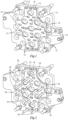
FIG. 1 shows a shuttle plate having a plurality of locking mechanisms with the shuttle plate in a position to receive an injection mold component; -
FIG. 2 shows the shuttle plate ofFIG. 1 with a plurality of injection mold components inserted into the installation areas of each locking mechanism; -
FIG. 3 shows the shuttle plate ofFIGs. 1 and 2 with the shuttle plate moved over to lock the injection mold components in the lock area of the locking mechanisms; -
FIG. 4 shows one of the locking mechanisms ofFIGs. 1, 2 , and3 with an injectionFIG. 4A shows another embodiment of the locking mechanism in which the lock area has a square edge; -
FIG. 4B shows another embodiment of the locking mechanism in which the lock area has a hex edge; -
FIG. 5 shows a closeup front view of an embodiment that comprises two overlapping shuttle plates with an injection mold component inserted into the installation area of two overlapping locking mechanisms; -
FIG. 5A is a cross sectional view of the two overlapping shuttle plates ofFIG. 5 ; -
FIG. 5B shows a closeup front view of the two overlapping shuttle plates ofFIG. 5 with the shuttle plates moved to secure the injection mold component in the lock area of the two overlapping locking mechanisms; -
FIG. 5C is a cross sectional view of the two overlapping shuttle plates ofFIG. 5B ; -
FIG. 6 is a perspective view of an embodiment in which the locking mechanism is a hinge in the open position; -
FIG. 6A is a perspective view of the locking mechanism ofFIG 6 in the locked position; -
FIG. 7 is a perspective view of an embodiment in which the locking mechanism comprises two hinges in opposition in the locked position; -
FIG. 8 shows an embodiment of the system for blind installation of injection mold components comprising a series of locking mechanisms that surround the notch of the injection mold component; -
FIG. 8A is a cross-sectional view of the locking mechanism ofFIG. 8 ; -
FIG. 9 is a perspective view of an embodiment in which the locking mechanism is a C-clamp in the open position; -
FIG. 9A is a perspective view of the locking mechanism ofFIG 9 in the locked position; -
FIG. 10 is a perspective view of an embodiment in which the locking mechanism comprises two C-clamps in opposition in the locked position; -
FIG. 11 shows an embodiment of the system in which the locking mechanism comprises a key slot that partially intersects the installation area showing a key inserted into the key slot to lock the injection mold component into the retainer plate; -
FIG. 12 shows an embodiment of the system in which the locking mechanism comprises two key slots that partially intersect the installation area showing two keys inserted into the key slots to lock the injection mold component into the retainer plate; -
FIG. 13 shows an embodiment of the system in which the locking mechanism comprises a key slot that fully intersects the installation area showing a key inserted into the key slot to lock the injection mold component into the retainer plate; -
FIG. 14 shows a top view of an embodiment in which the locking mechanism is an aperture in the open position; -
FIG. 14A is a top view of the locking mechanism ofFIG 14 in the locked position; and -
FIG. 14B is a perspective view of the locking mechanism ofFIG 14A . - Referring to the drawings, some of the reference numerals are used to designate the same or corresponding parts through several of the embodiments and figures shown and described. Corresponding parts are denoted in different embodiments with the addition of lowercase letters. Variations of corresponding parts in form or function that are depicted in the figures are described. It will be understood that variations in the embodiments can generally be interchanged without deviating from the invention.
- Injection molding machines typically comprise molds that have channels from a source of molten plastic that lead to a cavity that is shaped into the form of the final molded part. Molten plastic is injected through these channels into the cavity to create the final molded part. The mold is typically of two parts that are split along a line of the final molded part that would allow for the separation of the part from the mold. The plastic part may require various injection mold components such as pins, slides, sleeves, cores, etc. that may move to form details or assist with the removal or ejection of the final part from the mold. Additional injection mold components may need to be changed out to form different versions of the parts that could include varying orifices, diameters, lengths, widths, or other dimensions while utilizing much of the remainder of the mold.
- There are a variety of types of injection molding machines. These include single mold machines with one or more injection units (the injection unit heats the plastic and forces it into the mold) and two mold machines with two or more injection units. The single mold machines would typically include stack and cube molds with or without additional movement for subsequent plastic injection or assembly. Stack molds comprise two or more generally linear levels of mold cavities that are fed by a single injection unit for each type or color of plastic entering the mold. Cube molds comprise stationary and moving mold cavities in which a portion of the mold rotates to save cycle time, accept another plastic material, assembly, or ejection and are fed by one or more injection units.
- Two-mold machines have two or more injection units in opposition. The "B" side of each mold is attached to an ejector system. The center ejector system, or "tombstone", supports the clamp pressure of both molds and provides a method of ejecting parts from both molds. In a two-mold machine the molds could be the same or different. The stack height of each mold could be the same or different.
- In all the various types on injection molding machines, there is a premium on the space and weight of the various machine components. There is also a premium on the downtime experienced in switching out various injection mold components. The standard method of securing injection mold components is to install them in the mold (both prior to installing the mold or after the mold is installed on the machine) and then securing them into the machine with screws or bolts. Using the standard method requires significant clearance or space for manual installation, removal, and replacement of various injection mold components.
- What is presented is an improved system and method for installation, removal, and replacement of injection mold components to an injection molding machine. The system and method disclosed herein allows for the blind installation of injection mold components, which means that if the operator knows where on the mold the injection mold component needs to be installed, the operator does not have to remove the mold from the injection molding machine. This saves significant effort and time on the part of the operator and reduces overall downtime required to change out injection mold components.
-
Figs. 1-4 shows one embodiment of the system for blind installation ofinjection mold components 10 to an injection molding machine disclosed herein. In this embodiment, a retainer plate that is ashuttle plate 12 is mounted to the injection molding machine specifically at the location on the injection molding machine where theinjection mold components 10 are to be installed.FIG. 1 shows theshuttle plate 12 in the installation position. There is at least onelocking mechanism 14 on theshuttle plate 12. The location and number of lockingmechanisms 14 is determined by the application, but generally, the lockingmechanisms 14 are located to align with the various components of the injection molding machine where specificinjection mold components 10 are required to perform specific functions. - As best seen in
FIG. 4 , each lockingmechanism 14 has alarger installation area 16 and asmaller lock area 18. Eachinjection mold component 10 has anotch 20 that has a corresponding geometry to thesmaller lock area 18. Each saidinjection mold component 10 is configured to be inserted into theinstallation area 16 and theshuttle plate 12 is configured to move to seat thenotch 20 into thelock area 18 and secure theinjection mold component 10 to theshuttle plate 12. - Blind installation of
injection mold components 10 in an injection is easily achieved using the system disclosed herein. As shown inFIG. 1 , theshuttle plate 12 is moved to allow user access to theinstallation area 16 of thelocking mechanism 14. As shown inFIG. 2 , the user then inserts the required number and type ofinjection mold components 10 in theinstallation area 16 of acorresponding locking mechanism 14 in theshuttle plate 12. As shown inFIGs. 3 and4 , theshuttle plate 12 is moved so that thenotch 20 of eachinjection mold component 10 is seated into thelock area 18 in theircorresponding locking mechanism 14 in theshuttle plate 12. - This system can be used for any
injection mold component 10 that need to be added, removed, or replaced in an injection molding machine. This includes knockout rods, pins, slides, sleeves, cores, cavities, strippers, ejector pins, and other change components. - The configuration of the
locking mechanism 14 shown inFIGs. 1-4 shows that thelock area 18 as a semi-circular shape. This means that aninjection mold component 10 that hasnotch 20 that has a correspondinggeometry 10 to is free to rotate within theshuttle plate 12 unless it is otherwise anchored elsewhere in the injection molding machine. However, it is understood that other configurations oflock areas 18 are possible.FIG 4A shows an embodiment oflocking mechanism 14a haslock area 18a that is a square edge and thenotch 20a of theinjection mold component 10a has a corresponding square geometry to fit into thelock area 18a.FIG 4B shows an embodiment oflocking mechanism 14b haslock area 18b that is a hex edge and thenotch 20b of theinjection mold component 10b has a corresponding square geometry to fit into thelock area 18b. In either of the configurations shown inFIG. 4A and FIG 4B , the respectiveinjection mold components respective lock areas installation areas mechanism injection mold component - Another embodiment of the system for blind installation of
injection mold components 10c to an injection molding machine is shown inFIGs. 5-5C . This embodiment is similar to the embodiment disclosed inFIG. 1 -4 , however in this embodiment, twoshuttle plates 12c work in opposition to lock installedinjection mold components 10c in place. In this embodiment, twoshuttle plates 12c are aligned so that theirlocking mechanisms 14c overlap. In addition, eachlocking mechanism 14c is aligned in opposition to each other.FIGs. 5 and 5A show the twoshuttle plates 12c in the installation position with aninjection mold component 10c inserted into theinstallation area 16c of thelocking mechanism 14c of bothshuttle plates 12c. As shown inFIGs. 5B and 5C , locking theinjection mold components 10c in place is achieved by moving the twoshuttle plates 12c in the directions indicated by the arrows. Thenotch 20c of theinjection mold components 10c have a corresponding geometry to thelock areas 18c of bothshuttle plates 12c. Moving theshuttle plates 12c seat thenotch 20c of eachinjection mold component 10c thelock areas 18c of both lockingmechanism 14c and provide a more secure installation. -
FIGs. 6 and 6A shown another embodiment of the system for blind installation ofinjection mold components 10d. Similar to the earlier embodiments, in this embodiment, thelocking component 14d is a shutter that pivots to move theinstallation portion 16d and thelock portion 18d into place to secure theinjection molding component 10d. However, in this embodiment, the lockingcomponents 14d are mounted to a retainer plate (not shown) that allows the actuation of the lockingcomponents 14d. Eachinjection mold component 10d has anotch 20d that has a corresponding geometry to thelock portion 18d of the locking mechanism. Securing theinjection mold component 10d is achieved by the user inserting theinjection mold component 10d at the required location and actuating thelocking mechanism 14d to pivot thelock portion 18d into thenotch 20d. The lockingcomponents 14d may be actuated mechanically, hydraulically, or pneumatically. -
FIG. 7 shows another embodiment of the system for blind installation ofinjection mold components 10e comprising two lockingcomponents 14e similar to those shown inFIGs. 6 and 6A that to secure theinjection mold component 10e. Similar to the earlier embodiments, in this embodiment, the lockingcomponents 14e comprisesinstallation portions 16e and alock portions 18e. In this embodiment, the lockingcomponents 14e are also mounted to a retainer plate (not shown) that allows the actuation of the lockingcomponents 14e. Eachinjection mold component 10e has a notch 20e that has a corresponding geometry to thelock portion 18e of thelocking mechanism 14e. Securing theinjection mold component 10e is achieved by the user inserting theinjection mold component 10e at the required location and actuating the lockingmechanisms 14e to pivot bothlock portions 18e into the notch 20e. The lockingcomponents 14e may be actuated mechanically, hydraulically, or pneumatically. -
FIGs. 8 and 8A show another embodiment of the system for blind installation ofinjection mold components 10f comprising a series of lockingmechanisms 14f that surround thenotch 20f of theinjection mold component 10f. In the embodiment shown, fourlocking mechanisms 14f are located within aretainer plate 12f. Securing theinjection mold component 10f is achieved by the user inserting theinjection mold component 10f at the required location and actuating the lockingmechanisms 14f to move thelock portions 18f into thenotch 20f. The lockingcomponents 14f may be actuated mechanically, hydraulically, or pneumatically. -
FIGs. 9 and 9A show another embodiment of the system for blind installation ofinjection mold components 10g. Similar to the earlier embodiments, in this embodiment, thelocking component 14g is a C-clamp that slides to move theinstallation portion 16g and alock portion 18g to secure theinjection mold components 10g. As with some of the earlier embodiments, in this embodiment, the lockingcomponents 14g are mounted to a retainer plate (not shown) that allows the actuation of the lockingcomponents 14g. Eachinjection mold component 10g has anotch 20g that has a corresponding geometry to thelock portion 18g of the locking mechanism. Securing theinjection mold component 10g is achieved by the user inserting theinjection mold component 10g at the required location and actuating thelocking mechanism 14g to slide thelock portion 18g into thenotch 20g. The lockingcomponents 14g may be actuated mechanically, hydraulically, or pneumatically. -
FIG. 10 shows another embodiment of the system for blind installation ofinjection mold components 10h comprising two lockingcomponents 14h similar to those shown inFIGs. 9 and 9A that to secure theinjection mold component 10h. Similar to the earlier embodiments, in this embodiment, the lockingcomponents 14h comprisesinstallation portions 16h and alock portions 18h. In this embodiment, the lockingcomponents 14h are also mounted to a retainer plate (not shown) that allows the actuation of the lockingcomponents 14h. Eachinjection mold component 10h has anotch 20h that has a corresponding geometry to thelock portion 18h of the locking mechanism. Securing theinjection mold component 10h is achieved by the user inserting theinjection mold component 10h at the required location and actuating the lockingmechanisms 14h to move bothlock portions 18h into thenotch 20h. The lockingcomponents 14h may be actuated mechanically, hydraulically, or pneumatically. -
FIG. 11 shows another embodiment of the system for blind installation of injection mold components 10i. In this embodiment theretainer plate 12i has at least one locking mechanism 14i. The locking mechanism 14i comprises an installation area 16i and a lock area 18i. The installation area 16i is configured to receive an injection mold component 10i. The lock area 18i comprises at least one key slot 24i that runs the length of theretainer plate 12i and at least partially intersects the installation area 16i of the locking mechanism. A key 26i is insertable into the key slot 24i. Each injection mold component 10i has a notch 20i that has a geometry configured such that the insertion of the key 26i into the key slot 24i intersects the installation area 16i and the notch 20i to lock the injection mold component 10i into theretainer plate 12i. -
FIG. 12 shows another embodiment of the system for blind installation ofinjection mold components 10j that is a variation of the embodiment shown inFIG. 11 . In this embodiment, theinstallation area 16j is partially intersected by twokey slots 24j and up to twokeys 26j may be used to secure theinjection mold component 10j into theretainer plate 12j. -
FIG. 13 shows another embodiment of the system for blind installation ofinjection mold components 10k that is another variation of the embodiment shown inFIG. 11 . In this embodiment, theinstallation area 16k is fully intersected by akey slot 24k. Thenotch 20k is a hole that aligns with thekey slot 24k. Theinjection mold component 10k is secured to theretainer plate 12k by inserting a key 26k inserted into thekey slot 24k and through thenotch 20k. -
FIGs. 14, 14A, and 14B shown another embodiment of the system for blind installation of injection mold components 10l. In this embodiment, the locking component 14l is an aperture that telescopes to move the lock portion 18l into place to secure the injection molding component 10l. In this embodiment, the locking components 14l are mounted to a retainer plate (not shown) that allows the actuation of the locking components 14l. Each injection mold component 10l has a notch 20l that has a corresponding geometry to the lock portion 18l of the locking mechanism 14l. Securing the injection mold component 10l is achieved by the user inserting the injection mold component 10l at the required location and actuating the locking mechanism 14l to telescope the lock portion 18l into the notch 20l. - The invention is set out in the appended set of claims.
Claims (8)
- A system for blind installation of injection mold components, the system comprising:an injection mold component (10i);a retainer plate (12i) comprising at least one locking mechanism (14i), whereinsaid locking mechanism (14i) has an installation area (16i) and a lock area (18i), andsaid lock area (18i) comprises at least one key slot (24i) that at least partially intersects said installation area (16i); anda key (26i) insertable into each said key slot (24i), whereinsaid installation area (16i) of said retainer plate (12i) is configured to receive said injection mold component (10i) without removing the mold from the injection molding machine,said injection mold component (12i) has a notch (20i) that has a geometry configured such that insertion of said key (26i) into said at least one key slot (24i) intersects said installation area (16i) of said retainer plate (12i) and said notch (20i) of said injection mold component (10i) to lock said injection mold component (10i) into said retainer plate (12i), characterised in thatsaid at least one key slot (24i) extends along the complete length of said retainer plate (12i).
- The system of claim 1, wherein said installation area (16i) is partially intersected by two said key slots (26i).
- The system of claim 1, whereinsaid installation area (16i) is fully intersected by a said at least one key slot (24i), andsaid notch (20i) includes a hole defined through the injection mold component (10i).
- The system of any one of claims 1-3, wherein said lock area (18i) of said retainer plate (12i) has a semi-circular shape, and said injection mold component (10i) is freely rotatable in said retainer plate (12i) in the absence of anchoring away from said retainer plate (12i).
- The system of any one of claims 1-3, wherein said injection mold component (10i) is not rotatable within said lock area (18i) of said retainer plate (12i).
- The system of claim 5, wherein said lock area (18i) of the retainer plate (12i) has a square geometry and said notch (20i) defined by said injection mold component (10i) has a corresponding square geometry.
- The system of claim 5, wherein said lock area (18i) of the retainer plate (12i) has a hex edge and said notch (20i) defined by said injection mold component (10i) has a corresponding geometry.
- The system of any one of claims 1-7, wherein said injection mold component (10i) is one of a knockout rod, a slide, a sleeve, a stripper, a core, a cavity, an ejector pin, or a change component.
Priority Applications (1)
| Application Number | Priority Date | Filing Date | Title |
|---|---|---|---|
| EP24211552.5A EP4484115A3 (en) | 2017-09-29 | 2018-09-25 | Blind installation of injection mold components |
Applications Claiming Priority (4)
| Application Number | Priority Date | Filing Date | Title |
|---|---|---|---|
| US201762565998P | 2017-09-29 | 2017-09-29 | |
| US201862647100P | 2018-03-23 | 2018-03-23 | |
| US201862672381P | 2018-05-16 | 2018-05-16 | |
| PCT/US2018/052623 WO2019067437A1 (en) | 2017-09-29 | 2018-09-25 | Blind installation of injection mold components |
Related Child Applications (1)
| Application Number | Title | Priority Date | Filing Date |
|---|---|---|---|
| EP24211552.5A Division EP4484115A3 (en) | 2017-09-29 | 2018-09-25 | Blind installation of injection mold components |
Publications (3)
| Publication Number | Publication Date |
|---|---|
| EP3687759A1 EP3687759A1 (en) | 2020-08-05 |
| EP3687759A4 EP3687759A4 (en) | 2021-06-16 |
| EP3687759B1 true EP3687759B1 (en) | 2024-11-20 |
Family
ID=65902013
Family Applications (2)
| Application Number | Title | Priority Date | Filing Date |
|---|---|---|---|
| EP18861340.0A Active EP3687759B1 (en) | 2017-09-29 | 2018-09-25 | Blind installation of injection mold components |
| EP24211552.5A Pending EP4484115A3 (en) | 2017-09-29 | 2018-09-25 | Blind installation of injection mold components |
Family Applications After (1)
| Application Number | Title | Priority Date | Filing Date |
|---|---|---|---|
| EP24211552.5A Pending EP4484115A3 (en) | 2017-09-29 | 2018-09-25 | Blind installation of injection mold components |
Country Status (5)
| Country | Link |
|---|---|
| US (1) | US10919201B2 (en) |
| EP (2) | EP3687759B1 (en) |
| CA (1) | CA3074909C (en) |
| ES (1) | ES2998434T3 (en) |
| WO (1) | WO2019067437A1 (en) |
Families Citing this family (4)
| Publication number | Priority date | Publication date | Assignee | Title |
|---|---|---|---|---|
| US12472668B2 (en) * | 2022-07-29 | 2025-11-18 | Milacron Marketing Company Llc | Flex plate for guiding device of injection molding machine |
| CN116141596A (en) * | 2023-03-09 | 2023-05-23 | 费梦迪 | A kind of injection mold and injection molding process thereof |
| CN116619689B (en) * | 2023-06-01 | 2025-09-12 | 永岳医疗科技(昆山)有限公司 | A scraper mold with interchangeable mold core |
| CN120438573B (en) * | 2025-07-14 | 2025-10-31 | 江苏菲瑞达模具科技有限公司 | An easy-to-disassemble die-casting mold for titanium castings |
Family Cites Families (16)
| Publication number | Priority date | Publication date | Assignee | Title |
|---|---|---|---|---|
| DE2742166C2 (en) * | 1977-09-20 | 1980-06-26 | Hasco-Normalien Hasenclever & Co, 5880 Luedenscheid | Device for locking and unlocking mold plates of an injection molding or compression mold |
| US4150931A (en) * | 1977-10-03 | 1979-04-24 | The Pentaject Corporation | Injection molding apparatus with quick change molds |
| US4472128A (en) * | 1983-06-02 | 1984-09-18 | Sharp Die And Mold Co. | Quick change locator clamp assembly for plastic molding machine |
| US4684101A (en) | 1985-05-28 | 1987-08-04 | General Motors Corporation | Quick change mold insert |
| JPS63227315A (en) * | 1986-10-15 | 1988-09-21 | Gifu Hasukii Kk | Retainer for stamper in mold for injection molding |
| US4765585A (en) | 1987-02-27 | 1988-08-23 | Superior Die Set Corporation | Slide retainer for injection molds |
| DE9107470U1 (en) * | 1991-06-18 | 1991-08-22 | HA-WI Kunststoffe GmbH, 5928 Bad Laasphe | Quick release device |
| US5219595A (en) * | 1991-08-13 | 1993-06-15 | Sermatech International, Inc. | Apparatus for separating mold plates from a casting |
| JPH11935A (en) * | 1997-06-11 | 1999-01-06 | Fuji Photo Film Co Ltd | Injection molding die |
| US6431852B1 (en) * | 2001-02-02 | 2002-08-13 | Leo A. Vandenberg | Internal latch for an injection mold |
| EP2418068B1 (en) | 2010-08-10 | 2016-11-09 | Mold-Masters (2007) Limited | Quick-change molding system for injection molding |
| ITRM20110126A1 (en) * | 2011-03-16 | 2012-09-17 | Sipa Progettazione Automaz | BLOWING MOLD |
| US20150028504A1 (en) * | 2012-04-20 | 2015-01-29 | David Frost | Quick change mold system |
| DE102013008302A1 (en) * | 2013-05-15 | 2014-11-20 | Braunform Gmbh | Tool for injection molding plastic parts |
| DE102016121995A1 (en) | 2016-11-16 | 2018-05-17 | Braunform GmbH Kunststoff- und Pharmatechnik | Tool element and tool |
| DE102016121996A1 (en) | 2016-11-16 | 2018-05-17 | Braunform GmbH Kunststoff- und Pharmatechnik | Tool element and tool and method for removing a mold insert from a tool element |
-
2018
- 2018-09-25 US US16/088,794 patent/US10919201B2/en active Active
- 2018-09-25 CA CA3074909A patent/CA3074909C/en active Active
- 2018-09-25 WO PCT/US2018/052623 patent/WO2019067437A1/en not_active Ceased
- 2018-09-25 EP EP18861340.0A patent/EP3687759B1/en active Active
- 2018-09-25 EP EP24211552.5A patent/EP4484115A3/en active Pending
- 2018-09-25 ES ES18861340T patent/ES2998434T3/en active Active
Also Published As
| Publication number | Publication date |
|---|---|
| US20200061891A1 (en) | 2020-02-27 |
| WO2019067437A1 (en) | 2019-04-04 |
| EP4484115A3 (en) | 2025-03-12 |
| CA3074909C (en) | 2022-08-02 |
| CA3074909A1 (en) | 2019-04-04 |
| US10919201B2 (en) | 2021-02-16 |
| ES2998434T3 (en) | 2025-02-20 |
| EP3687759A1 (en) | 2020-08-05 |
| EP3687759A4 (en) | 2021-06-16 |
| EP4484115A2 (en) | 2025-01-01 |
Similar Documents
| Publication | Publication Date | Title |
|---|---|---|
| CA3074909C (en) | Blind installation of injection mold components | |
| EP2442956B1 (en) | Injection molding tool with core assembly | |
| JPH0459321A (en) | Injection mold device | |
| EP1155802A2 (en) | Holding device for a mould, mould half or a mould carrier in an injection moulding machine | |
| EP3366447B1 (en) | Undercut processing mechanism, molding die, and molded product | |
| US6609903B2 (en) | Apparatus for molding a connector | |
| EP0519438A2 (en) | Quick fastening apparatus | |
| EP2164676A2 (en) | Tool for pin tumbler locks | |
| EP0184744B1 (en) | Tool, in particular an injection-moulding die | |
| JP4774341B2 (en) | Molding equipment | |
| EP3117977B1 (en) | Tool half for a mould of an injection moulding machine with a hot runner system | |
| WO2021180871A1 (en) | Battery-holder assembly for an electric bike | |
| EP3401076B1 (en) | Ejection unit for moulds | |
| JP2025130290A (en) | Assembly | |
| DE102019111880A1 (en) | Electrical connector system | |
| DE102007053123C5 (en) | Tool for injection molding plastic parts | |
| US12600070B2 (en) | Mold tool for injection molding | |
| CN101132897A (en) | Device for receiving a casting mould | |
| KR100874977B1 (en) | Mold Assembly | |
| SE434479B (en) | SETS AND FORMS FOR CASTING OF CONCRETE ELEMENTS | |
| US5017123A (en) | Knockout bar mounting for injection molding machines | |
| DE102013218282A1 (en) | Multi-part blow mold, in particular for the production of plastic bottles | |
| EP2489491B1 (en) | Method and device for producing ball bearing rings | |
| EP4215319A1 (en) | Automatically and manually operated jaw change system | |
| DE102018211737B4 (en) | Machine system, molding machine, tool block and method for equipping a molding machine |
Legal Events
| Date | Code | Title | Description |
|---|---|---|---|
| STAA | Information on the status of an ep patent application or granted ep patent |
Free format text: STATUS: THE INTERNATIONAL PUBLICATION HAS BEEN MADE |
|
| PUAI | Public reference made under article 153(3) epc to a published international application that has entered the european phase |
Free format text: ORIGINAL CODE: 0009012 |
|
| STAA | Information on the status of an ep patent application or granted ep patent |
Free format text: STATUS: REQUEST FOR EXAMINATION WAS MADE |
|
| 17P | Request for examination filed |
Effective date: 20200306 |
|
| AK | Designated contracting states |
Kind code of ref document: A1 Designated state(s): AL AT BE BG CH CY CZ DE DK EE ES FI FR GB GR HR HU IE IS IT LI LT LU LV MC MK MT NL NO PL PT RO RS SE SI SK SM TR |
|
| AX | Request for extension of the european patent |
Extension state: BA ME |
|
| DAV | Request for validation of the european patent (deleted) | ||
| DAX | Request for extension of the european patent (deleted) | ||
| TPAC | Observations filed by third parties |
Free format text: ORIGINAL CODE: EPIDOSNTIPA |
|
| A4 | Supplementary search report drawn up and despatched |
Effective date: 20210519 |
|
| RIC1 | Information provided on ipc code assigned before grant |
Ipc: B29C 45/17 20060101AFI20210512BHEP Ipc: B29C 45/26 20060101ALI20210512BHEP |
|
| STAA | Information on the status of an ep patent application or granted ep patent |
Free format text: STATUS: EXAMINATION IS IN PROGRESS |
|
| 17Q | First examination report despatched |
Effective date: 20220301 |
|
| GRAP | Despatch of communication of intention to grant a patent |
Free format text: ORIGINAL CODE: EPIDOSNIGR1 |
|
| STAA | Information on the status of an ep patent application or granted ep patent |
Free format text: STATUS: GRANT OF PATENT IS INTENDED |
|
| INTG | Intention to grant announced |
Effective date: 20240613 |
|
| GRAS | Grant fee paid |
Free format text: ORIGINAL CODE: EPIDOSNIGR3 |
|
| GRAA | (expected) grant |
Free format text: ORIGINAL CODE: 0009210 |
|
| STAA | Information on the status of an ep patent application or granted ep patent |
Free format text: STATUS: THE PATENT HAS BEEN GRANTED |
|
| P01 | Opt-out of the competence of the unified patent court (upc) registered |
Free format text: CASE NUMBER: APP_53236/2024 Effective date: 20240924 |
|
| AK | Designated contracting states |
Kind code of ref document: B1 Designated state(s): AL AT BE BG CH CY CZ DE DK EE ES FI FR GB GR HR HU IE IS IT LI LT LU LV MC MK MT NL NO PL PT RO RS SE SI SK SM TR |
|
| REG | Reference to a national code |
Ref country code: GB Ref legal event code: FG4D |
|
| REG | Reference to a national code |
Ref country code: CH Ref legal event code: EP |
|
| REG | Reference to a national code |
Ref country code: DE Ref legal event code: R096 Ref document number: 602018076823 Country of ref document: DE |
|
| REG | Reference to a national code |
Ref country code: IE Ref legal event code: FG4D |
|
| REG | Reference to a national code |
Ref country code: ES Ref legal event code: FG2A Ref document number: 2998434 Country of ref document: ES Kind code of ref document: T3 Effective date: 20250220 |
|
| REG | Reference to a national code |
Ref country code: LT Ref legal event code: MG9D |
|
| REG | Reference to a national code |
Ref country code: NL Ref legal event code: MP Effective date: 20241120 |
|
| PG25 | Lapsed in a contracting state [announced via postgrant information from national office to epo] |
Ref country code: HR Free format text: LAPSE BECAUSE OF FAILURE TO SUBMIT A TRANSLATION OF THE DESCRIPTION OR TO PAY THE FEE WITHIN THE PRESCRIBED TIME-LIMIT Effective date: 20241120 Ref country code: IS Free format text: LAPSE BECAUSE OF FAILURE TO SUBMIT A TRANSLATION OF THE DESCRIPTION OR TO PAY THE FEE WITHIN THE PRESCRIBED TIME-LIMIT Effective date: 20250320 Ref country code: PT Free format text: LAPSE BECAUSE OF FAILURE TO SUBMIT A TRANSLATION OF THE DESCRIPTION OR TO PAY THE FEE WITHIN THE PRESCRIBED TIME-LIMIT Effective date: 20250320 |
|
| PG25 | Lapsed in a contracting state [announced via postgrant information from national office to epo] |
Ref country code: FI Free format text: LAPSE BECAUSE OF FAILURE TO SUBMIT A TRANSLATION OF THE DESCRIPTION OR TO PAY THE FEE WITHIN THE PRESCRIBED TIME-LIMIT Effective date: 20241120 Ref country code: NL Free format text: LAPSE BECAUSE OF FAILURE TO SUBMIT A TRANSLATION OF THE DESCRIPTION OR TO PAY THE FEE WITHIN THE PRESCRIBED TIME-LIMIT Effective date: 20241120 |
|
| PG25 | Lapsed in a contracting state [announced via postgrant information from national office to epo] |
Ref country code: BG Free format text: LAPSE BECAUSE OF FAILURE TO SUBMIT A TRANSLATION OF THE DESCRIPTION OR TO PAY THE FEE WITHIN THE PRESCRIBED TIME-LIMIT Effective date: 20241120 |
|
| PG25 | Lapsed in a contracting state [announced via postgrant information from national office to epo] |
Ref country code: NO Free format text: LAPSE BECAUSE OF FAILURE TO SUBMIT A TRANSLATION OF THE DESCRIPTION OR TO PAY THE FEE WITHIN THE PRESCRIBED TIME-LIMIT Effective date: 20250220 |
|
| PG25 | Lapsed in a contracting state [announced via postgrant information from national office to epo] |
Ref country code: LV Free format text: LAPSE BECAUSE OF FAILURE TO SUBMIT A TRANSLATION OF THE DESCRIPTION OR TO PAY THE FEE WITHIN THE PRESCRIBED TIME-LIMIT Effective date: 20241120 Ref country code: GR Free format text: LAPSE BECAUSE OF FAILURE TO SUBMIT A TRANSLATION OF THE DESCRIPTION OR TO PAY THE FEE WITHIN THE PRESCRIBED TIME-LIMIT Effective date: 20250221 |
|
| PG25 | Lapsed in a contracting state [announced via postgrant information from national office to epo] |
Ref country code: PL Free format text: LAPSE BECAUSE OF FAILURE TO SUBMIT A TRANSLATION OF THE DESCRIPTION OR TO PAY THE FEE WITHIN THE PRESCRIBED TIME-LIMIT Effective date: 20241120 |
|
| PG25 | Lapsed in a contracting state [announced via postgrant information from national office to epo] |
Ref country code: RS Free format text: LAPSE BECAUSE OF FAILURE TO SUBMIT A TRANSLATION OF THE DESCRIPTION OR TO PAY THE FEE WITHIN THE PRESCRIBED TIME-LIMIT Effective date: 20250220 |
|
| PG25 | Lapsed in a contracting state [announced via postgrant information from national office to epo] |
Ref country code: SM Free format text: LAPSE BECAUSE OF FAILURE TO SUBMIT A TRANSLATION OF THE DESCRIPTION OR TO PAY THE FEE WITHIN THE PRESCRIBED TIME-LIMIT Effective date: 20241120 |
|
| PG25 | Lapsed in a contracting state [announced via postgrant information from national office to epo] |
Ref country code: DK Free format text: LAPSE BECAUSE OF FAILURE TO SUBMIT A TRANSLATION OF THE DESCRIPTION OR TO PAY THE FEE WITHIN THE PRESCRIBED TIME-LIMIT Effective date: 20241120 |
|
| PG25 | Lapsed in a contracting state [announced via postgrant information from national office to epo] |
Ref country code: EE Free format text: LAPSE BECAUSE OF FAILURE TO SUBMIT A TRANSLATION OF THE DESCRIPTION OR TO PAY THE FEE WITHIN THE PRESCRIBED TIME-LIMIT Effective date: 20241120 |
|
| PG25 | Lapsed in a contracting state [announced via postgrant information from national office to epo] |
Ref country code: RO Free format text: LAPSE BECAUSE OF FAILURE TO SUBMIT A TRANSLATION OF THE DESCRIPTION OR TO PAY THE FEE WITHIN THE PRESCRIBED TIME-LIMIT Effective date: 20241120 |
|
| PG25 | Lapsed in a contracting state [announced via postgrant information from national office to epo] |
Ref country code: SK Free format text: LAPSE BECAUSE OF FAILURE TO SUBMIT A TRANSLATION OF THE DESCRIPTION OR TO PAY THE FEE WITHIN THE PRESCRIBED TIME-LIMIT Effective date: 20241120 |
|
| PG25 | Lapsed in a contracting state [announced via postgrant information from national office to epo] |
Ref country code: CZ Free format text: LAPSE BECAUSE OF FAILURE TO SUBMIT A TRANSLATION OF THE DESCRIPTION OR TO PAY THE FEE WITHIN THE PRESCRIBED TIME-LIMIT Effective date: 20241120 |
|
| REG | Reference to a national code |
Ref country code: DE Ref legal event code: R097 Ref document number: 602018076823 Country of ref document: DE |
|
| PG25 | Lapsed in a contracting state [announced via postgrant information from national office to epo] |
Ref country code: SE Free format text: LAPSE BECAUSE OF FAILURE TO SUBMIT A TRANSLATION OF THE DESCRIPTION OR TO PAY THE FEE WITHIN THE PRESCRIBED TIME-LIMIT Effective date: 20241120 |
|
| PLBE | No opposition filed within time limit |
Free format text: ORIGINAL CODE: 0009261 |
|
| STAA | Information on the status of an ep patent application or granted ep patent |
Free format text: STATUS: NO OPPOSITION FILED WITHIN TIME LIMIT |
|
| REG | Reference to a national code |
Ref country code: CH Ref legal event code: U11 Free format text: ST27 STATUS EVENT CODE: U-0-0-U10-U11 (AS PROVIDED BY THE NATIONAL OFFICE) Effective date: 20251001 |
|
| PGFP | Annual fee paid to national office [announced via postgrant information from national office to epo] |
Ref country code: DE Payment date: 20250926 Year of fee payment: 8 |
|
| PGFP | Annual fee paid to national office [announced via postgrant information from national office to epo] |
Ref country code: IT Payment date: 20250922 Year of fee payment: 8 |
|
| PGFP | Annual fee paid to national office [announced via postgrant information from national office to epo] |
Ref country code: GB Payment date: 20250923 Year of fee payment: 8 |
|
| PGFP | Annual fee paid to national office [announced via postgrant information from national office to epo] |
Ref country code: FR Payment date: 20250925 Year of fee payment: 8 Ref country code: AT Payment date: 20250917 Year of fee payment: 8 |
|
| 26N | No opposition filed |
Effective date: 20250821 |
|
| PGFP | Annual fee paid to national office [announced via postgrant information from national office to epo] |
Ref country code: CH Payment date: 20251001 Year of fee payment: 8 |
|
| PGFP | Annual fee paid to national office [announced via postgrant information from national office to epo] |
Ref country code: ES Payment date: 20251015 Year of fee payment: 8 |
|
| REG | Reference to a national code |
Ref country code: AT Ref legal event code: UEP Ref document number: 1743190 Country of ref document: AT Kind code of ref document: T Effective date: 20241120 |