EP0184744B1 - Tool, in particular an injection-moulding die - Google Patents
Tool, in particular an injection-moulding die Download PDFInfo
- Publication number
- EP0184744B1 EP0184744B1 EP85115239A EP85115239A EP0184744B1 EP 0184744 B1 EP0184744 B1 EP 0184744B1 EP 85115239 A EP85115239 A EP 85115239A EP 85115239 A EP85115239 A EP 85115239A EP 0184744 B1 EP0184744 B1 EP 0184744B1
- Authority
- EP
- European Patent Office
- Prior art keywords
- clamping
- quick
- plates
- tool
- bolts
- Prior art date
- Legal status (The legal status is an assumption and is not a legal conclusion. Google has not performed a legal analysis and makes no representation as to the accuracy of the status listed.)
- Expired - Lifetime
Links
Images
Classifications
-
- B—PERFORMING OPERATIONS; TRANSPORTING
- B29—WORKING OF PLASTICS; WORKING OF SUBSTANCES IN A PLASTIC STATE IN GENERAL
- B29C—SHAPING OR JOINING OF PLASTICS; SHAPING OF MATERIAL IN A PLASTIC STATE, NOT OTHERWISE PROVIDED FOR; AFTER-TREATMENT OF THE SHAPED PRODUCTS, e.g. REPAIRING
- B29C45/00—Injection moulding, i.e. forcing the required volume of moulding material through a nozzle into a closed mould; Apparatus therefor
- B29C45/17—Component parts, details or accessories; Auxiliary operations
- B29C45/1742—Mounting of moulds; Mould supports
- B29C45/1743—Mounting of moulds; Mould supports using mounting means projecting from the back side of the mould or from the front side of the mould support
-
- B—PERFORMING OPERATIONS; TRANSPORTING
- B23—MACHINE TOOLS; METAL-WORKING NOT OTHERWISE PROVIDED FOR
- B23Q—DETAILS, COMPONENTS, OR ACCESSORIES FOR MACHINE TOOLS, e.g. ARRANGEMENTS FOR COPYING OR CONTROLLING; MACHINE TOOLS IN GENERAL CHARACTERISED BY THE CONSTRUCTION OF PARTICULAR DETAILS OR COMPONENTS; COMBINATIONS OR ASSOCIATIONS OF METAL-WORKING MACHINES, NOT DIRECTED TO A PARTICULAR RESULT
- B23Q1/00—Members which are comprised in the general build-up of a form of machine, particularly relatively large fixed members
- B23Q1/0063—Connecting non-slidable parts of machine tools to each other
-
- B—PERFORMING OPERATIONS; TRANSPORTING
- B29—WORKING OF PLASTICS; WORKING OF SUBSTANCES IN A PLASTIC STATE IN GENERAL
- B29C—SHAPING OR JOINING OF PLASTICS; SHAPING OF MATERIAL IN A PLASTIC STATE, NOT OTHERWISE PROVIDED FOR; AFTER-TREATMENT OF THE SHAPED PRODUCTS, e.g. REPAIRING
- B29C33/00—Moulds or cores; Details thereof or accessories therefor
- B29C33/30—Mounting, exchanging or centering
- B29C33/305—Mounting of moulds or mould support plates
-
- Y—GENERAL TAGGING OF NEW TECHNOLOGICAL DEVELOPMENTS; GENERAL TAGGING OF CROSS-SECTIONAL TECHNOLOGIES SPANNING OVER SEVERAL SECTIONS OF THE IPC; TECHNICAL SUBJECTS COVERED BY FORMER USPC CROSS-REFERENCE ART COLLECTIONS [XRACs] AND DIGESTS
- Y10—TECHNICAL SUBJECTS COVERED BY FORMER USPC
- Y10S—TECHNICAL SUBJECTS COVERED BY FORMER USPC CROSS-REFERENCE ART COLLECTIONS [XRACs] AND DIGESTS
- Y10S100/00—Presses
- Y10S100/918—Bolster and die
Definitions
- the invention relates to a quick-action clamping device for releasably clamping the halves of a tool that can be moved relative to one another, which can in particular be an injection mold, on the mounting plates of a machine.
- tool or mold halves are to be understood as meaning the two parts of a tool or a mold which can be moved relative to one another, even if the parting plane does not extend in the middle of the tool or the mold, and consequently the parts of the tool or mold which can be moved relative to one another are designed quite differently could be.
- PCT application WO 83/01038 describes a device for clamping molds on mold carriers of an injection molding machine, in which the mold extend the halves of a tool to the side of clamping bolts which engage in corresponding recesses in the mold carrier plates.
- guides run in the mold carrier plates in which wedges are movably guided as locking means for the clamping bolts, which in the locking case extend through transverse recesses in the clamping bolts and thereby secure them in their positions .
- the actuation of the locking means designed as wedges between their locking positions engaging in the transverse recesses of the tensioning bolts and their positions retracted relative to the tensioning bolts serve to act upon by hydraulic cylinders.
- the quick coupling means each comprise a plurality of locking bolts projecting laterally beyond the relevant tool half, received in corresponding receiving bores of the quick release plate assigned to the respective tool half, and in the latter approximately perpendicular to their longitudinal axes penetrating transverse recesses which engage positively locking bars are in turn rotatably received in bearing bores running at right angles to the receiving bores for the clamping bolts and are axially displaceable from their engagement positions with the transverse recesses of the clamping bolts and are equipped with clamping eccentrics that can be clamped in the coupling position with a clamping surface of the respective penetrated transverse recess of a clamping bolt.
- the invention is intended to provide an improved quick-action clamping device of the type and intended use explained at the outset, which is equipped with simple and functionally reliable means for quick and unproblematic assembly and disassembly of a tool.
- Such a design of the quick release device with conical clamping pins and the latter adapted mounting holes in the form of inner cones enables easy insertion of the clamping pins into the mounting holes with simultaneous centering, but also unproblematic decoupling for the purpose of separating a tool half from the quick release plate assigned in the coupling position.
- easy handling is ensured if the cones tapering toward the free end of each clamping bolt extend over the entire length of the sections of the clamping bolts which engage in the receiving bores of the quick-action clamping plates in the coupling position.
- the quick-action clamping device which comprises at least two clamping bolts per tool half, thus ensures, in addition to its coupling function, also a correct assignment of a tool half and a quick-action clamping plate to one another, so that no other centering means or special alignment of the tools is required during installation.
- the locking rods can be brought into positive engagement positions with the transverse recesses of the clamping bolts by axially displacing them in their bearing bores, so that the respective tool can already be locked and held in this position half is reached on the assigned quick release plate or vice versa.
- a fastening device is known from US Pat. No. 2,781,199, in which a conical clamping pin engages in a correspondingly designed receiving hole and can be clamped in the coupling position by means of a clamping eccentric, but this is not a connection of a tool or a tool half with a machine-side mounting plate, but about the interchangeable arrangement of a tool holder, for example a chuck, on a clamping plate of a lathe.
- the clamping eccentric is rotatable, but is not mounted so that it can be pulled out axially from its engagement position with a clamping pin transverse recess, but rather is provided with a flattened area on one side which, in a certain rotational position, allows the clamping pins to be inserted freely into their receiving bores and to be uncoupled uncoupled.
- the transverse recesses serving to lock the clamping eccentrics with the clamping bolts are designed as C-shaped troughs of shallow depth.
- the fastening device according to US-A-2 781 199 is therefore in the coupling position Rigid system that could not meet the intended purpose of the quick release device according to the invention, because in view of the intermittent loads when closing and opening the halves of a clamped tool when the device according to the invention is used as intended, the coupling connection between the tool halves and the quick release plates could be loosened gradually .
- the U-shaped transverse recesses of the clamping bolts extend approximately to the longitudinal axis of the clamping bolt. This ensures that not only a positive locking of the clamping bolts takes place in the coupling position, but the clamping eccentrics of the locking rods engage the pronounced clamping surfaces of the U-shaped transverse recesses and cause a limited elastic deformation of the clamping bolt ends when clamping, which when the clamping eccentrics are removed spring back the mediated clamping forces. This is one of the reasons why, without prejudice to precise clamping in the device according to the invention, the clamping bolts do not become jammed in the conical bores which accommodate them.
- the elastic deformability of the clamping bolts as a result of the attack of the clamping eccentrics on the clamping surfaces of the U-shaped transverse recesses is also of importance in the invention in that when the eccentric clamping is removed, the resetting of the clamping bolt ends elastically deformed in the clamping position is ensured in the original position, which is desirable installation repeatability is guaranteed.
- gradual loosening cannot occur during operation.
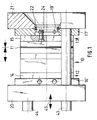
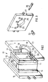
- the injection mold 10 shown in FIG. 2 on its own has two mold halves 12, 13 separated in a parting line 11, with outer plates 14, 15, which are accommodated between quick-action clamping plates 16, 17 and are firmly but releasably connected to them by quick-coupling means to be explained below are.
- the quick release plates 16, 17 are provided in the region of a recess 18 which is initially of no further interest on the sides facing away from one another with centering collars 19 which rise above their outer surfaces.
- the quick-action clamping plates 16 ', 17' are not provided with centering collars, but with a recess adapted to the centering recess 22 in the mounting plates 20, 21 of the machine, into which a centering ring 19 'is inserted.
- the screw connections for fastening the quick release plates 16 ', 17' to the mounting plates 20, 21 'of the machine are also not shown.
- the quick coupling means for the fixed, but at any time releasable connection of the mold halves 12, 13 with a quick release plate 16, 17 or 16 ', 17' consist of the outer plates 14, 15 of the mold halves 12, 13 firmly connected and on the outside via the above-mentioned planes stretching clamping bolts 24, from receiving bores 25 arranged in accordance with the position of these clamping bolts in the quick-action clamping plates which extend at right angles to the plane of the quick-action clamping plates and are arranged symmetrically with respect to a vertical plane on both sides of the central recesses 18 penetrating the quick-action clamping plates, and from locking rods 26 which are received in bearing bores 27 in the manner shown in FIGS. 2 and 3 which extend in the quick release plates perpendicular to the mounting holes 25 for the clamping bolts 24 and cut these mounting holes off-center. This will be explained in more detail below.
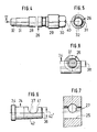
- the locking rods 26 have a pin section 28 which is adapted to the bearing bore 27 and is delimited on one side by an annular collar 29 to which a key attachment surface 30 adjoins.
- the pin section 28 is followed by a clamping eccentric 31 and adjoined by a bearing pin 32 which runs coaxially to the pin section 28 and which has a reduced diameter compared to the pin section 28.
- the part of the clamping bolt 24 received between the cone 42 and the bolt head 34 in the installed position within the plates 14, 15, on the other hand, is cylindrical. As indicated in FIG. 6, the cone 42 has only a small opening angle 42 'and the transverse recesses 37 are arranged in the region of the conical section.
- the receiving hole 25 cut out of the center by a bearing bore 27 for a locking rod 26 in the quick-action clamping plate illustrated in detail in FIG. 7 is designed as an inner cone adapted to the cone 42 of the clamping bolt 24.
- the quick-action clamping plates 16, 17 or 16 ', 17' are mounted on the mounting plates 20, 21 of the machine in the manner shown in FIG. 1, the position of the quick-action clamping plates by the centering collars 19 or the centering sleeves 19 'is guaranteed.
- the quick-action clamping plates are fastened to the said mounting plates 20, 21 in a known manner by means of fastening screws, which is not shown further.
- the locking rods 26 are pulled out of their bearing bores 27, 39 to such an extent that the clamping eccentric 31 and the bearing pin 32 no longer protrude into the receiving bores 25 for the clamping bolts 24 for the purpose of tool assembly.
- a tool 10 equipped with clamping bolts 24 can be mounted in such a way that the tool is inserted in the correct position between the mounting plates 20, 21 equipped with quick-action clamping plates and then first the clamping bolts 24 of the tool half, which are adjacent to a fixed mounting plate 21 of the machine is, in the mounting holes 25 in the attached to said mounting plate Quick release plate are inserted, whereupon the locking rods bolt 26 are axially displaced in their bearing bores 27, 39 in such a way that the clamping eccentrics 31 engage in the transverse recesses 37 open on one side at the ends of the clamping bolts 24 and the bearing pins 32 of the locking rods adjacent to the clamping eccentrics 31 be accommodated in the correspondingly dimensioned bearing bores 39.
- the other half of the tool is then clamped in such a way that the movable mounting plate 20, which is also provided with a quick-action clamping plate, is received on transverse guides 43, 44 which are of no further interest here and can be moved according to the double arrow 45 in FIG. 1 relative to the fixed mounting plate 21 of the machine , is brought up to the tool, which is held, for example, by means of a crane or is otherwise supported in the correct position, until the clamping bolts 24 of this tool half fully engage in the receiving bores 25 of the quick-action clamping plate arranged on the movable mounting plate.
- the associated locking rods 26 By inserting the associated locking rods 26 into their bearing bores and by rotating the locking rods into their clamping positions, this half of the tool is then clamped on the quick-release plate mentioned.
- an extremely simple and quick tool change can be achieved by attaching the tool 10 to a crane or supporting it in any other suitable manner before disassembly, whereupon the locking rods 26 are rotated about their longitudinal axes 40 and axial pulling out of their locking positions are brought out of engagement with the transverse recesses 37 of the clamping bolts 24. Thereafter, the movable mounting plate 20 of the machine can be moved laterally according to double arrow 45 in FIG. 1, as a result of which the clamping bolts 24 come out of engagement with the mounting holes 25 of the quick-action clamping plate connected to said mounting plate.
- the tool needs to be moved away from the fixed mounting plate 21 of the machine until the clamping bolts 24 assigned to the adjacent half of the tool come out of engagement with the mounting holes 25 of the quick-action clamping plate assigned to this mounting plate.
- the tool is then free and can be removed from the machine in a manner of no further interest, and can be replaced by another tool, which is installed in the manner explained above.
- clamping bolts 24 are used for each tool half, which are received in mounting holes 25 arranged in the correct position in the respective quick-action clamping plate and thereby center and fix the position of the tool half in relation to the corresponding quick-action clamping plate.
- clamping bolts 24 can also be provided in a different number. For correct positioning of the respective tool half in relation to the assigned quick release plate, at least two clamping bolts are required per tool half.
- clamping bolts 24 are equipped with cones 42 tapering towards the free ends of the clamping bolts, simple and unproblematic insertion of the clamping bolts into the mounting bores 25 of the quick-action clamping plates and thus precise centering of the tool halves during clamping is ensured.
Description
Die Erfindung bezieht sich auf eine Schnellspannvorrichtung zum lösbaren Spannen der gegeneinander bewegbaren Hälften eines Werkzeugs, bei dem es sich insbesondere um eine Spritzgießform handeln kann, an den Aufnahmeplatten einer Maschine.The invention relates to a quick-action clamping device for releasably clamping the halves of a tool that can be moved relative to one another, which can in particular be an injection mold, on the mounting plates of a machine.
Schnellspannvorrichtungen zum lösbaren Spannen der Hälften von Werkzeugen oder beispielsweise Spritzgießformen an den Aufnahmeplatten entsprechender Maschinen sind bekannt. Dabei sind unter Werkzeug- oder Formhälften die beiden gegeneinander bewegbaren Teile eines Werkzeugs oder einer Form zu verstehen, auch wenn sich die Teilungsebene nicht in der Mitte des Werkzeugs bzw. der Form erstreckt und mithin die gegeneinander bewegbaren Teile des Werkzeugs oder der Form durchaus unterschiedlich ausgebildet sein können.Quick-clamping devices for releasably clamping the halves of tools or, for example, injection molds on the mounting plates of corresponding machines are known. Here, tool or mold halves are to be understood as meaning the two parts of a tool or a mold which can be moved relative to one another, even if the parting plane does not extend in the middle of the tool or the mold, and consequently the parts of the tool or mold which can be moved relative to one another are designed quite differently could be.
In der PCT-Anmeldung WO 83/01038 ist eine Vorrichtung zum Spannen von Formwerkzeugen an Formträgern einer Spritzgießmaschine vorbeschrieben, bei der sich von den Form hälften eines Werkzeugs seitlich Spannbolzen forterstrecken, die in entsprechende Aussparungen in den Formträgerplatten eingreifen. Rechtwinklig zu den genannten Aussparungen, in denen in der Kupplungslage die Spannbolzen aufgenommen sind, verlaufen in den Formträgerplatten Führungen, in denen als Verriegelungsmittel für die Spannbolzen Keile bewegbar geführt sind, die im Verriegelungsfalle sich durch Querausnehmungen der Spannbolzen hindurcherstrecken und diese dadurch in ihren Lagen sichern. Der Betätigung der als Keile ausgebildeten Verriegelungsmittel zwischen ihren in die Querausnehmungen der Spannbolzen eingreifenden Verriegelungslagen und ihren gegenüber den Spannbolzen zurückgezogenen Lagen dienen mit Hydraulikmittel beaufschlagbare Arbeitszylinder.PCT application WO 83/01038 describes a device for clamping molds on mold carriers of an injection molding machine, in which the mold extend the halves of a tool to the side of clamping bolts which engage in corresponding recesses in the mold carrier plates. At right angles to the above-mentioned recesses, in which the clamping bolts are received in the coupling position, guides run in the mold carrier plates in which wedges are movably guided as locking means for the clamping bolts, which in the locking case extend through transverse recesses in the clamping bolts and thereby secure them in their positions . The actuation of the locking means designed as wedges between their locking positions engaging in the transverse recesses of the tensioning bolts and their positions retracted relative to the tensioning bolts serve to act upon by hydraulic cylinders.
Aus der GB-A-2 108 622 ist ebenfalls eine Vorrichtung dieser Art und Zweckbestimmung mit jeweils an einer Aufnahmeplatte einer Maschine befestigbaren Werkzeughälften bekannt, die je mit einer ihrerseits an der jeweiligen Aufnahmeplatte der Maschine befestigbaren Schnellspannplatte durch Schnellkupplungsmittel fest, jedoch lösbar verbunden sind. Die Schnellkupplungsmittel umfassen jeweils mehrere seitlich über die betreffende Werkzeughälfte vorstehende, in entsprechenden Aufnahmebohrungen der der jeweiligen Werkzeughälfte zugeordneten Schnellspannplatte aufgenommene Spannbolzen und in letztere etwa rechtwinklig zu deren Längsachsen durchdringende Querausnehmungen formschlüssig eingreifende Verriegelungsstangen, die ihrerseits in rechtwinklig zu den Aufnahmebohrungen für die Spannbolzen verlaufenden Lagerbohrungen drehbar aufgenommen und axial aus ihren Eingriffslagen mit den Querausnehmungen der Spannbolzen verschiebbar sowie mit in der Kupplungslage mit einer Spannfläche der jeweils durchdrungenen Querausnehmung eines Spannbolzens verspannbaren Spannexzentern ausgerüstet sind.From GB-A-2 108 622 a device of this type and purpose is also known, each with tool halves that can be fastened to a mounting plate of a machine, each of which is firmly but releasably connected to a quick-action clamping plate that can be fastened to the respective mounting plate of the machine. The quick coupling means each comprise a plurality of locking bolts projecting laterally beyond the relevant tool half, received in corresponding receiving bores of the quick release plate assigned to the respective tool half, and in the latter approximately perpendicular to their longitudinal axes penetrating transverse recesses which engage positively locking bars are in turn rotatably received in bearing bores running at right angles to the receiving bores for the clamping bolts and are axially displaceable from their engagement positions with the transverse recesses of the clamping bolts and are equipped with clamping eccentrics that can be clamped in the coupling position with a clamping surface of the respective penetrated transverse recess of a clamping bolt.
Die Ausrüstung derartiger Werkzeuge oder Gießformen mit Befestigungsvorrichtungen der erläuterten Art dient dem Zwecke, einen schnellen und problemlosen Werkzeugwechsel zu ermöglichen, wobei die Hälften eines Werkzeugs genau zentriert an den entsprechenden Aufnahmeplatten der jeweiligen Maschine aufgenommen werden müssen. Diesem Bedürfnis genügen die vorbekannten Befestigungsvorrichtungen nicht immer hinlänglich, weil es zuweilen beim Einführen der seitlich über die Werkzeughälften vorstehenden Spannbolzen in die Aufnahmebohrungen der Schnellspannplatten bzw. bei der Demontage zwischen den Aufnahmebohrungen und den Spannbolzen zu Klemmungen kommen kann. Naturgemäß macht dies einen schnellen und einfachen Werkzeugwechsel unmöglich. Insbesondere besteht die Gefahr derartiger Verklemmungen dadurch, daß in der Verriegelungslage die mit den Querausnehmungen der Spannbolzen verspannten Verriegelungselemente Deformationen an den Spannbolzen verursachen können. In solchen Fällen gelingt es nicht mehr oder nur mit großer Mühe, ein in einer Maschine aufgenommenes Werkzeug zu demontieren. Demgemäß soll durch die Erfindung eine verbesserte Schnellspannvorrichtung der eingangs erläuterten Art und Zweckbestimmung geschaffen werden, die mit einfachen und funktionssicheren Mitteln zum schnellen und unproblematischen Montieren und Demontieren eines Werkzeugs ausgerüstet ist.The equipping of such tools or casting molds with fastening devices of the type described serves the purpose of enabling a quick and problem-free tool change, the halves of a tool having to be picked up exactly centered on the corresponding mounting plates of the respective machine. The known fastening devices do not always meet this need adequately, because clamping can sometimes occur when the clamping bolts projecting laterally beyond the tool halves are inserted into the mounting bores of the quick-action clamping plates or when disassembling between the mounting bores and the clamping bolts. Naturally, this makes quick and easy tool changes impossible. In particular, there is a risk of such jamming in that, in the locking position, the locking elements braced with the transverse recesses of the tensioning bolts can cause deformations on the tensioning bolts. In such cases, it is no longer possible or only with great difficulty to dismantle a tool held in a machine. Accordingly, the invention is intended to provide an improved quick-action clamping device of the type and intended use explained at the outset, which is equipped with simple and functionally reliable means for quick and unproblematic assembly and disassembly of a tool.
Gelöst ist diese Erfindungsaufgabe dadurch, daß von den Werkzeughälften seitlich vorstehende Spannbolzen in Aufnahmebohrungen eingreifen, die sich in ihrerseits an den maschinenseitigen Aufnahmeplatten befestigbaren Schnellspannplatten rechtwinklig zu deren Flächenausdehnung erstrecken, daß die über die Werkzeughälften vorstehenden Abschnitte der Spannbolzen als sich zu den Spannbolzenenden hin verjüngende Konen ausgebildet und mit Querausnehmungen in Form einseitig offener, annähernd U-förmiger Quernuten versehen sind, die jeweils etwa bis zur Längsachse der Spannbolzen reichen, daß die Aufnahmebohrungen in den Schnellspannplatten als den Konen der Spannbolzen angepaßte Innenkonen ausgebildet sind, daß in die Querausnehmungen der Spannbolzen Verriegelungsstangen eingreifen, die in rechtwinklig zu den Aufnahmebohrungen für die Spannbolzen verlaufenden Lagerbohrungen in den Schnellspannplatten drehbar aufgenommen und axial aus ihren Eingriffslagen mit den Querausnehmungen der Spannbolzen verschiebbar sind, und daß jede Verriegelungsstange einen in der Kupplungslage mit einer Spannfläche der jeweils durchdrungenen Querausnehmung eines Spannbolzens verspannten Spannexzenter besitzt.This object of the invention is achieved in that clamping bolts protruding laterally from the tool halves engage in receiving bores, which in turn extend in the quick-release clamping plates which can be fastened to the machine-side mounting plates, perpendicular to their surface area, in that the sections of the clamping bolts projecting over the tool halves taper as cones tapering towards the ends of the clamping bolts formed and provided with transverse recesses in the form of open on one side, approximately U-shaped transverse grooves, each extending approximately to the longitudinal axis of the clamping bolt, that the receiving bores in the quick release plates are designed as cones of the clamping bolt adapted inner cones that locking rods in the transverse recesses of the clamping bolt engage, which is rotatably received in the bearing holes in the quick-action clamping plates in the bearing bores running at right angles to the receiving bores and axially out of their engagement positions with the transverse recesses the clamping bolt are displaceable, and that each locking rod has a clamping eccentric clamped in the coupling position with a clamping surface of the respective transverse recess of a clamping bolt.
Eine derartige Ausbildung der Schnellspannvorrichtung mit konisch gestalteten Spannbolzen und letzteren angepaßten Aufnahmebohrungen in Form von Innenkonen ermöglicht ein leichtes Einführen der Spannbolzen in die Aufnahmebohrungen bei gleichzeitiger Zentrierung, aber auch ein unproblematisches Entkuppeln zwecks Trennung einer Werkzeughälfte von der in der Kupplungslage zugeordneten Schnellspannplatte. Insbesondere ist eine leichte Handhabbarkeit dann gewährleistet, wenn die sich jeweils zum freien Ende eines jeden Spannbolzens hin verjüngenden Konen über die gesamte Länge der in der Kupplungslage in die Aufnahmebohrungen der Schnellspannplatten eingreifenden Abschnitte der Spannbolzen reichen.Such a design of the quick release device with conical clamping pins and the latter adapted mounting holes in the form of inner cones enables easy insertion of the clamping pins into the mounting holes with simultaneous centering, but also unproblematic decoupling for the purpose of separating a tool half from the quick release plate assigned in the coupling position. In particular, easy handling is ensured if the cones tapering toward the free end of each clamping bolt extend over the entire length of the sections of the clamping bolts which engage in the receiving bores of the quick-action clamping plates in the coupling position.
Die erfindungsgemäße Schnellspannvorrichtung, die je Werkzeughälfte wenigstens zwei Spannbolzen umfaßt, gewährleistet somit neben ihrer Kupplungsfunktion gleichzeitig auch eine lagerichtige Zuordnung einer Werkzeughälfte und einer Schnellspannplatte zueinander, so daß es keinerlei sonstiger Zentriermittel oder eines besonderen Ausrichtens der Werkzeuge beim Einbau bedarf.The quick-action clamping device according to the invention, which comprises at least two clamping bolts per tool half, thus ensures, in addition to its coupling function, also a correct assignment of a tool half and a quick-action clamping plate to one another, so that no other centering means or special alignment of the tools is required during installation.
Bei einer derartigen Ausgestaltung gelingt es, nachdem die Spannbolzen in ihre Aufnahmebohrungen eingeführt sind, die Verriegelungsstangen durch axiales Verschieben in ihren Lagerbohrungen in formschlüssige Eingriffslagen mit den Querausnehmungen der Spannbolzen zu bringen, so daß bereits in dieser Lage eine Arretierung und Halterung der jeweiligen Werkzeug hälfte an der zugeordneten Schnellspannplatte bzw. umgekehrt erreicht ist. Für die Fixation der miteinander zu kuppelnden Teile bedarf es dann lediglich einer Drehung der in Lagerbohrungen aufgenommenen Verriegelungsstangen um ihre Längsachsen, um die Spannexzenter mit den entsprechenden Spannflächen der Querausnehmungen in den Spannbolzen zum Zusammenwirken zu bringen und dadurch eine formschlüssig feste, jedoch jederzeit lösbare Verbindung herzustellen.In such a configuration, after the clamping bolts are inserted into their receiving bores, the locking rods can be brought into positive engagement positions with the transverse recesses of the clamping bolts by axially displacing them in their bearing bores, so that the respective tool can already be locked and held in this position half is reached on the assigned quick release plate or vice versa. For the fixation of the parts to be coupled with each other, it is then only necessary to rotate the locking rods received in the bearing bores about their longitudinal axes in order to bring the clamping eccentric with the corresponding clamping surfaces of the transverse recesses in the clamping bolt to interact and thereby establish a form-fitting, but at any time releasable connection .
Zwar ist aus der US-A-2 781 199 schon eine Befestigungsvorrichtung bekannt, bei der ein konischer Spannzapfen in ein entsprechend gestaltetes Aufnahmeloch eingreift und mittels eines Spannexzenters in der Kupplungslage verspannbar ist, aber dabei handelt es sich nicht um die Verbindung eines Werkzeugs bzw. einer Werkzeughälfte mit einer maschinenseitigen Aufnahmeplatte, sondern um die austauschbare Anordnung eines Werkzeugträgers, beispielsweise eines Spannfutters, an einer Spannplatte einer Drehmaschine. Bei dieser Vorrichtung ist der Spannexzenter drehbar, aber nicht axial aus seiner Eingriffslage mit einer SpannbolzenQuerausnehmung herausziehbar gelagert, sondern mit einer einseitigen Abflachung versehen, die in einer bestimmten Drehstellung ein ungehindertes Einführen der Spannbolzen in ihre Aufnahmebohrungen sowie ein unbehindertes Entkuppeln erlaubt. Demgemäß sind die der Verriegelung der Spannexzenter mit den Spannbolzen dienenden Querausnehmungen als C-förmige Mulden geringer Tiefe ausgebildet.A fastening device is known from US Pat. No. 2,781,199, in which a conical clamping pin engages in a correspondingly designed receiving hole and can be clamped in the coupling position by means of a clamping eccentric, but this is not a connection of a tool or a tool half with a machine-side mounting plate, but about the interchangeable arrangement of a tool holder, for example a chuck, on a clamping plate of a lathe. In this device, the clamping eccentric is rotatable, but is not mounted so that it can be pulled out axially from its engagement position with a clamping pin transverse recess, but rather is provided with a flattened area on one side which, in a certain rotational position, allows the clamping pins to be inserted freely into their receiving bores and to be uncoupled uncoupled. Accordingly, the transverse recesses serving to lock the clamping eccentrics with the clamping bolts are designed as C-shaped troughs of shallow depth.
Es handelt sich somit bei der Befestigungsvorrichtung nach der US-A-2 781 199 um ein in der Kupplungslage starres System, das der Zweckbestimmung der erfindungsgemäßen Schnellspannvorrichtung nicht genügen könnte, weil angesichts der bei bestimmungsgemäßer Verwendung der Vorrichtung nach der Erfindung stoßweisen Belastungen beim Schließen und Öffnen der Hälften eines aufgespannten Werkzeugs es zu einer allmählichen Lockerung der Kupplungsverbindung zwischen den Werkzeughälften und den Schnellspannplatten kommen könnte.The fastening device according to US-A-2 781 199 is therefore in the coupling position Rigid system that could not meet the intended purpose of the quick release device according to the invention, because in view of the intermittent loads when closing and opening the halves of a clamped tool when the device according to the invention is used as intended, the coupling connection between the tool halves and the quick release plates could be loosened gradually .
Bei der erfindungsgemäßen Vorrichtung erstrecken sich demgegenüber die U-förmigen Querausnehmungen der Spannbolzen etwa bis zur Spannbolzenlängsachse. Dies gewährleistet, daß in der Kupplungslage nicht nur eine formschlüssige Arretierung der Spannbolzen erfolgt, sondern die Spannexzenter der Verriegelungsstangen greifen an den ausgeprägten Spannflächen der U-förmigen Querausnehmungen an und bewirken beim Spannen eine begrenzte elastische Deformation der Spannbolzenenden, die bei Wegnahme der von den Spannexzentern vermittelten Spannkräfte elastisch zurückfedern. Dies ist mitursächlich dafür, daß unbeschadet eines präzisen Spannens bei der erfindungsgemäßen Vorrichtung keine Verklemmungen der Spannbolzen in den sie aufnehmenden konischen Bohrungen eintreten.In the device according to the invention, in contrast, the U-shaped transverse recesses of the clamping bolts extend approximately to the longitudinal axis of the clamping bolt. This ensures that not only a positive locking of the clamping bolts takes place in the coupling position, but the clamping eccentrics of the locking rods engage the pronounced clamping surfaces of the U-shaped transverse recesses and cause a limited elastic deformation of the clamping bolt ends when clamping, which when the clamping eccentrics are removed spring back the mediated clamping forces. This is one of the reasons why, without prejudice to precise clamping in the device according to the invention, the clamping bolts do not become jammed in the conical bores which accommodate them.
Der elastischen Deformierbarkeit der Spannbolzen infolge des Angriffs der Spannexzenter an den Spannflächen der U-förmigen Querausnehmungen kommt bei der Erfindung auch insofern Bedeutung zu, als bei Wegnahme der Exzenterverspannung die Rückstellung der in der Spannlage elastisch deformierten Spannbolzenenden in die Ursprungslage sichergestellt ist, womit eine wünschens werte Einbauwiederholgenauigkeit gewährleistet ist. Darüber hinaus kann angesichts der elastischen Verspannung in der Kupplungslage ein allmähliches Lockern im Betrieb nicht eintreten.The elastic deformability of the clamping bolts as a result of the attack of the clamping eccentrics on the clamping surfaces of the U-shaped transverse recesses is also of importance in the invention in that when the eccentric clamping is removed, the resetting of the clamping bolt ends elastically deformed in the clamping position is ensured in the original position, which is desirable installation repeatability is guaranteed. In addition, in view of the elastic tension in the coupling position, gradual loosening cannot occur during operation.
Eine Ausführungsform der Erfindung soll nachstehend anhand der beigefügten Zeichnung erläutert werden. In schematischen Ansichten zeigen:
- Fig. 1
- eine zwischen einer feststehenden und einer bewegbaren Aufnahmeplatte einer Spritzgießmaschine aufgenommene Spritzgießform in einer teilweise geschnitten dargestellten Vorderansicht,
- Fig. 2
- die in Fig. 1 in der Einbaulage veranschaulichte Spritzgießform für sich allein mit zwei seitlichen, an maschinenseitigen Aufnahmeplatten befestigbaren Schnellspannplatten in einer perspektivischen Ansicht, gleichfalls teilweise geschnitten,
- Fig. 3
- ebenfalls in einer perspektivischen Ansicht eine Schnellspannplatte für sich allein mit je einem gesondert dargestellten Spannbolzen und einer Verriegelungsstange,
- Fig. 4
- eine Verriegelungsstange für sich allein in einer vergrößerten Ansicht,
- Fig. 5
- die Verriegelungsstange mit Blick gemäß Pfeil V in Fig. 4 auf den Spannexzenter,
- Fig. 6
- einen Spannbolzen für sich allein in einer vergrößerten Teilansicht
- Fig. 7
- in einem Ausschnitt aus einer Schnellspannplatte eine als Innenkonus ausgebildete Aufnahmebohrung für einen Spannbolzen in einer Schnittansicht und
- Fig. 8
- in einer Ansicht wie in Fig. 6 das Zusammenwirken des Spannexzenters der Verriegelungsstange mit einer Querausnehmung im Spannbolzen.
- Fig. 1
- an injection mold taken between a fixed and a movable mounting plate of an injection molding machine in a partially sectioned front view,
- Fig. 2
- the injection mold illustrated in FIG. 1 in the installed position for itself alone with two lateral quick-action clamping plates which can be fastened to machine-side mounting plates in a perspective view, likewise partly in section,
- Fig. 3
- likewise a perspective view of a quick release plate alone with a separately shown clamping bolt and a locking rod,
- Fig. 4
- a locking bar by itself in an enlarged view,
- Fig. 5
- the locking rod with a view according to arrow V in Fig. 4 on the clamping eccentric,
- Fig. 6
- a clamping bolt on its own in an enlarged partial view
- Fig. 7
- in a section of a quick release plate a receiving bore designed as an inner cone for a clamping bolt in a sectional view and
- Fig. 8
- in a view as in Fig. 6, the interaction of the clamping eccentric of the locking rod with a transverse recess in the clamping bolt.
Die in Fig. 2 für sich allein gezeigte Spritzgießform 10 besitzt zwei in einer Teilungsfuge 11 getrennte Formhälften 12, 13 mit äußeren Platten 14, 15, die zwischen Schnellspannplatten 16, 17 aufgenommen und mit diesen durch unten noch zu erläuternde Schnellkupplungsmittel fest, jedoch lösbar verbunden sind. Die Schnellspannplatten 16, 17 sind im Bereich einer hier zunächst nicht weiter interessierenden Ausnehmung 18 auf den voneinander abgewandten Seiten mit sich über ihre Außenflächen erhebenden Zentrierbunden 19 versehen.The
Bei bestimmungsgemäßem Einbau der Spritzgießform 10 zwischen den Aufnahmeplatten 20,21 einer in Fig .1 nur angedeuteten Spritzgießmaschine greifen die Zentrierbunde 19 in Zentrierausnehmungen 22 der genannten Aufnahmeplatten 20,21 ein und bewirken dadurch eine Zentrierung der Formhälften 12, 13 in bezug auf die Aufnahmeplatten 20, 21 der Maschine. Im übrigen sind die Schnellspannplatten 16, 17 mittels nicht weiter dargestellter Befestigungsschrauben fest, jedoch lösbar, mit den Aufnahmeplatten 20,21 der Maschine verschraubt.When the
Bei der Ausführungsform nach Fig. 1 sind die Schnellspannplatten 16' , 17' nicht mit Zentrierbunden versehen, sondern mit einer der Zentrierausnehmung 22 in den Aufnahmeplatten 20,21 der Maschine angepaßten Eindrehung, in die ein Zentrierring 19' eingesetzt ist. Diese Zentrierringe 19' greifen gleichzeitig in die Zentrierausnehmungen 22 der angrenzenden Aufnahmeplatten 20,21 der Maschine ein und vermitteln dadurch in gleicher Weise, wie die Ringbunde 19 bei der Ausführungsform nach Fig. 2 eine lagerichtige Aufnahme der Schnellspannplatten 16', 17' an den Aufnahmeplatten 20,21 der Maschine. Die Verschraubungen zum Befestigen der Schnellspannplatten 16', 17' an den Aufnahmeplatten 20,21' der Maschine sind ebenfalls nicht dargestellt.In the embodiment according to FIG. 1, the quick-action clamping plates 16 ', 17' are not provided with centering collars, but with a recess adapted to the centering
Die Schnellkupplungsmittel zum festen, jedoch jederzeit lösbaren Verbinden der Formhälften 12, 13 mit jeweils einer Schnellspannplatte 16, 17 bzw. 16',17' bestehen aus mit den äußeren Platten 14, 15 der Formhälften 12, 13 fest verbundenen und sich außenseitig über die von den genannten Platten aufgespannten Ebenen hinauserstreckenden Spannbolzen 24, aus entsprechend der Lage dieser Spannbolzen angeordneten Aufnahmebohrungen 25 in den Schnellspannplatten die sich rechtwinklig zur Ebene der Schnellspannplatten erstrecken sowie in bezug auf eine Vertikalebene beidseitig der die Schnellspannplatten durchdringenden Mittelausnehmungen 18 und symmetrisch zu diesen angeordnet sind, und aus Verriegelungsstangen 26, die in der aus den Fig. 2 und 3 ersichtlichen Weise in Lagerbohrungen 27 aufgenommen sind, die sich in den Schnellspannplatten rechtwinklig zu den Aufnahmebohrungen 25 für die Spannbolzen 24 verlaufend erstrecken und diese Aufnahmebohrungen außermittig schneiden. Dies soll unten noch näher erläutert werden.The quick coupling means for the fixed, but at any time releasable connection of the mold halves 12, 13 with a
Die Verriegelungsstangen 26 haben einen der Lagerbohrung 27 angepaßten Zapfenabschnitt 28, der auf einer Seite von einem Ringbund 29 begrenzt ist, an den sich eine Schlüsselansatzfläche 30 anschließt. Auf der anderen Seite folgt auf den Zapfenabschnitt 28 ein Spannexzenter 31 und an diesen schließt sich ein koaxial zum Zapfenabschnitt 28 verlaufender Lagerzapfen 32 an, der einen gegenüber dem Zapfenabschnitt 28 reduzierten Durchmesser aufweist.The locking
Die mit den äußeren Platten 14, 15 der Werkzeughälften 12, 13 fest verbundenen und über die Außenflächen dieser äußeren Platten hinausragenden Spannbolzen 24, die auf der zur jeweiligen Werkzeughälfte hinweisenden Seite einen in der Werkzeughälfte aufgenommenen Bolzenkopf 34 besitzen, sind mit einem sich zu den vom Bolzenkopf 34 entfernten Bolzenende hin verjüngenden Konus 42 versehen und haben in der Nähe ihrer über die äußeren Platten 14, 15 vorstehenden Enden rechtwinklig zu den Spannbolzenachsen 36 verlaufende Querausnehmungen 37, die sich von einer Seite aus bis etwa zur Spannbolzenlängsachse 36 in die Spannbolzen hineinerstrecken und als etwa U-förmige, einseitig offene Einschnitte ausgebildet sind. Der Konus 42 erstreckt sich über die gesamte Länge des Bolzenabschnittes, der im eingebauten Zustand über die die Werkzeughälften seitlich begrenzenden Platten 14, 15 seitlich vorsteht. Der in der Einbaulage innerhalb der Platten 14, 15 aufgenommene Teil des Spannbolzens 24 zwischen dem Konus 42 und dem Bolzenkopf 34 ist hingegen zylindrisch ausgebildet. Der Konus 42 besitzt, wie in Fig. 6 angedeutet, nur einen kleinen Öffnungswinkel 42' und die Querausnehmungen 37 ist im Bereich des konischen Abschnittes angeordnet.The with the
Korrespondierend zu dem Konus 42 des Spannbolzens 24 ist das von einer Lagerbohrung 27 für eine Verriegelungsstange 26 außermittig geschnittene Aufnahmeloch 25 in der in Fig. 7 ausschnittsweise veranschaulichten Schnellspannplatte als dem Konus 42 des Spannbolzens 24 angepaßter Innenkonus ausgebildet.Corresponding to the
Die rechtwinklig zueinander in den Schnellspannplatten verlaufenden und jeweils einander schneidenden Aufnahmebohrungen 25 für die Spannbolzen 24 und die Lagerbohrungen 27 für die Aufnahme der Verriegelungsstange 26 sind um ein in Fig. 8 mit 38 bezeichnetes Maß in der Weise gegeneinander versetzt, daß bei in Kupplungslage stehenden Spannbolzen 24 und in Verriegelungslage stehenden Verriegelungsstangen 26 letztere mit ihren Spannexzentern 31 in der in Fig. 7 ersichtlichen Weise in die Querausnehmungen 37 in den Spannbolzen 24 eingreifen. In dieser Lage sind die Lagerzapfen 32 auf der von den Lagerabschnitten 28 der Verriegelungsstangen 26 entfernten Seite in angepaßten Lagerbohrungen 39 in den Schnellspannplatten aufgenommen und mithin sind die Verriegelungsstangen beidseitig der Spannexzenter 31 gelagert. In dieser Montagelage führt eine Drehung der Verriegelungsstangen 26 um ihre Längsachsen 40 zu einem Zusammenwirken der Spannzexzenter 31 mit den Spannflächen 41 der Querausnehmungen 37 in den Spannbolzen 24 und damit zu einer präzisen Fixation der zugeordneten Werkzeughälfte an der ihrerseits an einer Aufnahmeplatte der Maschine fest, jedoch lösbar angebrachten Schnellspannplatte.The perpendicular to each other in the quick release and intersecting receiving bores 25 for the clamping
Bei bestimmungsgemäßer Verwendung eines erfindungsgemäßen Werkzeugs werden die Schnellspannplatten 16, 17 bzw. 16', 17' in der aus Fig. 1 ersichtlichen Weise an den Aufnahmeplatten 20, 21 der Maschine montiert, wobei die Lage der Schnellspannplatten durch die Zentrierbunde 19 bzw. die Zentrierhülsen 19' gewährleistet ist. Die Befestigung der Schnellspannplatten an den genannten Aufnahmeplatten 20,21 erfolgt in bekannter Weise mittels Befestigungsschrauben, was nicht weiter dargestellt ist. Nach der Montage der Schnellspannplatten an den Aufnahmeplatten der Maschine werden zum Zwecke der Werkzeugmontage die Verriegelungsstangen 26 aus ihren Lagerbohrungen 27, 39 um ein solches Maß herausgezogen, daß die Spannexzenter 31 und die Lagerzapfen 32 nicht mehr in die Aufnahmebohrungen 25 für die Spannbolzen 24 hineinragen.When a tool according to the invention is used as intended, the quick-
Nach dieser Montagevorbereitung kann ein mit Spannbolzen 24 ausgerüstetes Werkzeug 10 in der Weise montiert werden, daß das Werkzeug zwischen die mit Schnellspannplatten ausgerüsteten Aufnahmeplatten 20,21 einer Maschine lagerichtig eingeführt und dann zunächst die Spannbolzen 24 der Werkzeughälfte, die einer feststehenden Aufnahmeplatte 21 der Maschine benachbart ist, in die Aufnahmebohrungen 25 in der an der genannten Aufnahmeplatte befestigten Schnellspannplatte eingeführt werden, worauf die Verriegelungsstangen bolzen 26 axial in solcher Weise in ihren Lagerbohrungen 27, 39 verschoben werden, daß die Spannexzenter 31 in die einseitig offenen Querausnehmungen 37 an den Enden der Spannbolzen 24 eingreifen und die an die Spannexzenter 31 angrenzenden Lagerzapfen 32 der Verriegelungsstangen in den entsprechend bemessenen Lagerbohrungen 39 aufgenommen werden. Nach dieser Vormontage bedarf es lediglich einer Drehung der in Eingriffslage mit den Ausnehmungen 37 der Spannbolzen 24 gebrachten Verriegelungsstangen 26 um ihre Längsachsen 40, um infolge Zusammenwirkens der Spannexzenter 31 mit den Spannflächen 41 der Querausnehmungen 37 eine formschlüssig feste Fixation der Werkzeughälfte mit der zugeordneten Schnellspannplatte zu erreichen.After this assembly preparation, a
Das Spannen der anderen Werkzeughälfte gelingt dann in der Weise, daß die ebenfalls mit einer Schnellspannplatte versehene bewegbare Aufnahmeplatte 20, die auf hier nicht weiter interessierenden Querführungen 43, 44 aufgenommen und gemäß Doppelpfeil 45 in Fig. 1 gegenüber der feststehenden Aufnahmeplatte 21 der Maschine bewegbar ist, an das beispielsweise mittels eines Krans gehaltene oder in sonstiger Weise lagerichtig unterstützte Werkzeug herangefahren wird, bis die Spannbolzen 24 dieser Werkzeughälfte vollständig in die Aufnahmebohrungen 25 der an der bewegbaren Aufnahmeplatte angeordneten Schnellspannplatte eingreifen. Durch Einschieben der zugeordneten Verriegelungsstangen 26 in ihre Lagerbohrungen und durch Drehen der Verriegelungsstangen in ihre Spannlagen erfolgt dann das Spannen dieser Werkzeughälfte an der genannten Schnellspannplatte.The other half of the tool is then clamped in such a way that the movable mounting
Es ist ersichtlich, daß bei der erfindungsgemäßen Ausbildung des als Spritzgießform ausgebildeten Werkzeugs ein äußerst einfacher und schneller Werkzeugwechsel gelingt, indem vor der Demontage das Werkzeug 10 an einen Kran angehängt oder in sonstiger geeigneter Weise unterstützt wird, worauf die Verriegelungsstangen 26 durch Drehung um ihre Längsachsen 40 und axiales Herausziehen aus ihren Verriegelungslagen außer Eingriff mit den Querausnehmungen 37 der Spannbolzen 24 gebracht werden. Danach kann die bewegbare Aufnahmeplatte 20 der Maschine gemäß Doppelpfeil 45 in Fig. 1 seitlich verfahren werden, wodurch die Spannbolzen 24 außer Eingriff mit den Aufnahmebohrungen 25 der mit der genannten Aufnahmeplatte verbundenen Schnellspannplatte gelangen. In der Folge bedarf es einer Verschiebung des Werkzeugs von der feststehenden Aufnahmeplatte 21 der Maschine weg, bis die der angrenzenden Werkzeughälfte zugeordneten Spannbolzen 24 außer Eingriff mit den Aufnahmebohrungen 25 der dieser Aufnahmeplatte zugeordneten Schnellspannplatte gelangen. Das Werkzeug ist dann frei und kann in hier nicht weiter interessierender Weise aus der Maschine entfernt sowie durch ein anderes Werkzeug ersetzt werden, dessen Einbau in der oben erläuterten Weise erfolgt.It can be seen that in the inventive design of the tool designed as an injection mold, an extremely simple and quick tool change can be achieved by attaching the
Bei der veranschaulichten Ausführungsform sind je Werkzeughälfte vier Spannbolzen 24 eingesetzt, die in lagerichtig in der jeweiligen Schnellspannplatte angeordneten Aufnahmebohrungen 25 aufgenommen werden und dabei die Lage der Werkzeughälfte in bezug auf die entsprechende Schnellspannplatte zentrieren und fixieren. Selbstverständlich können in Abhängigkeit von der Beschaffenheit des Werkzeugs und/oder von den beim Öffnen des Werkzeugs auftretenden Beanspruchungen auch Spannbolzen 24 in anderer Anzahl vorgesehen sein. Für eine lagerichtige Positionierung der jeweiligen Werkzeughälfte in bezug auf die zugeordnete Schnellspannplatte sind je Werkzeughälfte wenigstens zwei Spannbolzen erforderlich. Angesichts der Ausrüstung der Spannbolzen 24 mit sich zu den freien Spannbolzenenden hin verjüngenden Konen 42 ist ein einfaches und unproblematisches Einführen der Spannbolzen in die Aufnahmebohrungen 25 der Schnellspannplatten und somit eine präzise Zentrierung der Werkzeughälften beim Spannen gewährleistet.In the illustrated embodiment, four clamping
Claims (2)
- Quick-acting clamping device for the detachable clamping of the relatively movable halves of a tool, in particular an injection-moulding mould, at the receiving plates of a machine, in which quick-acting clamping device:- clamping bolts (24) protrude laterally from the tool halves (12, 13) and engage into receiving bores (25), which in their turn extend at the quick-acting clamping plates (16, 17; 16', 17'), which are fastenable to the receiving plates (20, 21) at the machine, and at right angles to the areal extent of the first-mentioned plates,- the portions of the clamping bolts (24), which protrude beyond the tool halves (12, 13), are constructed as cones (42) narrowing towards the clamping bolt ends and provided with transverse recesses (37) in the shape of one-sidedly open, approximately U-shaped transverse grooves which each reach to about the longitudinal axis (36) of the clamping bolts,- internal cones matched to the cones (42) of the clamping bolts (24) are concerned in the case of the receiving bores (25) in the quick-acting clamping plates (16, 17; 16', 17'),- locking rods (26), which are received to be rotatable in the quick-acting clamping plates (16, 17; 16', 17') in bearing bores (27) extending at right angles to the receiving bores (25) for the clamping bolts (24) and displaceable axially out of their positions of engagement with the transverse recesses (37) in the clamping bolts (24), engage into the transverse recesses (37) in the clamping bolts (24) and- each locking rod (26) possesses a clamping eccentric (31), which in the coupling position is clamped against a clamping surface (41) of the respectively penetrated transverse recess (37) of a clamping bolt (24).
- Tool according to claim 1, characterised thereby, that the cones (42), which each taper down towards the respective free end of each clamping bolt, extend over the entire length of those portions of the clamping bolts, which in the coupling position engage into the receiving bores (25).
Priority Applications (1)
| Application Number | Priority Date | Filing Date | Title |
|---|---|---|---|
| AT85115239T ATE62446T1 (en) | 1984-12-08 | 1985-11-30 | TOOL, ESPECIALLY INJECTION MOLD. |
Applications Claiming Priority (4)
| Application Number | Priority Date | Filing Date | Title |
|---|---|---|---|
| DE3444800 | 1984-12-08 | ||
| DE3444800 | 1984-12-08 | ||
| DE19853510329 DE3510329A1 (en) | 1984-12-08 | 1985-03-22 | TOOL, IN PARTICULAR INJECTION MOLD |
| DE3510329 | 1985-03-22 |
Publications (3)
| Publication Number | Publication Date |
|---|---|
| EP0184744A2 EP0184744A2 (en) | 1986-06-18 |
| EP0184744A3 EP0184744A3 (en) | 1988-03-30 |
| EP0184744B1 true EP0184744B1 (en) | 1991-04-10 |
Family
ID=25827168
Family Applications (1)
| Application Number | Title | Priority Date | Filing Date |
|---|---|---|---|
| EP85115239A Expired - Lifetime EP0184744B1 (en) | 1984-12-08 | 1985-11-30 | Tool, in particular an injection-moulding die |
Country Status (3)
| Country | Link |
|---|---|
| US (1) | US4655275A (en) |
| EP (1) | EP0184744B1 (en) |
| DE (2) | DE3510329A1 (en) |
Families Citing this family (16)
| Publication number | Priority date | Publication date | Assignee | Title |
|---|---|---|---|---|
| AT388329B (en) * | 1987-08-18 | 1989-06-12 | Engel Gmbh Maschbau | INJECTION MOLD |
| US4959002A (en) * | 1987-08-25 | 1990-09-25 | Pleasant Ronald E | Inserts for injection mold machine |
| US4828479A (en) * | 1987-08-25 | 1989-05-09 | Pleasant Ronald E | Molding apparatus |
| DE8813924U1 (en) * | 1988-11-08 | 1989-02-16 | Woerner, Alois, 7580 Buehl, De | |
| US4881715A (en) * | 1988-12-30 | 1989-11-21 | Holdt J W Von | Safety lift lock with internal member |
| FI82899C (en) * | 1989-01-20 | 1991-05-10 | Mauno Montonen | FORM. |
| DE3929717A1 (en) * | 1989-09-07 | 1991-03-14 | Battenfeld Gmbh | FASTENING DEVICE FOR TOOLS ON A TOOL HOLDER |
| DE4100981C2 (en) * | 1991-01-15 | 2001-12-13 | Fritz Lutz | Manually operated quick release device for injection molding tools |
| US5302103A (en) * | 1991-10-10 | 1994-04-12 | Gencorp Inc. | Injection molding machine including quick-change mold assembly |
| DE4416311A1 (en) * | 1994-05-09 | 1995-11-16 | Itw Oberflaechentechnik Gmbh | Sprayer attachment device |
| AU6843001A (en) * | 2000-06-16 | 2002-01-02 | Dme Co | Latching device for injection molds with removable inserts |
| DE10152050A1 (en) * | 2001-10-25 | 2003-05-08 | Hesta Graham Gmbh & Co Kg | Mold tool clamping device, for blow molding machines, has manual or motor driven linear actuator provided for tensioning and releasing wedge locks, to set fixing of tensioning wedges by self-jamming |
| US7381045B2 (en) * | 2005-08-30 | 2008-06-03 | R & D Tool & Engineering Co. | Quick change blow mold tooling |
| US7993125B2 (en) * | 2008-06-30 | 2011-08-09 | Caterpillar Inc. | Repair tool for injection molding hot runner system |
| DE102010026832A1 (en) * | 2010-07-12 | 2012-01-12 | Röders Gmbh | Multi-part blow mold, in particular for the production of plastic bottles |
| CN105170961B (en) * | 2015-09-28 | 2018-01-12 | 无锡蠡湖增压技术股份有限公司 | A kind of gravity force casting machine is switched fast device with metal pattern |
Family Cites Families (8)
| Publication number | Priority date | Publication date | Assignee | Title |
|---|---|---|---|---|
| NL80065C (en) * | 1954-01-12 | |||
| US2816770A (en) * | 1955-09-07 | 1957-12-17 | Vlieg Corp De | Tool holder and adapter |
| US3229791A (en) * | 1962-07-11 | 1966-01-18 | Federal Warco Division | Apparatus for use with presses and the like |
| US3702560A (en) * | 1971-05-05 | 1972-11-14 | Rohr Industries Inc | Quick replacement mechanism for mounting dies in press |
| CA1002384A (en) * | 1972-06-15 | 1976-12-28 | Henry Smit | Safety apparatus for presses |
| JPS55136523A (en) * | 1979-04-11 | 1980-10-24 | Futaba Corp | Die exchanger |
| US4484880A (en) * | 1981-09-14 | 1984-11-27 | Ludwig Engel Kg | Clamping device for clamping the form tools of an injection molding machine to form supports |
| AT381893B (en) * | 1981-11-06 | 1986-12-10 | Orlik Josef | CLAMPING DEVICE |
-
1985
- 1985-03-22 DE DE19853510329 patent/DE3510329A1/en not_active Withdrawn
- 1985-11-30 EP EP85115239A patent/EP0184744B1/en not_active Expired - Lifetime
- 1985-11-30 DE DE8585115239T patent/DE3582481D1/en not_active Expired - Lifetime
- 1985-12-06 US US06/806,286 patent/US4655275A/en not_active Expired - Lifetime
Also Published As
| Publication number | Publication date |
|---|---|
| US4655275A (en) | 1987-04-07 |
| EP0184744A3 (en) | 1988-03-30 |
| EP0184744A2 (en) | 1986-06-18 |
| DE3582481D1 (en) | 1991-05-16 |
| DE3510329A1 (en) | 1986-06-12 |
Similar Documents
| Publication | Publication Date | Title |
|---|---|---|
| EP0184744B1 (en) | Tool, in particular an injection-moulding die | |
| EP0519438B1 (en) | Quick fastening apparatus | |
| DE3934495C1 (en) | ||
| EP2822715B1 (en) | Tool connection | |
| EP3007875B1 (en) | Tool for the injection molding of plastics parts | |
| EP2759361B1 (en) | Clamping or gripping assembly, and base jaw for use in a clamping or gripping assembly | |
| DE3835879C1 (en) | ||
| DE3433878A1 (en) | AXIAL CLAMP CONNECTION | |
| DE3831397C2 (en) | Combination of a cutting tool with a fastening unit for fastening the cutting tool | |
| EP1600226B1 (en) | Method and bearing device for releasably connecting a gripping tool to the transverse beam of a transfer press | |
| DE3929717A1 (en) | FASTENING DEVICE FOR TOOLS ON A TOOL HOLDER | |
| EP2105226B2 (en) | Magnet chuck | |
| EP0287777B1 (en) | Clamping device for tools or work pieces having a cylindrical shaft | |
| EP0714749A2 (en) | Apparatus for removing moulded articles | |
| DE10008224B4 (en) | Device for installing and removing a cylinder of a printing press | |
| EP0417613A1 (en) | Device for coupling two parts of machine tools | |
| DE3137878C2 (en) | Overload protection for the feed drive on a machine tool | |
| DE2457505A1 (en) | DEEP HOLE DRILL HEAD | |
| EP0314888B1 (en) | Coupling device for feed bar sections in a transfer device | |
| DE4239769C2 (en) | Device for fastening tools to a machine tool spindle or a tool holder | |
| DE10033207C1 (en) | Insert arrangement used for molding tools in die casting processes includes an insert, a locking element positioned in the transverse bore of the insert between a clamping position and a detached position, and a threaded pin | |
| DE4311109A1 (en) | Modular tool system | |
| DE102017125316A1 (en) | Device for exchanging a part of a tool and a hollow milling tool | |
| DE3828239C2 (en) | ||
| DE3140837A1 (en) | DIE CASTING MACHINE |
Legal Events
| Date | Code | Title | Description |
|---|---|---|---|
| PUAI | Public reference made under article 153(3) epc to a published international application that has entered the european phase |
Free format text: ORIGINAL CODE: 0009012 |
|
| AK | Designated contracting states |
Kind code of ref document: A2 Designated state(s): AT BE CH DE FR GB IT LI NL SE |
|
| PUAL | Search report despatched |
Free format text: ORIGINAL CODE: 0009013 |
|
| AK | Designated contracting states |
Kind code of ref document: A3 Designated state(s): AT BE CH DE FR GB IT LI NL SE |
|
| 17P | Request for examination filed |
Effective date: 19880913 |
|
| 17Q | First examination report despatched |
Effective date: 19890725 |
|
| GRAA | (expected) grant |
Free format text: ORIGINAL CODE: 0009210 |
|
| AK | Designated contracting states |
Kind code of ref document: B1 Designated state(s): AT BE CH DE FR GB IT LI NL SE |
|
| REF | Corresponds to: |
Ref document number: 62446 Country of ref document: AT Date of ref document: 19910415 Kind code of ref document: T |
|
| ITF | It: translation for a ep patent filed |
Owner name: FIAMMENGHI - DOMENIGHETTI |
|
| ET | Fr: translation filed | ||
| REF | Corresponds to: |
Ref document number: 3582481 Country of ref document: DE Date of ref document: 19910516 |
|
| GBT | Gb: translation of ep patent filed (gb section 77(6)(a)/1977) | ||
| PLBE | No opposition filed within time limit |
Free format text: ORIGINAL CODE: 0009261 |
|
| STAA | Information on the status of an ep patent application or granted ep patent |
Free format text: STATUS: NO OPPOSITION FILED WITHIN TIME LIMIT |
|
| 26N | No opposition filed | ||
| PGFP | Annual fee paid to national office [announced via postgrant information from national office to epo] |
Ref country code: AT Payment date: 19921027 Year of fee payment: 8 |
|
| PGFP | Annual fee paid to national office [announced via postgrant information from national office to epo] |
Ref country code: SE Payment date: 19921117 Year of fee payment: 8 Ref country code: GB Payment date: 19921117 Year of fee payment: 8 |
|
| PGFP | Annual fee paid to national office [announced via postgrant information from national office to epo] |
Ref country code: CH Payment date: 19930129 Year of fee payment: 8 |
|
| PG25 | Lapsed in a contracting state [announced via postgrant information from national office to epo] |
Ref country code: LI Effective date: 19931130 Ref country code: GB Effective date: 19931130 Ref country code: CH Effective date: 19931130 Ref country code: AT Effective date: 19931130 |
|
| PG25 | Lapsed in a contracting state [announced via postgrant information from national office to epo] |
Ref country code: SE Effective date: 19931201 |
|
| GBPC | Gb: european patent ceased through non-payment of renewal fee |
Effective date: 19931130 |
|
| REG | Reference to a national code |
Ref country code: CH Ref legal event code: PL |
|
| EUG | Se: european patent has lapsed |
Ref document number: 85115239.7 Effective date: 19940710 |
|
| PGFP | Annual fee paid to national office [announced via postgrant information from national office to epo] |
Ref country code: BE Payment date: 19971030 Year of fee payment: 13 |
|
| PGFP | Annual fee paid to national office [announced via postgrant information from national office to epo] |
Ref country code: NL Payment date: 19971130 Year of fee payment: 13 |
|
| PG25 | Lapsed in a contracting state [announced via postgrant information from national office to epo] |
Ref country code: BE Free format text: LAPSE BECAUSE OF NON-PAYMENT OF DUE FEES Effective date: 19981130 |
|
| BERE | Be: lapsed |
Owner name: WORNER ALOIS Effective date: 19981130 |
|
| PG25 | Lapsed in a contracting state [announced via postgrant information from national office to epo] |
Ref country code: NL Free format text: LAPSE BECAUSE OF NON-PAYMENT OF DUE FEES Effective date: 19990601 |
|
| NLV4 | Nl: lapsed or anulled due to non-payment of the annual fee |
Effective date: 19990601 |
|
| PGFP | Annual fee paid to national office [announced via postgrant information from national office to epo] |
Ref country code: DE Payment date: 19991127 Year of fee payment: 15 |
|
| PGFP | Annual fee paid to national office [announced via postgrant information from national office to epo] |
Ref country code: FR Payment date: 19991130 Year of fee payment: 15 |
|
| PG25 | Lapsed in a contracting state [announced via postgrant information from national office to epo] |
Ref country code: FR Free format text: LAPSE BECAUSE OF NON-PAYMENT OF DUE FEES Effective date: 20010731 |
|
| PG25 | Lapsed in a contracting state [announced via postgrant information from national office to epo] |
Ref country code: DE Free format text: LAPSE BECAUSE OF NON-PAYMENT OF DUE FEES Effective date: 20010801 |
|
| REG | Reference to a national code |
Ref country code: FR Ref legal event code: ST |