EP3687702B1 - Rotationseinheit mit hohlwellenmotor - Google Patents
Rotationseinheit mit hohlwellenmotor Download PDFInfo
- Publication number
- EP3687702B1 EP3687702B1 EP18779321.1A EP18779321A EP3687702B1 EP 3687702 B1 EP3687702 B1 EP 3687702B1 EP 18779321 A EP18779321 A EP 18779321A EP 3687702 B1 EP3687702 B1 EP 3687702B1
- Authority
- EP
- European Patent Office
- Prior art keywords
- coating
- lance
- tool holder
- rotating unit
- shaft motor
- Prior art date
- Legal status (The legal status is an assumption and is not a legal conclusion. Google has not performed a legal analysis and makes no representation as to the accuracy of the status listed.)
- Active
Links
Images

Classifications
-
- B—PERFORMING OPERATIONS; TRANSPORTING
- B05—SPRAYING OR ATOMISING IN GENERAL; APPLYING FLUENT MATERIALS TO SURFACES, IN GENERAL
- B05B—SPRAYING APPARATUS; ATOMISING APPARATUS; NOZZLES
- B05B13/00—Machines or plants for applying liquids or other fluent materials to surfaces of objects or other work by spraying, not covered by groups B05B1/00 - B05B11/00
- B05B13/06—Machines or plants for applying liquids or other fluent materials to surfaces of objects or other work by spraying, not covered by groups B05B1/00 - B05B11/00 specially designed for treating the inside of hollow bodies
- B05B13/0627—Arrangements of nozzles or spray heads specially adapted for treating the inside of hollow bodies
- B05B13/0636—Arrangements of nozzles or spray heads specially adapted for treating the inside of hollow bodies by means of rotatable spray heads or nozzles
-
- B—PERFORMING OPERATIONS; TRANSPORTING
- B05—SPRAYING OR ATOMISING IN GENERAL; APPLYING FLUENT MATERIALS TO SURFACES, IN GENERAL
- B05B—SPRAYING APPARATUS; ATOMISING APPARATUS; NOZZLES
- B05B13/00—Machines or plants for applying liquids or other fluent materials to surfaces of objects or other work by spraying, not covered by groups B05B1/00 - B05B11/00
- B05B13/02—Means for supporting work; Arrangement or mounting of spray heads; Adaptation or arrangement of means for feeding work
- B05B13/0207—Means for supporting work; Arrangement or mounting of spray heads; Adaptation or arrangement of means for feeding work the work being an elongated body, e.g. wire or pipe
-
- B—PERFORMING OPERATIONS; TRANSPORTING
- B05—SPRAYING OR ATOMISING IN GENERAL; APPLYING FLUENT MATERIALS TO SURFACES, IN GENERAL
- B05B—SPRAYING APPARATUS; ATOMISING APPARATUS; NOZZLES
- B05B3/00—Spraying or sprinkling apparatus with moving outlet elements or moving deflecting elements
- B05B3/02—Spraying or sprinkling apparatus with moving outlet elements or moving deflecting elements with rotating elements
- B05B3/025—Rotational joints
-
- B—PERFORMING OPERATIONS; TRANSPORTING
- B05—SPRAYING OR ATOMISING IN GENERAL; APPLYING FLUENT MATERIALS TO SURFACES, IN GENERAL
- B05B—SPRAYING APPARATUS; ATOMISING APPARATUS; NOZZLES
- B05B7/00—Spraying apparatus for discharge of liquids or other fluent materials from two or more sources, e.g. of liquid and air, of powder and gas
- B05B7/16—Spraying apparatus for discharge of liquids or other fluent materials from two or more sources, e.g. of liquid and air, of powder and gas incorporating means for heating or cooling the material to be sprayed
- B05B7/22—Spraying apparatus for discharge of liquids or other fluent materials from two or more sources, e.g. of liquid and air, of powder and gas incorporating means for heating or cooling the material to be sprayed electrically, magnetically or electromagnetically, e.g. by arc
- B05B7/222—Spraying apparatus for discharge of liquids or other fluent materials from two or more sources, e.g. of liquid and air, of powder and gas incorporating means for heating or cooling the material to be sprayed electrically, magnetically or electromagnetically, e.g. by arc using an arc
-
- C—CHEMISTRY; METALLURGY
- C23—COATING METALLIC MATERIAL; COATING MATERIAL WITH METALLIC MATERIAL; CHEMICAL SURFACE TREATMENT; DIFFUSION TREATMENT OF METALLIC MATERIAL; COATING BY VACUUM EVAPORATION, BY SPUTTERING, BY ION IMPLANTATION OR BY CHEMICAL VAPOUR DEPOSITION, IN GENERAL; INHIBITING CORROSION OF METALLIC MATERIAL OR INCRUSTATION IN GENERAL
- C23C—COATING METALLIC MATERIAL; COATING MATERIAL WITH METALLIC MATERIAL; SURFACE TREATMENT OF METALLIC MATERIAL BY DIFFUSION INTO THE SURFACE, BY CHEMICAL CONVERSION OR SUBSTITUTION; COATING BY VACUUM EVAPORATION, BY SPUTTERING, BY ION IMPLANTATION OR BY CHEMICAL VAPOUR DEPOSITION, IN GENERAL
- C23C4/00—Coating by spraying the coating material in the molten state, e.g. by flame, plasma or electric discharge
- C23C4/12—Coating by spraying the coating material in the molten state, e.g. by flame, plasma or electric discharge characterised by the method of spraying
- C23C4/134—Plasma spraying
-
- F—MECHANICAL ENGINEERING; LIGHTING; HEATING; WEAPONS; BLASTING
- F02—COMBUSTION ENGINES; HOT-GAS OR COMBUSTION-PRODUCT ENGINE PLANTS
- F02F—CYLINDERS, PISTONS OR CASINGS, FOR COMBUSTION ENGINES; ARRANGEMENTS OF SEALINGS IN COMBUSTION ENGINES
- F02F1/00—Cylinders; Cylinder heads
- F02F1/004—Cylinder liners
-
- B—PERFORMING OPERATIONS; TRANSPORTING
- B05—SPRAYING OR ATOMISING IN GENERAL; APPLYING FLUENT MATERIALS TO SURFACES, IN GENERAL
- B05B—SPRAYING APPARATUS; ATOMISING APPARATUS; NOZZLES
- B05B13/00—Machines or plants for applying liquids or other fluent materials to surfaces of objects or other work by spraying, not covered by groups B05B1/00 - B05B11/00
- B05B13/02—Means for supporting work; Arrangement or mounting of spray heads; Adaptation or arrangement of means for feeding work
- B05B13/0221—Means for supporting work; Arrangement or mounting of spray heads; Adaptation or arrangement of means for feeding work characterised by the means for moving or conveying the objects or other work, e.g. conveyor belts
-
- B—PERFORMING OPERATIONS; TRANSPORTING
- B05—SPRAYING OR ATOMISING IN GENERAL; APPLYING FLUENT MATERIALS TO SURFACES, IN GENERAL
- B05B—SPRAYING APPARATUS; ATOMISING APPARATUS; NOZZLES
- B05B14/00—Arrangements for collecting, re-using or eliminating excess spraying material
- B05B14/10—Arrangements for collecting, re-using or eliminating excess spraying material the excess material being particulate
-
- B—PERFORMING OPERATIONS; TRANSPORTING
- B05—SPRAYING OR ATOMISING IN GENERAL; APPLYING FLUENT MATERIALS TO SURFACES, IN GENERAL
- B05B—SPRAYING APPARATUS; ATOMISING APPARATUS; NOZZLES
- B05B7/00—Spraying apparatus for discharge of liquids or other fluent materials from two or more sources, e.g. of liquid and air, of powder and gas
- B05B7/16—Spraying apparatus for discharge of liquids or other fluent materials from two or more sources, e.g. of liquid and air, of powder and gas incorporating means for heating or cooling the material to be sprayed
- B05B7/20—Spraying apparatus for discharge of liquids or other fluent materials from two or more sources, e.g. of liquid and air, of powder and gas incorporating means for heating or cooling the material to be sprayed by flame or combustion
- B05B7/201—Spraying apparatus for discharge of liquids or other fluent materials from two or more sources, e.g. of liquid and air, of powder and gas incorporating means for heating or cooling the material to be sprayed by flame or combustion downstream of the nozzle
-
- F—MECHANICAL ENGINEERING; LIGHTING; HEATING; WEAPONS; BLASTING
- F02—COMBUSTION ENGINES; HOT-GAS OR COMBUSTION-PRODUCT ENGINE PLANTS
- F02F—CYLINDERS, PISTONS OR CASINGS, FOR COMBUSTION ENGINES; ARRANGEMENTS OF SEALINGS IN COMBUSTION ENGINES
- F02F1/00—Cylinders; Cylinder heads
- F02F2001/008—Stress problems, especially related to thermal stress
-
- F—MECHANICAL ENGINEERING; LIGHTING; HEATING; WEAPONS; BLASTING
- F02—COMBUSTION ENGINES; HOT-GAS OR COMBUSTION-PRODUCT ENGINE PLANTS
- F02F—CYLINDERS, PISTONS OR CASINGS, FOR COMBUSTION ENGINES; ARRANGEMENTS OF SEALINGS IN COMBUSTION ENGINES
- F02F2200/00—Manufacturing
-
- H—ELECTRICITY
- H05—ELECTRIC TECHNIQUES NOT OTHERWISE PROVIDED FOR
- H05H—PLASMA TECHNIQUE; PRODUCTION OF ACCELERATED ELECTRICALLY-CHARGED PARTICLES OR OF NEUTRONS; PRODUCTION OR ACCELERATION OF NEUTRAL MOLECULAR OR ATOMIC BEAMS
- H05H1/00—Generating plasma; Handling plasma
- H05H1/24—Generating plasma
- H05H1/26—Plasma torches
- H05H1/32—Plasma torches using an arc
- H05H1/42—Plasma torches using an arc with provisions for introducing materials into the plasma, e.g. powder or liquid
Definitions
- the invention relates to a rotary unit for a coating lance device according to the preamble of claim 1 and a coating lance device according to the preamble of claim 7 for thermal coating of an interior, preferably a cylinder bore of a cylinder crankcase.
- thermal coating processes are powder plasma spraying, wire spraying processes such as plasma transfer wire arc (PTWA) and wire arc spraying (LDS) or HVOF spraying (high-speed flame spraying). Due to the cramped conditions when coating a cylinder liner of a cylinder bore, rotating coating lances are used which can be inserted axially into the cylinder bore.
- PTWA plasma transfer wire arc
- LDS wire arc spraying
- HVOF spraying high-speed flame spraying
- Such a coating lance is off, for example WO 2016/015 922 A1 , which deals with a device and a method for metallic coating and a receiving unit for this device, for example on page 2, first to third paragraph, known.
- the GB 2 079 637 A relates to a completely different area of technology, namely the inside cement coating of pipelines, the diameter and type of coating being unsuitable for thermal coating.
- the device shown therein for cement coating the inner wall of pipes with a diameter of, for example, more than 0.75 m comprises a cement distributor head which is pivotably connected by a bolt and a hook on a tow trowel.
- An atomizing spray nozzle is mounted coaxially to the trowel and sprays atomized hardening control fluid onto the freshly smoothed mortar.
- Flexible pipe connections direct air and curing control fluid to the nozzle on the trowel from the cement distributor head. The pivoting connection ensures that the atomizing spray nozzle remains in the center of the tube when turning corners.
- a metal spray gun is known from US Pat. No. 6,373,900 in which a wire, not shown in detail, is conveyed via the hollow shaft of a motor to a coaxially rotating nozzle, the nozzle outlet not being described or shown.
- the invention is based on the object of reducing the moving mass of the entire coating lance device in a rotary unit of the type mentioned at the outset and increasing the speed without vibrations because superimposed vibrations strongly influence the layer result and the service life of the moving unit used, for example a Robots or portals, greatly reduce. Furthermore, the task is to reduce the acquisition costs, operating costs and manufacturing costs.
- the rotary drive is designed as a hollow shaft motor coaxially to the axis of rotation of the tool holder, and wherein the tool holder and the coating material supply and the process media supply are arranged centrally to the hollow shaft motor.
- the rotary unit is primarily characterized in that the rotary drive is designed as a hollow shaft motor coaxially to the axis of rotation of the tool holder, the tool holder and the coating material feed and the process media feed being arranged centrally to the hollow shaft motor.
- the coating material is provided by a central coating material supply, the process media by a process media supply which is arranged radially outside, preferably encircling, and which are fixedly connected to the tool holder, that is to say in a rotating manner.
- These components are all arranged coaxially with one another.
- the hollow shaft motor is arranged at least over an axial section of the process medium supply and acts on a rotor, preferably the armature, which is firmly connected to the process medium supply.
- the coaxial order of the coating material supply and the process media supply can be freely selected. However, it is advantageous to arrange the coating material guide centrally because the coating material can thus be fed centrally to the connected coating lance without great effort.
- a slip ring transmitter for transmitting electrical power current to the coating lance is arranged radially outside of the hollow shaft motor.
- a slip ring transmitter is provided for supplying the burner of the coating lance with electrical power.
- the hollow shaft motor is preferably designed to be brushless.
- a suction device for removing abrasive debris from the slip ring assembly, and at least one air nozzle is preferably also provided, by means of which removal of the abrasive debris can be supported.
- the tool holder is set up to hold different coating lances and preferably has a zero point marking for aligning a respective coating lance with repeat accuracy and particularly preferably comprises a reading device for reading out identification information of the respectively recorded coating lance.
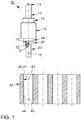
- a rotary unit 10 is shown schematically, the compactness of the structure of the rotary unit 10 with the rotary drive 13, here designed as a hollow shaft motor 13a, being clearly visible.
- a slip ring transmitter 16 is provided radially on the very outside, by means of which power current can be transmitted to the coating lance 30.
- the coating material feed 11 is provided centrally, into which (according to this illustration from above) coating material for the coating lance 30 can be fed.
- a process media feed 12 is arranged surrounding the coating material feed 11 and radially inside the hollow shaft motor 13 a, for example for process gas and / or cooling water.
- the tool holder 14 is provided below the slip ring transmitter 16 coaxially and rotatably by the hollow shaft motor 13a.
- an (optional) reading device 20 the (optional) zero point marking 19 also being arranged on the reading device 20 here.
- the introduced coating lance 30 has a corresponding zero point 32.
- the zero point 32 is aligned with the zero point marking 19.
- the coating lance 30 advantageously has an identification unit 31, for example an RFID chip, so that the coating lance 30 used can be identified automatically by means of the reading device 20.
- the coating lance 30 is shown here aligned with the cylinder axis 45 and emerged from the interior 40 to be coated, here a cylinder bore 41 of a cylinder crankcase 42, and applied the desired coating 44 to the cylinder running surface 43 there.
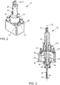
- FIGS. 2 and 3 a possible embodiment of a rotation unit 10 is shown, wherein in Fig. 2 the rotation unit 10 in a perspective view without the coating lance 30 and in FIG Fig. 3 the rotation unit 10 is shown in a perspective sectional view with the coating lance 30.
- a housing 22 and stationary supply connections are shown, namely a first supply connection 24 for coating material, preferably in powder or wire form, a second supply connection 25 for, for example, cooling water, a third supply connection 26, for example for process gas, and a fourth Supply connection 27, for example for power current for the slip ring assembly 16.
- the housing 22 is primarily used to keep the necessary bearing spacing ready to support the high rotational speed of the coating lance 30.
- the entire rotation unit 10 is connected to this housing 22 with a portal or a robot.
- a suction device 17 is provided on the housing, of which the suction connection in Fig. 2 is characterized, and wherein the suction device 17 (optional) by an air nozzle 18 (cf. Fig. 3 ) is supported.
- the component which includes the supply connections 24 to 26 and the housing 22 are stationary and therefore are not rotated about the axis of rotation 15. Only the centrally arranged components including the tool holder 14 and the coating lance 30 can be rotated about the axis of rotation 15.
- the first supply connection 24 has a (known) sealed and encapsulated roller bearing 21, for example according to the SPS Series from DSTI.
- the housing 22 has a fastening connection 28, by means of which the rotation unit 10 is mounted in a coating lance device 100 (cf. Fig. 4 ) can be moved horizontally and vertically.
- a coating lance device 100 cf. Fig. 4
- the inside 40 immersible coating nozzle 33 and a coating jet 34 shown schematically.
- a lance connection 35 is shown in the immediate vicinity of the (optional) reading device 20, for example an RFID reading device.
- a simplified coating lance device 100 is shown, in which two rotation units 10, each with a coating lance 30 by means of a lifting actuator 23 in a portal along a horizontal axis and a vertical axis, a workpiece table 46, for example for a cylinder crankcase 42 (cf. Fig. 1 ), can be supplied. Only one rotation unit 10 is shown here, and for a second, preferably structurally identical, rotation unit, the mating connection 47 for the fastening connection 28 (cf. Fig. 3 ) of the housing 22.
- the rotation unit proposed here allows low-vibration or vibration-free operation at high speeds for a coating lance for thermal coating.
- List of reference symbols 10 Rotation unit 43 Cylinder surface 11 Coating material feed 44 Coating 12th Process media supply 45 Cylinder axis 13th Rotary drive 46 Workpiece table 13a Hollow shaft motor 47 Mating connection for one 14th Tool holder Mounting connection 15th Axis of rotation 100 Coating lance device 16 Slip ring assemblies 17th Suction device 18th Air nozzle 19th Zero point marking 20th Reading device 21 roller bearing 22nd casing 23 Stroke actuator 24 first supply connection for Coating material 25th second supply connection for cooling water 26th third supply connection for Process gas 27 fourth supply connection for Power current 28 Mounting connection 30th Coating lance 31 Identification unit 32 Zero point 33 Coating nozzle 34 Coating beam 35 Lance connection 40 inner space 41 Cylinder bore 42 Cylinder crankcase
Landscapes
- Engineering & Computer Science (AREA)
- Chemical & Material Sciences (AREA)
- Physics & Mathematics (AREA)
- Mechanical Engineering (AREA)
- Plasma & Fusion (AREA)
- Combustion & Propulsion (AREA)
- General Engineering & Computer Science (AREA)
- Chemical Kinetics & Catalysis (AREA)
- Materials Engineering (AREA)
- Metallurgy (AREA)
- Organic Chemistry (AREA)
- Electromagnetism (AREA)
- Coating By Spraying Or Casting (AREA)
- Nozzles (AREA)
Description
- Die Erfindung betrifft eine Rotationseinheit für eine Beschichtungslanzeneinrichtung gemäß dem Oberbegriff des Anspruchs 1 und eine Beschichtungslanzeneinrichtung gemäß dem Oberbegriff des Anspruchs 7 zum thermischen Beschichten eines Innenraums, bevorzugt einer Zylinderbohrung eines Zylinderkurbelgehäuses.
- In der Fertigung von Zylinderkurbelgehäusen wird mehr und mehr auf Leichtbau gesetzt. Dazu werden Aluminium-Zylinderkurbelgehäuse eingesetzt, die allerdings im Bereich der Zylinderlaufbahn eine reibungsreduzierte Beschichtung benötigen, insbesondere wenn die Zylinderköpfe ebenfalls aus Aluminium gefertigt sind. Ein etabliertes Beschichtungsverfahren ist das thermische Beschichten, zum Beispiel Plasmaspritzen. Positive Effekte dieser Beschichtung sind neben einer Robustheitssteigerung der Zylinderlaufbahn eine deutlich reduzierte Reibung im Bereich der Kolbengruppe mit der Folge einer Senkung des Kohlenstoffdioxidausstoßes und ein guter Schutz gegen korrosive Medien.
- Gängige thermische Beschichtungsverfahren sind das Pulver-Plasmaspritzen, Drahtspritzverfahren wie Plasma-Transfer-Wire-Arc (PTWA) und Lichtbogen-Draht-Spritzen (LDS) oder HVOF-Spritzen (Hochgeschwindigkeitsflammspritzen). Aufgrund der beengten Verhältnisse beim Beschichten einer Zylinderlaufbahn einer Zylinderbohrung werden rotierende Beschichtungslanzen eingesetzt, welche axial in die Zylinderbohrung einführbar sind.
- Eine solche Beschichtungslanze ist beispielsweise aus
WO 2016/015 922 A1 , die sich mit einer Vorrichtung und einem Verfahren zur metallischen Beschichtung sowie einer Aufnahmeeinheit für diese Vorrichtung befasst, zum Beispiel auf Seite 2, erster bis dritter Absatz, bekannt. - In der
DE 10 2011 114 395 A1 ist eine Vorrichtung zum thermischen Beschichten von Innenwänden von Hohlkörpern beschrieben, bei der das Beschichtungsmaterial in Form von zwei Drähten von der Nachschubeinrichtung durch den um seine Längsachse drehbaren hohlen Brennerschaft und den Innenbrenner bis zum Brennerkopf des Innenbrenners führbar ist. - Die
GB 2 079 637 A - Aus der
US 2,168,807 ist eine Metall-Sprühpistole aus bekannt, bei der ein nicht näher dargestellter Draht über die Hohlwelle eines Motors zu einer koaxial rotierenden Düse gefördert wird, wobei der Düsenausgang nicht beschrieben oder gezeigt ist. - Derzeit gibt es keine Rotationseinheit für eine Beschichtungslanzeneinrichtung zum thermischen Beschichten eines Innenraums mit Drehdurchführung für Gas, Kühlwasser und Spritzgut, welche den industriellen Ansprüchen der Großserienfertigung von Zylinderkurbelgehäusen entspricht.
- Aktuell wird eine Rotationseinheit von der Firma Oerlikon Metco angeboten. Hierbei ist der Rotationsantrieb als Riementrieb ausgebildet. Maximale Drehzahlen liegen bei derzeit 250 Umdrehungen pro Minute bis bei neueren Entwicklungen maximal 800 U/min. Die Drehzahl ist dabei infolge der Riemenspannung und daraus folgender Schwingungen begrenzt.
- Der Erfindung liegt die Aufgabe zugrunde, bei einer Rotationseinheit der eingangs genannten Art die bewegte Masse der gesamten Beschichtungslanzeneinrichtung zu reduzieren und die Drehzahl schwingungsfrei zu steigern, weil überlagernde Schwingungen das Schichtergebnis stark beeinflussen und die Standzeit der eingesetzten Verfahreinheit, zum Beispiel eines Roboters oder Portals, stark reduzieren. Weiterhin ist es die Aufgabe, die Anschaffungskosten, Betriebskosten sowie Herstellungskosten zu senken.
- Diese Aufgabe wird durch die im Anspruch 1 angegebenen Merkmale gelöst, nämlich indem der Rotationsantrieb als Hohlwellenmotor koaxial zu der Rotationsachse der Werkzeugaufnahme ausgeführt ist, und wobei die Werkzeugaufnahme und die Beschichtungsmaterialzuführung sowie die Prozessmedienzuführung zentral zu dem Hohlwellenmotor angeordnet sind.
- Weiterhin wird mittels der im Anspruch 6 angegebenen Merkmale eine Reduzierung der mitbewegten Masse erreicht, nämlich, indem eine Rotationseinheit der hier vorgeschlagenen Art eingesetzt wird.
- Vorteilhafte Ausgestaltungen der Erfindung sind in den Unteransprüchen gekennzeichnet.
- Gemäß einer ersten Ausführungsform der Erfindung wird eine Rotationseinheit für eine Beschichtungslanzeneinrichtung zum thermischen Beschichten eines Innenraums, bevorzugt einer Zylinderbohrung eines Zylinderkurbelgehäuses, vorgeschlagen, wobei die Rotationseinheit zumindest die folgenden Komponenten aufweist:
- eine Werkzeugaufnahme für eine Beschichtungslanze mit einer Rotationsachse;
- ein Rotationsantrieb zum Rotieren der Werkzeugaufnahme um die Rotationsachse;
- eine Beschichtungsmaterialzuführung zum Versorgen der Beschichtungslanze mit einem Beschichtungsmaterial;
- eine Prozessmedienzuführung zum Bereitstellen von Prozessmedien zum Beschichten eines Innenraums mittels einer in der Werkzeugaufnahme aufgenommenen Beschichtungslanze.
- Die Rotationseinheit ist vor allem dadurch gekennzeichnet, dass der Rotationsantrieb als Hohlwellenmotor koaxial zu der Rotationsachse der Werkzeugaufnahme ausgeführt ist, wobei die Werkzeugaufnahme und die Beschichtungsmaterialzuführung sowie der Prozessmedienzuführung zentral zu dem Hohlwellenmotor angeordnet sind.
- Die vorgeschlagene Rotationseinheit weist im Unterschied zu den vorbekannten Ausführungsformen einen Hohlwellenmotor als Rotationsantrieb auf. Dies hat den Vorteil, dass sämtliche Medien (Gase, Kühlwasser, Beschichtungsmaterial und Leistungsstrom) zentral zugeführt werden können. Etwaige entstehende Schwingungen sind daher allein von der Auswuchtungsgüte der zentral angeordneten und mitrotiernden Komponenten abhängig. Folglich sind sehr hohe Drehzahlen, zum Beispiel 150 Umdrehungen pro Minute bis 900 Umdrehungen pro Minute, oder sogar bis zu 1000 Umdrehungen pro Minute, erreichbar. Hierdurch wird die Herstellungszeit verkürzt. Darüber hinaus ist der gesamte Aufbau der Rotationseinheit dadurch mit einer geringeren Masse ausführbar. Hierdurch ist ein Positionieren der Rotationseinheit beziehungsweise der Beschichtungslanze, welche in der Werkzeugaufnahme aufgenommen ist, mit geringeren Aktorkräften ermöglicht. Alternativ oder ergänzend ist ein Positionieren und Zustellen der Rotationseinheit mit geringerem Zeitaufwand und/oder weniger Schwingungen, welche infolge von Massenträgheitsmomenten induziert werden, ermöglicht. Zudem sind die induzierten Schwingungen in das Ausrichtsystem aufgrund der Verringerung der Schwingungen beim Betrieb der Rotationseinheit verringert.
- Die Werkzeugaufnahme ist wie aus dem Stand der Technik bekannt zur Aufnahme einer Beschichtungslanze eingerichtet. Die Werkzeugaufnahme wird von dem Rotationsantrieb um ihre Rotationsachse rotiert. Die Werkzeugaufnahme weist zudem entsprechende Medienauslässe auf, welche mit den Medieneinlässen der jeweiligen Beschichtungslanze korrespondieren. Die Medienauslässe der Werkzeugaufnahme sind mit einer Beschichtungsmaterialzuführung und einer Prozessmedienzuführung sowie einer Leistungsstromzuführung für die Beschichtungslanze eingerichtet. Diese sind zentral zu dem Hohlwellenmotor angeordnet und rotieren mit der Werkzeugaufnahme, oder diese stehen und sind über eine entsprechende Lagerung dem jeweiligen Auslass verbunden. Gemäß einer besonders bevorzugten Ausführungsform wird beispielsweise das Beschichtungsmaterial durch eine zentrale Beschichtungsmaterialzuführung, die Prozessmedien durch eine radial außerhalb, bevorzugt umlaufend umgebend, angeordnete Prozessmedienzuführung bereitgestellt, welche mit der Werkzeugaufnahme fest, also mitrotierend, verbunden sind. Diese Komponenten sind alle koaxial zueinander angeordnet. Der Hohlwellenmotor ist dabei zumindest über einen axialen Abschnitt der Prozessmedienzuführung angeordnet und wirkt auf einen mit der Prozessmedienzuführung fest verbundenen Rotor, bevorzugt den Anker, ein. Die koaxiale Anordnungsreihenfolge von Beschichtungsmaterialzuführung und den Prozessmedienzuführungen ist frei wählbar. Allerdings ist es vorteilhaft, die Beschichtungsmaterialführung zentral anzuordnen, weil das Beschichtungsmaterial der angeschlossenen Beschichtungslanze so ohne großen Aufwand zentral zuführbar ist.
- Der Aufbau ist insgesamt deutlich weniger komplex und weist eine deutlich geringere Anzahl an Einzelteilen auf, sodass die Anschaffungskosten für eine solche Rotationseinheit gesenkt sind. Außerdem ist die Masse einer solchen Rotationseinheit gegenüber einer Rotationseinheit mit Riemenantrieb deutlich reduziert, sodass die mit bewegte Masse für das Positionieren der Rotationseinheit relativ zu einem Werkstück beziehungsweise dem zu beschichtenden Innenraum reduziert ist.
- In einer vorteilhaften Ausführungsform der Rotationseinheit ist ein Schleifringübertrager zum Übertragen von elektrischem Leistungsstrom auf die Beschichtungslanze radial außerhalb des Hohlwellenmotors angeordnet.
- In dieser Ausführungsform ist ein Schleifringübertrager zur Versorgung des Brenners der Beschichtungslanze mit elektrischem Leistungsstrom vorgesehen. Der Hohlwellenmotor ist bevorzugt bürstenlos ausgeführt.
- In einer vorteilhaften Ausführungsform der Rotationseinheit ist eine Absaugeinrichtung zum Abführen von Schleifabrieb des Schleifringübertragers vorgesehen, und bevorzugt ist weiterhin zumindest eine Luftdüse vorgesehen, mittels welcher ein Abführen des Schleifabriebs unterstützbar ist.
- Bei dieser Ausführungsform wird vorgeschlagen eine Absaugeinrichtung vorzusehen, um anfallenden Schleifabrieb zielgerichtet abzuführen. Hierbei ist bevorzugt zumindest eine Luftdüse vorgesehen, welche aber nicht mehr Volumen zuführt, als über die Absaugeinrichtung abgeführt wird. Hierdurch ist eine Abschirmung anfallenden Schleifabriebs von dem thermischen Beschichtungsprozess ausreichend sichergestellt. Nach dem Stand der Technik werden Universalkupplungen eingesetzt wobei Stromübertrager starken Abrieb erzeugen, welcher mit Druckluft abgeblasen wird und somit zu Verunreinigungen in der Beschichtung führen kann. Durch die Ablagerung von leitenden Stäuben besteht die Möglichkeit eines Lichtbogenüberschlags mit der Gefahr der Zerstörung der Rotationseinheit.
- In einer vorteilhaften Ausführungsform der Rotationseinheit ist die Werkzeugaufnahme zum Aufnehmen unterschiedlicher Beschichtungslanzen eingerichtet und weist bevorzugt eine Nullpunktmarkierung zum wiederholgenauen Ausrichten einer jeweiligen Beschichtungslanze auf und umfasst besonders bevorzugt eine Leseeinrichtung zum Auslesen einer Identifikationsinformation der jeweils aufgenommenen Beschichtungslanze.
- Hier wird nun vorgeschlagen, eine Nullpunktmarkierung vorzusehen, sodass unterschiedlichste Beschichtungslanzen leicht erkennbar und überprüfbar korrekt eingesetzt werden können. Besonders bevorzugt weist die Werkzeugaufnahme einen genormten Anschluss oder mehrere Adapter für verschiedene Anschlüsse verschiedener Beschichtungslanzentypen auf.
- Ganz besonders bevorzugt ist die Werkzeugaufnahme mit einer Leseeinrichtung ausgestattet,, bevorzugt einer elektronischen Leseeinrichtung, und die Beschichtungslanze weist eine auslesbare Identifikationseinheit auf, beispielsweise einen RFID-Chip. Dieser Identifikationseinheit können Informationen zu der Beschichtungslanze entnommen werden und die Beschichtungslanze kann dadurch korrekt positioniert und betrieben werden. Alternativ ist im Betriebssystem mittels welchem die Rotationseinheit gesteuert wird, ein Zugriff auf gespeicherte Daten ermöglicht, sodass die Beschichtungslanze entsprechend ihrem Typ und/oder ihrer individuellen (historischen) Eigenschaften korrekt betreibbar ist. Auch können diese Identifikationseinheit oder die zugeordnet gespeicherten Informationen im Betriebssystem Anleitungen für den Werker zur korrekten Montage dieser Beschichtungslanze in der Werkzeugaufnahme enthalten. Hierdurch kann eine verbesserte Genauigkeit des Spritzabstandes und der Eintauchtiefe und weitere Parameter erreicht werden. Zur Qualitätssicherung können die Werkzeugdaten den bearbeiteten Bauteilen zugeordnet werden. Außerdem ist eine Historie erzeugbar, aus der die Betriebsstunden zuverlässig gespeichert werden können, um Erfahrungen zu sammeln, wann zukünftig vorbeugende Instandhaltung durchgeführt werden muss.
- In einer vorteilhaften Ausführungsform der Rotationseinheit ist das Beschichtungsmaterial pulverförmig bereitstellbar, und zum Einkoppeln von Beschichtungsmaterial ist zumindest ein gasdichtes und gekapseltes Wälzlager vorgesehen, wobei bevorzugt das Wälzlager zumindest teilweise aus Keramik gebildet ist.
- In einer besonders bevorzugten Ausführungsform wird das Beschichtungsmaterial pulverförmig, also für einen Pulver-Plasmaspritzen, bereitgestellt. In bisherigen Rotationseinheiten wurden hierzu dichtende Teflonhütchen oder luftgespülte Keramikscheiben eingesetzt. Solche Vorrichtungen weisen geringe Standzeiten auf. Hier wird nun vorgeschlagen, ein gasdichtes und gekapseltes Wälzlager einzusetzen, wodurch die Ankopplung verschleißarm ist. Besonders bevorzugt werden Keramikwälzkörper und/oder Keramiklaufflächen eingesetzt, sodass eine schmierfreie und dennoch verschleißarme und abriebarme Ausführungen mit hoher Standzeit ermöglicht ist. Ein gasdichtes und gekapseltes Wälzlager ist beispielsweise als Rotationseinheit (Rotary Union Solutions) von der Firma DSTI (Dynamic Sealing Technologies, Inc.), 13829 Jay Street NW, Andover, MN 55304, in den Vereinigten Staaten von Amerika unter der Produktreihe SPS Series bekannt (vergleiche https://www.dsti.com/industries, Dokument: "DSTI-SPS-Series-Catalog.pdf", veröffentlicht im 20. Mai 2015).
- Gemäß einem weiteren Aspekt der Erfindung wird eine Beschichtungslanzeneinrichtung zum thermischen Beschichten eines Innenraums, bevorzugt einer Zylinderbohrung eines Zylinderkurbelgehäuses, vorgeschlagen, wobei die Beschichtungslanzeneinrichtung zumindest die folgenden Komponenten aufweist:
- zumindest eine Rotationseinheit nach einer Ausführungsform gemäß der obigen Beschreibung;
- zumindest einen Hubaktor zum axialen und/oder lateralen Positionieren der Rotationseinheit relativ zu einem zu beschichtenden Innenraum; und
- stationäre Versorgungsanschlüsse für eine Stromzufuhr zu dem Hohlwellenmotor und die Beschichtungslanze, sowie für die Beschichtungsmaterialzuführung und für die Prozessmedienzuführung.
- Die Beschichtungslanzeneinrichtung weist eine Rotationseinheit auf, welche sich durch einen einfachen Aufbau und eine geringe Masse und geringe rotationsbedingte Schwingungen im Betrieb kennzeichnet. Daraus folgen geringere Haltekräfte und Positionierkräfte. Zudem werden deutlich höhere Standzeiten durch geringere Schwingungsbelastungen für die Positioniereinheit erreicht. Das Gehäuse kann zum Halten der Rotationseinheit an einem Hubaktor eingerichtet sein. Darüber hinaus ist bevorzugt eine Prozessbox vorgesehen, welche derart eingerichtet ist, dass sie einen Aufnahmeraum für die Beschichtungslanze im ausgetauchten Zustand bildet, also wenn weiterhin ein Beschichtungsstrahl erzeugt wird, aber keine Beschichtung eines Werkstücks vorgenommen werden soll. Darüber hinaus weist die Beschichtungsleistungseinrichtung die entsprechenden Anschlüsse zum Betreiben der Rotationseinheit und der Beschichtungslanze auf, wobei diese allein horizontal oder vertikal oder gar nicht bewegt werden.
- Ausführungsbeispiele der Erfindung werden nachstehend anhand der Zeichnung näher erläutert. Es zeigen
- Fig. 1
- in einer schematischen Darstellung eine Rotationseinheit mit einem Zylinderkurbelgehäuse,
- Fig. 2
- in einer perspektivischen Ansicht eine Rotationseinheit ohne Beschichtungslanze,
- Fig. 3
- in einer perspektivischen Schnittansicht eine Rotationseinheit mit Beschichtungslanze, und
- Fig. 4
- in einer perspektivischen Ansicht eine Beschichtungslanzeneinrichtung.
- In
Fig. 1 ist eine Rotationseinheit 10 schematisch dargestellt, wobei hier die Kompaktheit des Aufbaus der Rotationseinheit 10 mit dem Rotationsantrieb 13, hier als Hohlwellenmotor 13a ausgeführt, gut zu erkennen ist. Radial ganz außen ist ein Schleifringübertrager 16 vorgesehen, mittels welchem Leistungsstrom aufdie Beschichtungslanze 30 übertragbar ist. Bezogen auf die gemeinsame Rotationsachse 15 ist hierbei zentral die Beschichtungsmaterialzuführung 11 vorgesehen, in welche (nach dieser Darstellung von oben) Beschichtungsmaterial für die Beschichtungslanze 30 zuführbar ist. Die Beschichtungsmaterialzuführung 11 umgebend und radial innerhalb des Hohlwellenmotors 13a ist eine Prozessmedienzuführung 12 angeordnet, beispielsweise für Prozessgas und/oder Kühlwasser. Unterhalb des Schleifringübertragers 16 ist koaxial und von dem Hohlwellenmotor 13a rotierbar die Werkzeugaufnahme 14 vorgesehen. Dieser ist in diesem Beispiel eine (optionale) Leseeinrichtung 20 nachgeschaltet, wobei hier auch die (optionale) Nullpunktmarkierung 19 auf der Leseeinrichtung 20 angeordnet ist. Die eingeführte Beschichtungslanze 30 weist einen korrespondierenden Nullpunkt 32 auf. Der Nullpunkt 32 ist zur Nullpunktmarkierung 19 ausgerichtet. Weiterhin weist die Beschichtungslanze 30 vorteilhafterweise eine Identifikationseinheit 31 auf, beispielsweise einen RFID-Chip, sodass die eingesetzte Beschichtungslanze 30 mittels der Leseeinrichtung 20 automatisiert erkennbar ist. Die Beschichtungslanze 30 ist hier zur Zylinderachse 45 ausgerichtet dargestellt und wurde aus dem zu beschichtenden Innenraum 40, hier eine Zylinderbohrung 41 eines Zylinderkurbelgehäuses 42, wieder aufgetaucht und hat dort auf der Zylinderlauffläche 43 die gewünschte Beschichtung 44 aufgebracht. - In
Fig. 2 und Fig. 3 ist eine mögliche Ausführungsform einer Rotationseinheit 10 gezeigt, wobei inFig. 2 die Rotationseinheit 10 in einer perspektivischen Ansicht ohne Beschichtungslanze 30 und inFig. 3 die Rotationseinheit 10 in einer perspektivischen Schnittansicht mit Beschichtungslanze 30 gezeigt ist. Hierbei ist ein Gehäuse 22 und stationäre Versorgungsanschlüsse gezeigt, nämlich einem ersten Versorgungsanschluss 24 für Beschichtungsmaterial, bevorzugt pulverförmig oder drahtförmig, einem zweiten Versorgungsanschluss 25 für zum Beispiel Kühlwasser, einem dritten Versorgungsanschluss 26, für zum Beispiel Prozessgas, und einem vierten Versorgungsanschluss 27, für zum Beispiel Leistungsstrom für den Schleifringübertrager 16. Das Gehäuse 22 dient hierbei vornehmlich dem Bereithalten eines erforderlichen Lagerabstands zur Abstützung der hohen Rotationsgeschwindigkeit der Beschichtungslanze 30. Außerdem wird die gesamte Rotationseinheit 10 an diesem Gehäuse 22 mit einem Portal oder einem Roboter verbunden. Weiterhin ist an dem Gehäuse eine Absaugeinrichtung 17 vorgesehen, von welchem der Absauganschluss inFig. 2 gekennzeichnet ist, und wobei die Absaugeinrichtung 17 (optional) von einer Luftdüse 18 (vergleicheFig. 3 ) unterstützt ist. Es sei hier darauf hingewiesen, dass das Bauteil, welches die Versorgungsanschlüsse 24 bis 26 umfasst sowie das Gehäuse 22 stationär sind, und also nicht um die Rotationsachse 15 rotiert werden. Allein die zentral angeordneten Komponenten einschließlich zur Werkzeugaufnahme 14 und die Beschichtungslanze 30 sind um die Rotationsachse 15 rotierbar. Dazu weist beispielsweise der erste Versorgungsanschluss 24 ein (bekanntes) abgedichtetes und gekapseltes Wälzlager 21 auf, beispielsweise gemäß der SPS Series von der Firma DSTI. Das Gehäuse 22 weist einen Befestigungsanschluss 28 auf, mittels dessen die Rotationseinheit 10 in einer Beschichtungslanzeneinrichtung 100 (vergleicheFig. 4 ) horizontal und vertikal bewegbar ist. In der Darstellung unten an der Beschichtungslanze 30 ist die in einen Innenraum 40 (vergleicheFig. 1 ) eintauchbare Beschichtungsdüse 33 und schematisch ein Beschichtungsstrahl 34 dargestellt. In der Darstellung am oberen Ende der Beschichtungslanze 30 bei der Werkzeugaufnahme 14 ist ein Lanzenanschluss 35 in unmittelbarer Nähe zu der (optionalen) Leseeinrichtung 20, beispielsweise ein RFID-Lesegerät, dargestellt. - In
Fig. 4 ist eine vereinfachte Beschichtungslanzeneinrichtung 100 gezeigt, bei welcher zwei Rotationseinheiten 10 mit jeweils einer Beschichtungslanze 30 mittels eines Hubaktors 23 in einem Portal entlang einer horizontalen Achse und einer vertikalen Achse einem Werkstücktisch 46, beispielsweise für ein Zylinderkurbelgehäuse 42 (vergleicheFig. 1 ), zuführbar sind. Hierbei ist nur eine Rotationseinheit 10 dargestellt und für eine zweite, bevorzugt baugleiche, Rotationseinheit der Gegenanschluss 47 für den Befestigungsanschluss 28 (vergleicheFig. 3 ) des Gehäuses 22. - Die hier vorgeschlagene Rotationseinheit erlaubt einen schwingungsarmen oder schwingungsfreien Betrieb bei hohen Drehzahlen für eine Beschichtungslanze zum thermischen Beschichten.
Bezugszeichenliste 10 Rotationseinheit 43 Zylinderlauffläche 11 Beschichtungsmaterialzuführung 44 Beschichtung 12 Prozessmedienzuführung 45 Zylinderachse 13 Rotationsantrieb 46 Werkstücktisch 13a Hohlwellenmotor 47 Gegenanschluss für einen 14 Werkzeugaufnahme Befestigungsanschluss 15 Rotationsachse 100 Beschichtungslanzeneinrichtung 16 Schleifringübertrager 17 Absaugeinrichtung 18 Luftdüse 19 Nullpunktmarkierung 20 Leseeinrichtung 21 Wälzlager 22 Gehäuse 23 Hubaktor 24 erster Versorgungsanschluss für Beschichtungsmaterial 25 zweiter Versorgungsanschluss für Kühlwasser 26 dritter Versorgungsanschluss für Prozessgas 27 vierter Versorgungsanschluss für Leistungsstrom 28 Befestigungsanschluss 30 Beschichtungslanze 31 Identifikationseinheit 32 Nullpunkt 33 Beschichtungsdüse 34 Beschichtungsstrahl 35 Lanzenanschluss 40 Innenraum 41 Zylinderbohrung 42 Zylinderkurbelgehäuse
Claims (7)
- Rotationseinheit (10) für eine Beschichtungslanzeneinrichtung (100) zum thermischen Beschichten eines Innenraums (40) aufweisend zumindest die folgenden Komponenten:- eine Werkzeugaufnahme (14) für eine Beschichtungslanze (30) mit einer Rotationsachse (15);- ein Rotationsantrieb (13) zum Rotieren der Werkzeugaufnahme (14) um die Rotationsachse (15);- eine Beschichtungsmaterialzuführung (11) zum Versorgen der Beschichtungslanze (30) mit einem Beschichtungsmaterial;- eine Prozessmedienzuführung (12) zum Bereitstellen von Prozessmedien zum Beschichten eines Innenraums (40) mittels einer in der Werkzeugaufnahme (14) aufgenommenen Beschichtungslanze (30),dadurch gekennzeichnet, dass
der Rotationsantrieb (13) als Hohlwellenmotor (13a) koaxial zu der Rotationsachse (15) der Werkzeugaufnahme (14) ausgeführt ist, und wobei die Werkzeugaufnahme (14) und die Beschichtungsmaterialzuführung (11) sowie der Prozessmedienzuführung (12) zentral zu dem Hohlwellenmotor (13a) angeordnet sind. - Rotationseinheit (10) nach Anspruch 1, wobei ein Schleifringübertrager (16) zum Übertragen von elektrischem Leistungsstrom auf die Beschichtungslanze (30) radial außerhalb des Hohlwellenmotors (13a) angeordnet ist.
- Rotationseinheit (10) nach Anspruch 2, wobei eine Absaugeinrichtung (17) zum Abführen von Schleifabrieb des Schleifringübertragers (16) vorgesehen ist, und bevorzugt weiterhin zumindest eine Luftdüse (18) vorgesehen ist, mittels welcher ein Abführen des Schleifabriebs unterstützbar ist.
- Rotationseinheit (10) nach einem der vorhergehenden Ansprüche, wobei die Werkzeugaufnahme (14) zum Aufnehmen unterschiedlicher Beschichtungslanzen (30) eingerichtet ist, bevorzugt eine Nullpunktmarkierung (19) zum wiederholgenauen Ausrichten einer jeweiligen Beschichtungslanze (30) aufweist, und besonders bevorzugt eine Leseeinrichtung (20) zum Auslesen einer Identifikationsinformation der jeweils aufgenommenen Beschichtungslanze (30) umfasst.
- Rotationseinheit (10) nach einem der vorhergehenden Ansprüche, wobei das Beschichtungsmaterial pulverförmig bereitstellbar ist und zum Einkoppeln von Beschichtungsmaterial zumindest ein gasdichtes und gekapseltes sowie verschleißarmes Wälzlager (21) vorgesehen ist, wobei bevorzugt das Wälzlager (21) zumindest teilweise aus Keramik gebildet ist.
- Rotationseinheit (10) für eine Beschichtungslanzeneinrichtung (100) zum thermischen Beschichten eines Innenraums (4) nach einem der vorhergehenden Ansprüche, dadurch gekennzeichnet, dass
der Innenraum eine Zylinderbohrung eines Zylinderkurbelgehäuses ist. - Beschichtungslanzeneinrichtung (100) zum thermischen Beschichten eines Innenraums (40), bevorzugt einer Zylinderbohrung (41) eines Zylinderkurbelgehäuses (42), aufweisend zumindest die folgenden Komponenten:- zumindest eine Rotationseinheit (10) nach einem der vorhergehenden Ansprüche; - zumindest einen Hubaktor (23) zum axialen und/oder lateralen Positionieren der Rotationseinheit (10) relativ zu einem zu beschichtenden Innenraum (40); und- stationäre Versorgungsanschlüsse (24,25,26) für eine Stromzufuhr zu dem Hohlwellenmotor (13a) und der Beschichtungslanze (30), sowie für die Beschichtungsmaterialzuführung (11) und für die Prozessmedienzuführung (12).
Applications Claiming Priority (2)
| Application Number | Priority Date | Filing Date | Title |
|---|---|---|---|
| DE102017217069.7A DE102017217069A1 (de) | 2017-09-26 | 2017-09-26 | Rotationseinheit für eine Beschichtungslanzeneinrichtung zum thermischen Beschichten eines Innenraums, sowie eine solche Beschichtungslanzeneinrichtung |
| PCT/EP2018/075667 WO2019063442A1 (de) | 2017-09-26 | 2018-09-21 | Rotationseinheit mit hohlwellenmotor |
Publications (2)
| Publication Number | Publication Date |
|---|---|
| EP3687702A1 EP3687702A1 (de) | 2020-08-05 |
| EP3687702B1 true EP3687702B1 (de) | 2021-11-24 |
Family
ID=63708354
Family Applications (1)
| Application Number | Title | Priority Date | Filing Date |
|---|---|---|---|
| EP18779321.1A Active EP3687702B1 (de) | 2017-09-26 | 2018-09-21 | Rotationseinheit mit hohlwellenmotor |
Country Status (5)
| Country | Link |
|---|---|
| US (1) | US11406998B2 (de) |
| EP (1) | EP3687702B1 (de) |
| CN (1) | CN111107942B (de) |
| DE (1) | DE102017217069A1 (de) |
| WO (1) | WO2019063442A1 (de) |
Families Citing this family (5)
| Publication number | Priority date | Publication date | Assignee | Title |
|---|---|---|---|---|
| DE102019126643A1 (de) * | 2019-10-02 | 2021-04-08 | Gebr. Heller Maschinenfabrik Gmbh | Lichtbogenbrenner und Lichtbogen-Drahtspritzeinrichtung |
| DE102019126651A1 (de) * | 2019-10-02 | 2021-04-08 | Gebr. Heller Maschinenfabrik Gmbh | Lichtbogenbrenner und Lichtbogen-Drahtspritzeinrichtung |
| EP3840541A1 (de) * | 2019-12-20 | 2021-06-23 | Molecular Plasma Group SA | Verbesserte abschirmung für atmosphärendruckplasmastrahlbeschichtungsabscheidung auf einem substrat |
| CN112604850A (zh) * | 2020-12-10 | 2021-04-06 | 熊宇 | 一种空心圆柱零件内外圈防锈油均匀喷涂装置 |
| JP7705999B1 (ja) * | 2024-10-24 | 2025-07-10 | 株式会社スギノマシン | 高圧ジェット装置 |
Family Cites Families (31)
| Publication number | Priority date | Publication date | Assignee | Title |
|---|---|---|---|---|
| US2168807A (en) * | 1934-07-25 | 1939-08-08 | Schlupmann Heinrich | Metal-spraying pistol |
| US4252763A (en) * | 1978-06-06 | 1981-02-24 | Raymond International Builders, Inc. | Method and apparatus for cement lining of pipes |
| US4309958A (en) * | 1980-06-16 | 1982-01-12 | Pa Incorporated | Coating lance centralizer |
| JPS584926A (ja) | 1981-06-30 | 1983-01-12 | Nec Corp | 回転塗布装置 |
| DE3241710A1 (de) | 1982-11-11 | 1984-05-17 | Diffracto Ltd., Windsor, Ontario | Verfahren und vorrichtung zur pruefung von teilen oder werkstuecken |
| DE3919699A1 (de) | 1989-06-16 | 1991-01-03 | Isleib Hans Gerd | Werkzeug-identifikation |
| DE19501026C2 (de) | 1995-01-14 | 2001-08-09 | Drebo Werkzeugfab Gmbh | Einrichtung zur automatischen Erkennung werkzeugspezifischer Daten sowie ein Werkzeug mit einer Kodierung für werkzeugspezifische Daten |
| DE19841617A1 (de) * | 1998-09-11 | 2000-03-23 | Daimler Chrysler Ag | Rotierende Drahtlichtbogenspritzanlage zur Beschichtung von Innenflächen |
| EP1350862A1 (de) * | 2002-04-04 | 2003-10-08 | Sulzer Metco AG | Vorrichtung und Verfahren zum thermischen Beschichten einer Fläche |
| DE102005047328B3 (de) | 2005-06-28 | 2006-12-07 | Fraunhofer-Gesellschaft zur Förderung der angewandten Forschung e.V. | Vorrichtung zum Bohren und für den Materialabtrag mittels Laserstrahl |
| ATE529193T1 (de) * | 2006-07-24 | 2011-11-15 | Sulzer Metco Ag | Maskierungssystem zur maskierung eines kurbelraums einer brennkraftmaschine |
| JP5320951B2 (ja) * | 2008-10-02 | 2013-10-23 | 日産自動車株式会社 | 溶射皮膜形成装置及び溶射皮膜形成方法 |
| DE102010034921A1 (de) * | 2010-08-20 | 2012-02-23 | Dürr Systems GmbH | Düse zur Applikation eines Auftragsmittels |
| JP5602561B2 (ja) * | 2010-09-27 | 2014-10-08 | トヨタ自動車株式会社 | 静電塗装用塗装ガン |
| DE102010060652A1 (de) * | 2010-11-18 | 2012-05-24 | Martinrea Honsel Germany Gmbh | Vorrichtung für das thermische Beschichten von Zylinderinnenflächen bei Kurbelgehäusen |
| DE102011114395A1 (de) * | 2011-09-24 | 2013-03-28 | Daimler Ag | Vorrichtung zum thermischen Beschichten |
| DE102012109203B3 (de) * | 2012-09-28 | 2013-11-21 | Gebr. Heller Maschinenfabrik Gmbh | Vorrichtung und Verfahren zur Beschichtung von Zylinderbohrungen eines Motorblocks |
| US9259780B2 (en) * | 2013-03-15 | 2016-02-16 | Esm Group Inc. | Rotational lance drive and rotational lance injection method |
| US10525603B2 (en) * | 2013-08-22 | 2020-01-07 | The Boeing Company | Method and apparatus for exchanging nozzles and tips for a fluid dispensing system |
| DE102013014174A1 (de) * | 2013-08-26 | 2015-03-12 | Bayerische Motoren Werke Aktiengesellschaft | Vorrichtung zum Beschichten von Zylinderwänden |
| DE102014200633B3 (de) | 2014-01-15 | 2015-05-07 | Fraunhofer-Gesellschaft zur Förderung der angewandten Forschung e.V. | Bearbeitungsvorrichtung und -verfahren zur Laserbearbeitung einer Oberfläche |
| GB2527557A (en) * | 2014-06-25 | 2015-12-30 | Mahle Engine Systems Uk Ltd | Bearing element and sliding layer material for a bearing element |
| HUE038745T2 (hu) | 2014-07-30 | 2018-11-28 | Sturm Maschinen & Anlagenbau Gmbh | Berendezés és eljárás munkadarab fémes réteggel történõ bevonására és felvevõ egység a berendezéshez |
| CN104640339A (zh) * | 2015-01-12 | 2015-05-20 | 广东韦达尔科技有限公司 | 一种等离子表面处理装置 |
| ES2644060T3 (es) * | 2015-01-20 | 2017-11-27 | Sturm Maschinen- & Anlagenbau Gmbh | Procedimiento e instalación de revestimiento para el revestimiento de paredes de cavidad |
| HUE036369T2 (hu) * | 2015-01-20 | 2018-07-30 | Sturm Maschinen & Anlagenbau Gmbh | Vizsgálóberendezés és eljárás egy üreges test vizsgálatára |
| DE102015104492B4 (de) * | 2015-03-25 | 2024-05-08 | Gebr. Heller Maschinenfabrik Gmbh | Beschichtungsvorrichtung zur Beschichtung einer Werkstückfläche eines Werkstücks |
| CN204634143U (zh) * | 2015-06-01 | 2015-09-09 | 烟台金鹰科技有限公司 | 一体型等离子旋转喷枪 |
| ITUB20159465A1 (it) | 2015-12-16 | 2017-06-16 | Turbocoating S P A | Metodo di deposizione thermal spray di un ricoprimento su una superficie e apparato |
| CN206424088U (zh) * | 2016-10-13 | 2017-08-22 | 上海联影医疗科技有限公司 | 滑环系统及ct设备 |
| CN107164715B (zh) * | 2017-06-09 | 2019-03-26 | 华晨宝马汽车有限公司 | 用于电弧丝材喷涂的方法、设备及产品 |
-
2017
- 2017-09-26 DE DE102017217069.7A patent/DE102017217069A1/de not_active Withdrawn
-
2018
- 2018-09-21 CN CN201880062723.0A patent/CN111107942B/zh active Active
- 2018-09-21 WO PCT/EP2018/075667 patent/WO2019063442A1/de not_active Ceased
- 2018-09-21 EP EP18779321.1A patent/EP3687702B1/de active Active
-
2020
- 2020-03-26 US US16/831,171 patent/US11406998B2/en active Active
Also Published As
| Publication number | Publication date |
|---|---|
| WO2019063442A1 (de) | 2019-04-04 |
| US20200222931A1 (en) | 2020-07-16 |
| CN111107942B (zh) | 2022-05-24 |
| CN111107942A (zh) | 2020-05-05 |
| DE102017217069A1 (de) | 2019-03-28 |
| US11406998B2 (en) | 2022-08-09 |
| EP3687702A1 (de) | 2020-08-05 |
Similar Documents
| Publication | Publication Date | Title |
|---|---|---|
| EP3687702A1 (de) | Rotationseinheit mit hohlwellenmotor | |
| EP2741862B1 (de) | Vorrichtung zum erzeugen eines pulsierenden mit druck beaufschlagten fluidstrahls | |
| DE4240991A1 (de) | Plasmaspritzgerät | |
| WO2004005575A2 (de) | Verfahren und vorrichtung zur innenbeschichtung von hohlräumen durch thermisches spritzen | |
| EP1690601B1 (de) | Vorrichtung zum thermischen Spritzen | |
| WO2021151131A1 (de) | Verfahren zum hochgeschwindigkeitsbeschichten der innenfläche eines rohlings | |
| EP2427298A1 (de) | Laserstation und laseranlage | |
| EP2106456A2 (de) | Verfahren und vorrichtung zum beschichten eines hohlkörpers | |
| EP3048182B1 (de) | Anlage und Verfahren zur metallischen Beschichtung eines Werkstücks | |
| EP3152000B1 (de) | Finishvorrichtung zur finishbearbeitung eines werkstücks, insbesondere einer kurbelwelle oder einer nockenwelle | |
| EP3039169A1 (de) | Vorrichtung zum beschichten von zylinderwänden | |
| EP0564842A1 (de) | Werkzeugmaschine mit Drehtisch | |
| CH656560A5 (de) | Verfahren zum auftragen einer schutzschicht durch thermisches spritzen. | |
| EP1942387A1 (de) | Beschichtungskonzept für eine APS/HVOF Anlage mit 2 Robotern | |
| EP2933352B1 (de) | Anlage und Verfahren zur metallischen Beschichtung einer Bohrungswand | |
| DE102018104199A1 (de) | Werkzeugmaschine mit Arbeitsraum, Rüstplatz und Roboterarm und Verfahren zu deren Betrieb | |
| DE202018102990U1 (de) | Adapter für Laserschneidköpfe | |
| EP1127652A1 (de) | Verfahren und Vorrichtung zum Bearbeiten einer Innenfläche einer zylinderförmigen Bohrung mittels Laser und gekühlter Umlenkoptik | |
| WO2013083672A1 (de) | Plasmaspritzgerät, sowie beschichtungsverfahren | |
| DE202011104249U1 (de) | Vorrichtung zum Erzeugen eines pulsierenden mit Druck beaufschlagten Fluidstrahls | |
| WO2024217787A1 (de) | Rotor für eine fremderregte synchronmaschine | |
| EP3009203A1 (de) | Verfahren und vorrichtung zum abtragen einer innenbeschichtung von hohlkörpern | |
| EP1291131B1 (de) | Vorrichtung zum abwechselnden Bearbeiten eines Werkstückes mittels eines Schleifwerkzeuges oder einer Funkenerosionelektrode | |
| EP1350862A1 (de) | Vorrichtung und Verfahren zum thermischen Beschichten einer Fläche | |
| DE102009035679B4 (de) | Aufspanneinrichtung und Bearbeitungseinrichtung |
Legal Events
| Date | Code | Title | Description |
|---|---|---|---|
| STAA | Information on the status of an ep patent application or granted ep patent |
Free format text: STATUS: UNKNOWN |
|
| STAA | Information on the status of an ep patent application or granted ep patent |
Free format text: STATUS: THE INTERNATIONAL PUBLICATION HAS BEEN MADE |
|
| PUAI | Public reference made under article 153(3) epc to a published international application that has entered the european phase |
Free format text: ORIGINAL CODE: 0009012 |
|
| STAA | Information on the status of an ep patent application or granted ep patent |
Free format text: STATUS: REQUEST FOR EXAMINATION WAS MADE |
|
| 17P | Request for examination filed |
Effective date: 20200428 |
|
| AK | Designated contracting states |
Kind code of ref document: A1 Designated state(s): AL AT BE BG CH CY CZ DE DK EE ES FI FR GB GR HR HU IE IS IT LI LT LU LV MC MK MT NL NO PL PT RO RS SE SI SK SM TR |
|
| AX | Request for extension of the european patent |
Extension state: BA ME |
|
| DAV | Request for validation of the european patent (deleted) | ||
| DAX | Request for extension of the european patent (deleted) | ||
| GRAP | Despatch of communication of intention to grant a patent |
Free format text: ORIGINAL CODE: EPIDOSNIGR1 |
|
| STAA | Information on the status of an ep patent application or granted ep patent |
Free format text: STATUS: GRANT OF PATENT IS INTENDED |
|
| INTG | Intention to grant announced |
Effective date: 20210720 |
|
| GRAS | Grant fee paid |
Free format text: ORIGINAL CODE: EPIDOSNIGR3 |
|
| GRAA | (expected) grant |
Free format text: ORIGINAL CODE: 0009210 |
|
| STAA | Information on the status of an ep patent application or granted ep patent |
Free format text: STATUS: THE PATENT HAS BEEN GRANTED |
|
| AK | Designated contracting states |
Kind code of ref document: B1 Designated state(s): AL AT BE BG CH CY CZ DE DK EE ES FI FR GB GR HR HU IE IS IT LI LT LU LV MC MK MT NL NO PL PT RO RS SE SI SK SM TR |
|
| REG | Reference to a national code |
Ref country code: GB Ref legal event code: FG4D Free format text: NOT ENGLISH |
|
| REG | Reference to a national code |
Ref country code: AT Ref legal event code: REF Ref document number: 1449444 Country of ref document: AT Kind code of ref document: T Effective date: 20211215 |
|
| REG | Reference to a national code |
Ref country code: DE Ref legal event code: R096 Ref document number: 502018007989 Country of ref document: DE |
|
| REG | Reference to a national code |
Ref country code: IE Ref legal event code: FG4D Free format text: LANGUAGE OF EP DOCUMENT: GERMAN |
|
| REG | Reference to a national code |
Ref country code: LT Ref legal event code: MG9D |
|
| REG | Reference to a national code |
Ref country code: NL Ref legal event code: MP Effective date: 20211124 |
|
| PG25 | Lapsed in a contracting state [announced via postgrant information from national office to epo] |
Ref country code: RS Free format text: LAPSE BECAUSE OF FAILURE TO SUBMIT A TRANSLATION OF THE DESCRIPTION OR TO PAY THE FEE WITHIN THE PRESCRIBED TIME-LIMIT Effective date: 20211124 Ref country code: LT Free format text: LAPSE BECAUSE OF FAILURE TO SUBMIT A TRANSLATION OF THE DESCRIPTION OR TO PAY THE FEE WITHIN THE PRESCRIBED TIME-LIMIT Effective date: 20211124 Ref country code: FI Free format text: LAPSE BECAUSE OF FAILURE TO SUBMIT A TRANSLATION OF THE DESCRIPTION OR TO PAY THE FEE WITHIN THE PRESCRIBED TIME-LIMIT Effective date: 20211124 Ref country code: BG Free format text: LAPSE BECAUSE OF FAILURE TO SUBMIT A TRANSLATION OF THE DESCRIPTION OR TO PAY THE FEE WITHIN THE PRESCRIBED TIME-LIMIT Effective date: 20220224 |
|
| PG25 | Lapsed in a contracting state [announced via postgrant information from national office to epo] |
Ref country code: IS Free format text: LAPSE BECAUSE OF FAILURE TO SUBMIT A TRANSLATION OF THE DESCRIPTION OR TO PAY THE FEE WITHIN THE PRESCRIBED TIME-LIMIT Effective date: 20220324 Ref country code: SE Free format text: LAPSE BECAUSE OF FAILURE TO SUBMIT A TRANSLATION OF THE DESCRIPTION OR TO PAY THE FEE WITHIN THE PRESCRIBED TIME-LIMIT Effective date: 20211124 Ref country code: PT Free format text: LAPSE BECAUSE OF FAILURE TO SUBMIT A TRANSLATION OF THE DESCRIPTION OR TO PAY THE FEE WITHIN THE PRESCRIBED TIME-LIMIT Effective date: 20220324 Ref country code: PL Free format text: LAPSE BECAUSE OF FAILURE TO SUBMIT A TRANSLATION OF THE DESCRIPTION OR TO PAY THE FEE WITHIN THE PRESCRIBED TIME-LIMIT Effective date: 20211124 Ref country code: NO Free format text: LAPSE BECAUSE OF FAILURE TO SUBMIT A TRANSLATION OF THE DESCRIPTION OR TO PAY THE FEE WITHIN THE PRESCRIBED TIME-LIMIT Effective date: 20220224 Ref country code: NL Free format text: LAPSE BECAUSE OF FAILURE TO SUBMIT A TRANSLATION OF THE DESCRIPTION OR TO PAY THE FEE WITHIN THE PRESCRIBED TIME-LIMIT Effective date: 20211124 Ref country code: LV Free format text: LAPSE BECAUSE OF FAILURE TO SUBMIT A TRANSLATION OF THE DESCRIPTION OR TO PAY THE FEE WITHIN THE PRESCRIBED TIME-LIMIT Effective date: 20211124 Ref country code: HR Free format text: LAPSE BECAUSE OF FAILURE TO SUBMIT A TRANSLATION OF THE DESCRIPTION OR TO PAY THE FEE WITHIN THE PRESCRIBED TIME-LIMIT Effective date: 20211124 Ref country code: GR Free format text: LAPSE BECAUSE OF FAILURE TO SUBMIT A TRANSLATION OF THE DESCRIPTION OR TO PAY THE FEE WITHIN THE PRESCRIBED TIME-LIMIT Effective date: 20220225 Ref country code: ES Free format text: LAPSE BECAUSE OF FAILURE TO SUBMIT A TRANSLATION OF THE DESCRIPTION OR TO PAY THE FEE WITHIN THE PRESCRIBED TIME-LIMIT Effective date: 20211124 |
|
| PG25 | Lapsed in a contracting state [announced via postgrant information from national office to epo] |
Ref country code: SM Free format text: LAPSE BECAUSE OF FAILURE TO SUBMIT A TRANSLATION OF THE DESCRIPTION OR TO PAY THE FEE WITHIN THE PRESCRIBED TIME-LIMIT Effective date: 20211124 Ref country code: SK Free format text: LAPSE BECAUSE OF FAILURE TO SUBMIT A TRANSLATION OF THE DESCRIPTION OR TO PAY THE FEE WITHIN THE PRESCRIBED TIME-LIMIT Effective date: 20211124 Ref country code: RO Free format text: LAPSE BECAUSE OF FAILURE TO SUBMIT A TRANSLATION OF THE DESCRIPTION OR TO PAY THE FEE WITHIN THE PRESCRIBED TIME-LIMIT Effective date: 20211124 Ref country code: EE Free format text: LAPSE BECAUSE OF FAILURE TO SUBMIT A TRANSLATION OF THE DESCRIPTION OR TO PAY THE FEE WITHIN THE PRESCRIBED TIME-LIMIT Effective date: 20211124 Ref country code: DK Free format text: LAPSE BECAUSE OF FAILURE TO SUBMIT A TRANSLATION OF THE DESCRIPTION OR TO PAY THE FEE WITHIN THE PRESCRIBED TIME-LIMIT Effective date: 20211124 Ref country code: CZ Free format text: LAPSE BECAUSE OF FAILURE TO SUBMIT A TRANSLATION OF THE DESCRIPTION OR TO PAY THE FEE WITHIN THE PRESCRIBED TIME-LIMIT Effective date: 20211124 |
|
| REG | Reference to a national code |
Ref country code: DE Ref legal event code: R097 Ref document number: 502018007989 Country of ref document: DE |
|
| PLBE | No opposition filed within time limit |
Free format text: ORIGINAL CODE: 0009261 |
|
| STAA | Information on the status of an ep patent application or granted ep patent |
Free format text: STATUS: NO OPPOSITION FILED WITHIN TIME LIMIT |
|
| PG25 | Lapsed in a contracting state [announced via postgrant information from national office to epo] |
Ref country code: AL Free format text: LAPSE BECAUSE OF FAILURE TO SUBMIT A TRANSLATION OF THE DESCRIPTION OR TO PAY THE FEE WITHIN THE PRESCRIBED TIME-LIMIT Effective date: 20211124 |
|
| 26N | No opposition filed |
Effective date: 20220825 |
|
| PG25 | Lapsed in a contracting state [announced via postgrant information from national office to epo] |
Ref country code: SI Free format text: LAPSE BECAUSE OF FAILURE TO SUBMIT A TRANSLATION OF THE DESCRIPTION OR TO PAY THE FEE WITHIN THE PRESCRIBED TIME-LIMIT Effective date: 20211124 |
|
| PG25 | Lapsed in a contracting state [announced via postgrant information from national office to epo] |
Ref country code: MC Free format text: LAPSE BECAUSE OF FAILURE TO SUBMIT A TRANSLATION OF THE DESCRIPTION OR TO PAY THE FEE WITHIN THE PRESCRIBED TIME-LIMIT Effective date: 20211124 |
|
| REG | Reference to a national code |
Ref country code: CH Ref legal event code: PL |
|
| GBPC | Gb: european patent ceased through non-payment of renewal fee |
Effective date: 20220921 |
|
| REG | Reference to a national code |
Ref country code: BE Ref legal event code: MM Effective date: 20220930 |
|
| PG25 | Lapsed in a contracting state [announced via postgrant information from national office to epo] |
Ref country code: IT Free format text: LAPSE BECAUSE OF FAILURE TO SUBMIT A TRANSLATION OF THE DESCRIPTION OR TO PAY THE FEE WITHIN THE PRESCRIBED TIME-LIMIT Effective date: 20211124 |
|
| P01 | Opt-out of the competence of the unified patent court (upc) registered |
Effective date: 20230523 |
|
| PG25 | Lapsed in a contracting state [announced via postgrant information from national office to epo] |
Ref country code: LU Free format text: LAPSE BECAUSE OF NON-PAYMENT OF DUE FEES Effective date: 20220921 |
|
| PG25 | Lapsed in a contracting state [announced via postgrant information from national office to epo] |
Ref country code: LI Free format text: LAPSE BECAUSE OF NON-PAYMENT OF DUE FEES Effective date: 20220930 Ref country code: IE Free format text: LAPSE BECAUSE OF NON-PAYMENT OF DUE FEES Effective date: 20220921 Ref country code: FR Free format text: LAPSE BECAUSE OF NON-PAYMENT OF DUE FEES Effective date: 20220930 Ref country code: CH Free format text: LAPSE BECAUSE OF NON-PAYMENT OF DUE FEES Effective date: 20220930 |
|
| PG25 | Lapsed in a contracting state [announced via postgrant information from national office to epo] |
Ref country code: BE Free format text: LAPSE BECAUSE OF NON-PAYMENT OF DUE FEES Effective date: 20220930 |
|
| PG25 | Lapsed in a contracting state [announced via postgrant information from national office to epo] |
Ref country code: GB Free format text: LAPSE BECAUSE OF NON-PAYMENT OF DUE FEES Effective date: 20220921 |
|
| PG25 | Lapsed in a contracting state [announced via postgrant information from national office to epo] |
Ref country code: CY Free format text: LAPSE BECAUSE OF FAILURE TO SUBMIT A TRANSLATION OF THE DESCRIPTION OR TO PAY THE FEE WITHIN THE PRESCRIBED TIME-LIMIT Effective date: 20211124 |
|
| PG25 | Lapsed in a contracting state [announced via postgrant information from national office to epo] |
Ref country code: MK Free format text: LAPSE BECAUSE OF FAILURE TO SUBMIT A TRANSLATION OF THE DESCRIPTION OR TO PAY THE FEE WITHIN THE PRESCRIBED TIME-LIMIT Effective date: 20211124 Ref country code: HU Free format text: LAPSE BECAUSE OF FAILURE TO SUBMIT A TRANSLATION OF THE DESCRIPTION OR TO PAY THE FEE WITHIN THE PRESCRIBED TIME-LIMIT; INVALID AB INITIO Effective date: 20180921 |
|
| PG25 | Lapsed in a contracting state [announced via postgrant information from national office to epo] |
Ref country code: MT Free format text: LAPSE BECAUSE OF FAILURE TO SUBMIT A TRANSLATION OF THE DESCRIPTION OR TO PAY THE FEE WITHIN THE PRESCRIBED TIME-LIMIT Effective date: 20211124 |
|
| REG | Reference to a national code |
Ref country code: AT Ref legal event code: MM01 Ref document number: 1449444 Country of ref document: AT Kind code of ref document: T Effective date: 20230921 |
|
| PG25 | Lapsed in a contracting state [announced via postgrant information from national office to epo] |
Ref country code: AT Free format text: LAPSE BECAUSE OF NON-PAYMENT OF DUE FEES Effective date: 20230921 |
|
| PG25 | Lapsed in a contracting state [announced via postgrant information from national office to epo] |
Ref country code: AT Free format text: LAPSE BECAUSE OF NON-PAYMENT OF DUE FEES Effective date: 20230921 |
|
| PGFP | Annual fee paid to national office [announced via postgrant information from national office to epo] |
Ref country code: DE Payment date: 20250930 Year of fee payment: 8 |
|
| PG25 | Lapsed in a contracting state [announced via postgrant information from national office to epo] |
Ref country code: TR Free format text: LAPSE BECAUSE OF FAILURE TO SUBMIT A TRANSLATION OF THE DESCRIPTION OR TO PAY THE FEE WITHIN THE PRESCRIBED TIME-LIMIT Effective date: 20211124 |
|
| PGFP | Annual fee paid to national office [announced via postgrant information from national office to epo] |
Ref country code: AT Payment date: 20260410 Year of fee payment: 5 |