EP3687459B1 - Dispositif d'insertion d'un implant chirurgical - Google Patents
Dispositif d'insertion d'un implant chirurgical Download PDFInfo
- Publication number
- EP3687459B1 EP3687459B1 EP18785855.0A EP18785855A EP3687459B1 EP 3687459 B1 EP3687459 B1 EP 3687459B1 EP 18785855 A EP18785855 A EP 18785855A EP 3687459 B1 EP3687459 B1 EP 3687459B1
- Authority
- EP
- European Patent Office
- Prior art keywords
- implant
- impactor
- impact
- peak
- sensor
- Prior art date
- Legal status (The legal status is an assumption and is not a legal conclusion. Google has not performed a legal analysis and makes no representation as to the accuracy of the status listed.)
- Active
Links
Images

Classifications
-
- A—HUMAN NECESSITIES
- A61—MEDICAL OR VETERINARY SCIENCE; HYGIENE
- A61B—DIAGNOSIS; SURGERY; IDENTIFICATION
- A61B17/00—Surgical instruments, devices or methods
- A61B17/56—Surgical instruments or methods for treatment of bones or joints; Devices specially adapted therefor
- A61B17/58—Surgical instruments or methods for treatment of bones or joints; Devices specially adapted therefor for osteosynthesis, e.g. bone plates, screws or setting implements
- A61B17/88—Osteosynthesis instruments; Methods or means for implanting or extracting internal or external fixation devices
- A61B17/92—Impactors or extractors, e.g. for removing intramedullary devices
- A61B17/921—Impactors or extractors, e.g. for removing intramedullary devices for intramedullary devices
-
- A—HUMAN NECESSITIES
- A61—MEDICAL OR VETERINARY SCIENCE; HYGIENE
- A61F—FILTERS IMPLANTABLE INTO BLOOD VESSELS; PROSTHESES; DEVICES PROVIDING PATENCY TO, OR PREVENTING COLLAPSING OF, TUBULAR STRUCTURES OF THE BODY, e.g. STENTS; ORTHOPAEDIC, NURSING OR CONTRACEPTIVE DEVICES; FOMENTATION; TREATMENT OR PROTECTION OF EYES OR EARS; BANDAGES, DRESSINGS OR ABSORBENT PADS; FIRST-AID KITS
- A61F2/00—Filters implantable into blood vessels; Prostheses, i.e. artificial substitutes or replacements for parts of the body; Appliances for connecting them with the body; Devices providing patency to, or preventing collapsing of, tubular structures of the body, e.g. stents
- A61F2/02—Prostheses implantable into the body
- A61F2/30—Joints
- A61F2/46—Special tools for implanting artificial joints
- A61F2/4603—Special tools for implanting artificial joints for insertion or extraction of endoprosthetic joints or of accessories thereof
- A61F2/4607—Special tools for implanting artificial joints for insertion or extraction of endoprosthetic joints or of accessories thereof of hip femoral endoprostheses
-
- A—HUMAN NECESSITIES
- A61—MEDICAL OR VETERINARY SCIENCE; HYGIENE
- A61F—FILTERS IMPLANTABLE INTO BLOOD VESSELS; PROSTHESES; DEVICES PROVIDING PATENCY TO, OR PREVENTING COLLAPSING OF, TUBULAR STRUCTURES OF THE BODY, e.g. STENTS; ORTHOPAEDIC, NURSING OR CONTRACEPTIVE DEVICES; FOMENTATION; TREATMENT OR PROTECTION OF EYES OR EARS; BANDAGES, DRESSINGS OR ABSORBENT PADS; FIRST-AID KITS
- A61F2/00—Filters implantable into blood vessels; Prostheses, i.e. artificial substitutes or replacements for parts of the body; Appliances for connecting them with the body; Devices providing patency to, or preventing collapsing of, tubular structures of the body, e.g. stents
- A61F2/02—Prostheses implantable into the body
- A61F2/30—Joints
- A61F2/46—Special tools for implanting artificial joints
- A61F2/4657—Measuring instruments used for implanting artificial joints
-
- A—HUMAN NECESSITIES
- A61—MEDICAL OR VETERINARY SCIENCE; HYGIENE
- A61B—DIAGNOSIS; SURGERY; IDENTIFICATION
- A61B17/00—Surgical instruments, devices or methods
- A61B17/56—Surgical instruments or methods for treatment of bones or joints; Devices specially adapted therefor
- A61B17/58—Surgical instruments or methods for treatment of bones or joints; Devices specially adapted therefor for osteosynthesis, e.g. bone plates, screws or setting implements
- A61B17/68—Internal fixation devices, including fasteners and spinal fixators, even if a part thereof projects from the skin
- A61B17/72—Intramedullary devices, e.g. pins or nails
-
- A—HUMAN NECESSITIES
- A61—MEDICAL OR VETERINARY SCIENCE; HYGIENE
- A61B—DIAGNOSIS; SURGERY; IDENTIFICATION
- A61B17/00—Surgical instruments, devices or methods
- A61B17/56—Surgical instruments or methods for treatment of bones or joints; Devices specially adapted therefor
- A61B17/58—Surgical instruments or methods for treatment of bones or joints; Devices specially adapted therefor for osteosynthesis, e.g. bone plates, screws or setting implements
- A61B17/88—Osteosynthesis instruments; Methods or means for implanting or extracting internal or external fixation devices
- A61B17/92—Impactors or extractors, e.g. for removing intramedullary devices
-
- A—HUMAN NECESSITIES
- A61—MEDICAL OR VETERINARY SCIENCE; HYGIENE
- A61B—DIAGNOSIS; SURGERY; IDENTIFICATION
- A61B17/00—Surgical instruments, devices or methods
- A61B2017/00017—Electrical control of surgical instruments
- A61B2017/00022—Sensing or detecting at the treatment site
-
- A—HUMAN NECESSITIES
- A61—MEDICAL OR VETERINARY SCIENCE; HYGIENE
- A61B—DIAGNOSIS; SURGERY; IDENTIFICATION
- A61B17/00—Surgical instruments, devices or methods
- A61B2017/00017—Electrical control of surgical instruments
- A61B2017/00022—Sensing or detecting at the treatment site
- A61B2017/00106—Sensing or detecting at the treatment site ultrasonic
- A61B2017/0011—Sensing or detecting at the treatment site ultrasonic piezoelectric
-
- A—HUMAN NECESSITIES
- A61—MEDICAL OR VETERINARY SCIENCE; HYGIENE
- A61B—DIAGNOSIS; SURGERY; IDENTIFICATION
- A61B17/00—Surgical instruments, devices or methods
- A61B2017/00017—Electrical control of surgical instruments
- A61B2017/00115—Electrical control of surgical instruments with audible or visual output
- A61B2017/00119—Electrical control of surgical instruments with audible or visual output alarm; indicating an abnormal situation
-
- A—HUMAN NECESSITIES
- A61—MEDICAL OR VETERINARY SCIENCE; HYGIENE
- A61B—DIAGNOSIS; SURGERY; IDENTIFICATION
- A61B17/00—Surgical instruments, devices or methods
- A61B17/56—Surgical instruments or methods for treatment of bones or joints; Devices specially adapted therefor
- A61B17/58—Surgical instruments or methods for treatment of bones or joints; Devices specially adapted therefor for osteosynthesis, e.g. bone plates, screws or setting implements
- A61B17/88—Osteosynthesis instruments; Methods or means for implanting or extracting internal or external fixation devices
- A61B17/92—Impactors or extractors, e.g. for removing intramedullary devices
- A61B2017/922—Devices for impaction, impact element
-
- A—HUMAN NECESSITIES
- A61—MEDICAL OR VETERINARY SCIENCE; HYGIENE
- A61B—DIAGNOSIS; SURGERY; IDENTIFICATION
- A61B17/00—Surgical instruments, devices or methods
- A61B17/56—Surgical instruments or methods for treatment of bones or joints; Devices specially adapted therefor
- A61B17/58—Surgical instruments or methods for treatment of bones or joints; Devices specially adapted therefor for osteosynthesis, e.g. bone plates, screws or setting implements
- A61B17/88—Osteosynthesis instruments; Methods or means for implanting or extracting internal or external fixation devices
- A61B17/92—Impactors or extractors, e.g. for removing intramedullary devices
- A61B2017/922—Devices for impaction, impact element
- A61B2017/924—Impact element driving means
-
- A—HUMAN NECESSITIES
- A61—MEDICAL OR VETERINARY SCIENCE; HYGIENE
- A61B—DIAGNOSIS; SURGERY; IDENTIFICATION
- A61B90/00—Instruments, implements or accessories specially adapted for surgery or diagnosis and not covered by any of the groups A61B1/00 - A61B50/00, e.g. for luxation treatment or for protecting wound edges
- A61B90/06—Measuring instruments not otherwise provided for
- A61B2090/064—Measuring instruments not otherwise provided for for measuring force, pressure or mechanical tension
- A61B2090/065—Measuring instruments not otherwise provided for for measuring force, pressure or mechanical tension for measuring contact or contact pressure
-
- A—HUMAN NECESSITIES
- A61—MEDICAL OR VETERINARY SCIENCE; HYGIENE
- A61F—FILTERS IMPLANTABLE INTO BLOOD VESSELS; PROSTHESES; DEVICES PROVIDING PATENCY TO, OR PREVENTING COLLAPSING OF, TUBULAR STRUCTURES OF THE BODY, e.g. STENTS; ORTHOPAEDIC, NURSING OR CONTRACEPTIVE DEVICES; FOMENTATION; TREATMENT OR PROTECTION OF EYES OR EARS; BANDAGES, DRESSINGS OR ABSORBENT PADS; FIRST-AID KITS
- A61F2/00—Filters implantable into blood vessels; Prostheses, i.e. artificial substitutes or replacements for parts of the body; Appliances for connecting them with the body; Devices providing patency to, or preventing collapsing of, tubular structures of the body, e.g. stents
- A61F2/02—Prostheses implantable into the body
- A61F2/30—Joints
- A61F2/46—Special tools for implanting artificial joints
- A61F2/4657—Measuring instruments used for implanting artificial joints
- A61F2002/4658—Measuring instruments used for implanting artificial joints for measuring dimensions, e.g. length
-
- A—HUMAN NECESSITIES
- A61—MEDICAL OR VETERINARY SCIENCE; HYGIENE
- A61F—FILTERS IMPLANTABLE INTO BLOOD VESSELS; PROSTHESES; DEVICES PROVIDING PATENCY TO, OR PREVENTING COLLAPSING OF, TUBULAR STRUCTURES OF THE BODY, e.g. STENTS; ORTHOPAEDIC, NURSING OR CONTRACEPTIVE DEVICES; FOMENTATION; TREATMENT OR PROTECTION OF EYES OR EARS; BANDAGES, DRESSINGS OR ABSORBENT PADS; FIRST-AID KITS
- A61F2/00—Filters implantable into blood vessels; Prostheses, i.e. artificial substitutes or replacements for parts of the body; Appliances for connecting them with the body; Devices providing patency to, or preventing collapsing of, tubular structures of the body, e.g. stents
- A61F2/02—Prostheses implantable into the body
- A61F2/30—Joints
- A61F2/46—Special tools for implanting artificial joints
- A61F2/4657—Measuring instruments used for implanting artificial joints
- A61F2002/4666—Measuring instruments used for implanting artificial joints for measuring force, pressure or mechanical tension
-
- A—HUMAN NECESSITIES
- A61—MEDICAL OR VETERINARY SCIENCE; HYGIENE
- A61F—FILTERS IMPLANTABLE INTO BLOOD VESSELS; PROSTHESES; DEVICES PROVIDING PATENCY TO, OR PREVENTING COLLAPSING OF, TUBULAR STRUCTURES OF THE BODY, e.g. STENTS; ORTHOPAEDIC, NURSING OR CONTRACEPTIVE DEVICES; FOMENTATION; TREATMENT OR PROTECTION OF EYES OR EARS; BANDAGES, DRESSINGS OR ABSORBENT PADS; FIRST-AID KITS
- A61F2/00—Filters implantable into blood vessels; Prostheses, i.e. artificial substitutes or replacements for parts of the body; Appliances for connecting them with the body; Devices providing patency to, or preventing collapsing of, tubular structures of the body, e.g. stents
- A61F2/02—Prostheses implantable into the body
- A61F2/30—Joints
- A61F2/46—Special tools for implanting artificial joints
- A61F2002/4681—Special tools for implanting artificial joints by applying mechanical shocks, e.g. by hammering
Definitions
- the invention relates to a device for inserting a surgical implant by impaction into a receiving bone.
- This device comprises a percussion tool, or impactor, adapted to exert an impinging force on the surgical implant in order to insert the latter by force into the receiving bone.
- surgical implant is not limited to actual surgical implants but also encompasses surgical instruments temporarily inserted into a receiving bone.
- This concept covers, in particular, all orthopedic prosthesis implants intended to replace a deficient joint, in particular hip, knee, shoulder, spine, elbow or ankle prosthesis implants, and poses used to prepare the receiving bone to receive the prosthesis.
- the invention relates more particularly, but not exclusively, to the placement of a hip prosthesis.
- the vast majority of hip prostheses have in common a first part fixed on the femur and a second part fixed on the pelvis.
- the first part comprises a femoral rod intended to be inserted by force into the medullary canal of the femur and a prosthetic head formed of a spherical part, mounted on the femoral rod and replacing the head of the femur.
- the second part comprises a prosthetic acetabulum intended to be inserted into the acetabulum located on the lateral face of the iliac bone of the pelvis to replace the articular part of the pelvis.
- the prosthetic acetabulum may include an acetabular cup, which is an approximately hemispherical part, generally made of metal, inserted into the acetabular cavity and in which an insert is placed with which the prosthetic head articulates.
- the insertion of the femoral stem into the medullary canal is generally carried out by impaction by means of an impactor, typically a hammer.
- An ancillary implant can also be used, with the practitioner using the impactor to strike the ancillary which transmits the force of impaction to the femoral stem.
- BIC ratio in English “BIC ratio” for "bone to implant contact ratio” which is the percentage of the surface of the implant in contact with the bone. The more the rod sinks, the more the surface of the rod in contact with the femur increases.
- the practitioner wishes above all to follow the insertion of the rod into the femur and determine the moment when the level of contact between the rod and the femur is optimal or, at least, satisfactory.
- the success of the operation depends both on a sufficient level of contact between the rod and the femur and on the fact of not damaging and in particular of not inducing fractures or microcracks in the femur during the insertion. If the femoral stem is insufficiently inserted into the femur, micromovements of the stem may result which may require further surgery.
- a compromise must therefore be found between a number of impacts high enough to obtain a satisfactory level of contact between the rod and the femur and low enough not to risk damaging the femur.
- an aim of the invention is to provide a device making it possible to provide, during the surgical operation, reliable information on the level of contact between the implant and the receiving bone and thus allow the practitioner to know, in real time, when to stop hitting the implant with the impactor.
- the patent document FR 3019031 describes a technique for assisting in the placement of an orthopedic implant, in which an indicator is calculated which correlates to the force of the implant being pulled out and which reflects implant stability.
- This indicator is very useful in many applications, in particular for the placement of a prosthetic acetabulum in the acetabulum.
- other indicators might be more useful, or at least as useful to the practitioner. The use of several indicators could, moreover, prove to be advantageous in certain applications.
- the invention relates to a device for forcefully inserting a surgical implant into a receiving bone by impaction.
- This device comprises an impactor adapted to impact an impact surface coupled to said surgical implant and to exert an impact force on the implant.
- the impactor is associated with at least one sensor capable of measuring a quantity among the force of impaction exerted and the deformation of the impactor, and of supplying a measurement signal representing the temporal variation of said quantity during an impact.
- the sensor (ie said at least one sensor) is connected to a processing unit configured to determine from the temporal variation of said magnitude during the impact, an indicator representative of the level of contact between the implant and the bone receiver.
- the electronic link between the sensor and the processing unit may or may not be wired.
- the proposed solution is based on the implementation of one or more sensors associated with the impactor and delivering a measurement signal, the recording and analysis of this signal making it possible to determine an indicator revealing the level of contact between the implant and the receiving bone.
- the signals respectively delivered by these sensors can be, for example, averaged or combined to obtain the measurement signal which will be analyzed and from which the indicator will be calculated.
- Such a device makes it possible, during the operation of inserting the surgical implant, to inform the practitioner in real time about the level of contact reached between the implant and the receiving bone.
- this device has the advantage of being easy to use.
- the practitioner's gesture during the operation remains the same. The practitioner therefore does not have to learn new gestures and can benefit from the experience he has already acquired with conventional devices.
- the proposed indicator corresponds to the duration of a time window, the start of this time window being defined relative to an instant corresponding to the first peak of maximum amplitude of the measurement signal and the end of this time window being defined relative to at an instant corresponding to the second maximum amplitude peak of the measurement signal. It has been shown that the indicator as well calculated was correlated with the level of contact between the implant and the receiving bone and was a reliable indicator.
- the device further comprises an alert system connected to the processing unit and cooperating with the latter so as to emit an alert signal when the indicator falls below (ie goes down in below) a predetermined threshold value.
- This threshold value can be determined experimentally. For example, tests are carried out and the value of the indicator is chosen as the threshold value from which there is a sufficient level of contact between the implant and the receiving bone.
- the threshold value can be between 0.1 and 1 ms.
- the duration of said time window becomes less than a certain, predetermined duration is used as a condition for emitting the alert signal (e.g. a light, a sound, a vibration, etc.).
- the alert signal e.g. a light, a sound, a vibration, etc.
- the processing unit detects in the measurement signal the first peak of maximum amplitude and the peak of maximum amplitude following the first peak, this last peak not being considered as the second peak of amplitude. maximum only if the measurement signal falls below a predetermined limit value between these two peaks (ie if the measurement signal falls below the limit value before going above this value again to form the second peak).
- the limit value can be between 1 to 20% of the maximum amplitude of the first peak.
- the maximum amplitude peak following the first peak is only considered as the second maximum amplitude peak if the measurement signal falls below a limit value equal to 5% of the maximum amplitude of the first peak.
- This precaution makes it possible to avoid measurement errors linked to a phenomenon of doubling of the first peak, which could be observed in a small number of cases.
- the two peaks obtained by doubling the first peak are close to each other and the inventors have realized that the measurement signal did not have time to decrease significantly between these two peaks.
- the solution consisting in verifying that the measurement signal has sufficiently decreased before reaching the second peak of maximum amplitude makes it possible to avoid wrongly considering the duplicate of the first peak as the second peak of maximum amplitude, and therefore to avoid a measurement error on the indicator.
- other methods of analyzing the measurement signal could be envisaged in order to detect a doubling of the first peak and to avoid measurement errors in such a case.
- the impactor has a striking face adapted to impact the impact surface and the sensor is a force sensor capable of measuring the force of impaction and of providing a measurement signal representing the temporal variation of the force of impaction during an impact.
- the impactor has a striking face adapted to impact the impact surface, a face opposite the striking face and side faces extending between the striking face and the opposite face, and the sensor is a deformation sensor capable of measuring the deformation of the impactor and of providing a measurement signal representing the temporal variation of the deformation of the impactor during an impact.
- the impactor is a hammer, or the like, and includes a handle surmounted by a striking head.
- the impactor can have substantially the same shape and the same weight as the impactors commonly used heretofore. Thus, experienced practitioners are immediately able to handle the impactor correctly.
- the impact surface may be coupled directly to the implant in the sense that it may be one of the surfaces of the implant, or may be indirectly coupled to the implant in that 'it may be a surface of an instrument, or ancillary fitting, itself coming into contact with the implant.
- the impactor exerts the impaction force on the implant via the implantation instrument.
- the impaction force is exerted on the implantation instrument and transmitted by the latter to the implant.
- the device comprises a delivery ancillary having a rear end forming said impact surface and a front end adapted to cooperate with the implant, the impactor exerting the impinging force on the implant by the implant. 'intermediary of the fitting instrument.
- the front end of the implantation instrument can cooperate with the implant by simple contact.
- the front end of the implantation instrument can be mechanically attached to the orthopedic implant in a removable manner, for example by screwing.
- the fact of attaching the ancillary to the implant generally allows a better measurement signal to be obtained.
- the ancillary is removable so as to be able to easily detach the ancillary from the implant once the latter is in position.
- the present disclosure also relates to an assembly comprising a device as described above and a surgical implant, in particular a femoral stem.
- the surgical implant can be, but need not be, a femoral stem.
- the femoral rod is impacted with the impactor so as to forcefully insert the rod into the medullary canal of the femur of a patient.
- FIG. 1 shows an example of a device 1 for gradually inserting a surgical implant into a receiving bone, by impaction.
- the implant is an implant for a prosthesis, in particular a femoral rod 2 for a hip prosthesis.
- This rod 2 is intended to be inserted progressively by impaction into the medullary canal 3 of the femur 4 of a patient.
- the medullary canal 3 is generally prepared beforehand by the practitioner to receive the rod 2. In all cases, the dimensions of the rod 2 are slightly greater than the dimensions of the medullary canal 3 and the rod 2 is inserted by force into this channel. .
- the femoral stem 2 comprises a prosthetic neck 7 intended to protrude from the femur 4 and whose end 7a receives a sphere (not shown), and a tapered body 8 extending from the neck 7 and whose cross section decreases as that one moves away from the neck 7.
- the body 8 is intended to be inserted entirely into the femur 4. On the FIG 1 , the body 8 is shown partially embedded in the femur 4.
- the neck 7 also has, next to its end 7a, a bearing surface 7b for an ancillary fitting 20.
- the fitting device 20 is a bar having a rear end forming an impact surface 20a and a front end 20b adapted to come into contact with the bearing surface 7b of the rod 2.
- the front end 20b of the ancillary 20 can cooperate with the rod 2 by simple contact with the bearing surface 7b or be mechanically attached to the rod in a removable manner, for example by screwing. In the latter case, the front end 20b of the ancillary device 20 can be threaded in order to be screwed into a threaded hole (not shown) made in the contact surface 7b.
- the front and the rear are defined here with respect to the direction of advance of the rod 2 and of the ancillary 20 during impaction.
- the device 1 also comprises a percussion tool or impactor 10, of hammer type or equivalent, comprising a handle 13 surmounted by a striking head 11.
- the striking head 11 has a striking face 11a adapted to impact the surface of the device. impact 20a of the ancillary 20, a face 11b opposite the striking face 11a and lateral faces 11c extending between the striking face 11a and the face opposite 11b.
- the practitioner grasps the implantation instrument 20 with one hand and the handle 13 of the impactor 10 with the other hand. It then strikes the impact surface 20a of the ancillary 20 with the striking face 11a of the impactor.
- the impaction force generated by the impactor 10 is transmitted to the femoral stem 2 via the ancillary 20.
- the impactor 10 is equipped with a force sensor 12 capable of measuring the impaction force exerted on the implant by the impactor 10 and of supplying a measurement signal representing the temporal variation of the impaction force during of an impact.
- a force sensor of this type is described in the patent document FR 3019031 .
- a force sensor 12 is able to convert the impaction force applied to the impact surface 20a of the fitting 20 during each strike into an exploitable electrical signal.
- This is, for example, a gauge sensor or a piezoelectric sensor connected in a suitable assembly to the processing unit 30.
- the force sensor 12 is fixed to the striking face 11a of the head 11 of the impactor 10.
- the force sensor 12 can be positioned at the level of the impact surface 20a of the fitting instrument 20, see at the level of the interface between the implantation instrument 20 and the femoral stem.
- the force sensor 12 can be positioned at the surface of the implant 2 which forms the impact surface.
- the device also comprises a processing unit 30 coupled to the sensor 12 and configured to quantify the contact between the rod 2 and the receiving bone, ie the femur 4, from the measurement signals delivered by the sensor 12.
- This processing unit 30 comprises, for example, a microcontroller 34.
- the processing unit 30 can be housed in an external housing 32.
- the processing unit 30 can be integrated with the impactor 10.
- the processing unit 30 can be formed of separate elements such as a microcomputer connected to a data acquisition module itself connected to sensor 12.
- connection between the sensor 12 and the processing unit 30 is, in the example of FIG 1 , carried out in a wired manner by means of a cable 15.
- the transmission of the measurement signals supplied by the sensor 12 can be done by means of a wireless link, in which case the sensor 12 is equipped with an antenna or equivalent.
- the sensor 12 measures the impaction force exerted and provides a measurement signal representing the temporal variation of this force during impact. It is considered that the impact begins from the moment when the impactor 10 and the implant come into contact, directly or indirectly (ie via the ancillary 20), and lasts for a certain period of time after this moment. In any case, this period of time is less than 50 ms. Examples of signals supplied by the sensor 12 are shown in the FIG. 2 and described below.
- the inventors had the idea of being interested in such a measurement signal and demonstrated the fact that this signal carried information on the level of contact between the femur 4 and the rod 2.
- the inventors have succeeded in determining, from the measurement signal collected, an indicator representative of the level of contact between the femur 4 and the rod 2, as explained below.
- the impactor 10 exerts on the rod 2, via the ancillary 20, an impaction force which is the source of vibration modes throughout the system formed by the impactor 10, the sensor 12, the ancillary 20, the femoral stem 2 and the femur 4 when these elements are all in contact on impact.
- These vibration modes essentially depend on the vibration modes of the bone-implant system (i.e. the femur-rod system) which in turn depend on the level of contact between the implant and the bone. Basically, the higher the level of bone-implant contact, the more rigid the bone-implant system and the higher the resonance frequencies of the vibration modes.
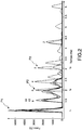
- the FIG 2 is a graph schematically showing an example of signals obtained with the aid of the force sensor 12 during a test for the insertion of a femoral rod 2 into the femur 4 of a cadaver.
- the time (t) in milliseconds (ms) is plotted on the abscissa, the force measured by the sensor 12, in Newtons (N), is plotted on the ordinate.
- each signal corresponds to an impact. In total, during this insertion test, twenty-five impacts were made on the femoral stem 2. However, for the sake of better visibility, only the signals corresponding to the second, third, fourth, fifth, ninth, thirteenth, eighteenth and twenty-fourth impacts are represented on the FIG 2 . We can clearly distinguish for each signal two first peaks of maximum amplitude.
- the first peak of maximum amplitude P1 appears almost instantaneously (ie one millisecond later) at time t1.
- the first peaks P1 of the different signals are superimposed in time on the FIG 2 , the abscissa t1 of the first peak P1 being the same for each impact.
- the amplitude of the first peak P1 reflects the force of impaction exerted during the impact.
- the second peak of maximum amplitude appears a few tenths of a millisecond to a few milliseconds after the first peak P1.
- the second peak appears at time t2.
- the second peak is identified and noted P2 only for the third and fifth impact (or impacts of rank 3 and 5).
- the instant t2 is only marked for the third and the fifth impact.
- the duration (t2 - t1) between the first and second peaks P1, P2 decreases as a function of the rank of the impact and the inventors have demonstrated the fact that this duration (t2 - t1) was a reliable and relevant IN1 indicator to reflect the level of contact between the femoral stem 2 and the femur 4.
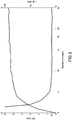
- the FIG 3 is a graph representing the evolution of the IN1 indicator (solid line curve) as a function of the number of impacts and the evolution of the driving-in length L of the rod 2 as a function of the number of impacts during the same insertion test than that of the FIG. 2 .
- the insertion of the rod 2 into the femur 4 was filmed and the length L was measured on the video images (dotted curve).
- the number of impacts (from 1 to 25) is shown on the abscissa.
- the IN1 indicator expressed in milliseconds (ms), is plotted on the ordinate.
- the length of the rod L driven into the femur 4 measured on the video images and expressed in number of pixels is also plotted on the ordinate.
- the driving-in length L increases rapidly and the IN1 indicator decreases rapidly.
- the rod has arrived "at the dock” and hardly sinks in despite the impacts.
- the surface of the rod 2 in contact with the femur 4 is maximum and hardly varies despite the impacts.
- the indicator IN1 also reaches a plateau.
- This graph illustrates the fact that the IN1 indicator is relevant to represent the level of contact between rod 2 and femur 4.
- the value of the indicator IN1 18th impact can be chosen as threshold value S1 for setting the processing unit 30.
- the threshold value S1 was selected equal to 0.32 ms.
- the threshold value S1 is between 0.1 and 1 ms.
- the threshold value S1 can be used to parameterize the insertion device 10.
- This threshold value S1 is, for example, recorded in the memory of the processing unit 30.
- the device 10 can comprise a alert system 33 for emitting an alert signal (for example, an audible, visual and / or tactile signal).
- the alert system 33 is connected to the processing unit 30 and cooperates with the latter to alert the practitioner when the level of contact between the rod 2 and the femur 4 is deemed sufficient on the basis of the indicator IN1, that is to say, in this example, as soon as the indicator IN1 drops below the threshold value S1. Therefore, the practitioner has real-time reliable information indicating that he has reached a sufficient level of stem-femur contact. He concludes that it can stop impacting the stem 2, which decreases the risk of damaging the femur 4, in particular inducing a fracture or microcracks in the femur 4.
- the proposed device can be used for implants for hip prostheses other than a femoral stem (e.g. for acetabular implants), implants for prosthesis of the knee, shoulder, spine, ankle, etc. and, more generally, any type of surgical implant requiring to be inserted by force by impaction into a receiving bone. It can also be used for the insertion of surgical instruments inserted temporarily into a patient's body and, for example, for the insertion of a surgical rasp such as a femoral rasp for hip prosthesis.
- the femoral rasps are intended to be inserted by force by impaction into the medullary canal in order to prepare this canal to receive the femoral stem.
- These rasps are impacted directly by an impactor, with or without the intermediary of a fitting instrument. If no placement ancillary is used, then the impact surface is formed by a surface located at the rear end of a gripping part of the rasp.
- the example which has just been described implements a force sensor 12.
- a deformation sensor capable of supplying a measurement signal representing the variation. temporal of the deformation of the impactor 10 during an impact.
- a deformation sensor is able to convert the deformation of the striking head 11 of the impactor 10 into an exploitable electrical signal.
- the deformation sensor instead of being located on the striking face 11a as the force sensor 12, the deformation sensor is positioned on one of the side faces 11c of the striking head 11. In this case, the deformation sensor is positioned on the side face 11c extending parallel to the direction of the axis of the handle. 13.
- the deformation sensor is fixed on the front part of the lateral face 11c, between the striking face 11a and the axis of the handle 13.
- the front and the rear are defined here with respect to the striking movement of the Impactor 10.
- the deformation sensor is fixed on the striking head 11, for example by gluing or any other suitable fixing means, so that the deformation of the striking head 11 causes the deformation of the sensor.
- the sensor is, for example, a gauge sensor comprising a measuring element elastic whose deformation is first converted into a variation in the electrical resistance of the gauge, to then generate an electrical output signal.
- it may be a piezoelectric sensor based on the piezoelectric properties of a material (eg quartz or synthetic ceramics) which generates an electric charge when it is deformed.
- the measurement signal supplied by such a deformation sensor and representing the temporal variation of the deformation of the impactor during an impact also exhibits first and second peaks of maximum amplitude.
- the time lapse between these two peaks also proves to be a reliable and relevant indicator for evaluating the level of contact between the implant and the receiving bone.
Landscapes
- Health & Medical Sciences (AREA)
- Orthopedic Medicine & Surgery (AREA)
- Life Sciences & Earth Sciences (AREA)
- Transplantation (AREA)
- Engineering & Computer Science (AREA)
- Public Health (AREA)
- Biomedical Technology (AREA)
- Heart & Thoracic Surgery (AREA)
- Surgery (AREA)
- Veterinary Medicine (AREA)
- Animal Behavior & Ethology (AREA)
- General Health & Medical Sciences (AREA)
- Oral & Maxillofacial Surgery (AREA)
- Physical Education & Sports Medicine (AREA)
- Nuclear Medicine, Radiotherapy & Molecular Imaging (AREA)
- Cardiology (AREA)
- Vascular Medicine (AREA)
- Molecular Biology (AREA)
- Medical Informatics (AREA)
- Biophysics (AREA)
- Prostheses (AREA)
- Surgical Instruments (AREA)
Description
- L'invention concerne un dispositif pour insérer un implant chirurgical par impaction dans un os récepteur. Ce dispositif comprend un outil de percussion, ou impacteur, adapté pour exercer une force d'impaction sur l'implant chirurgical afin d'insérer en force celui-ci dans l'os récepteur.
- Dans le présent exposé, la notion d'implant chirurgical ne se limite pas aux implants chirurgicaux proprement dits mais englobe également les instruments chirurgicaux insérés temporairement dans un os récepteur. Cette notion recouvre, en particulier, l'ensemble des implants de prothèse orthopédique destinés à remplacer une articulation déficiente, notamment les implants de prothèses de hanche, de genoux, d'épaule, de rachis, de coude ou de cheville, et les instruments de pose utilisés pour préparer l'os récepteur à recevoir la prothèse.
- L'invention se rapporte plus particulièrement, mais non exclusivement, à la mise en place d'une prothèse de hanche. La grande majorité des prothèses de hanche ont en commun une première partie fixée sur le fémur et une deuxième partie fixée sur le bassin. La première partie comprend une tige fémorale destinée à être insérée en force dans le canal médullaire du fémur et une tête prothétique formée d'une pièce sphérique, montée sur la tige fémorale et se substituant à la tête du fémur. La seconde partie comprend une cotyle prothétique destiné à être inséré dans la cavité cotyloïdienne située sur la face latérale de l'os iliaque du bassin pour remplacer la partie articulaire du bassin. La cotyle prothétique peut comprendre une cupule cotyloïdienne, qui est une pièce approximativement hémisphérique, généralement en métal, insérée dans la cavité cotyloïdienne et dans laquelle se place un insert avec lequel s'articule la tête prothétique.
- L'insertion de la tige fémorale dans le canal médullaire est généralement réalisée par impaction au moyen d'un impacteur, typiquement un marteau. Un ancillaire de pose peut également être utilisé, le praticien utilisant l'impacteur pour frapper l'ancillaire qui transmet la force d'impaction à la tige fémorale.
- Au fur et à mesure des impacts, la tige s'enfonce dans le canal médullaire. La tige s'enfonçant sur une grande partie de sa longueur, le déplacement relatif entre la tige et le fémur est important. Le niveau de contact entre la tige et le fémur qui l'entoure dépend de cet enfoncement. Ce niveau de contact est généralement caractérisé par le ratio BIC (en anglais "BIC ratio" pour "bone to implant contact ratio") qui est le pourcentage de la surface de l'implant au contact de l'os. Plus la tige s'enfonce, plus la surface de la tige au contact du fémur augmente.
- Le praticien souhaite avant tout suivre l'enfoncement de la tige dans le fémur et déterminer le moment où le niveau de contact entre la tige et le fémur est optimal ou, tout au moins, satisfaisant. La réussite de l'opération repose à la fois sur un niveau de contact suffisant entre la tige et le fémur et sur le fait de ne pas endommager et notamment de ne pas induire de fracture ou de microfissures dans le fémur lors de l'insertion. Si la tige fémorale est insuffisamment insérée dans le fémur, il peut s'ensuivre des micromouvements de la tige pouvant nécessiter une nouvelle intervention chirurgicale.
- Un compromis doit donc être trouvé entre un nombre d'impacts suffisamment élevé pour obtenir un niveau de contact satisfaisant entre la tige et le fémur et suffisamment faible pour ne pas risquer d'endommager le fémur. Or, il est difficile pour le praticien d'évaluer par lui-même avec fiabilité le bon nombre d'impacts. Concrètement, il lui est difficile de savoir précisément quand arrêter de frapper la tige fémorale avec l'impacteur.
- Dans ce contexte et, plus généralement, dans le contexte de l'insertion en force d'un implant chirurgical dans un os récepteur par impaction, un but de l'invention est de proposer un dispositif permettant de fournir, durant l'opération chirurgicale, une information fiable sur le niveau de contact entre l'implant et l'os récepteur et de permettre ainsi au praticien de savoir, en temps réel, quand il doit arrêter de frapper l'implant avec l'impacteur.
- Le document de brevet
FR 3019031 - Le document
US2015/282856 A1 décrit un dispositif selon le préambule de la revendication 1. - L'invention concerne un dispositif pour insérer en force un implant chirurgical dans un os récepteur, par impaction. Ce dispositif comprend un impacteur adapté pour impacter une surface d'impact couplée audit implant chirurgical et exercer une force d'impaction sur l'implant.
- L'impacteur est associé à au moins un capteur apte à mesurer une grandeur parmi la force d'impaction exercée et la déformation de l'impacteur, et à fournir un signal de mesure représentant la variation temporelle de ladite grandeur lors d'un impact.
- Le capteur (i.e. ledit au moins un capteur) est relié à une unité de traitement configurée pour déterminer à partir de la variation temporelle de ladite grandeur lors de l'impact, un indicateur représentatif du niveau de contact entre l'implant et l'os récepteur. La liaison électronique entre le capteur et l'unité de traitement peut être filaire ou non.
- La solution proposée repose sur la mise en œuvre d'un ou plusieurs capteurs associés à l'impacteur et délivrant un signal de mesure, l'enregistrement et l'analyse de ce signal permettant de déterminer un indicateur révélateur du niveau de contact entre l'implant et l'os récepteur. Lorsque plusieurs capteurs sont utilisés, les signaux respectivement délivrés par ces capteurs peuvent être, par exemple, moyennés ou combinés pour obtenir le signal de mesure qui sera analysé et à partir duquel l'indicateur sera calculé.
- Un tel dispositif permet, au cours de l'opération d'insertion de l'implant chirurgical, de renseigner en temps réel le praticien sur le niveau de contact atteint entre l'implant et l'os récepteur. Outre son coût réduit, ce dispositif a l'avantage d'être simple d'utilisation. En particulier, avec ce dispositif, le geste du praticien lors de l'opération reste le même. Le praticien n'a donc pas à apprendre de nouveaux gestes et peut tirer profit de l'expérience qu'il a déjà acquise avec les dispositifs conventionnels.
- L'indicateur proposé correspond à la durée d'une fenêtre temporelle, le début de cette fenêtre temporelle étant défini par rapport à un instant correspondant au premier pic d'amplitude maximale du signal de mesure et la fin de cette fenêtre temporelle étant définie par rapport à un instant correspondant au deuxième pic d'amplitude maximale du signal de mesure. Il a été montré que l'indicateur ainsi calculé était corrélé au niveau de contact entre l'implant et l'os récepteur et constituait un indicateur fiable.
- Dans certains modes de réalisation le dispositif comprend, en outre, un système d'alerte relié à l'unité de traitement et coopérant avec celle-ci de manière à émettre un signal d'alerte lorsque l'indicateur devient inférieur à (i.e. descend en dessous de) une valeur seuil prédéterminée. Cette valeur seuil peut être déterminée expérimentalement. Par exemple, on réalise des tests et on choisit comme valeur seuil la valeur de l'indicateur à partir de laquelle on constate un niveau de contact suffisant entre l'implant et l'os récepteur. En particulier, la valeur seuil peut être comprise entre 0,1 et 1 ms.
- Ainsi, le fait que la durée de ladite fenêtre temporelle devienne inférieure à une certaine durée, prédéterminée, est utilisé comme condition pour émettre le signal d'alerte (e.g. une lumière, un son, une vibration, etc.). Le praticien, averti par ce signal, sait alors qu'il doit arrêter d'impacter l'implant, le niveau de contact entre l'implant et l'os étant considéré comme optimal ou, en tous cas, comme suffisant.
- Bien entendu, d'autres conditions relatives à l'indicateur lui-même ou à la variation de l'indicateur lors d'une série d'impacts successifs pourraient être utilisées pour déclencher une alerte, sans sortir du cadre de l'invention. En particulier, il est possible de tirer profit du fait que, lorsqu'un niveau de contact os-implant satisfaisant est atteint, l'indicateur proposé tend à se stabiliser (i.e. converge vers une valeur stationnaire).
- Dans certains modes de réalisation, l'unité de traitement détecte dans le signal de mesure le premier pic d'amplitude maximale et le pic d'amplitude maximale succédant au premier pic, ce dernier pic n'étant considéré comme le deuxième pic d'amplitude maximale que si le signal de mesure devient inférieur à une valeur limite prédéterminée entre ces deux pics (i.e. si le signal de mesure descend au-dessous de la valeur limite avant de repasser au-dessus de cette valeur pour former le deuxième pic). En particulier, la valeur limite peut être comprise entre 1 à 20% de l'amplitude maximale du premier pic. Par exemple, le pic d'amplitude maximale succédant au premier pic n'est considéré comme le deuxième pic d'amplitude maximale que si le signal de mesure passe au-dessous d'une valeur limite égale à 5% de l'amplitude maximale du premier pic.
- Cette précaution permet d'éviter les erreurs de mesure liées à un phénomène de dédoublement du premier pic, qui a pu être observé dans un petit nombre de cas. Lors d'un tel phénomène, les deux pics obtenus par dédoublement du premier pic sont proches l'un de l'autre et les inventeurs ont réalisé que le signal de mesure n'avait pas le temps de diminuer significativement entre ces deux pics. Aussi, la solution consistant à vérifier que le signal de mesure a suffisamment diminué avant d'atteindre le deuxième pic d'amplitude maximale, permet d'éviter de considérer à tort le doublon du premier pic comme le deuxième pic d'amplitude maximale, et donc d'éviter une erreur de mesure sur l'indicateur. Bien entendu, d'autres méthodes d'analyse du signal de mesure pourraient être envisagées pour détecter un dédoublement du premier pic et éviter des erreurs de mesure dans un tel cas.
- Dans certains modes de réalisation, l'impacteur a une face de frappe adaptée pour impacter la surface d'impact et le capteur est un capteur de force apte à mesurer la force d'impaction et à fournir un signal de mesure représentant la variation temporelle de la force d'impaction lors d'un impact.
- Dans d'autres modes de réalisation, l'impacteur a une face de frappe adaptée pour impacter la surface d'impact, une face opposée à la face de frappe et des faces latérales s'étendant entre la face de frappe et la face opposée, et le capteur est un capteur de déformation apte à mesurer la déformation de l'impacteur et à fournir un signal de mesure représentant la variation temporelle de la déformation de l'impacteur lors d'un impact.
- Dans certains modes de réalisation, l'impacteur est un marteau, ou équivalent, et comprend un manche surmonté d'une tête de frappe. En particulier, l'impacteur peut avoir sensiblement la même forme et le même poids que les impacteurs couramment utilisés jusqu'à présent. Ainsi, les praticiens expérimentés sont immédiatement en mesure de manier correctement l'impacteur.
- On notera que la surface d'impact peut-être couplée directement à l'implant en ce sens qu'il peut s'agir d'une des surfaces de l'implant, ou peut être indirectement couplée à l'implant en ce sens qu'il peut s'agir d'une surface d'un instrument, ou ancillaire de pose, venant lui-même au contact de l'implant. Dans ce dernier cas, l'impacteur exerce la force d'impaction sur l'implant par l'intermédiaire de l'ancillaire de pose. En d'autres termes, la force d'impaction est exercée sur l'ancillaire de pose et transmise par celui-ci à l'implant.
- Dans certains modes de réalisation, le dispositif comprend un ancillaire de pose ayant une extrémité arrière formant ladite surface d'impact et une extrémité avant adaptée pour coopérer avec l'implant, l'impacteur exerçant la force d'impaction sur l'implant par l'intermédiaire de l'ancillaire de pose.
- L'extrémité avant de l'ancillaire de pose peut coopérer avec l'implant par simple contact. En variante, l'extrémité avant de l'ancillaire de pose peut être attachée mécaniquement à l'implant orthopédique de manière amovible, par exemple par vissage. Le fait d'attacher l'ancillaire à l'implant permet, généralement, d'obtenir un meilleur signal de mesure. L'ancillaire est amovible de manière à pouvoir détacher facilement l'ancillaire de l'implant une fois ce dernier en position.
- Le présent exposé concerne également un ensemble comprenant un dispositif tel que précédemment décrit et un implant chirurgical, en particulier une tige fémorale.
- La présente description décrit également un procédé n'appartenant pas à l'invention pour insérer en force un implant chirurgical dans un os récepteur, par impaction, dans lequel:
- on fournit un dispositif tel que précédemment décrit,
- on exerce avec l'impacteur une force d'impaction sur l'implant, en impactant une surface d'impact couplée à l'implant, de manière à insérer l'implant,
- on calcule l'indicateur lors d'impacts successifs, et
- on arrête d'impacter la surface d'impact lorsque l'indicateur devient inférieur à une valeur seuil prédéterminée.
- L'implant chirurgical peut être, mais n'est pas nécessairement, une tige fémorale. Dans ce cas, on impacte la tige fémorale avec l'impacteur de manière à insérer en force la tige dans le canal médullaire du fémur d'un patient.
- Les avantages d'un tel procédé découlent des avantages du dispositif utilisé.
- Les caractéristiques et avantages précités, ainsi que d'autres, apparaîtront à la lecture de la description détaillée qui suit, d'exemples de réalisation du dispositif proposé. Cette description détaillée fait référence aux dessins annexés.
- Les dessins annexés sont schématiques et ne sont pas à l'échelle, ils visent avant tout à illustrer les principes de l'invention.
- la
figure 1 est une représentation schématique d'un dispositif pour insérer un implant chirurgical, comprenant un impacteur muni d'un capteur de force. - la
figure 2 représente schématiquement un exemple de signaux obtenus à l'aide du capteur de force de lafigure 1 , lors de l'insertion de l'implant. - la
figure 3 représente schématiquement la variation de l'indicateur retenu et la variation de l'enfoncement de l'implant en fonction du nombre d'impacts. - La figure (
FIG) 1 représente un exemple de dispositif 1 pour insérer progressivement un implant chirurgical dans un os récepteur, par impaction. Dans cet exemple, l'implant est un implant pour prothèse, en particulier une tige fémorale 2 pour prothèse de hanche. Cette tige 2 est destinée à être insérée progressivement par impaction dans le canal médullaire 3 du fémur 4 d'un patient. Le canal médullaire 3 est, généralement, préalablement préparé par le praticien pour recevoir la tige 2. Dans tous les cas, les dimensions de la tige 2 sont légèrement supérieures aux dimensions du canal médullaire 3 et la tige 2 est insérée en force dans ce canal. - La tige fémorale 2 comprend un col prothétique 7 destiné à dépasser du fémur 4 et dont l'extrémité 7a reçoit une sphère (non représentée), et un corps 8 effilé s'étendant à partir du col 7 et dont la section transversale diminue à mesure que l'on s'éloigne du col 7. Le corps 8 est destiné à être enfoncé intégralement dans le fémur 4. Sur la
FIG 1 , le corps 8 est représenté partiellement enfoncé dans le fémur 4. Le col 7 présente également, à côté de son extrémité 7a, une surface d'appui 7b pour un ancillaire de pose 20. - Dans cet exemple, l'ancillaire de pose 20 est une barre ayant une extrémité arrière formant une surface d'impact 20a et une extrémité avant 20b adaptée pour venir au contact de la surface d'appui 7b de la tige 2. L'extrémité avant 20b de l'ancillaire 20 peut coopérer avec la tige 2 par simple contact avec la surface d'appui 7b ou être attachée mécaniquement à la tige de manière amovible, par exemple par vissage. Dans ce dernier cas, l'extrémité avant 20b de l'ancillaire 20 peut être filetée pour être vissée dans un trou taraudé (non représenté) ménagé dans la surface de contact 7b. L'avant et l'arrière sont définis ici par rapport à la direction d'avancement de la tige 2 et de l'ancillaire 20 lors de l'impaction.
- Le dispositif 1 comprend également un outil de percussion ou impacteur 10, de type marteau ou équivalent, comprenant un manche 13 surmonté d'une tête de frappe 11. La tête de frappe 11 a une face de frappe 11a adaptée pour impacter la surface d'impact 20a de l'ancillaire 20, une face 11b opposée à la face de frappe 11a et des faces latérales 11c s'étendant entre la face de frappe 11a et la face opposée 11b. Lorsqu'il souhaite enfoncer la tige fémorale 2 dans le fémur 4, le praticien saisit l'ancillaire de pose 20 d'une main et le manche 13 de l'impacteur 10 de l'autre main. Il frappe ensuite la surface d'impact 20a de l'ancillaire 20 avec la face de frappe 11a de l'impacteur. La force d'impaction générée par l'impacteur 10 est transmise à la tige fémorale 2 par l'intermédiaire de l'ancillaire 20.
- Dans l'exemple de la
FIG 1 , l'impacteur 10 est équipé d'un capteur de force 12 apte à mesurer la force d'impaction exercée sur l'implant par l'impacteur 10 et à fournir un signal de mesure représentant la variation temporelle de la force d'impaction lors d'un impact. Un exemple de capteur de force de ce type est décrit dans le document de brevetFR 3019031 FIG 1 , un tel capteur de force 12 est apte à convertir en un signal électrique exploitable la force d'impaction appliquée sur la surface d'impact 20a de l'ancillaire de pose 20 lors de chaque frappe. Il s'agit, par exemple, d'un capteur à jauge ou d'un capteur piézo-électrique connecté selon un montage approprié à l'unité de traitement 30. Dans l'exemple représenté, le capteur de force 12 est fixée sur la face de frappe 11a de la tête 11 de l'impacteur 10. En variante, le capteur de force 12 peut être positionné au niveau de la surface d'impact 20a de l'ancillaire de pose 20, voir au niveau de l'interface entre l'ancillaire de pose 20 et la tige fémorale. Dans les applications n'utilisant pas d'ancillaire, le capteur de force 12 peut être positionné au niveau de la surface de l'implant 2 qui forme la surface d'impact. - Le dispositif comprend également une unité de traitement 30 couplée au capteur 12 et configurée pour quantifier le contact entre la tige 2 et l'os récepteur, i.e. le fémur 4, à partir des signaux de mesure délivrés par le capteur 12. Cette unité de traitement 30 comprend, par exemple, un microcontrôleur 34. L'unité de traitement 30 peut être logée dans un boîtier externe 32. En variante, l'unité de traitement 30 peut être intégrée à l'impacteur 10. Selon une autre variante, l'unité de traitement 30 peut être formée d'éléments séparés comme un micro-ordinateur relié à un module d'acquisition de données lui-même relié au capteur 12.
- La liaison entre le capteur 12 et l'unité de traitement 30 est, dans l'exemple de la
FIG 1 , réalisée de manière filaire au moyen d'un câble 15. En variante, la transmission des signaux de mesure fournis par le capteur 12 peut se faire au moyen d'une liaison sans fil, auquel cas le capteur 12 est équipé d'une antenne ou équivalent. - Lors de chaque impact effectué par le praticien sur la tige 2 au moyen de l'impacteur 10, via l'ancillaire de pose 20, le capteur 12 mesure la force d'impaction exercée et fournit un signal de mesure représentant la variation temporelle de cette force pendant l'impact. On considère que l'impact commence à partir de l'instant où l'impacteur 10 et l'implant entrent en contact, directement ou indirectement (i.e. via l'ancillaire 20), et dure pendant un certain laps de temps après cet instant. En tout état de cause, ce laps de temps est inférieur à 50 ms. Des exemples de signaux fournis par le capteur 12 sont représentés sur la
FIG. 2 et décrits ci-après. - Les inventeurs ont eu l'idée de s'intéresser à un tel signal de mesure et ont mis en évidence le fait que ce signal portait des informations sur le niveau de contact entre le fémur 4 et la tige 2. En particulier, les inventeurs ont réussi à déterminer, à partir du signal de mesure recueilli, un indicateur représentatif du niveau de contact entre le fémur 4 et la tige 2, comme expliqué ci-après.
- Pour essayer d'expliquer le lien entre le signal de mesure recueilli et le niveau de contact tige-fémur, l'explication suivante peut être avancée. L'impacteur 10 exerce sur la tige 2, via l'ancillaire 20, une force d'impaction qui est à l'origine de modes de vibration dans l'ensemble du système formé par l'impacteur 10, le capteur 12, l'ancillaire 20, la tige fémorale 2 et le fémur 4 lorsque ces éléments sont tous en contact lors de l'impact. Ces modes de vibration dépendent essentiellement des modes de vibration du système os-implant (i.e. du système fémur-tige) qui dépendent à leur tour du niveau de contact entre l'implant et l'os. Schématiquement, plus le niveau de contact os-implant est élevé, plus le système os-implant est rigide et plus les fréquences de résonnance des modes de vibration sont élevées.
- La
FIG 2 est un graphique représentant schématiquement un exemple de signaux obtenus à l'aide du capteur de force 12 lors d'un test d'insertion d'une tige fémorale 2 dans le fémur 4 d'un cadavre. Le temps (t) en millisecondes (ms) est reporté en abscisse, la force mesurée par le capteur 12, en Newtons (N), est reportée en ordonnée. - Plusieurs signaux sont représentés sur la
FIG 2 . Chaque signal correspond à un impact. Au total, lors de ce test d'insertion, vingt cinq impacts ont été portés sur la tige fémorale 2. Toutefois, dans un souci de meilleure visibilité, seuls les signaux correspondants aux deuxième, troisième, quatrième, cinquième, neuvième, treizième, dix-huitième et vingt quatrième impacts sont représentés sur laFIG 2 . On distingue clairement pour chaque signal deux premiers pics d'amplitude maximale. - Chaque impact est porté au temps t = 0. Le premier pic d'amplitude maximale P1 apparaît quasi-instantanément (i.e. une milliseconde après) au temps t1. Les premiers pics P1 des différents signaux sont superposés en temps sur la
FIG 2 , l'abscisse t1 du premier pic P1 étant la même pour chaque impact. L'amplitude du premier pic P1 reflète la force d'impaction exercée lors de l'impact. - Le deuxième pic d'amplitude maximale apparaît quelques dixièmes de milliseconde à quelques millisecondes après le premier pic P1. Comme indiqué précédemment, seuls les signaux correspondants aux impacts de rang 2, 3, 4, 5, 9, 13, 18 et 24 sont représentés sur la
FIG 2 . Ces rangs sont indiqués au dessus des deuxièmes pics d'amplitude maximale des signaux correspondants. Le deuxième pic apparaît à l'instant t2. Sur laFIG 2 , le deuxième pic est repéré et noté P2 uniquement pour le troisième et le cinquième impact (ou impacts de rang 3 et 5). De même, l'instant t2 n'est repéré que pour le troisième et le cinquième impact. - Comme illustré par la
FIG 2 , la durée (t2 - t1) entre les premier et deuxième pics P1, P2 diminue en fonction du rang de l'impact et les inventeurs ont mis en évidence le fait que cette durée (t2 - t1) était un indicateur IN1 fiable et pertinent pour refléter le niveau de contact entre la tige fémorale 2 et le fémur 4. - La
FIG 3 est un graphique représentant l'évolution de l'indicateur IN1 (courbe en trait plein) en fonction du nombre d'impacts et l'évolution de la longueur d'enfoncement L de la tige 2 en fonction du nombre d'impacts lors du même test d'insertion que celui de laFIG. 2 . L'insertion de la tige 2 dans le fémur 4 a été filmée et la longueur L a été mesurée sur les images vidéo (courbe en pointillés). Le nombre d'impacts (de 1 à 25) est reporté en abscisse. L'indicateur IN1, exprimé en millisecondes (ms), est reporté en ordonnée. La longueur de tige L enfoncée dans le fémur 4, mesurée sur les images vidéo et exprimée en nombre de pixels est également reportée en ordonnée. - Comme illustré par la
FIG 3 , de manière générale, plus la longueur d'enfoncement L de la tige fémorale 2 dans le fémur augmente, et donc plus la surface de la tige 2 au contact du fémur 4 augmente, plus l'indicateur IN1 diminue. Dans un premier temps, la longueur d'enfoncement L augmente rapidement et l'indicateur IN1 diminue rapidement. Ensuite, au bout d'un certain nombre d'impacts, la tige est arrivée "à quai" et ne s'enfonce pratiquement plus malgré les impacts. Ceci se traduit sur laFIG 3 par un palier dans l'évolution de la longueur d'enfoncement L. A ce moment, la surface de la tige 2 au contact du fémur 4 est maximum et ne varie pratiquement plus malgré les impacts. On constate qu'au même moment l'indicateur IN1 atteint lui aussi un palier. Ce graphique illustre le fait que l'indicateur IN1 est pertinent pour représenter le niveau de contact entre la tige 2 et le fémur 4. - En outre, dans ce test d'insertion, il a été considéré (notamment sur la base des images vidéo réalisées) que le niveau de contact tige-fémur était optimal ou, en tous cas, suffisant à partir du 18ème impact. Sur cette base, la valeur de l'indicateur IN1 au 18ème impact peut être choisie comme valeur seuil S1 pour paramétrer l'unité de traitement 30. Dans cet exemple, la valeur seuil S1 a été choisie égale à 0,32 ms. Bien entendu, il ne s'agit là que d'un exemple, et d'autres tests pourraient être réalisés, en alternative ou en combinaison, pour déterminer la valeur seuil S1 correspondant à un niveau de contact tige-fémur jugé suffisant. Typiquement, la valeur seuil S1 est comprise entre 0,1 et 1 ms.
- Une fois déterminée, la valeur seuil S1 peut être utilisée pour paramétrer le dispositif d'insertion 10. Cette valeur seuil S1 est, par exemple, enregistrée dans la mémoire de l'unité de traitement 30. En outre, le dispositif 10 peut comprendre un système d'alerte 33 pour émettre un signal d'alerte (par exemple, un signal sonore, visuel et/ou tactile). Le système d'alerte 33 est relié à l'unité de traitement 30 et coopère avec celle-ci pour alerter le praticien lorsque le niveau de contact entre la tige 2 et le fémur 4 est jugé suffisant sur la base de l'indicateur IN1, c'est-à-dire, dans cet exemple, dès que l'indicateur IN1 descend en dessous de la valeur seuil S1. Dès lors, le praticien dispose en temps réel d'une information fiable lui indiquant qu'il a atteint un niveau de contact tige-fémur suffisant. Il en conclut qu'il peut arrêter d'impacter la tige 2, ce qui diminue le risque d'endommager le fémur 4, en particulier d'induire une fracture ou des microfissures dans le fémur 4.
- L'exemple qui vient d'être décrit, concernant l'insertion d'une tige fémorale dans un fémur, est donné à titre illustratif et non limitatif, une personne du métier pouvant facilement tirer profit de l'indicateur proposé par les inventeurs avec d'autres types d'implants, sans sortir du cadre de l'invention. Autrement dit, la tige 2 et le fémur 4 ne sont, respectivement, que des exemples d'implant chirurgical et d'os récepteur au sens de l'invention.
- En particulier, le dispositif proposé peut être utilisé pour des implants pour prothèse de hanche autres qu'une tige fémorale (e.g. pour des implants cotyloïdiens), des implants pour prothèse de genou, d'épaule, de rachis, de cheville, etc. et, plus généralement, tout type d'implant chirurgical nécessitant d'être inséré en force par impaction dans un os récepteur. Il peut également être utilisé pour l'insertion d'instruments chirurgicaux insérés temporairement dans le corps d'un patient et, par exemple, pour l'insertion d'une râpe chirurgicale comme une râpe fémorale pour prothèse de hanche. Les râpes fémorales sont prévues pour être insérées en force par impaction dans le canal médullaire afin de préparer ce canal à recevoir la tige fémorale. Ces râpes sont impactées directement par un impacteur, avec ou sans l'intermédiaire d'un ancillaire de pose. Si aucun ancillaire de pose n'est utilisé, la surface d'impact est alors constituée par une surface située au niveau de l'extrémité arrière d'une partie de préhension de la râpe.
- En outre, l'exemple qui vient d'être décrit met en œuvre un capteur de force 12. Selon un autre exemple (non représenté), il est possible d'utiliser un capteur de déformation apte à fournir un signal de mesure représentant la variation temporelle de la déformation de l'impacteur 10 lors d'un impact. Dans une situation d'insertion d'une tige fémorale 2 comme celle représentée sur la
FIG 1 , un tel capteur de déformation est apte à convertir en un signal électrique exploitable la déformation de la tête de frappe 11 de l'impacteur 10. Dans ce cas, au lieu d'être situé sur la face de frappe 11a comme le capteur de force 12, le capteur de déformation est positionné sur une des faces latérales 11c de la tête de frappe 11. En l'occurrence, le capteur de déformation est positionné sur la face latérale 11c s'étendant parallèlement à la direction de l'axe du manche 13. Plus précisément, vu de côté (comme sur laFIG 1 ), le capteur de déformation est fixé sur la partie avant de la face latérale 11c, entre la face de frappe 11a et l'axe du manche 13. L'avant et l'arrière sont définis ici par rapport au mouvement de frappe de l'impacteur 10. Le capteur de déformation est fixé sur la tête de frappe 11, par exemple par collage ou tout autre moyen de fixation approprié, de sorte que la déformation de la tête de frappe 11 provoque la déformation du capteur. Le capteur est, par exemple, un capteur à jauge comprenant un élément de mesure élastique dont la déformation est d'abord convertie en une variation de résistance électrique de la jauge, pour générer ensuite un signal de sortie électrique. En variante, il peut s'agir d'un capteur piézo-électrique reposant sur les propriétés piézo-électriques d'un matériau (e.g. du quartz ou des céramiques synthétiques) qui génère une charge électrique lorsqu'il se déforme. - Le signal de mesure fourni par un tel capteur de déformation et représentant la variation temporelle de la déformation de l'impacteur lors d'un impact présente également des premier et deuxième pics d'amplitude maximale. Le laps de temps séparant ces deux pics s'avère également être un indicateur fiable et pertinent pour évaluer le niveau de contact entre l'implant et l'os récepteur.
- Enfin, les différentes caractéristiques des modes ou exemples de réalisation décrits dans le présent exposé peuvent être considérées isolément ou être combinées entre elles. Lorsqu'elles sont combinées, ces caractéristiques peuvent l'être comme décrit ci-dessus ou différemment, l'invention ne se limitant pas aux combinaisons spécifiques précédemment décrites. En particulier, sauf précision contraire ou incompatibilité technique, une caractéristique décrite en relation avec un mode ou exemple de réalisation peut être appliquée de manière analogue à un autre mode ou exemple de réalisation.
Claims (11)
- Dispositif pour insérer en force un implant chirurgical dans un os récepteur, par impaction, comprenant:un impacteur (10) adapté pour impacter une surface d'impact (20a) couplée à l'implant et exercer une force d'impaction sur l'implant,au moins un capteur (12) associé à l'impacteur (10), et une unité de traitement (30) reliée au capteur (12),le capteur (12) étant apte à mesurer une grandeur parmi la force d'impaction exercée et la déformation de l'impacteur (10), et à fournir un signal de mesure représentant la variation temporelle de ladite grandeur lors d'un impact,l'unité de traitement (30) étant configurée pour calculer, à partir de la variation temporelle de ladite grandeur lors de l'impact, un indicateur (IN1) représentatif du niveau de contact entre l'implant et l'os récepteur, caractérisé en ce quel'indicateur (IN1) correspond à la durée d'une fenêtre temporelle, le début de cette fenêtre temporelle étant défini par rapport à un instant (t1) correspondant au premier pic (P1) d'amplitude maximale du signal de mesure et la fin de cette fenêtre temporelle étant définie par rapport à un instant (t2) correspondant au deuxième pic d'amplitude maximale (P2) du signal de mesure.
- Dispositif selon la revendication 1 comprenant, en outre, un système d'alerte (33) relié à l'unité de traitement (30) et coopérant avec celle-ci de manière à émettre un signal d'alerte lorsque l'indicateur (IN1) devient inférieur à une valeur seuil (S1) prédéterminée.
- Dispositif selon la revendication 2, dans lequel la valeur seuil (S1) prédéterminée est comprise entre 0,1 et 1 ms.
- Dispositif selon l'une quelconque des revendications 1 à 3, dans lequel l'unité de traitement (30) est configurée pour détecter dans le signal de mesure le premier pic (P1) d'amplitude maximale et le pic d'amplitude maximale succédant au premier pic (P1), ce dernier pic n'étant considéré comme le deuxième pic d'amplitude maximale (P2) que si l'amplitude du signal devient inférieure à une valeur limite prédéterminée entre les deux pics.
- Dispositif selon la revendication 4, dans lequel la valeur limite prédéterminée est comprise entre 1 et 20 % de l'amplitude maximale du premier pic (P1).
- Dispositif selon l'une quelconque des revendications 1 à 5, dans lequel l'impacteur (10) a une face de frappe (11a) adaptée pour impacter la surface d'impact (20a), une face opposée (11b) à la face de frappe et des faces latérales (11c) s'étendant entre la face de frappe (11a) et la face opposée (11b), et dans lequel le capteur est un capteur de déformation (12) apte à mesurer la déformation de l'impacteur (10) et à fournir un signal de mesure représentant la variation temporelle de la déformation de l'impacteur (10) lors d'un impact.
- Dispositif selon l'une quelconque des revendications 1 à 6, dans lequel l'impacteur (10) a une face de frappe (11a) adaptée pour impacter la surface d'impact (20a) et dans lequel le capteur est un capteur de force apte à mesurer la force d'impaction et à fournir un signal de mesure représentant la variation temporelle de la force d'impaction lors d'un impact.
- Dispositif selon l'une quelconque des revendications 1 à 7, dans lequel l'impacteur (10) est un marteau, ou équivalent, et comprend un manche (13) surmonté d'une tête de frappe (11).
- Dispositif selon l'une quelconque des revendications 1 à 8, comprenant, en outre, un ancillaire de pose (20) ayant une extrémité arrière formant ladite surface d'impact (20a) et une extrémité avant (20b) adaptée pour coopérer avec l'implant, l'impacteur (10) exerçant la force d'impaction sur l'implant par l'intermédiaire de l'ancillaire de pose (20).
- Ensemble comprenant un dispositif selon l'une quelconque des revendications 1 à 9 et un implant chirurgical, en particulier une tige fémorale (2).
- Ensemble selon la revendication 10 comprenant un dispositif selon la revendication 9, dans lequel l'extrémité avant (20b) de l'ancillaire de pose est attachée mécaniquement à l'implant de manière amovible, par exemple par vissage.
Applications Claiming Priority (2)
| Application Number | Priority Date | Filing Date | Title |
|---|---|---|---|
| FR1759130A FR3071718B1 (fr) | 2017-09-29 | 2017-09-29 | Dispositif d'insertion d'un implant chirurgical |
| PCT/EP2018/076228 WO2019063675A1 (fr) | 2017-09-29 | 2018-09-27 | Dispositif d'insertion d'un implant chirurgical |
Publications (2)
| Publication Number | Publication Date |
|---|---|
| EP3687459A1 EP3687459A1 (fr) | 2020-08-05 |
| EP3687459B1 true EP3687459B1 (fr) | 2021-08-04 |
Family
ID=60515613
Family Applications (1)
| Application Number | Title | Priority Date | Filing Date |
|---|---|---|---|
| EP18785855.0A Active EP3687459B1 (fr) | 2017-09-29 | 2018-09-27 | Dispositif d'insertion d'un implant chirurgical |
Country Status (10)
| Country | Link |
|---|---|
| US (1) | US11490943B2 (fr) |
| EP (1) | EP3687459B1 (fr) |
| JP (1) | JP7240404B2 (fr) |
| KR (1) | KR102583393B1 (fr) |
| CN (1) | CN111417365B (fr) |
| AU (1) | AU2018343867B2 (fr) |
| BR (1) | BR112020006062B1 (fr) |
| CA (1) | CA3082820A1 (fr) |
| FR (1) | FR3071718B1 (fr) |
| WO (1) | WO2019063675A1 (fr) |
Cited By (1)
| Publication number | Priority date | Publication date | Assignee | Title |
|---|---|---|---|---|
| FR3140750A1 (fr) * | 2022-10-14 | 2024-04-19 | Centre National De La Recherche Scientifique | Dispositif de caractérisation de tissus mous biologiques |
Families Citing this family (14)
| Publication number | Priority date | Publication date | Assignee | Title |
|---|---|---|---|---|
| FR3071719B1 (fr) * | 2017-09-29 | 2022-06-03 | Centre Nat Rech Scient | Dispositif d'insertion d'un implant chirurgical |
| FR3071718B1 (fr) * | 2017-09-29 | 2021-11-05 | Centre Nat Rech Scient | Dispositif d'insertion d'un implant chirurgical |
| JP7599016B2 (ja) | 2020-11-10 | 2024-12-12 | ジンマー,インコーポレイティド | 二重スプリング式手術用衝撃工具 |
| US12178663B2 (en) | 2020-12-17 | 2024-12-31 | Mazor Robotics Ltd. | Systems, devices, and methods for monitoring a rod reduction process |
| EP4280984A1 (fr) | 2021-01-21 | 2023-11-29 | Zimmer, Inc. | Outil à impact à marteau chirurgical électrique linéaire |
| AU2022212126B2 (en) * | 2021-01-29 | 2024-07-25 | Zimmer, Inc. | Orthopedic impactor tool |
| JP7680548B2 (ja) | 2021-02-01 | 2025-05-20 | ジンマー,インコーポレイティド | 外科用電動トライロールスレッドインパクトツール |
| AU2022227599B2 (en) | 2021-02-26 | 2024-07-25 | Zimmer, Inc. | Bi-spring surgical hammer impact tools |
| US11423697B1 (en) | 2021-08-12 | 2022-08-23 | Sdc U.S. Smilepay Spv | Machine learning architecture for imaging protocol detector |
| JP7732664B2 (ja) * | 2021-11-16 | 2025-09-02 | 学校法人順天堂 | 術後インプラント沈下量の予測方法 |
| CN114795601B (zh) * | 2022-06-29 | 2022-09-02 | 深圳市迈捷生命科学有限公司 | 一种用于骨科假体固定的植入结构 |
| US12390259B2 (en) | 2022-07-19 | 2025-08-19 | Zimmer, Inc. | Linear electric surgical hammer impact tool |
| US12533171B2 (en) | 2023-03-06 | 2026-01-27 | Zimmer, Inc. | Chuck system for a powered surgical impactor |
| US20250387239A1 (en) * | 2024-06-25 | 2025-12-25 | Orthoiq, Llc | Force sensing devices and methods for orthopedic surgery |
Family Cites Families (22)
| Publication number | Priority date | Publication date | Assignee | Title |
|---|---|---|---|---|
| EP0351430B1 (fr) * | 1986-08-28 | 1994-05-04 | Mitsui Engineering and Shipbuilding Co, Ltd. | Appareil d'inspection de structures du type a impact |
| US20070149981A1 (en) * | 2005-12-09 | 2007-06-28 | Massachusetts General Hospital | Implant insertion device |
| WO2015109203A2 (fr) * | 2014-01-16 | 2015-07-23 | Archer Sciences, LLC | Dispositifs de concassage et de retrait |
| FR3019031B1 (fr) * | 2014-03-27 | 2016-04-15 | Centre Nat De La Rech Scient (Cnrs) | Dispositif d'assistance a la mise en place d'un instrument orthopedique |
| US10426541B2 (en) * | 2014-04-02 | 2019-10-01 | Centre National De La Recherche Scientifique (Cnrs) | Device for assisting with the placement of an orthopedic instrument |
| US10070972B2 (en) * | 2014-10-03 | 2018-09-11 | Hospital For Special Surgery | System and method for intraoperative joint contact mechanics measurement |
| US20190350726A1 (en) * | 2016-01-11 | 2019-11-21 | Kambiz Behzadi | Bone preparation apparatus and method |
| US10849766B2 (en) * | 2016-01-11 | 2020-12-01 | Kambiz Behzadi | Implant evaluation in prosthesis installation |
| US10441244B2 (en) * | 2016-01-11 | 2019-10-15 | Kambiz Behzadi | Invasive sense measurement in prosthesis installation |
| US11234840B2 (en) * | 2016-01-11 | 2022-02-01 | Kambiz Behzadi | Bone preparation apparatus and method |
| US10426540B2 (en) * | 2016-01-11 | 2019-10-01 | Kambiz Behzadi | Prosthesis installation |
| US11026809B2 (en) * | 2016-01-11 | 2021-06-08 | Kambiz Behzadi | Prosthesis installation and assembly |
| US20170196707A1 (en) * | 2016-01-11 | 2017-07-13 | Kambiz Behzadi | Surgical impaction centering apparatus and method |
| IL294630B2 (en) * | 2016-03-23 | 2023-12-01 | Canary Medical Inc | Implantable reporting processor for an alert implant |
| EP3534806A1 (fr) * | 2016-11-02 | 2019-09-11 | Zimmer, Inc. | Système d'affichage à rétroaction de force d'impact |
| FR3071719B1 (fr) * | 2017-09-29 | 2022-06-03 | Centre Nat Rech Scient | Dispositif d'insertion d'un implant chirurgical |
| FR3071718B1 (fr) * | 2017-09-29 | 2021-11-05 | Centre Nat Rech Scient | Dispositif d'insertion d'un implant chirurgical |
| EP3714448B1 (fr) * | 2017-11-21 | 2023-12-20 | Cedarome Canada Inc. | Mécanisme d'impacteur pour système de simulation de chirurgie en réalité virtuelle et téléchirurgie |
| GB201800701D0 (en) * | 2018-01-16 | 2018-02-28 | Depuy Ireland Ultd Co | Surgical Impaction apparatus and method |
| FR3084464B1 (fr) * | 2018-07-26 | 2021-02-26 | Centre Nat Rech Scient | Dispositif pour evaluer la solidite d'un materiau |
| US11596528B2 (en) * | 2019-11-15 | 2023-03-07 | DePuy Synthes Products, Inc. | Technologies for determining seating of an orthopaedic implant during an orthopaedic surgical procedure |
| US11426243B2 (en) * | 2020-02-12 | 2022-08-30 | DePuy Synthes Products, Inc. | Technologies for monitoring and predicting impaction state of an orthopaedic surgical implement during an orthopaedic surgical procedure |
-
2017
- 2017-09-29 FR FR1759130A patent/FR3071718B1/fr active Active
-
2018
- 2018-09-27 CA CA3082820A patent/CA3082820A1/fr active Pending
- 2018-09-27 KR KR1020207008988A patent/KR102583393B1/ko active Active
- 2018-09-27 US US16/651,697 patent/US11490943B2/en active Active
- 2018-09-27 WO PCT/EP2018/076228 patent/WO2019063675A1/fr not_active Ceased
- 2018-09-27 JP JP2020539136A patent/JP7240404B2/ja active Active
- 2018-09-27 BR BR112020006062-3A patent/BR112020006062B1/pt active IP Right Grant
- 2018-09-27 AU AU2018343867A patent/AU2018343867B2/en active Active
- 2018-09-27 CN CN201880063762.2A patent/CN111417365B/zh active Active
- 2018-09-27 EP EP18785855.0A patent/EP3687459B1/fr active Active
Cited By (1)
| Publication number | Priority date | Publication date | Assignee | Title |
|---|---|---|---|---|
| FR3140750A1 (fr) * | 2022-10-14 | 2024-04-19 | Centre National De La Recherche Scientifique | Dispositif de caractérisation de tissus mous biologiques |
Also Published As
| Publication number | Publication date |
|---|---|
| BR112020006062A2 (pt) | 2020-09-29 |
| US11490943B2 (en) | 2022-11-08 |
| CN111417365B (zh) | 2023-05-26 |
| KR102583393B1 (ko) | 2023-09-26 |
| KR20200106879A (ko) | 2020-09-15 |
| FR3071718B1 (fr) | 2021-11-05 |
| WO2019063675A1 (fr) | 2019-04-04 |
| US20200229858A1 (en) | 2020-07-23 |
| FR3071718A1 (fr) | 2019-04-05 |
| CA3082820A1 (fr) | 2019-04-04 |
| EP3687459A1 (fr) | 2020-08-05 |
| BR112020006062B1 (pt) | 2023-12-26 |
| AU2018343867B2 (en) | 2024-01-04 |
| AU2018343867A1 (en) | 2020-04-09 |
| CN111417365A (zh) | 2020-07-14 |
| JP2020534986A (ja) | 2020-12-03 |
| JP7240404B2 (ja) | 2023-03-15 |
Similar Documents
| Publication | Publication Date | Title |
|---|---|---|
| WO2019063675A1 (fr) | Dispositif d'insertion d'un implant chirurgical | |
| EP2923677B1 (fr) | Dispositif d'assistance à la mise en place d'un instrument orthopédique | |
| EP3687458B1 (fr) | Dispositif d'insertion d'unimplant chirurgical | |
| US20090222019A1 (en) | Implant insertion device | |
| FR2865928A1 (fr) | Dispositif chirurgical d'implantation d'une prothese totale de hanche | |
| EP3827243A1 (fr) | Dispositif pour evaluer la solidite d'un materiau | |
| US12594029B2 (en) | Implant stability sensor system and method | |
| FR3016282A1 (fr) | Systeme d'impaction de prothese, notamment pour des implants en pyrocarbone | |
| FR2899787A1 (fr) | Vis pour la reduction d'une fracture de l'apophyse odontoire | |
| FR3165774A1 (fr) | Dispositif de contrôle de la stabilité d'un implant dentaire | |
| WO2015114244A1 (fr) | Dispositif et procédé de contrôle ultrasonore de la qualité osseuse | |
| FR2811882A1 (fr) | Implant prothetique | |
| FR2938748A1 (fr) | Dispositif pour determiner un axe de percement dans un milieu vivant |
Legal Events
| Date | Code | Title | Description |
|---|---|---|---|
| STAA | Information on the status of an ep patent application or granted ep patent |
Free format text: STATUS: UNKNOWN |
|
| STAA | Information on the status of an ep patent application or granted ep patent |
Free format text: STATUS: THE INTERNATIONAL PUBLICATION HAS BEEN MADE |
|
| PUAI | Public reference made under article 153(3) epc to a published international application that has entered the european phase |
Free format text: ORIGINAL CODE: 0009012 |
|
| STAA | Information on the status of an ep patent application or granted ep patent |
Free format text: STATUS: REQUEST FOR EXAMINATION WAS MADE |
|
| 17P | Request for examination filed |
Effective date: 20200330 |
|
| AK | Designated contracting states |
Kind code of ref document: A1 Designated state(s): AL AT BE BG CH CY CZ DE DK EE ES FI FR GB GR HR HU IE IS IT LI LT LU LV MC MK MT NL NO PL PT RO RS SE SI SK SM TR |
|
| AX | Request for extension of the european patent |
Extension state: BA ME |
|
| DAV | Request for validation of the european patent (deleted) | ||
| DAX | Request for extension of the european patent (deleted) | ||
| GRAP | Despatch of communication of intention to grant a patent |
Free format text: ORIGINAL CODE: EPIDOSNIGR1 |
|
| STAA | Information on the status of an ep patent application or granted ep patent |
Free format text: STATUS: GRANT OF PATENT IS INTENDED |
|
| INTG | Intention to grant announced |
Effective date: 20210222 |
|
| GRAS | Grant fee paid |
Free format text: ORIGINAL CODE: EPIDOSNIGR3 |
|
| GRAA | (expected) grant |
Free format text: ORIGINAL CODE: 0009210 |
|
| STAA | Information on the status of an ep patent application or granted ep patent |
Free format text: STATUS: THE PATENT HAS BEEN GRANTED |
|
| AK | Designated contracting states |
Kind code of ref document: B1 Designated state(s): AL AT BE BG CH CY CZ DE DK EE ES FI FR GB GR HR HU IE IS IT LI LT LU LV MC MK MT NL NO PL PT RO RS SE SI SK SM TR |
|
| REG | Reference to a national code |
Ref country code: GB Ref legal event code: FG4D Free format text: NOT ENGLISH |
|
| REG | Reference to a national code |
Ref country code: AT Ref legal event code: REF Ref document number: 1416189 Country of ref document: AT Kind code of ref document: T Effective date: 20210815 |
|
| REG | Reference to a national code |
Ref country code: CH Ref legal event code: EP |
|
| REG | Reference to a national code |
Ref country code: DE Ref legal event code: R096 Ref document number: 602018021345 Country of ref document: DE |
|
| REG | Reference to a national code |
Ref country code: IE Ref legal event code: FG4D Free format text: LANGUAGE OF EP DOCUMENT: FRENCH |
|
| REG | Reference to a national code |
Ref country code: LT Ref legal event code: MG9D |
|
| REG | Reference to a national code |
Ref country code: NL Ref legal event code: MP Effective date: 20210804 |
|
| PG25 | Lapsed in a contracting state [announced via postgrant information from national office to epo] |
Ref country code: SE Free format text: LAPSE BECAUSE OF FAILURE TO SUBMIT A TRANSLATION OF THE DESCRIPTION OR TO PAY THE FEE WITHIN THE PRESCRIBED TIME-LIMIT Effective date: 20210804 Ref country code: RS Free format text: LAPSE BECAUSE OF FAILURE TO SUBMIT A TRANSLATION OF THE DESCRIPTION OR TO PAY THE FEE WITHIN THE PRESCRIBED TIME-LIMIT Effective date: 20210804 Ref country code: ES Free format text: LAPSE BECAUSE OF FAILURE TO SUBMIT A TRANSLATION OF THE DESCRIPTION OR TO PAY THE FEE WITHIN THE PRESCRIBED TIME-LIMIT Effective date: 20210804 Ref country code: FI Free format text: LAPSE BECAUSE OF FAILURE TO SUBMIT A TRANSLATION OF THE DESCRIPTION OR TO PAY THE FEE WITHIN THE PRESCRIBED TIME-LIMIT Effective date: 20210804 Ref country code: HR Free format text: LAPSE BECAUSE OF FAILURE TO SUBMIT A TRANSLATION OF THE DESCRIPTION OR TO PAY THE FEE WITHIN THE PRESCRIBED TIME-LIMIT Effective date: 20210804 Ref country code: BG Free format text: LAPSE BECAUSE OF FAILURE TO SUBMIT A TRANSLATION OF THE DESCRIPTION OR TO PAY THE FEE WITHIN THE PRESCRIBED TIME-LIMIT Effective date: 20211104 Ref country code: LT Free format text: LAPSE BECAUSE OF FAILURE TO SUBMIT A TRANSLATION OF THE DESCRIPTION OR TO PAY THE FEE WITHIN THE PRESCRIBED TIME-LIMIT Effective date: 20210804 Ref country code: NO Free format text: LAPSE BECAUSE OF FAILURE TO SUBMIT A TRANSLATION OF THE DESCRIPTION OR TO PAY THE FEE WITHIN THE PRESCRIBED TIME-LIMIT Effective date: 20211104 Ref country code: PT Free format text: LAPSE BECAUSE OF FAILURE TO SUBMIT A TRANSLATION OF THE DESCRIPTION OR TO PAY THE FEE WITHIN THE PRESCRIBED TIME-LIMIT Effective date: 20211206 |
|
| PG25 | Lapsed in a contracting state [announced via postgrant information from national office to epo] |
Ref country code: PL Free format text: LAPSE BECAUSE OF FAILURE TO SUBMIT A TRANSLATION OF THE DESCRIPTION OR TO PAY THE FEE WITHIN THE PRESCRIBED TIME-LIMIT Effective date: 20210804 Ref country code: LV Free format text: LAPSE BECAUSE OF FAILURE TO SUBMIT A TRANSLATION OF THE DESCRIPTION OR TO PAY THE FEE WITHIN THE PRESCRIBED TIME-LIMIT Effective date: 20210804 Ref country code: GR Free format text: LAPSE BECAUSE OF FAILURE TO SUBMIT A TRANSLATION OF THE DESCRIPTION OR TO PAY THE FEE WITHIN THE PRESCRIBED TIME-LIMIT Effective date: 20211105 |
|
| REG | Reference to a national code |
Ref country code: AT Ref legal event code: UEP Ref document number: 1416189 Country of ref document: AT Kind code of ref document: T Effective date: 20210804 |
|
| PG25 | Lapsed in a contracting state [announced via postgrant information from national office to epo] |
Ref country code: NL Free format text: LAPSE BECAUSE OF FAILURE TO SUBMIT A TRANSLATION OF THE DESCRIPTION OR TO PAY THE FEE WITHIN THE PRESCRIBED TIME-LIMIT Effective date: 20210804 |
|
| PG25 | Lapsed in a contracting state [announced via postgrant information from national office to epo] |
Ref country code: DK Free format text: LAPSE BECAUSE OF FAILURE TO SUBMIT A TRANSLATION OF THE DESCRIPTION OR TO PAY THE FEE WITHIN THE PRESCRIBED TIME-LIMIT Effective date: 20210804 |
|
| REG | Reference to a national code |
Ref country code: DE Ref legal event code: R097 Ref document number: 602018021345 Country of ref document: DE |
|
| PG25 | Lapsed in a contracting state [announced via postgrant information from national office to epo] |
Ref country code: SM Free format text: LAPSE BECAUSE OF FAILURE TO SUBMIT A TRANSLATION OF THE DESCRIPTION OR TO PAY THE FEE WITHIN THE PRESCRIBED TIME-LIMIT Effective date: 20210804 Ref country code: SK Free format text: LAPSE BECAUSE OF FAILURE TO SUBMIT A TRANSLATION OF THE DESCRIPTION OR TO PAY THE FEE WITHIN THE PRESCRIBED TIME-LIMIT Effective date: 20210804 Ref country code: RO Free format text: LAPSE BECAUSE OF FAILURE TO SUBMIT A TRANSLATION OF THE DESCRIPTION OR TO PAY THE FEE WITHIN THE PRESCRIBED TIME-LIMIT Effective date: 20210804 Ref country code: MC Free format text: LAPSE BECAUSE OF FAILURE TO SUBMIT A TRANSLATION OF THE DESCRIPTION OR TO PAY THE FEE WITHIN THE PRESCRIBED TIME-LIMIT Effective date: 20210804 Ref country code: EE Free format text: LAPSE BECAUSE OF FAILURE TO SUBMIT A TRANSLATION OF THE DESCRIPTION OR TO PAY THE FEE WITHIN THE PRESCRIBED TIME-LIMIT Effective date: 20210804 Ref country code: CZ Free format text: LAPSE BECAUSE OF FAILURE TO SUBMIT A TRANSLATION OF THE DESCRIPTION OR TO PAY THE FEE WITHIN THE PRESCRIBED TIME-LIMIT Effective date: 20210804 Ref country code: AL Free format text: LAPSE BECAUSE OF FAILURE TO SUBMIT A TRANSLATION OF THE DESCRIPTION OR TO PAY THE FEE WITHIN THE PRESCRIBED TIME-LIMIT Effective date: 20210804 |
|
| PLBE | No opposition filed within time limit |
Free format text: ORIGINAL CODE: 0009261 |
|
| STAA | Information on the status of an ep patent application or granted ep patent |
Free format text: STATUS: NO OPPOSITION FILED WITHIN TIME LIMIT |
|
| 26N | No opposition filed |
Effective date: 20220506 |
|
| PG25 | Lapsed in a contracting state [announced via postgrant information from national office to epo] |
Ref country code: LU Free format text: LAPSE BECAUSE OF NON-PAYMENT OF DUE FEES Effective date: 20210927 Ref country code: IT Free format text: LAPSE BECAUSE OF FAILURE TO SUBMIT A TRANSLATION OF THE DESCRIPTION OR TO PAY THE FEE WITHIN THE PRESCRIBED TIME-LIMIT Effective date: 20210804 |
|
| PG25 | Lapsed in a contracting state [announced via postgrant information from national office to epo] |
Ref country code: SI Free format text: LAPSE BECAUSE OF FAILURE TO SUBMIT A TRANSLATION OF THE DESCRIPTION OR TO PAY THE FEE WITHIN THE PRESCRIBED TIME-LIMIT Effective date: 20210804 |
|
| PG25 | Lapsed in a contracting state [announced via postgrant information from national office to epo] |
Ref country code: CY Free format text: LAPSE BECAUSE OF FAILURE TO SUBMIT A TRANSLATION OF THE DESCRIPTION OR TO PAY THE FEE WITHIN THE PRESCRIBED TIME-LIMIT Effective date: 20210804 |
|
| PG25 | Lapsed in a contracting state [announced via postgrant information from national office to epo] |
Ref country code: HU Free format text: LAPSE BECAUSE OF FAILURE TO SUBMIT A TRANSLATION OF THE DESCRIPTION OR TO PAY THE FEE WITHIN THE PRESCRIBED TIME-LIMIT; INVALID AB INITIO Effective date: 20180927 |
|
| PG25 | Lapsed in a contracting state [announced via postgrant information from national office to epo] |
Ref country code: MK Free format text: LAPSE BECAUSE OF FAILURE TO SUBMIT A TRANSLATION OF THE DESCRIPTION OR TO PAY THE FEE WITHIN THE PRESCRIBED TIME-LIMIT Effective date: 20210804 |
|
| PG25 | Lapsed in a contracting state [announced via postgrant information from national office to epo] |
Ref country code: MT Free format text: LAPSE BECAUSE OF FAILURE TO SUBMIT A TRANSLATION OF THE DESCRIPTION OR TO PAY THE FEE WITHIN THE PRESCRIBED TIME-LIMIT Effective date: 20210804 |
|
| REG | Reference to a national code |
Ref country code: CH Ref legal event code: U11 Free format text: ST27 STATUS EVENT CODE: U-0-0-U10-U11 (AS PROVIDED BY THE NATIONAL OFFICE) Effective date: 20251002 |
|
| PGFP | Annual fee paid to national office [announced via postgrant information from national office to epo] |
Ref country code: BE Payment date: 20250929 Year of fee payment: 8 Ref country code: GB Payment date: 20250929 Year of fee payment: 8 |
|
| PGFP | Annual fee paid to national office [announced via postgrant information from national office to epo] |
Ref country code: FR Payment date: 20250929 Year of fee payment: 8 Ref country code: AT Payment date: 20250929 Year of fee payment: 8 |
|
| PGFP | Annual fee paid to national office [announced via postgrant information from national office to epo] |
Ref country code: IE Payment date: 20250929 Year of fee payment: 8 |
|
| PG25 | Lapsed in a contracting state [announced via postgrant information from national office to epo] |
Ref country code: TR Free format text: LAPSE BECAUSE OF FAILURE TO SUBMIT A TRANSLATION OF THE DESCRIPTION OR TO PAY THE FEE WITHIN THE PRESCRIBED TIME-LIMIT Effective date: 20210804 |
|
| PGFP | Annual fee paid to national office [announced via postgrant information from national office to epo] |
Ref country code: DE Payment date: 20251029 Year of fee payment: 8 |
|
| PGFP | Annual fee paid to national office [announced via postgrant information from national office to epo] |
Ref country code: CH Payment date: 20251002 Year of fee payment: 8 |