EP3687286B1 - Halbtauchende offshore-fischfarm vom holmtyp mit erfassbarer und schwenkbarer kopplungsanordnung - Google Patents
Halbtauchende offshore-fischfarm vom holmtyp mit erfassbarer und schwenkbarer kopplungsanordnung Download PDFInfo
- Publication number
- EP3687286B1 EP3687286B1 EP18772829.0A EP18772829A EP3687286B1 EP 3687286 B1 EP3687286 B1 EP 3687286B1 EP 18772829 A EP18772829 A EP 18772829A EP 3687286 B1 EP3687286 B1 EP 3687286B1
- Authority
- EP
- European Patent Office
- Prior art keywords
- frame
- fish farm
- semi
- elongated
- center column
- Prior art date
- Legal status (The legal status is an assumption and is not a legal conclusion. Google has not performed a legal analysis and makes no representation as to the accuracy of the status listed.)
- Active
Links
- 241000251468 Actinopterygii Species 0.000 title claims description 160
- 230000008878 coupling Effects 0.000 title claims description 81
- 238000010168 coupling process Methods 0.000 title claims description 81
- 238000005859 coupling reaction Methods 0.000 title claims description 81
- 238000003306 harvesting Methods 0.000 claims description 60
- 238000003032 molecular docking Methods 0.000 claims description 4
- 230000033001 locomotion Effects 0.000 description 13
- 230000000712 assembly Effects 0.000 description 8
- 238000000429 assembly Methods 0.000 description 8
- 238000009313 farming Methods 0.000 description 5
- 239000000463 material Substances 0.000 description 5
- 230000008901 benefit Effects 0.000 description 4
- XLYOFNOQVPJJNP-UHFFFAOYSA-N water Substances O XLYOFNOQVPJJNP-UHFFFAOYSA-N 0.000 description 4
- 229910000831 Steel Inorganic materials 0.000 description 3
- 238000009360 aquaculture Methods 0.000 description 3
- 244000144974 aquaculture Species 0.000 description 3
- 238000010276 construction Methods 0.000 description 3
- 238000006073 displacement reaction Methods 0.000 description 3
- 238000009372 pisciculture Methods 0.000 description 3
- 239000010959 steel Substances 0.000 description 3
- 230000003247 decreasing effect Effects 0.000 description 2
- 230000001419 dependent effect Effects 0.000 description 2
- 230000000694 effects Effects 0.000 description 2
- 239000013505 freshwater Substances 0.000 description 2
- 230000005484 gravity Effects 0.000 description 2
- 230000006872 improvement Effects 0.000 description 2
- 229920001343 polytetrafluoroethylene Polymers 0.000 description 2
- 239000004810 polytetrafluoroethylene Substances 0.000 description 2
- 239000013535 sea water Substances 0.000 description 2
- 241000238424 Crustacea Species 0.000 description 1
- 241000238557 Decapoda Species 0.000 description 1
- 241000237852 Mollusca Species 0.000 description 1
- 241000237502 Ostreidae Species 0.000 description 1
- 238000004891 communication Methods 0.000 description 1
- 239000004567 concrete Substances 0.000 description 1
- 239000002828 fuel tank Substances 0.000 description 1
- 239000011133 lead Substances 0.000 description 1
- 238000004519 manufacturing process Methods 0.000 description 1
- 238000009364 mariculture Methods 0.000 description 1
- 239000002184 metal Substances 0.000 description 1
- 238000000034 method Methods 0.000 description 1
- 238000012986 modification Methods 0.000 description 1
- 230000004048 modification Effects 0.000 description 1
- 235000020636 oyster Nutrition 0.000 description 1
- -1 polytetrafluoroethylene Polymers 0.000 description 1
- 244000062645 predators Species 0.000 description 1
- 230000008569 process Effects 0.000 description 1
- 230000000384 rearing effect Effects 0.000 description 1
- 239000012858 resilient material Substances 0.000 description 1
- 238000009423 ventilation Methods 0.000 description 1
Images


Classifications
-
- A—HUMAN NECESSITIES
- A01—AGRICULTURE; FORESTRY; ANIMAL HUSBANDRY; HUNTING; TRAPPING; FISHING
- A01K—ANIMAL HUSBANDRY; CARE OF BIRDS, FISHES, INSECTS; FISHING; REARING OR BREEDING ANIMALS, NOT OTHERWISE PROVIDED FOR; NEW BREEDS OF ANIMALS
- A01K61/00—Culture of aquatic animals
- A01K61/60—Floating cultivation devices, e.g. rafts or floating fish-farms
- A01K61/65—Connecting or mooring devices therefor
-
- A—HUMAN NECESSITIES
- A01—AGRICULTURE; FORESTRY; ANIMAL HUSBANDRY; HUNTING; TRAPPING; FISHING
- A01K—ANIMAL HUSBANDRY; CARE OF BIRDS, FISHES, INSECTS; FISHING; REARING OR BREEDING ANIMALS, NOT OTHERWISE PROVIDED FOR; NEW BREEDS OF ANIMALS
- A01K61/00—Culture of aquatic animals
- A01K61/60—Floating cultivation devices, e.g. rafts or floating fish-farms
-
- Y—GENERAL TAGGING OF NEW TECHNOLOGICAL DEVELOPMENTS; GENERAL TAGGING OF CROSS-SECTIONAL TECHNOLOGIES SPANNING OVER SEVERAL SECTIONS OF THE IPC; TECHNICAL SUBJECTS COVERED BY FORMER USPC CROSS-REFERENCE ART COLLECTIONS [XRACs] AND DIGESTS
- Y02—TECHNOLOGIES OR APPLICATIONS FOR MITIGATION OR ADAPTATION AGAINST CLIMATE CHANGE
- Y02A—TECHNOLOGIES FOR ADAPTATION TO CLIMATE CHANGE
- Y02A40/00—Adaptation technologies in agriculture, forestry, livestock or agroalimentary production
- Y02A40/80—Adaptation technologies in agriculture, forestry, livestock or agroalimentary production in fisheries management
- Y02A40/81—Aquaculture, e.g. of fish
Definitions
- the present invention relates to a semi-submersible spar-type offshore fish farm for cultivating fish at open sea.
- Aquaculture is the farming of aquatic organisms including fish, mollusks, crustaceans and aquatic plants. Farming implies some form of intervention in the rearing process to enhance production, such as regular stocking, feeding, protection from predators.
- Aquaculture involves cultivating freshwater and saltwater populations under controlled conditions, and can be contrasted with commercial fishing, which is the harvesting of wild fish.
- Particular kinds of aquaculture include fish farming, shrimp farming, oyster farming, mariculture, algaculture, and the cultivation of ornamental fish.
- Fish farming using inshore fish farms in freshwater and offshore fish farms in saltwater is well known.
- An advantage of offshore fish farms is that deep-water cages can be used that have a large harvesting volume. Another advantage is that the deep-water cages can be kept away from coastal pollution areas. As a result, a good farming environment can be provided which is the basis for harvesting high-quality cultured fish.
- the present invention relates to a semi-submersible spar-type offshore fish farm for cultivating fish at open sea comprising an elongated center column having one of a circular and polygonal cross-section and a semi-submersible netted rigid cage that is coaxially arranged around the elongated center column.
- This kind of cage can be submerged during heavy storms or typhoons to prevent damage to at least one of the cage and the offshore fish farm. While being submersed, this kind of cage is far less exposed to harsh sea conditions and hence far less subjected to physical stress. As a result, this kind of cage can be lighter and can have a less complicated structure. Moreover, the reduced movement of the cage reduces damage to stocks.
- the diameter of the semi-submersible netted rigid cage can be increased.
- the design, construction and transportation of known semi-submersible spar-type offshore fish farms would not allow a further increase of the diameter of the semi-submersible netted rigid cages. Construction and transportation are cumbersome as a result of the significant diameter of the semi-submersible spar-type offshore fish farm and the netted rigid cage in particular. For building such fish farms having a total diameter of 100m, the availability of dock sizes, construction bay sizes and gantry crane widths is very limited.
- transportation vessels do not necessarily need to have the same width as the total diameter of the semi-submersible spar-type offshore fish farms and therefore can be significantly smaller.
- transportation of such fish farms is seriously hampered by the overhang of the netted rigid cage that cannot touch or go through the water surface as a result of roll and pitch motions of the transportation vessel when the vessel is sailing.
- Patent application US2012/0167829 discloses a fish pen including an elongate spar buoy and a reserve buoyancy buoy disposed over a top end of the spar buoy. Lower and upper rim assemblies are attached to the spar buoy and each other with tension members. An adjustable upper connection plate on the spar buoy provides a means for tensioning the tension members. A docking station and portal provide easy access to the fish pen. A deployable panel system allows for crowding fish into a smaller portion of the pen.
- each elongated connecting element is fixedly connected, e.g. welded, with one of its end parts to a buoyancy sleeve of the semi-submersible spar-type offshore fish farm.
- the other end part of each elongated connecting element is connected to the top of the buoyancy sleeve by means of wire rope, e.g. steel or any other suitable material.
- a semi-submersible spar-type offshore fish farm for cultivating fish at open sea comprising an elongated center column having one of a circular and polygonal cross-section and a semi-submersible netted rigid cage.
- the elongated center column comprising a first end part and a second end part, a buoyancy sleeve and a harvesting sleeve that are coaxially arranged around the elongated center column, wherein the buoyancy sleeve is arrangeable at positions along the elongated center column between the first end part and the harvesting sleeve and the harvesting sleeve is arrangeable at positions along the elongated center column between the buoyancy sleeve and the second end part.
- the semi-submersible netted rigid cage comprises a first frame that is coaxially arranged around the elongated center column, a first set of elongated connecting elements, wherein each elongated connecting element of the first set of elongated connecting elements is arranged to interconnect the buoyancy sleeve and the first frame via at least one detachable and pivotable coupling assembly.
- the semi-submersible netted rigid cage comprises a second frame that is coaxially arranged around the elongated center column and, in use of said fish farm, is arranged below the first frame, a second set of elongated connecting elements, wherein each elongated connecting element of the second set of elongated connecting elements is arranged to interconnect the first frame and the second frame.
- the semi-submersible netted rigid cage comprises a third frame that is coaxially arranged around the elongated center column between the first frame and the second frame, a third set of elongated connecting elements, wherein each elongated connecting element of the third set of elongated connecting elements is arranged to interconnect the harvesting sleeve and the third frame via at least one detachable and pivotable coupling assembly.
- the elongated coupling elements of the first set of elongated connecting elements and the buoyancy sleeve can move relative to each other instead of being fixedly connected.
- the elongated connecting elements of the third set of elongated connecting elements that are connected with the harvesting sleeve via detachable and pivotable coupling assemblies have an improved life time due to reduced fatigue because of decreased stress cycles as a result of decreased load variations.
- the elongated connecting elements of the respective first and third sets of elongated connecting elements can be assembled and disassembled. In this way they can be transported as separate pieces and installed at the desired location at sea of the semi-submersible spar-type offshore fish farm according to the invention. Hence, problems regarding transportation of the semi-submersible spar-type offshore fish farm can be mitigated.
- the detachable and pivotable coupling assembly comprises a first part and a second part that are detachably connectable via at least a first coupling element that is arranged to provide a first pivot axis around which the first part and the second part are pivotable with respect to each other.
- an elongated connecting element of the first set of elongated connecting elements in use of the fish farm, is pivotable with respect to the buoyancy sleeve in radial directions of the elongated center column.
- an elongated connecting element of the third set of elongated connecting elements in use of the fish farm, is pivotable with respect to the harvesting sleeve in radial directions of the elongated center column.
- first coupling element can be any suitable coupling element that can provide the first pivot axis that enables the abovementioned pivoting movements of the first part and the second part of the detachable and pivotable coupling assembly.
- detachable and pivotable coupling assembly can comprise more than one first parts and more than one second parts depending on the requirements for the semi-submersible spar-type offshore fish farm, e.g. for the sake of redundancy to improve reliability.
- At least one of the first part and the second part of the detachable and pivotable coupling assembly is provided with at least a second coupling element that is arranged to provide a second pivot axis that is directed transversely with respect to the first pivot axis.
- a second coupling element By providing the second coupling element, an elongated connecting element of the first set of elongated connecting elements, in use of the fish farm, is also pivotable with respect to the buoyancy sleeve in circumferential directions of the elongated center column.
- an elongated connecting element of the first set of elongated connecting elements can, in use of the fish farm, move with respect to the buoyancy sleeve in orthogonal directions, e.g.
- the movements in radial and circumferential directions of the elongated center column can also be referred to as movements in pitch and yaw. These directions of movement are the most important directions regarding improvement of the life time of the connections between the elongated connecting elements of the first set of elongated connecting elements and the buoyancy sleeve.
- the second coupling element can be any suitable coupling element that can provide a second pivot axis that is directed transversely with respect to the first pivot axis and that enables the abovementioned movements of the elongated connecting elements of the first set of elongated connecting elements and the buoyancy sleeve, and the elongated connecting elements of the third set of elongated connecting elements and the harvesting sleeve.
- At least one of the first frame comprises a first set of frame sections that are connected to each other to form a first closed structure
- the second frame comprises a second set of frame sections that are connected to each other to form a second closed structure
- the third frame comprises a third set of frame sections that are connected to each other to form a third closed structure.
- At least one of the first frame, the second frame and the third frame have buoyant properties and have one of a circular and polygonal shape.
- the buoyant properties can be provided in any suitable way, e.g. by using a tubular lattice structure for at least one of the first frame, the second frame and the third frame.
- the first part of the detachable and pivotable coupling assembly is arranged at least at one of a surface of the buoyancy sleeve that in use of said fish farm faces away from the elongated center column, a surface of the harvesting sleeve that in use of said fish farm faces away from the elongated center column, a surface of at least one frame section of the first set of frame sections of the first frame, and a surface of at least one frame section of the third set of frame sections of the third frame.
- the person skilled in the art will appreciate that the first part of the detachable and pivotable coupling assembly can be arranged at any desired location depending on specific design requirements for the semi-submersible spar-type offshore fish farm.
- the second part of the detachable and pivotable coupling assembly is arranged at least at one end part of an elongated connecting element of the first set of elongated connecting elements and/or at least at one end part of an elongated connecting element of the third set of elongated connecting elements.
- the elongated connecting elements of the first set of elongated connecting elements are provided with second parts of the detachable and pivotable coupling assembly at both of their respective end parts, and the buoyancy sleeve and the frame sections of the first set of frame sections of the first frame are provided with first parts of the detachable and pivotable coupling assembly, upon assembly, the detachable and pivotable coupling assemblies interconnect the elongated connecting elements of the first set of elongated connecting elements with both the buoyancy sleeve and the frame sections of the first set of frame sections of the first frame.
- the detachable and pivotable coupling assemblies can be used to interconnect elongated connecting elements of the third set of elongated connecting elements with at least one of the harvesting sleeve and at least one frame section of the third set of frame sections of the third frame.
- the person skilled in the art will appreciate that many more configurations are conceivable depending on the requirements for the semi-submersible spar-type offshore fish farm.
- the semi-submersible netted rigid cage has a diameter in a range between 80m and 180m.
- the person skilled in the art will appreciate that for diameters in the aforementioned range it is advantageous at least for transportation of the semi-submersible spar-type offshore fish farm that said fish farm can be assembled at the desired location at sea. Among others this can be achieved by interconnecting the frame sections of the first set of frame sections of the first frame of the semi-submersible netted rigid cage with the buoyancy sleeve using the detachable and pivotable coupling assemblies and the elongated connecting elements of the first set of elongated connecting elements.
- the frame sections of the third set of frame sections of the third frame of the semi-submersible netted rigid cage can be interconnected with the harvesting sleeve using the detachable and pivotable coupling assemblies and the elongated connecting elements of the third set of elongated connecting elements.
- the elongated connecting elements of at least one of the first set of elongated connecting elements and the third set of elongated connecting elements have a tubular lattice structure.
- the elongated connecting elements can carry at least their own weight, the weight of the nets and the weight of the respective first, second and third frames of the semi-submersible netted rigid cage.
- said fish farm is provided with at least one of a first platform that, in use of said fish farm, is arranged adjacent to the elongated center column and a second platform that is connected with the first frame.
- the first platform and the second platform can be used by operators of the semi-submersible spar-type offshore fish farm.
- the first platform and the second platform can be interconnected by at least one walkway that can be arranged on an elongated connecting element of the first set of elongated connecting elements.
- the person skilled in the art will appreciate that the walkway can be configured and arranged in any suitable way to interconnect the first platform and the second platform.
- the first frame is provided with at least a first net that, in use of said fish farm, provides a top net of the semi-submersible netted rigid cage
- the first frame and the second frame are further interconnected via at least a second net that, in use of said fish farm, provides a circumferential side net of said cage
- the second frame is provided with at least a third net that, in use of said fish farm, provides a bottom net of said cage
- the third frame is provided with at least a fourth net that, in use of said fish farm, provides a harvesting net of said cage.
- the first frame is arrangeable along the elongated center column at positions above and below sea level
- the second frame is arrangeable along the elongated center column at positions below sea level
- the third frame is arrangeable along the elongated center column at positions between the first frame and the second frame.
- the harvesting net that is attached to the third frame can be raised towards the sea level by raising the harvesting sleeve. After harvesting the desired amount of fish, the harvesting net can be lowered, for example under the influence of gravity.
- the first end part of the elongated center column is provided with a control facility that in use of said fish farm remains positioned above sea level and the second end part of the elongated center column is provided with a ballast system that in use of said fish farm remains positioned below sea level.
- the control facility comprises at least one of an equipment room and a residence room or living quarter for operators of the fish farm.
- the ballast system comprises at least one buoyancy tank and at least one of a ballast tank that is connected to the buoyancy tank and at least one clump weight that is connected to the buoyancy tank.
- the ballast tank can be connected to the bottom of the buoyancy tank directly or it can be integrated into the buoyancy tank.
- the ballast tank can be filled or emptied according to the desired draft for the center column of the fish farm.
- the at least one clump weight can be filled with any suitable material, e.g. steel, concrete or lead, or any suitable combination of materials.
- the semi-submersible spar-type offshore fish farm comprises at least one of a harvest system, a power system, a mooring system, a boat landing system, a docking system, a dead fish removal system and a feeding system.
- a harvest system a power system
- a mooring system a boat landing system
- a docking system a dead fish removal system
- a feeding system a feeding system
- FIG 1A shows a schematic side view of a first exemplary, non-limiting embodiment of a semi-submersible spar-type offshore fish farm 1 according to the invention.
- the fish farm 1 comprises an elongated center column 2 that has a circular cross-section.
- the elongated center column 2 has a first end part 3 and a second end part 4.
- the first end part 3 is provided with a control facility 28 that in use of the fish farm 1 remains positioned above sea level.
- the control facility 28 comprises an equipment room and a residence room or living quarter for operators of the fish farm 1.
- the person skilled in the art will appreciate that the control facility can comprise any system or equipment that is suitable to be located therein and that is required for the operation of the semi-submersible spar-type fish farm 1.
- FIG. 1A also shows a helicopter landing platform that is provided on the roof of the control facility 28.
- the semi-submersible spar-type offshore fish farm 1 can comprise at least one of a harvesting system, a mooring system, a boat landing system, a docking system, a dead fish removal system and a feeding system.
- FIG 1A furthermore shows that the second end part 4 of the elongated center column 2 is provided with a ballast system 29 that in use of the fish farm 1 remains positioned below sea level and provides buoyancy and stability to the center column 2 of the fish farm 1.
- the ballast system 29 shown in figure 1A comprises a buoyancy tank 30 and multiple clump weights 32 that are attached to the bottom of the buoyancy tank 30.
- the person skilled in the art will appreciate that it is also possible to connect the multiple clump weights 32 with the buoyancy tank 30 in a suspended way. Moreover, it is possible to apply one clump weight that is either attached to the buoyancy tank 30 or connected with the buoyancy tank 30 in a suspended way.
- the ballast system 29 can comprise at least one of ballast/de-ballast pumps, piping systems, ventilation systems, valve systems, level gaging systems and air compressors that in use of the fish farm enable ballasting or de-ballasting operations for allowing the center column 2 of the fish farm to float upwards or to dive downwards.
- Figure 1A also shows that the ballast system 29 is provided with anchor cables 39 that are configured and arranged to connect the center column 2 of the fish farm 1 when it is in use with the seabed in order to keep the fish farm 1 positioned at its desired location.
- the elongated center column 2 shown in figure 1A further comprises a buoyancy sleeve 5 and a harvesting sleeve 6 that are coaxially arranged around the elongated center column 2.
- the buoyancy sleeve 5 is arrangeable at positions along the elongated center column 2 between the first end part 3 and the harvesting sleeve 6.
- the buoyancy sleeve 5 can be arranged at a fixed position on the elongated center column 2 between the first end part 3 and the harvesting sleeve 6. In this case the buoyancy sleeve 5 cannot move along the elongated center column 2.
- the buoyancy sleeve 5 can be arranged at several positions along the elongated center column 2 between the first end part 3 and the harvesting sleeve 6.
- the aforementioned positioning of the buoyancy sleeve 5 can be achieved by filling or emptying the ballast tank 31 which is part of the ballast system 29 that is connected to the second end part 4 of the elongated center column 2.
- the ballast tank 31 is filled to submerge the fish farm 1
- the buoyancy sleeve 5 at some point is prevented from moving further upwards along the elongated center column 2 by a hard point.
- the hard point is implemented as a limiting sleeve 40.
- the hard point can be implemented in any suitable manner, e.g. by providing the elongated center column 2 with a tapering section that has a larger diameter than the diameter of the buoyancy sleeve 5. Because the buoyancy sleeve 5 is naturally buoyant, there is no need for a separate ballasting system in the buoyancy sleeve 5 other than the mobile deep well pumps.
- the harvesting sleeve 6 is arrangeable at several positions along the elongated center column 2 between the buoyancy sleeve 5 and the second end part 4.
- the harvesting sleeve 6 is not naturally buoyant and will therefore remain under water. It can be moved towards the buoyancy sleeve 5 using at least one of ballasting and a displacement system. By moving the harvesting sleeve 6 towards the buoyancy sleeve 5, fish can be harvested.
- buoyancy sleeve 5 and the harvesting sleeve 6 are movable along the elongated center column 2 in any suitable way, for example in a sliding manner under the influence of a displacement system that can be accommodated in the control facility 28.
- the displacement system can comprise a winch.
- the person skilled in the art will appreciate that it can be advantageous if at least one of the buoyancy sleeve 5, the harvesting sleeve 6 and the center column 2 is provided with pads comprising a material, e.g. polytetrafluoroethylene (PTFE), that enhances sliding of the buoyancy sleeve 5 and the harvesting sleeve 6 along the center column 2.
- PTFE polytetrafluoroethylene
- the fish farm 1 shown in figure 1A furthermore comprises a semi-submersible netted rigid cage 7 that is coaxially arranged around the elongated center column 2 and can have a diameter in a range between 80m and 180m.
- the cage 7 comprises a first frame 8 that is coaxially arranged around the elongated center column 2.
- the first frame 8 comprises a first set of frame sections 19 that are connected to each other to form a first closed structure.
- the first frame 8 has buoyant properties and has a circular shape. The buoyant properties can be provided in any suitable way, for example by using a tubular lattice structure for the frame sections of the first set of frame sections 19 of the first frame 8.
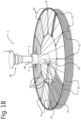
- Figure 1B shows a schematic perspective view of a simplified version of the first exemplary, non-limiting embodiment of a semi-submersible spar-type offshore fish farm 1 shown in figure 1A .
- Figure 1B shows that a first set of elongated connecting elements 9 is provided.
- Each elongated connecting element of the first set of elongated connecting elements 9 is arranged to interconnect the buoyancy sleeve 5 and the frame sections of the first set of frame sections of the first frame 8 via at least one detachable and pivotable coupling assembly 10.
- the coupling assembly 10 will be discussed in more detail in relation to figures 2A and 2B .
- the elongated connecting elements of the first set of elongated connecting elements 9 have a tubular lattice structure. This is schematically shown in figures 2A, 2B , 3 and 4 .
- the elongated connecting elements are configured to carry at least their own weight and at least part of the weight of at least one of the nets of the semi-submersible netted rigid cage 7 that are connected to them and the respective first frame 8 and the second frame 11 of the semi-submersible netted rigid cage 7.
- Figure 1A also shows that for the sake of stability of the semi-submersible netted rigid cage 7, end parts of the elongated connecting elements of the first set of elongated connecting elements 9 that are connected with the first frame 8 are also connected with the buoyancy sleeve 5 via a plurality of guy ropes, e.g. steel wire ropes.
- guy ropes e.g. steel wire ropes.
- Figure 1A shows that the cage 7 further comprises a second frame 11 that is coaxially arranged around the elongated center column 2 and is arranged below the first frame 8.
- the second frame 11 comprises a second set of frame sections 20 that are connected to each other to form a second closed structure.
- the second frame 11 has buoyant properties and has a circular shape. The buoyant properties can be provided in any suitable way, for example by using a tubular lattice structure for the frame sections of the second set of frame sections 20 of the second frame 11.
- Figure 1A also shows that a second set of elongated connecting elements 12 is provided.
- Each elongated connecting element of the second set of elongated connecting elements 12 is arranged to interconnect the first frame 8 and the second frame 11.
- the elongated connecting elements of the second set of elongated connecting elements 12 can be flexible elements such as chains of metal or any other suitable material such as fiber-enforced resilient material.
- Figure 1A further shows that the cage 7 also comprises a third frame 13 that is coaxially arranged around the elongated center column 2 between the first frame 8 and the second frame 11.
- the third frame 13 comprises a third set of frame sections 21 that are connected to each other to form a third closed structure.
- the third frame 13 has buoyant properties and has a circular shape. The buoyant properties can be provided in any suitable way, for example by using a tubular lattice structure for the frame sections of the third set of frame sections 21 of the first frame 13.
- a third set of elongated connecting elements 14 is provided.
- Each elongated connecting element of the third set of elongated connecting elements 14 is arranged to interconnect the harvesting sleeve 6 and the third frame 13 via at least one detachable and pivotable coupling assembly 10.
- the elongated connecting elements are configured to carry at least their own weight and at least part of the weight of at least one of the nets of the semi-submersible netted rigid cage 7 that are connected to them.
- Figure 1B shows that the first exemplary, non-limiting embodiment of the semi-submersible spar-type offshore fish farm 1 is provided with a first platform 22 that is arranged adjacent to the elongated center column 2 and a second platform 23 that is connected with the first frame 8.
- the first platform 22 and the second platform 23 can be used by operators of the semi-submersible spar-type offshore fish farm.
- the first platform 22 and the second platform 23 are interconnected by a walkway that is arranged on an elongated connecting element of the first set of elongated connecting elements 9.
- Figure 1B shows that the first frame 8 is provided with a first net 24 that provides a top net of the semi-submersible netted rigid cage 7.
- first frame 8 and the second frame 11 are also interconnected via a second net 25 that provides a circumferential side net of said cage 7.
- second frame 11 is provided with a third net 26 that provides a bottom net of said cage 7.
- third frame 13 is provided with a fourth net 27 that provides a harvesting net of said cage 7.
- each one of the nets 24, 25, 26, 27 can comprise one or more parts depending on the requirements of the fish farm.
- the first frame 8 is arrangeable along the elongated center column 2 at positions above and below sea level.
- the second frame 11 is arrangeable along the elongated center column 2 at positions below sea level and that the third frame 13 is arrangeable along the elongated center column 2 at positions between the first frame 8 and the second frame 11.
- the person skilled in the art will appreciate that depending on sea conditions it is possible to position the semi-submersible netted rigid cage 7 partially above sea level, for example for harvesting fish during calm sea conditions, and to position said cage completely below sea level, for example when heavy storms or typhoons are expected. The latter can be accomplished by ballasting the center column 2 of the fish farm 1.
- ballast tank 31 of the ballast system 29 that is connected with the second end part 4 of the center column 2.
- the buoyancy sleeve 5 at some point is prevented from moving further upwards along the center column 2 by the limiting sleeve 40.
- the semi-submersible netted rigid cage 7 can be moved to a position beyond a top layer of the seawater where the conditions in the top layer have a limited or ideally no negative effect on the cage 7 and the fish stock that is contained within it.
- the harvesting net 27 that is attached to the third frame 13 can be raised towards the sea level by moving the harvesting sleeve 6 towards the buoyancy sleeve 5. After harvesting the desired amount of fish, the harvesting net 27 can be lowered by moving the third frame towards the second end part 4 of the center column 2, for example under the influence of gravity.
- FIG 2A shows a schematic perspective view of a first exemplary, non-limiting embodiment of a detachable and pivotable coupling assembly 10.
- Figure 2B shows a schematic side view of the embodiment of the coupling assembly 10 shown in figure 2A .
- the coupling assembly 10 can be used to connect for example an elongated connecting element of the first set of elongated connecting elements 9 with the buoyancy sleeve 5 of the semi-submersible spar-type fish farm 1 according to the invention.
- This is shown in figures 2A and 2B , wherein the first part 15 of the coupling assembly 10 is connected with a surface of the buoyancy sleeve 5 that in use of the fish farm faces away from the elongated center column.
- the second part 16 of the coupling assembly 10 is arranged at an end part of an elongated connecting element of the first set of elongated connecting elements 9.
- an elongated connecting element of the third set of elongated connecting elements 14 can be connected with the harvesting sleeve 6 in the same way using the detachable and pivotable coupling assembly 10.
- Figures 2A and 2B show that the detachable and pivotable coupling assembly 10 comprises a first part 15 and a second part 16 that are detachably connected via a first coupling element 17 that is arranged to provide a first pivot axis around which the first part 15 and the second part 16 are pivotable with respect to each other.
- the detachable and pivotable coupling assembly 10 is used to connect an elongated connecting element of for example the first set of elongated connecting elements 9 with the buoyancy sleeve 5 that is arranged around the elongated center column of the semi-submersible spar-type fish farm
- the first coupling element 17 allows the first part 15 and the second part 16 to move with respect to each other in radial directions of the elongated center column.
- a gap D can be seen between the first part 15 of the coupling assembly 10 and the elongated connecting element of the first set of elongated connecting elements 9.
- the gap D enables the aforementioned movements of the first part 15 and the second part 16 with respect to each other.
- an elongated connecting element of the third set of elongated connecting elements in use of the fish farm, is pivotable with respect to the harvesting sleeve in radial directions of the elongated center column.
- the first coupling element 17 can be any suitable coupling element that can provide the first pivot axis that enables the abovementioned pivoting movements of the first part 15 and the second part 16 of the coupling assembly 10.
- the coupling assembly 10 can comprise more than one first parts and more than one second parts depending on the requirements for the semi-submersible spar-type offshore fish farm, e.g. for the sake of redundancy to improve reliability.
- figures 2A and 2B show an exemplary, non-limiting embodiment of the tubular lattice structure for the elongated connecting elements of the first set of elongated connecting elements 9.
- the person skilled in the art will appreciate that the elongated connecting elements of the third set of elongated connecting elements can have the same tubular lattice structure.
- FIGS 2A and 2B also show that the second part 16 of the coupling assembly 10 is provided with a second coupling element 18 that is arranged to provide a second pivot axis that is directed transversely with respect to the first pivot axis.
- a second coupling element 18 that is arranged to provide a second pivot axis that is directed transversely with respect to the first pivot axis.
- an elongated connecting element of for example the first set of elongated connecting elements 9, in use of the fish farm is also pivotable with respect to the buoyancy sleeve 5 in circumferential directions of the elongated center column.
- an elongated connecting element of the first set of elongated connecting elements 9 can move with respect to the buoyancy sleeve 5 in orthogonal directions, e.g.
- the movements in radial and circumferential directions of the elongated center column can also be referred to as movements in pitch and yaw. These directions of movement are the most important directions regarding improvement of the life time of the connections between the elongated connecting elements of the first set of elongated connecting elements and the buoyancy sleeve.
- the second coupling element can be any suitable coupling element that can provide a second pivot axis that is directed transversely with respect to the first pivot axis and that enables the abovementioned movements of the elongated connecting elements of the first set of elongated connecting elements and the buoyancy sleeve, and the elongated connecting elements of the third set of elongated connecting elements and the harvesting sleeve.
- Figures 2A and 2B show that the first part 15 and the second part 16 of the detachable and pivotable coupling assembly 10 are both provided with respective receiving elements, in this particular case holes that are configured and arranged to receive the first coupling element 17. In this way the first part 15 and the second part 16 of the coupling assembly 10 can be connected and detached. This allows for assembling the coupling assemblies and thereby semi-submersible netted cage of the fish farm when the fish farm is at its desired location. Hence, at least transportation of the fish farm is less cumbersome. The person skilled in the art will appreciate that the coupling assembly 10 also allows easy disassembly of the semi-submersible netted cage.
- the first coupling element 17 is an elongated pin that is configured and arranged to detachably connect the first part 15 and the second part 16 of the coupling assembly 10.
- the second coupling element 18 is a shaft that is configured and arranged to provide the second pivot axis that is directed transversely with respect to the first pivot axis.
- the person skilled in the art will appreciate that the respective first 17 and second 18 coupling elements can be any suitable components that provide the respective first and second pivot axes described above.
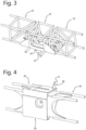
- Figure 3 shows a schematic perspective view of a first exemplary, non-limiting embodiment of a connection of two frame sections of a first set of frame sections 19 of the first frame of the semi-submersible netted rigid cage of the fish farm according to the invention.
- the two frame sections that have a tubular lattice structure to improve the buoyancy properties of the first frame are connected via a first connecting component 33 that also has a tubular lattice structure.
- the first connecting component 33 can be an integral part of an elongated connecting element of the first set of elongated connecting elements.
- first connecting element 33 can be provided with a first part of the coupling assembly that can be detachably connected with a second part of the coupling assembly that is connected with and end part of the elongated connecting element of the first set of connecting elements.
- the first connecting component 33 comprises a first flange 34 that is provided with a first hole 35 that is configured and arranged to receive an end part of an elongated connecting element of the second set of elongated connecting elements for interconnecting the first frame and the second frame of the semi-submersible netted rigid cage.
- Figure 4 shows a schematic perspective view of a first exemplary, non-limiting embodiment of a connection of two frame sections of a second set of frame sections 20 of the second frame of the semi-submersible netted rigid cage of the fish farm according to the invention.
- the two frame sections that have a tubular lattice structure to improve the buoyancy properties of the second frame are connected via a second connecting component 36 that also has a tubular lattice structure.
- the second connecting component 36 can be an integral part of an elongated connecting element of the third set of elongated connecting elements.
- the second connecting element 36 can be provided with a first part of the coupling assembly that can be detachably connected with a second part of the coupling assembly that is connected with and end part of the elongated connecting element of the third set of connecting elements.
- the second connecting component 36 comprises a second flange 37 that is provided with a second hole 38 that is configured and arranged to receive an end part of an elongated connecting element of the second set of elongated connecting elements for interconnecting the first frame and the second frame of the semi-submersible netted rigid cage.
- the present invention can be summarized as relating to a semi-submersible spar-type offshore fish farm 1 for cultivating fish at open sea, comprising an elongated center column 2 having one of a circular and polygonal cross-section.
- the elongated center column comprising a first end part 3 and a second end part 4, a buoyancy sleeve 5 and a harvesting sleeve 6 that are coaxially arranged around the elongated center column, wherein the buoyancy sleeve is arrangeable at positions along the elongated center column between the first end part and the harvesting sleeve and the harvesting sleeve is arrangeable at positions along the elongated center column between the buoyancy sleeve and the second end part.
- Said fish farm further comprises a semi-submersible netted rigid cage 7 that is coaxially arranged around the elongated center column and comprises a first frame 8 that is coaxially arranged around the elongated center column, a first set of elongated connecting elements 9, wherein each of which is arranged to interconnect the buoyancy sleeve and the first frame via at least one detachable and pivotable coupling assembly 10, a second frame 11 that is coaxially arranged around the elongated center column and, in use of said fish farm, is arranged below the first frame, a second set of elongated connecting elements 12, wherein each of which is arranged to interconnect the first frame and the second frame, a third frame 13 that is coaxially arranged around the elongated center column at an adjustable position between the first frame and the second frame, a third set of elongated connecting elements 14, wherein each of which is arranged to interconnect the harvesting sleeve and the third frame via at least one detachable and pivotable coup
Claims (12)
- Halbtauchbare spierenartige Off-Shore Fischzuchtanlage (1) zum Kultivieren von Fisch auf offener See, umfassend:- eine längliche Mittelsäule (2), die eines von einem kreisförmigen und polygonalen Querschnitt aufweist, umfassend:- ein erstes Endteil (3) und ein zweites Endteil (4);- eine Auftriebshülse (5) und eine Erntehülse (6), die koaxial um die längliche Mittelsäule (2) herum angeordnet sind, wobei die Auftriebshülse (5) an Positionen entlang der länglichen Mittelsäule (2) zwischen dem ersten Endteil (3) und der Erntehülse (6) anordenbar ist, und wobei die Erntehülse (6) an Positionen entlang der länglichen Mittelsäule (2) zwischen der Auftriebshülse (5) und dem zweiten Endteil (4) anordenbar ist; und- einen halbtauchbaren netzartigen starren Käfig (7), der um die längliche Mittelsäule (2) herum koaxial angeordnet ist, der Käfig umfassend:- einen ersten Rahmen (8), der um die längliche Mittelsäule (2) herum koaxial angeordnet ist;- einen ersten Satz von länglichen Verbindungselementen (9), wobei jedes längliche Verbindungselement des ersten Satzes von länglichen Verbindungselementen (9) angeordnet ist, um die Auftriebshülse (5) und den ersten Rahmen (8) über mindestens eine abnehmbare und schwenkbare Kopplungsanordnung (10) miteinander zu verbinden;- einen zweiten Rahmen (11), der um die längliche Mittelsäule (2) herum koaxial angeordnet ist, und bei Verwendung der Fischzuchtanlage (1) unter dem ersten Rahmen (8) angeordnet ist;- einen zweiten Satz von länglichen Verbindungselementen (12), wobei jedes längliche Verbindungselement des zweiten Satzes von länglichen Verbindungselementen (12) angeordnet ist, um den ersten Rahmen (8) und den zweiten Rahmen (11) miteinander zu verbinden;- einen dritten Rahmen (13), der um die längliche Mittelsäule (2) herum zwischen dem ersten Rahmen (8) und dem zweiten Rahmen (11) koaxial angeordnet ist;- einen dritten Satz von länglichen Verbindungselementen (14), wobei jedes längliche Verbindungselement des dritten Satzes von länglichen Verbindungselementen (14) angeordnet ist, um die Erntehülse (6) und den dritten Rahmen (13) über mindestens eine abnehmbare und schwenkbare Kopplungsanordnung (10) miteinander zu verbinden,wobei die abnehmbare und schwenkbare Kopplungsanordnung (10) ein erstes Teil (15) und ein zweites Teil (16) umfasst, die über mindestens ein erstes Kopplungselement (17) abnehmbar verbindbar sind, das angeordnet ist, um eine erste Schwenkachse bereitzustellen, um die herum das erste Teil (15) und das zweite Teil (16) in Bezug aufeinander schwenkbar sind,wobei mindestens eines des ersten Teils (15) und des zweiten Teils (16) der abnehmbaren und schwenkbaren Kopplungsanordnung (10) mit mindestens einem zweiten Kopplungselement (18) versehen ist, das angeordnet ist, um eine zweite Schwenkachse bereitzustellen, die in Bezug auf die erste Schwenkachse quer gerichtet ist.
- Halbtauchbare spierenartige Off-Shore Fischzuchtanlage (1) nach Anspruch 1, wobei mindestens einer des ersten Rahmens (8) einen ersten Satz von Rahmenabschnitten (19) umfasst, die miteinander verbunden sind, um eine erste geschlossene Struktur auszubilden, wobei der zweite Rahmen (11) einen zweiten Satz von Rahmenabschnitten (20) umfasst, die miteinander verbunden sind, um eine zweite geschlossene Struktur auszubilden, und der dritte Rahmen (13) einen dritten Satz von Rahmenabschnitten (21) umfasst, die miteinander verbunden sind, um eine dritte geschlossene Struktur auszubilden.
- Halbtauchbare spierenartige Off-Shore Fischzuchtanlage (1) nach einem der vorstehenden Ansprüche, wobei mindestens einer des ersten Rahmens, des zweiten Rahmens und des dritten Rahmens Auftriebseigenschaften aufweisen und eine von einer kreisförmigen und polygonalen Form aufweisen.
- Halbtauchbare spierenartige Off-Shore Fischzuchtanlage (1) nach einem der vorstehenden Ansprüche, wobei das erste Teil (15) der abnehmbaren und schwenkbaren Kopplungsanordnung (10) mindestens an einer von einer Oberfläche der Auftriebshülse (5), die bei Verwendung der Fischzuchtanlage von der länglichen Mittelsäule (2) abgewandt ist, einer Oberfläche der Erntehülse (6), die bei Verwendung der Fischzuchtanlage von der länglichen Mittelsäule (2) abgewandt ist, einer Oberfläche von mindestens einem Rahmenabschnitt des ersten Satzes von Rahmenabschnitten (19) des ersten Rahmens (8), und einer Oberfläche von mindestens einem Rahmenabschnitt des dritten Satzes von Rahmenabschnitten (21) des dritten Rahmens (13), angeordnet ist.
- Halbtauchbare spierenartige Off-Shore Fischzuchtanlage (1) nach einem der vorstehenden Ansprüche, wobei das zweite Teil (16) der abnehmbaren und schwenkbaren Kopplungsanordnung (10) mindestens an einem Endteil eines länglichen Verbindungselements des ersten Satzes von länglichen Verbindungselementen (9) und/oder mindestens an einem Endteil eines länglichen Verbindungselements des dritten Satzes von länglichen Verbindungselementen (14) angeordnet ist.
- Halbtauchbare spierenartige Off-Shore Fischzuchtanlage (1) nach einem der vorstehenden Ansprüche, wobei der halbtauchbare netzartige starre Käfig (7) einen Durchmesser in einem Bereich zwischen 80 m und 180 m aufweist.
- Halbtauchbare spierenartige Off-Shore Fischzuchtanlage (1) nach einem der vorstehenden Ansprüche, wobei die länglichen Verbindungselemente von mindestens einem von dem ersten Satz von länglichen Verbindungselementen (9) und dem zweiten Satz von länglichen Verbindungselementen (14) eine rohrförmige Gitterstruktur aufweisen.
- Halbtauchbare spierenartige Off-Shore Fischzuchtanlage (1) nach einem der vorstehenden Ansprüche, wobei die Fischzuchtanlage (1) mit mindestens einer von einer ersten Plattform (22), die bei Verwendung der Fischzuchtanlage (1) angrenzend an die längliche Mittelsäule (2) angeordnet ist, und einer zweiten Plattform (23), die mit dem ersten Rahmen (8) verbunden ist, angeordnet ist.
- Halbtauchbare spierenartige Off-Shore Fischzuchtanlage (1) nach einem der vorstehenden Ansprüche, wobei der erste Rahmen (8) mit einem ersten Netz (24) versehen ist, das bei Verwendung der Fischzuchtanlage (1) ein oberes Netz des halbtauchbaren netzartigen starren Käfigs (7) bereitstellt, wobei der erste Rahmen (8) und der zweite Rahmen (11) ferner über mindestens ein zweites Netz (25) miteinander verbunden sind, das bei Verwendung der Fischzuchtanlage (1) ein umfangsseitiges Netz des Käfigs (7) bereitstellt, wobei der zweite Rahmen (11) mit einem dritten Netz (26) versehen ist, das bei Verwendung der Fischzuchtanlage (1) ein Bodennetz des Käfigs (7) bereitstellt, und wobei der dritte Rahmen (13) mit einem vierten Netz (27) versehen ist, das bei Verwendung der Fischzuchtanlage (1) ein Erntenetz des Käfigs (7) bereitstellt.
- Halbtauchbare spierenartige Off-Shore Fischzuchtanlage (1) nach einem der vorstehenden Ansprüche, wobei bei Verwendung der Fischzuchtanlage (1) der erste Rahmen (8) entlang der länglichen Mittelsäule (2) an Positionen über und unter Meereshöhe anordenbar ist, wobei der zweite Rahmen (11) entlang der länglichen Mittelsäule (2) an Positionen unter Meereshöhe anordenbar ist, und der dritte Rahmen (13) entlang der länglichen Mittelsäule (2) an Positionen zwischen dem ersten Rahmen (8) und dem zweiten Rahmen (11) anordenbar ist.
- Halbtauchbare spierenartige Off-Shore Fischzuchtanlage (1) nach einem der vorstehenden Ansprüche, wobei das erste Endteil (3) der länglichen Mittelsäule (2) mit einer Steuereinrichtung (28) versehen ist, die bei Verwendung der Fischzuchtanlage (1) über Meereshöhe positioniert bleibt, und das zweite Endteil (4) der länglichen Mittelsäule (2) mit einem Ballastsystem (29) versehen ist, das bei Verwendung der Fischzuchtanlage (1) unter Meereshöhe positioniert bleibt, wobei das Ballastsystem (29) mindestens einen Auftriebstank (30) und mindestens einen Ballasttank (31) umfasst, der mit dem Auftriebsbehälter und mindestens einem Klumpengewicht (32) verbunden ist, das mit dem Auftriebstank verbunden ist.
- Halbtauchbare spierenartige Off-Shore Fischzuchtanlage (1) nach einem der vorstehenden Ansprüche, wobei die halbtauchbare spierenartige Off-Shore Fischzuchtanlage (1) mindestens eines von einem Erntesystem, einem Leistungssystem, einem Verankerungssystem, einem Bootanlegesystem, einem Andocksystem, einem System für eine Entfernung toter Fische und einem Fütterungssystem umfasst.
Applications Claiming Priority (2)
| Application Number | Priority Date | Filing Date | Title |
|---|---|---|---|
| EP17193670 | 2017-09-28 | ||
| PCT/EP2018/076142 WO2019063624A1 (en) | 2017-09-28 | 2018-09-26 | SPAR-TYPE OFFSHORE SEMI-SUBMERSIBLE SWIMMING FARM HAVING A DETACHABLE AND SWIVABLE COUPLING ASSEMBLY |
Publications (2)
| Publication Number | Publication Date |
|---|---|
| EP3687286A1 EP3687286A1 (de) | 2020-08-05 |
| EP3687286B1 true EP3687286B1 (de) | 2024-03-13 |
Family
ID=59974299
Family Applications (1)
| Application Number | Title | Priority Date | Filing Date |
|---|---|---|---|
| EP18772829.0A Active EP3687286B1 (de) | 2017-09-28 | 2018-09-26 | Halbtauchende offshore-fischfarm vom holmtyp mit erfassbarer und schwenkbarer kopplungsanordnung |
Country Status (7)
| Country | Link |
|---|---|
| US (1) | US20210360905A1 (de) |
| EP (1) | EP3687286B1 (de) |
| AU (1) | AU2018342893A1 (de) |
| CA (1) | CA3076857A1 (de) |
| CL (1) | CL2020000803A1 (de) |
| NZ (1) | NZ763744A (de) |
| WO (1) | WO2019063624A1 (de) |
Families Citing this family (6)
| Publication number | Priority date | Publication date | Assignee | Title |
|---|---|---|---|---|
| NO344396B1 (en) * | 2018-11-01 | 2019-11-25 | Mbs Int As | Offshore farming system |
| GB2583130A (en) * | 2019-04-18 | 2020-10-21 | Impact9 Energy And Marine Ltd | A submersible pen system |
| CN110476855B (zh) * | 2019-08-14 | 2021-11-12 | 宁波大学科学技术学院 | 一种深远海海洋牧场 |
| CN111802295B (zh) * | 2020-07-31 | 2023-08-08 | 深圳埃吉尔海洋科技有限公司 | 智能化新能源刚性摇臂连接型深远海养殖综合体 |
| US20220361427A1 (en) * | 2021-05-14 | 2022-11-17 | Fluor Technologies Corporation | Systems and methods for growing and harvesting seaweed using non-producing offshore platforms |
| CN116171904B (zh) * | 2023-03-03 | 2023-08-11 | 上海海事大学 | 一种伞状自升式海洋牧场养殖装置 |
Family Cites Families (5)
| Publication number | Priority date | Publication date | Assignee | Title |
|---|---|---|---|---|
| FR2596613A1 (fr) * | 1986-04-02 | 1987-10-09 | Hardy Luc | Ensemble d'elevage d'animaux aquatiques et plus particulierement de poissons |
| US5617813A (en) * | 1995-03-31 | 1997-04-08 | Ocean Spar Technologies, Llc | Anchorable mobile spar and ring fish pen |
| PT2658368T (pt) * | 2010-12-29 | 2017-02-22 | Oceanspar Inc | Redil para peixe com antena central |
| CN105557572B (zh) * | 2015-12-10 | 2018-08-07 | 青岛迪玛仕船舶技术咨询有限公司 | 一种半潜式单柱海洋工程渔场 |
| EP3419417B1 (de) * | 2016-02-23 | 2023-08-16 | Innovasea Systems, Inc. | Fischbecken für aquakultur mit mortalitätsfalle |
-
2018
- 2018-09-26 AU AU2018342893A patent/AU2018342893A1/en active Pending
- 2018-09-26 CA CA3076857A patent/CA3076857A1/en active Pending
- 2018-09-26 US US16/769,418 patent/US20210360905A1/en not_active Abandoned
- 2018-09-26 WO PCT/EP2018/076142 patent/WO2019063624A1/en unknown
- 2018-09-26 NZ NZ763744A patent/NZ763744A/en unknown
- 2018-09-26 EP EP18772829.0A patent/EP3687286B1/de active Active
-
2020
- 2020-03-27 CL CL2020000803A patent/CL2020000803A1/es unknown
Also Published As
| Publication number | Publication date |
|---|---|
| WO2019063624A1 (en) | 2019-04-04 |
| US20210360905A1 (en) | 2021-11-25 |
| AU2018342893A1 (en) | 2020-05-07 |
| EP3687286A1 (de) | 2020-08-05 |
| CL2020000803A1 (es) | 2021-01-04 |
| NZ763744A (en) | 2023-11-24 |
| CA3076857A1 (en) | 2019-04-04 |
Similar Documents
| Publication | Publication Date | Title |
|---|---|---|
| EP3687286B1 (de) | Halbtauchende offshore-fischfarm vom holmtyp mit erfassbarer und schwenkbarer kopplungsanordnung | |
| EP3426024B1 (de) | Überflutbares system zur fischzucht | |
| JP4464389B2 (ja) | 水没可能囲い網 | |
| CN105557572B (zh) | 一种半潜式单柱海洋工程渔场 | |
| EP3209124B1 (de) | Tauchfähiger käfig für aquakultur und verfahren zur tiefeneinstellung dieser käfig | |
| CN206314415U (zh) | 一种深远海卧式可潜浮单柱形抗台网箱系统 | |
| CN207135969U (zh) | 一种可变形组合式海上浮式养鱼场 | |
| CN113163736A (zh) | 离岸养殖系统 | |
| AU2019210923B2 (en) | Semi-submersible spar-type offshore fish farm with an adjustable ballast system | |
| KR20170012193A (ko) | 김 양식용 자체 건조 장치, 양식 장치 및 조차 자체 건조 방법 | |
| EP3849302B1 (de) | Offshore-fischfarm mit am boden fundamentierten halbtauchfähigen holmen und verfahren zur installation davon | |
| CN109496939B (zh) | 深水漂浮式海洋牧场装置 | |
| CN210519823U (zh) | 一种海洋牧场用养殖平台 | |
| KR20210025008A (ko) | 외해 양식장 | |
| CN110892875A (zh) | 多点系泊系底网笼 | |
| WO2007125363A1 (en) | Fish enclosure | |
| DK179794B1 (en) | Offshore fish farm | |
| RU2669304C1 (ru) | Конструкция для выращивания морских гидробионтов на шельфе и материковом склоне | |
| KR20160120098A (ko) | 부유조립체, 고정형 부유조립체 기구 및 회전식 어구 | |
| NO346662B1 (en) | Submersible fish cage for sea-based farming |
Legal Events
| Date | Code | Title | Description |
|---|---|---|---|
| STAA | Information on the status of an ep patent application or granted ep patent |
Free format text: STATUS: UNKNOWN |
|
| STAA | Information on the status of an ep patent application or granted ep patent |
Free format text: STATUS: THE INTERNATIONAL PUBLICATION HAS BEEN MADE |
|
| PUAI | Public reference made under article 153(3) epc to a published international application that has entered the european phase |
Free format text: ORIGINAL CODE: 0009012 |
|
| STAA | Information on the status of an ep patent application or granted ep patent |
Free format text: STATUS: REQUEST FOR EXAMINATION WAS MADE |
|
| 17P | Request for examination filed |
Effective date: 20200423 |
|
| AK | Designated contracting states |
Kind code of ref document: A1 Designated state(s): AL AT BE BG CH CY CZ DE DK EE ES FI FR GB GR HR HU IE IS IT LI LT LU LV MC MK MT NL NO PL PT RO RS SE SI SK SM TR |
|
| AX | Request for extension of the european patent |
Extension state: BA ME |
|
| DAV | Request for validation of the european patent (deleted) | ||
| DAX | Request for extension of the european patent (deleted) | ||
| GRAP | Despatch of communication of intention to grant a patent |
Free format text: ORIGINAL CODE: EPIDOSNIGR1 |
|
| STAA | Information on the status of an ep patent application or granted ep patent |
Free format text: STATUS: GRANT OF PATENT IS INTENDED |
|
| INTG | Intention to grant announced |
Effective date: 20231026 |
|
| GRAS | Grant fee paid |
Free format text: ORIGINAL CODE: EPIDOSNIGR3 |
|
| GRAA | (expected) grant |
Free format text: ORIGINAL CODE: 0009210 |
|
| STAA | Information on the status of an ep patent application or granted ep patent |
Free format text: STATUS: THE PATENT HAS BEEN GRANTED |
|
| AK | Designated contracting states |
Kind code of ref document: B1 Designated state(s): AL AT BE BG CH CY CZ DE DK EE ES FI FR GB GR HR HU IE IS IT LI LT LU LV MC MK MT NL NO PL PT RO RS SE SI SK SM TR |
|
| REG | Reference to a national code |
Ref country code: GB Ref legal event code: FG4D |
|
| REG | Reference to a national code |
Ref country code: CH Ref legal event code: EP |
|
| REG | Reference to a national code |
Ref country code: DE Ref legal event code: R096 Ref document number: 602018066604 Country of ref document: DE |