EP3687191B1 - Ultrasonic sensor - Google Patents
Ultrasonic sensor Download PDFInfo
- Publication number
- EP3687191B1 EP3687191B1 EP18858712.5A EP18858712A EP3687191B1 EP 3687191 B1 EP3687191 B1 EP 3687191B1 EP 18858712 A EP18858712 A EP 18858712A EP 3687191 B1 EP3687191 B1 EP 3687191B1
- Authority
- EP
- European Patent Office
- Prior art keywords
- internal space
- bottom plate
- ultrasonic sensor
- case
- longitudinal direction
- Prior art date
- Legal status (The legal status is an assumption and is not a legal conclusion. Google has not performed a legal analysis and makes no representation as to the accuracy of the status listed.)
- Active
Links
- 239000000463 material Substances 0.000 claims description 21
- WABPQHHGFIMREM-UHFFFAOYSA-N lead(0) Chemical compound [Pb] WABPQHHGFIMREM-UHFFFAOYSA-N 0.000 description 14
- 239000000758 substrate Substances 0.000 description 6
- 239000011358 absorbing material Substances 0.000 description 5
- 230000000694 effects Effects 0.000 description 5
- 239000002184 metal Substances 0.000 description 5
- 230000001419 dependent effect Effects 0.000 description 4
- 229920005989 resin Polymers 0.000 description 4
- 239000011347 resin Substances 0.000 description 4
- 229920001296 polysiloxane Polymers 0.000 description 3
- 238000001514 detection method Methods 0.000 description 2
- 238000010586 diagram Methods 0.000 description 2
- 229920003002 synthetic resin Polymers 0.000 description 2
- 239000000057 synthetic resin Substances 0.000 description 2
- 230000005540 biological transmission Effects 0.000 description 1
- 238000013016 damping Methods 0.000 description 1
- 239000000428 dust Substances 0.000 description 1
- 239000012212 insulator Substances 0.000 description 1
- 238000004519 manufacturing process Methods 0.000 description 1
- 239000002245 particle Substances 0.000 description 1
- 230000005855 radiation Effects 0.000 description 1
- 230000007704 transition Effects 0.000 description 1
- XLYOFNOQVPJJNP-UHFFFAOYSA-N water Substances O XLYOFNOQVPJJNP-UHFFFAOYSA-N 0.000 description 1
Images


Classifications
-
- G—PHYSICS
- G01—MEASURING; TESTING
- G01S—RADIO DIRECTION-FINDING; RADIO NAVIGATION; DETERMINING DISTANCE OR VELOCITY BY USE OF RADIO WAVES; LOCATING OR PRESENCE-DETECTING BY USE OF THE REFLECTION OR RERADIATION OF RADIO WAVES; ANALOGOUS ARRANGEMENTS USING OTHER WAVES
- G01S7/00—Details of systems according to groups G01S13/00, G01S15/00, G01S17/00
- G01S7/52—Details of systems according to groups G01S13/00, G01S15/00, G01S17/00 of systems according to group G01S15/00
- G01S7/521—Constructional features
-
- H—ELECTRICITY
- H04—ELECTRIC COMMUNICATION TECHNIQUE
- H04R—LOUDSPEAKERS, MICROPHONES, GRAMOPHONE PICK-UPS OR LIKE ACOUSTIC ELECTROMECHANICAL TRANSDUCERS; DEAF-AID SETS; PUBLIC ADDRESS SYSTEMS
- H04R17/00—Piezoelectric transducers; Electrostrictive transducers
-
- G—PHYSICS
- G01—MEASURING; TESTING
- G01S—RADIO DIRECTION-FINDING; RADIO NAVIGATION; DETERMINING DISTANCE OR VELOCITY BY USE OF RADIO WAVES; LOCATING OR PRESENCE-DETECTING BY USE OF THE REFLECTION OR RERADIATION OF RADIO WAVES; ANALOGOUS ARRANGEMENTS USING OTHER WAVES
- G01S15/00—Systems using the reflection or reradiation of acoustic waves, e.g. sonar systems
- G01S15/88—Sonar systems specially adapted for specific applications
- G01S15/93—Sonar systems specially adapted for specific applications for anti-collision purposes
- G01S15/931—Sonar systems specially adapted for specific applications for anti-collision purposes of land vehicles
- G01S2015/937—Sonar systems specially adapted for specific applications for anti-collision purposes of land vehicles sensor installation details
- G01S2015/938—Sonar systems specially adapted for specific applications for anti-collision purposes of land vehicles sensor installation details in the bumper area
Description
- The present invention relates to an ultrasonic sensor.
- The ultrasonic sensor is mounted, for example, on the rear of a vehicle and used as a back sonar. In this case, the ultrasonic sensor transmits ultrasonic waves backward from the vehicle, and then receives the ultrasonic waves reflected and returned from an obstacle behind the vehicle. On the basis of data obtained by electrically processing the relation between the transmitted and received ultrasonic waves, distance information can be determined. As data representing the positional relation of the obstacle relative to the rear of the vehicle, the distance information described above can be used to control the driving of the vehicle. An exemplary ultrasonic sensor that can be used for such purposes is described in
Japanese Unexamined Patent Application Publication No. 2002-209294 - A lack of vertical directivity in the ultrasonic sensor may cause erroneous detection of an unwanted object. To improve detection accuracy of the ultrasonic sensor, a further improvement in vertical directivity is required. The appearance or design of the ultrasonic sensor mounted, for example, on a vehicle is also an issue to be discussed.
-
JP2001-078296 -
JP2001-232294 - We have appreciated that it would be desirable to improve vertical directivity without sacrificing the design of the ultrasonic sensor mounted, for example, on a vehicle.
- The invention is defined in the independent claim to which reference is made. In an aspect of the invention, an ultrasonic sensor based on the present invention includes a cylindrical case having a bottom plate, and a piezoelectric vibrating element mounted on the bottom plate inside the case. The case has an internal space that is a recess extending downward toward the bottom plate. When viewed in a direction perpendicular to the bottom plate, the internal space is of a shape that is longer in one direction than in a direction perpendicular to that direction, having a longitudinal direction parallel to the bottom plate. The case includes a first portion and a second portion. The first portion has a cylindrical shape extending from the bottom plate in the direction perpendicular to the bottom plate, and has a first length which is an outside diameter along the longitudinal direction. The second portion is disposed on a side of the first portion remote from the bottom plate, has a cylindrical shape concentric with the first portion, and has a second length which is an outside diameter along the longitudinal direction and is greater than the first length. A maximum length of a part of the internal space inside the second portion along the longitudinal direction is greater than a maximum length of a part of the internal space inside the first portion along the longitudinal direction. The first portion and the second portion meet at a stepped portion, and the vibrating surface of the ultrasonic sensor comprises the bottom plate and a portion comprising part of the outer wall of the first portion, and a part of the stepped portion parallel to the bottom plate.
- The present invention makes it possible to improve vertical directivity without sacrificing the design of the ultrasonic sensor mounted, for example, on a vehicle.
-
-
Fig. 1 is a first perspective view of an ultrasonic sensor according to a first embodiment based on the present invention. -
Fig. 2 is a second perspective view of the ultrasonic sensor according to the first embodiment based on the present invention. -
Fig. 3 is a cross-sectional view of the ultrasonic sensor according to the first embodiment based on the present invention. -
Fig. 4 is a perspective view of a case included in the ultrasonic sensor according to the first embodiment based on the present invention. -
Fig. 5 is a first plan view of the case included in the ultrasonic sensor according to the first embodiment based on the present invention. -
Fig. 6 is a second plan view of the case included in the ultrasonic sensor according to the first embodiment based on the present invention. -
Fig. 7 is a cross-sectional view as viewed in the direction of arrow VII-VII inFig. 6 . -
Fig. 8 is a cross-sectional view as viewed in the direction of arrow VIII-VIII inFig. 6 . -
Fig. 9 is an explanatory diagram of a portion serving as a vibrating surface in the ultrasonic sensor according to the first embodiment based on the present invention. -
Fig. 10 is a graph showing vertical directivities of a conventional ultrasonic sensor and the ultrasonic sensor according to the first embodiment based on the present invention. -
Fig. 11 is an explanatory diagram illustrating how the ultrasonic sensor according to the first embodiment based on the present invention is mounted and used on the rear of a vehicle. -
Fig. 12 is a perspective view of an ultrasonic sensor according to a second embodiment based on the present invention. -
Fig. 13 is a plan view of a case included in the ultrasonic sensor according to the second embodiment based on the present invention. -
Fig. 14 is a cross-sectional view as viewed in the direction of arrow XIV-XIV inFig. 13 . -
Fig. 15 is a cross-sectional view as viewed in the direction of arrow XV-XV inFig. 13 . -
Fig. 16 is a perspective view of an ultrasonic sensor according to a third embodiment based on the present invention. -
Fig. 17 is a plan view of a case included in the ultrasonic sensor according to the third embodiment based on the present invention. -
Fig. 18 is a cross-sectional view as viewed in the direction of arrow XVIII-XVIII inFig. 17 . -
Fig. 19 is a cross-sectional view as viewed in the direction of arrow XIX-XIX inFig. 17 . -
Fig. 20 is a perspective view of an ultrasonic sensor according to a fourth embodiment based on the present invention. -
Fig. 21 is a plan view of a case included in the ultrasonic sensor according to the fourth embodiment based on the present invention. -
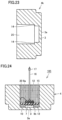
Fig. 22 is a cross-sectional view as viewed in the direction of arrow XXII-XXII inFig. 21 . -
Fig. 23 is a cross-sectional view as viewed in the direction of arrow XXIII-XXIII inFig. 21 . -
Fig. 24 is a cross-sectional view of an ultrasonic sensor according to a fifth embodiment based on the present invention. - Dimensions in the drawings are not necessarily to scale and may be exaggerated for convenience of explanation. In the following description, the concept of "up" or "down" does not necessarily mean "up" or "down" in an absolute sense, and may mean "up" or "down" in a relative sense in the illustrated position.
- With reference to
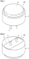
Fig. 1 to Fig. 8 , an ultrasonic sensor according to a first embodiment based on the present invention will be described.Fig. 1 illustrates an outer appearance of anultrasonic sensor 101 according to the present embodiment. Theultrasonic sensor 101 includes acase 4 and twoexternal terminals 8 protruding from thecase 4. Thecase 4 has afront surface 3a. Thefront surface 3a is, for example, circular in shape.Fig. 2 illustrates a back side of theultrasonic sensor 101. Thecase 4 has anopening 19. Theopening 19 is closed by alid 11.Fig. 3 is a cross-sectional view of theultrasonic sensor 101. The twoexternal terminals 8 are positioned to protrude out of a fillingmaterial 12. The twoexternal terminals 8 each pass through thelid 11. Thecase 4 is formed, for example, of metal. Thecase 4 is formed, for example, in an integrated manner. Thecase 4 has abottom plate 3, and thefront surface 3a visible inFig. 1 includes the outer surface of thebottom plate 3. - The
ultrasonic sensor 101 includes thecase 4 cylindrically shaped and having thebottom plate 3, and a piezoelectric vibratingelement 7 mounted on thebottom plate 3 inside thecase 4. Thecase 4 has aninternal space 20 which is a recess extending downward toward thebottom plate 3. Theinternal space 20 is filled with the fillingmaterial 12. Theinternal space 20 is closed by thelid 11. Thelid 11 is formed of, for example, an insulator. Theinternal space 20 is filled with the fillingmaterial 12. As illustrated inFig. 3 , one of the twoexternal terminals 8 is electrically connected to thecase 4 by alead wire 9a, and the other of the twoexternal terminals 8 is electrically connected to the piezoelectric vibratingelement 7 by alead wire 9b. While not illustrated in detail inFig. 3 , the piezoelectric vibratingelement 7 actually includes two electrodes. Of the two electrodes of the piezoelectric vibratingelement 7, one is electrically connected to thelead wire 9b, and the other is electrically connected to thebottom plate 3 of thecase 4. -
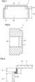
Fig. 4 illustrates thecase 4 taken out independently.Fig. 5 illustrates thecase 4 as viewed from thefront surface 3a. When thecase 4 is viewed in adirection 90 perpendicular to thebottom plate 3, theinternal space 20 is of a shape having alongitudinal direction 91 parallel to thebottom plate 3.Fig. 6 illustrates thecase 4 as viewed from theopening 19.Fig. 7 is a cross-sectional view as viewed in the direction of arrow VII-VII inFig. 6 .Fig. 8 is a cross-sectional view as viewed in the direction of arrow VIII-VIII inFig. 6 . - The
case 4 includes afirst portion 41 and asecond portion 42. Thefirst portion 41 has a cylindrical shape extending from thebottom plate 3 in thedirection 90 perpendicular to thebottom plate 3, and has a first length D1 which is an outside diameter along thelongitudinal direction 91. Thesecond portion 42 is disposed on a side of thefirst portion 41 remote from thebottom plate 3, has a cylindrical shape concentric with thefirst portion 41, and has a second length D2 which is an outside diameter along thelongitudinal direction 91 and is greater than the first length D1. As illustrated inFig. 6 , a maximum length L2 of a part of theinternal space 20 inside thesecond portion 42 along thelongitudinal direction 91 is greater than a maximum length L1 of a part of theinternal space 20 inside thefirst portion 41 along thelongitudinal direction 91. - The
bottom plate 3 serves as a vibrating plate. The piezoelectric vibratingelement 7 vibrates in response to an electric signal applied to the piezoelectric vibratingelement 7. Vibration produced by the piezoelectric vibratingelement 7 vibrates thebottom plate 3 and sends out ultrasonic waves from thefront surface 3a. Ultrasonic waves coming from outside onto thefront surface 3a vibrate thebottom plate 3. By the piezoelectric vibratingelement 7, this vibration can be detected as an electric signal. - The present embodiment can improve the vertical directivity provided by the conventional structure. That is, the present embodiment can narrow the angular range which allows high-sensitivity sensing. The reasons for this will be described in detail below.
- To improve vertical directivity, L1 is preferably increased as much as possible. In the conventional structure, that is, in the structure where L1 and L2 of the
internal space 20 are equal, the vertical directivity is dependent on L1. L1 is a dimension obtained by subtracting a value twice the thickness of the outer wall of thefirst portion 41 from D1, which is the diameter of thefirst portion 41 along thelongitudinal direction 91. This means that the vertical directivity is dependent on the outer shape of thefirst portion 41. The outer shape of thefirst portion 41 cannot be expanded due to limitations associated with, for example, space for installing the ultrasonic sensor. The upper limit of D1 is thus determined. Since the upper limit of L1 is dependent on the upper limit of D1, there has been a limit to the extent to which the vertical directivity of the ultrasonic sensor can be improved. - However, in the present embodiment, where L1 and L2 have different values and L2 is greater than L1, it is possible to increase L2 without changing L1. Therefore, for example, even when D1 is dependent on the space for installing the ultrasonic sensor and this determines the upper limit of L1, it is still possible to increase L2. In the present embodiment, a
portion 45 illustrated inFig. 9 serves as a vibrating surface, along with thebottom plate 3. InFig. 9 , theportion 45 is densely hatched for convenience of explanation. Theportion 45 is composed of the outer wall of thefirst portion 41 and a part of a steppedportion 13 parallel to thebottom plate 3. An imaginary surface surrounded by the outer wall of thesecond portion 42 and parallel to thebottom plate 3 can be regarded as a pseudo vibrating surface. The maximum internal length of thesecond portion 42 along thelongitudinal direction 91 is L2. The vertical directivity can thus be determined by L2, which is greater than L1. The vertical directivity provided by the conventional structure can thus be improved. - When mounted on, for example, a vehicle, the ultrasonic sensor is typically attached to a bumper, with only the
front surface 3a of thebottom plate 3 exposed through a hole in the bumper. Therefore, to discuss the design of the ultrasonic sensor mounted on the vehicle, the diameter of thefront surface 3a is taken into account. In the present embodiment, where there is no need to change D1 to increase L2, the diameter of thefront surface 3a can be kept unchanged. The present embodiment can thus improve vertical directivity without sacrificing the design of the ultrasonic sensor mounted on the vehicle. -
Fig. 10 is a graph that actually compares vertical directivities of an ultrasonic sensor having the conventional structure and theultrasonic sensor 101 according to the present embodiment. Aline 51 represents a vertical directivity obtained by the ultrasonic sensor having the conventional structure. Aline 52 represents a vertical directivity obtained by theultrasonic sensor 101 according to the present embodiment.Fig. 11 illustrates an example of how theultrasonic sensor 101 is mounted and used on the rear of avehicle 60. Amain lobe 61 andside lobes 62 are shown inFig. 11 . Theultrasonic sensor 101 is expected to appropriately detect an obstacle behind thevehicle 60, but is expected not to detect aground 65. Themain lobe 61 and theside lobes 62 each represent a range where an object can be detected with ultrasonic waves. InFig. 10 , three bumps appear in both theline 51 and theline 52. Of the three bumps inFig. 10 , the bump in the center corresponds to themain lobe 61 and the lower bumps on both sides correspond to theside lobes 62. The narrower the width of the bump corresponding to themain lobe 61, the better.Fig. 10 shows that in theline 52, the width of the bump corresponding to themain lobe 61 is narrower than that in theline 51. This means that themain lobe 61 is narrowed and vertical directivity is improved. To prevent theultrasonic sensor 101 from erroneously detecting ultrasonic waves reflected, for example, from theground 65 inFig. 11 , it is preferable that the bumps corresponding to theside lobes 62 be small. InFig. 10 , the lower the bumps corresponding to theside lobes 62, the better.Fig. 10 shows that in theline 52, the bumps corresponding to theside lobes 62 are lower than those in theline 51. This means that with theultrasonic sensor 101 according to the present embodiment, theside lobes 62 are reduced and vertical directivity is improved. - As described in the present embodiment, the part of the
internal space 20 inside thefirst portion 41 and the part of theinternal space 20 inside thesecond portion 42 preferably form the steppedportions 13 at respective ends of theinternal space 20 in thelongitudinal direction 91. This configuration enables an abrupt change in the internal shape in the area of transition from thefirst portion 41 to thesecond portion 42. This can connect thefirst portion 41 and thesecond portion 42 even if there is a significant difference between L1 and L2. - As described in the present embodiment, when viewed in the
direction 90 perpendicular to thebottom plate 3, the contour of theinternal space 20 is preferably curved along the contour of thecase 4 at both ends of theinternal space 20 in thelongitudinal direction 91. This configuration can expand the vibration of the piezoelectric vibratingelement 7 in thelongitudinal direction 91, and can narrow the vertical directivity as a result. - Although the present embodiment shows an example where the
internal space 20 is entirely filled with the fillingmaterial 12 of one type, this is merely an example. Theinternal space 20 may be filled with two or more types of materials combined together. Theinternal space 20 is not necessarily required to be entirely filled with the fillingmaterial 12, and may be partially filled with the fillingmaterial 12. - As described in the present embodiment, the filling
material 12 is preferably disposed to fill at least part of theinternal space 20. This configuration can protect the piezoelectric vibratingelement 7. Depending on how the fillingmaterial 12 is disposed, it is possible to reduce or prevent entry of water or dust particles into the area around the piezoelectric vibratingelement 7. The fillingmaterial 12 may be, for example, silicone. - Although the
opening 19 is closed by thelid 11 in the present embodiment, thelid 11 is optional and the ultrasonic sensor may have a structure without thelid 11. Also, theinternal space 20 is not necessarily required to be filled with the fillingmaterial 12. These conditions are also applicable to the embodiments described below. - With reference to
Fig. 12 to Fig. 15 , an ultrasonic sensor according to a second embodiment based on the present invention will be described.Fig. 12 illustrates an outer appearance of anultrasonic sensor 102 according to the present embodiment. Theultrasonic sensor 102 includes acase 4i and twoexternal terminals 8 protruding from thecase 4i.Fig. 13 is a plan view of thecase 4i.Fig. 14 is a cross-sectional view as viewed in the direction of arrow XIV-XIV inFig. 13 .Fig. 15 is a cross-sectional view as viewed in the direction of arrow XV-XV inFig. 13 . - Like the
case 4 described in the first embodiment, thecase 4i is formed, for example, of metal. The same applies to other cases described in the following embodiments. Like thecase 4 described in the first embodiment, thecase 4i includes thefirst portion 41 and thesecond portion 42. As illustrated inFig. 13 , the maximum length L2 of a part of theinternal space 20 inside thesecond portion 42 along thelongitudinal direction 91 is greater than the maximum length L1 of a part of theinternal space 20 inside thefirst portion 41 along thelongitudinal direction 91. The part of theinternal space 20 inside thefirst portion 41 and the part of theinternal space 20 inside thesecond portion 42 form the steppedportions 13 at respective ends of theinternal space 20 in thelongitudinal direction 91. When a direction perpendicular to thelongitudinal direction 91 is defined as awidth direction 92, the part of theinternal space 20 inside thefirst portion 41 and the part of theinternal space 20 inside thesecond portion 42 form steppedportions 14 at respective ends of theinternal space 20 in thewidth direction 92. Two sides of the steppedportions 14 are linear. The two sides of the steppedportions 14 are parallel to thelongitudinal direction 91. The steppedportions 13 and the steppedportions 14 may be continuous, as illustrated inFig. 13 . - The present embodiment can achieve advantageous effects similar to those of the first embodiment.
- With reference to
Fig. 16 to Fig. 19 , an ultrasonic sensor according to a third embodiment based on the present invention will be described.Fig. 16 illustrates an outer appearance of anultrasonic sensor 103 according to the present embodiment. Theultrasonic sensor 103 includes acase 4j and twoexternal terminals 8 protruding from thecase 4j.Fig. 17 is a plan view of thecase 4j.Fig. 18 is a cross-sectional view as viewed in the direction of arrow XVIII-XVIII inFig. 17 .Fig. 19 is a cross-sectional view as viewed in the direction of arrow XIX-XIX inFig. 17 . - Like the
case 4 described in the first embodiment, thecase 4j includes thefirst portion 41 and thesecond portion 42. As illustrated inFig. 17 , the maximum length L2 of a part of theinternal space 20 inside thesecond portion 42 along thelongitudinal direction 91 is greater than the maximum length L1 of a part of theinternal space 20 inside thefirst portion 41 along thelongitudinal direction 91. As illustrated inFig. 17 , theinternal space 20 is elliptical in shape when viewed in the direction perpendicular to thebottom plate 3. The part of theinternal space 20 inside thefirst portion 41 and the part of theinternal space 20 inside thesecond portion 42 form the steppedportions 13 at respective ends of theinternal space 20 in thelongitudinal direction 91. - The present embodiment can achieve advantageous effects similar to those of the first embodiment.
- With reference to
Fig. 20 to Fig. 23 , an ultrasonic sensor according to a fourth embodiment based on the present invention will be described.Fig. 20 illustrates an outer appearance of anultrasonic sensor 104 according to the present embodiment. Theultrasonic sensor 104 includes acase 4k and twoexternal terminals 8 protruding from thecase 4k.Fig. 21 is a plan view of thecase 4k.Fig. 22 is a cross-sectional view as viewed in the direction of arrow XXII-XXII inFig. 21 .Fig. 23 is a cross-sectional view as viewed in the direction of arrow XXIII-XXIII inFig. 21 . - Like the
case 4 described in the first embodiment, thecase 4k includes thefirst portion 41 and thesecond portion 42. As illustrated inFig. 21 , the maximum length L2 of a part of theinternal space 20 inside thesecond portion 42 along thelongitudinal direction 91 is greater than the maximum length L1 of a part of theinternal space 20 inside thefirst portion 41 along thelongitudinal direction 91. As illustrated inFig. 21 , theinternal space 20 is elliptical in shape when viewed in the direction perpendicular to thebottom plate 3. The part of theinternal space 20 inside thefirst portion 41 and the part of theinternal space 20 inside thesecond portion 42 form the steppedportions 13 at respective ends of theinternal space 20 in thelongitudinal direction 91. The part of theinternal space 20 inside thefirst portion 41 and the part of theinternal space 20 inside thesecond portion 42 form the steppedportions 14 at respective ends of theinternal space 20 in thewidth direction 92. The steppedportions 13 and the steppedportions 14 may be continuous, as illustrated inFig. 21 . - The present embodiment can achieve advantageous effects similar to those of the first embodiment.
- Of the four configurations of the first to fourth embodiments described above, the configuration of the first embodiment is particularly preferable. That is, as in the first embodiment, when viewed in the direction perpendicular to the
bottom plate 3, it is preferable that theinternal space 20 have two sides parallel to thelongitudinal direction 91, and that between the two sides, the width of the part of theinternal space 20 inside thefirst portion 41 be equal to the width of the part of theinternal space 20 inside thesecond portion 42. In the example illustrated inFig. 6 , the two widths are both W. - With reference to
Fig. 24 , an ultrasonic sensor according to a fifth embodiment based on the present invention will be described.Fig. 24 is a cross-sectional view of anultrasonic sensor 105 according to the present embodiment. Theultrasonic sensor 105 includes thecase 4 and onelead wire 16 protruding from thecase 4. The piezoelectric vibratingelement 7 is mounted on thebottom plate 3 of thecase 4. Theinternal space 20 of thecase 4 is divided into three layers. The layer closest to thebottom plate 3 is filled with the fillingmaterial 12. The fillingmaterial 12 may be, for example, silicone. A sound-absorbingmaterial 15 is disposed in the layer second closest to thebottom plate 3. Asubstrate 10 is disposed on the surface of the sound-absorbingmaterial 15. The layer farthest from thebottom plate 3 is filled with the fillingmaterial 12. The sound-absorbingmaterial 15 may be, for example, either felt or silicone sponge. A part of thelead wire 16 is disposed in theinternal space 20 of thecase 4, and the other part of thelead wire 16 extends out of thecase 4. Thelead wire 16 is electrically connected at one end thereof to thesubstrate 10. The portion of thelead wire 16 connected to thesubstrate 10 is covered with the fillingmaterial 12. Thelead wire 16 is provided with aconnector 17 at the other end thereof. Thelead wire 16 includes at least two wires therein. A first wire on the surface of thesubstrate 10 is connected to thecase 4 by thelead wire 9a, and a second wire on the surface of thesubstrate 10 is connected to the piezoelectric vibratingelement 7 by thelead wire 9b. As in the example illustrated inFig. 24 , thelid 11 may not be provided and the upper surface of the fillingmaterial 12 may be directly exposed to the outside. Alternatively, a lid may be disposed to cover the upper surface of the fillingmaterial 12. - The present embodiment can achieve advantageous effects similar to those of the first embodiment. With the sound-absorbing
material 15 disposed in theinternal space 20 as described in the present embodiment, for example, back radiation from the piezoelectric vibratingelement 7 can be reduced and a dereverberation effect can be achieved. - Some of the embodiments described above may be appropriately employed in combination.
- The embodiments disclosed herein are illustrative, not restrictive, in all aspects. The scope of the present invention is defined by the appended claims.
- 3 bottom plate, 3a front surface, 4, 4i, 4j case, 7 piezoelectric vibrating element, 8 external terminal, 9a, 9b lead wire, 10 substrate, 11 lid, 12 filling material, 13, 14 stepped portion, 15 sound-absorbing material, 16 lead wire, 17 connector, 19 opening, 20 internal space, 41 first portion, 42 second portion, 45 portion, 51, 52 line, 60 vehicle, 61 main lobe, 62 side lobe, 65 ground, 90 direction (perpendicular to bottom plate), 91 longitudinal direction, 92 width direction, 101, 102, 103, 104, 105 ultrasonic sensor
Claims (5)
- An ultrasonic sensor (101) comprising:a cylindrical case (4) having a bottom plate (3); anda piezoelectric vibrating element (7) mounted on the bottom plate (3) inside the case (4),wherein the (4) case has an internal space (20) that is a recess extending downward toward the bottom plate (3);when viewed in a direction perpendicular to the bottom plate (3), the internal space (20) is of a shape that is longer in one direction than in a direction perpendicular to that direction, having a longitudinal direction (91) parallel to the bottom plate (3);the case (4) includesa first portion (41) having a cylindrical shape extending from the bottom plate (3) in the direction perpendicular to the bottom plate (3), the first portion (41) having a first length (D1) being an outside diameter along the longitudinal direction, anda second portion (42) disposed on a side of the first portion (41) remote from the bottom plate (3), having a cylindrical shape concentric with the first portion (41), and having a second length (D2) being an outside diameter along the longitudinal direction (42), the second length (D2) being greater than the first length (D1); anda maximum length of a part of the internal space (20) inside the second portion (42) along the longitudinal direction (91) is greater than a maximum length of a part of the internal space inside the first portion (41) along the longitudinal direction (91);wherein the first portion (41) and the second portion (42) meet at a stepped portion (13), and the vibrating surface of the ultrasonic sensor (101) comprises the bottom plate (3) and a portion (45) comprising part of the outer wall of the first portion (41), and a part of the stepped portion (13) parallel to the bottom plate (3).
- The ultrasonic sensor according to claim 1, wherein the part of the internal space (20) inside the first portion (41) and the part of the internal space inside the second portion (42) form the stepped portions (13) at respective ends of the internal space in the longitudinal direction (91).
- The ultrasonic sensor according to claim 1 or 2, wherein when viewed in the direction perpendicular to the bottom plate, a contour of the internal space is curved along a contour of the case at both ends of the internal space in the longitudinal direction.
- The ultrasonic sensor according to any one of claims 1 to 3, wherein a filling material (12) is disposed to fill at least part of the internal space.
- The ultrasonic sensor according to any one of claims 1 to 4, wherein when viewed in the direction perpendicular to the bottom plate (3), the internal space (20) has two sides parallel to the longitudinal direction and, between the two sides, the part of the internal space inside the first portion (41) has the same width (W) as the part of the internal space (20) inside the second portion (42) .
Applications Claiming Priority (2)
| Application Number | Priority Date | Filing Date | Title |
|---|---|---|---|
| JP2017181380 | 2017-09-21 | ||
| PCT/JP2018/030840 WO2019058842A1 (en) | 2017-09-21 | 2018-08-21 | Ultrasonic sensor |
Publications (3)
| Publication Number | Publication Date |
|---|---|
| EP3687191A1 EP3687191A1 (en) | 2020-07-29 |
| EP3687191A4 EP3687191A4 (en) | 2021-06-16 |
| EP3687191B1 true EP3687191B1 (en) | 2024-05-15 |
Family
ID=65811372
Family Applications (1)
| Application Number | Title | Priority Date | Filing Date |
|---|---|---|---|
| EP18858712.5A Active EP3687191B1 (en) | 2017-09-21 | 2018-08-21 | Ultrasonic sensor |
Country Status (5)
| Country | Link |
|---|---|
| US (1) | US20200200885A1 (en) |
| EP (1) | EP3687191B1 (en) |
| JP (1) | JP6863466B2 (en) |
| CN (1) | CN111133772A (en) |
| WO (1) | WO2019058842A1 (en) |
Families Citing this family (5)
| Publication number | Priority date | Publication date | Assignee | Title |
|---|---|---|---|---|
| TWI707146B (en) * | 2019-06-12 | 2020-10-11 | 千竣科技有限公司 | Ultrasonic sensing device |
| JP7318495B2 (en) * | 2019-11-15 | 2023-08-01 | Tdk株式会社 | Ultrasonic device and fluid detection device |
| JPWO2021256047A1 (en) * | 2020-06-17 | 2021-12-23 | ||
| USD1024818S1 (en) * | 2021-04-16 | 2024-04-30 | Chengdu Huitong West Electronic Co., Ltd. | Housing of ultrasonic sensor |
| USD1024814S1 (en) * | 2022-07-05 | 2024-04-30 | Chengdu Huitong West Electronic Co., Ltd. | Housing of ultrasonic sensor |
Family Cites Families (19)
| Publication number | Priority date | Publication date | Assignee | Title |
|---|---|---|---|---|
| TW345132U (en) * | 1998-03-26 | 1998-11-11 | shi-xiong Li | Improved structure for sensor of car backing radar |
| US6250162B1 (en) * | 1998-04-24 | 2001-06-26 | Murata Manufacturing Co., Ltd. | Ultrasonic sensor |
| JP3552605B2 (en) * | 1999-08-31 | 2004-08-11 | 松下電工株式会社 | Ultrasonic transducer |
| JP4304556B2 (en) * | 1999-12-03 | 2009-07-29 | 株式会社村田製作所 | Ultrasonic sensor |
| JP2001232294A (en) * | 2000-02-24 | 2001-08-28 | Matsushita Electric Works Ltd | Ultrasonic vibrator |
| JP3659153B2 (en) * | 2000-09-26 | 2005-06-15 | 松下電工株式会社 | Ultrasonic transducer |
| JP2002262383A (en) * | 2000-12-28 | 2002-09-13 | Matsushita Electric Works Ltd | Ultrasonic wave vibrator |
| JP2002209294A (en) | 2001-01-10 | 2002-07-26 | Murata Mfg Co Ltd | Ultrasonic sensor, electronic unit provided with the same and vehicle rear sonar |
| CN101258772B (en) * | 2005-09-09 | 2012-04-25 | 株式会社村田制作所 | Ultrasonic sensor |
| CN101072452A (en) * | 2005-12-27 | 2007-11-14 | 中国科学院声学研究所 | Deep-sea piezoelectric underwater-acoustic transducer and its manufacturing method |
| JP4742924B2 (en) * | 2006-03-15 | 2011-08-10 | 株式会社デンソー | Ultrasonic sensor |
| DE102007008744B4 (en) * | 2006-03-15 | 2012-10-31 | Denso Corporation | ultrasonic sensor |
| JP4893322B2 (en) * | 2006-03-23 | 2012-03-07 | 株式会社デンソー | Ultrasonic sensor |
| JP2007282058A (en) * | 2006-04-10 | 2007-10-25 | Nippon Ceramic Co Ltd | Ultrasonic sensor |
| DE102006050037A1 (en) * | 2006-10-24 | 2008-04-30 | Robert Bosch Gmbh | Ultrasonic transducer for motor vehicle, has damping unit for damping vibrations of wall, arranged in diaphragm pot in edge section of diaphragm and connected with edge section and inner side of wall in force-fitting manner |
| CN101740017A (en) * | 2008-11-12 | 2010-06-16 | 同致电子企业股份有限公司 | Ultrasonic-wave energy converter with dumbbell-shaped cavity |
| JP4656261B2 (en) * | 2008-12-04 | 2011-03-23 | 株式会社村田製作所 | Ultrasonic transducer |
| KR101553869B1 (en) * | 2013-07-02 | 2015-09-17 | 현대모비스 주식회사 | Ultrasonic sensor assembly |
| JP6493415B2 (en) * | 2014-12-26 | 2019-04-03 | 株式会社村田製作所 | Ultrasonic sensor |
-
2018
- 2018-08-21 JP JP2019543490A patent/JP6863466B2/en active Active
- 2018-08-21 WO PCT/JP2018/030840 patent/WO2019058842A1/en unknown
- 2018-08-21 CN CN201880060510.4A patent/CN111133772A/en not_active Withdrawn
- 2018-08-21 EP EP18858712.5A patent/EP3687191B1/en active Active
-
2020
- 2020-02-28 US US16/804,080 patent/US20200200885A1/en not_active Abandoned
Also Published As
| Publication number | Publication date |
|---|---|
| EP3687191A4 (en) | 2021-06-16 |
| EP3687191A1 (en) | 2020-07-29 |
| JPWO2019058842A1 (en) | 2020-08-27 |
| US20200200885A1 (en) | 2020-06-25 |
| WO2019058842A1 (en) | 2019-03-28 |
| JP6863466B2 (en) | 2021-04-21 |
| CN111133772A (en) | 2020-05-08 |
Similar Documents
| Publication | Publication Date | Title |
|---|---|---|
| EP3687191B1 (en) | Ultrasonic sensor | |
| US6250162B1 (en) | Ultrasonic sensor | |
| CN101297591B (en) | Ultrasonic transducer | |
| JP4468262B2 (en) | Obstacle detection device | |
| JP4438667B2 (en) | Ultrasonic sensor and ultrasonic transducer | |
| EP0930607B1 (en) | Ultrasonic sensor comprising a cylindrical case | |
| US4754440A (en) | Ultrasonic transducer | |
| JP4301298B2 (en) | Ultrasonic sensor and method for manufacturing ultrasonic sensor | |
| US7732993B2 (en) | Ultrasonic sensor and method for manufacturing the same | |
| JP2007147319A (en) | Obstacle detection device | |
| US20070204697A1 (en) | Ultrasonic sensor having vibrator mounted on substrate | |
| JP4752715B2 (en) | Ultrasonic sensor | |
| US11503392B2 (en) | Ultrasonic sensor | |
| JP3552605B2 (en) | Ultrasonic transducer | |
| US20060232165A1 (en) | Ultrasonic transmitter-receiver | |
| WO2021029239A1 (en) | Ultrasound sensor | |
| JP2000032594A (en) | Ultrasonic wave transmitter-receiver | |
| JP5950742B2 (en) | Ultrasonic transducer | |
| JP4304556B2 (en) | Ultrasonic sensor | |
| JP7439728B2 (en) | ultrasonic sensor | |
| JP2001337172A (en) | Ultrasonic detector | |
| KR101376347B1 (en) | ultrasonic transducer | |
| JP6611992B2 (en) | Ultrasonic sensor device and obstacle detection device | |
| JP5340432B2 (en) | Ultrasonic sensor | |
| JP7413921B2 (en) | Ultrasonic sensor mounting structure |
Legal Events
| Date | Code | Title | Description |
|---|---|---|---|
| STAA | Information on the status of an ep patent application or granted ep patent |
Free format text: STATUS: THE INTERNATIONAL PUBLICATION HAS BEEN MADE |
|
| PUAI | Public reference made under article 153(3) epc to a published international application that has entered the european phase |
Free format text: ORIGINAL CODE: 0009012 |
|
| STAA | Information on the status of an ep patent application or granted ep patent |
Free format text: STATUS: REQUEST FOR EXAMINATION WAS MADE |
|
| 17P | Request for examination filed |
Effective date: 20200303 |
|
| AK | Designated contracting states |
Kind code of ref document: A1 Designated state(s): AL AT BE BG CH CY CZ DE DK EE ES FI FR GB GR HR HU IE IS IT LI LT LU LV MC MK MT NL NO PL PT RO RS SE SI SK SM TR |
|
| AX | Request for extension of the european patent |
Extension state: BA ME |
|
| DAV | Request for validation of the european patent (deleted) | ||
| DAX | Request for extension of the european patent (deleted) | ||
| REG | Reference to a national code |
Ref country code: DE Ref legal event code: R079 Ref document number: 602018069620 Country of ref document: DE Free format text: PREVIOUS MAIN CLASS: H04R0017000000 Ipc: G01S0007521000 Ref country code: DE Ref legal event code: R079 Free format text: PREVIOUS MAIN CLASS: H04R0017000000 Ipc: G01S0007521000 |
|
| A4 | Supplementary search report drawn up and despatched |
Effective date: 20210517 |
|
| RIC1 | Information provided on ipc code assigned before grant |
Ipc: G01S 7/521 20060101AFI20210510BHEP Ipc: G01S 15/931 20200101ALI20210510BHEP Ipc: H04R 17/00 20060101ALI20210510BHEP |
|
| GRAP | Despatch of communication of intention to grant a patent |
Free format text: ORIGINAL CODE: EPIDOSNIGR1 |
|
| STAA | Information on the status of an ep patent application or granted ep patent |
Free format text: STATUS: GRANT OF PATENT IS INTENDED |
|
| INTG | Intention to grant announced |
Effective date: 20231214 |
|
| GRAS | Grant fee paid |
Free format text: ORIGINAL CODE: EPIDOSNIGR3 |
|
| GRAA | (expected) grant |
Free format text: ORIGINAL CODE: 0009210 |
|
| STAA | Information on the status of an ep patent application or granted ep patent |
Free format text: STATUS: THE PATENT HAS BEEN GRANTED |