EP3686969B1 - Battery electrode piece thermal compounding apparatus and method for using same to carry out thermo-compression bonding on battery electrode piece assembly - Google Patents
Battery electrode piece thermal compounding apparatus and method for using same to carry out thermo-compression bonding on battery electrode piece assembly Download PDFInfo
- Publication number
- EP3686969B1 EP3686969B1 EP19856441.1A EP19856441A EP3686969B1 EP 3686969 B1 EP3686969 B1 EP 3686969B1 EP 19856441 A EP19856441 A EP 19856441A EP 3686969 B1 EP3686969 B1 EP 3686969B1
- Authority
- EP
- European Patent Office
- Prior art keywords
- lamination
- heating
- roller
- lamination roller
- electrode
- Prior art date
- Legal status (The legal status is an assumption and is not a legal conclusion. Google has not performed a legal analysis and makes no representation as to the accuracy of the status listed.)
- Active
Links
Images


Classifications
-
- B—PERFORMING OPERATIONS; TRANSPORTING
- B32—LAYERED PRODUCTS
- B32B—LAYERED PRODUCTS, i.e. PRODUCTS BUILT-UP OF STRATA OF FLAT OR NON-FLAT, e.g. CELLULAR OR HONEYCOMB, FORM
- B32B37/00—Methods or apparatus for laminating, e.g. by curing or by ultrasonic bonding
- B32B37/0046—Methods or apparatus for laminating, e.g. by curing or by ultrasonic bonding characterised by constructional aspects of the apparatus
- B32B37/0053—Constructional details of laminating machines comprising rollers; Constructional features of the rollers
-
- H—ELECTRICITY
- H01—ELECTRIC ELEMENTS
- H01M—PROCESSES OR MEANS, e.g. BATTERIES, FOR THE DIRECT CONVERSION OF CHEMICAL ENERGY INTO ELECTRICAL ENERGY
- H01M4/00—Electrodes
- H01M4/02—Electrodes composed of, or comprising, active material
- H01M4/13—Electrodes for accumulators with non-aqueous electrolyte, e.g. for lithium-accumulators; Processes of manufacture thereof
- H01M4/139—Processes of manufacture
-
- B—PERFORMING OPERATIONS; TRANSPORTING
- B29—WORKING OF PLASTICS; WORKING OF SUBSTANCES IN A PLASTIC STATE IN GENERAL
- B29C—SHAPING OR JOINING OF PLASTICS; SHAPING OF MATERIAL IN A PLASTIC STATE, NOT OTHERWISE PROVIDED FOR; AFTER-TREATMENT OF THE SHAPED PRODUCTS, e.g. REPAIRING
- B29C43/00—Compression moulding, i.e. applying external pressure to flow the moulding material; Apparatus therefor
- B29C43/02—Compression moulding, i.e. applying external pressure to flow the moulding material; Apparatus therefor of articles of definite length, i.e. discrete articles
- B29C43/021—Compression moulding, i.e. applying external pressure to flow the moulding material; Apparatus therefor of articles of definite length, i.e. discrete articles characterised by the shape of the surface
-
- B—PERFORMING OPERATIONS; TRANSPORTING
- B29—WORKING OF PLASTICS; WORKING OF SUBSTANCES IN A PLASTIC STATE IN GENERAL
- B29C—SHAPING OR JOINING OF PLASTICS; SHAPING OF MATERIAL IN A PLASTIC STATE, NOT OTHERWISE PROVIDED FOR; AFTER-TREATMENT OF THE SHAPED PRODUCTS, e.g. REPAIRING
- B29C43/00—Compression moulding, i.e. applying external pressure to flow the moulding material; Apparatus therefor
- B29C43/32—Component parts, details or accessories; Auxiliary operations
- B29C43/52—Heating or cooling
-
- B—PERFORMING OPERATIONS; TRANSPORTING
- B32—LAYERED PRODUCTS
- B32B—LAYERED PRODUCTS, i.e. PRODUCTS BUILT-UP OF STRATA OF FLAT OR NON-FLAT, e.g. CELLULAR OR HONEYCOMB, FORM
- B32B37/00—Methods or apparatus for laminating, e.g. by curing or by ultrasonic bonding
- B32B37/06—Methods or apparatus for laminating, e.g. by curing or by ultrasonic bonding characterised by the heating method
-
- B—PERFORMING OPERATIONS; TRANSPORTING
- B32—LAYERED PRODUCTS
- B32B—LAYERED PRODUCTS, i.e. PRODUCTS BUILT-UP OF STRATA OF FLAT OR NON-FLAT, e.g. CELLULAR OR HONEYCOMB, FORM
- B32B41/00—Arrangements for controlling or monitoring lamination processes; Safety arrangements
-
- H—ELECTRICITY
- H01—ELECTRIC ELEMENTS
- H01M—PROCESSES OR MEANS, e.g. BATTERIES, FOR THE DIRECT CONVERSION OF CHEMICAL ENERGY INTO ELECTRICAL ENERGY
- H01M10/00—Secondary cells; Manufacture thereof
- H01M10/04—Construction or manufacture in general
- H01M10/0404—Machines for assembling batteries
-
- H—ELECTRICITY
- H01—ELECTRIC ELEMENTS
- H01M—PROCESSES OR MEANS, e.g. BATTERIES, FOR THE DIRECT CONVERSION OF CHEMICAL ENERGY INTO ELECTRICAL ENERGY
- H01M10/00—Secondary cells; Manufacture thereof
- H01M10/05—Accumulators with non-aqueous electrolyte
- H01M10/052—Li-accumulators
-
- H—ELECTRICITY
- H01—ELECTRIC ELEMENTS
- H01M—PROCESSES OR MEANS, e.g. BATTERIES, FOR THE DIRECT CONVERSION OF CHEMICAL ENERGY INTO ELECTRICAL ENERGY
- H01M4/00—Electrodes
- H01M4/02—Electrodes composed of, or comprising, active material
- H01M4/04—Processes of manufacture in general
- H01M4/043—Processes of manufacture in general involving compressing or compaction
- H01M4/0435—Rolling or calendering
-
- B—PERFORMING OPERATIONS; TRANSPORTING
- B32—LAYERED PRODUCTS
- B32B—LAYERED PRODUCTS, i.e. PRODUCTS BUILT-UP OF STRATA OF FLAT OR NON-FLAT, e.g. CELLULAR OR HONEYCOMB, FORM
- B32B2457/00—Electrical equipment
- B32B2457/10—Batteries
-
- B—PERFORMING OPERATIONS; TRANSPORTING
- B32—LAYERED PRODUCTS
- B32B—LAYERED PRODUCTS, i.e. PRODUCTS BUILT-UP OF STRATA OF FLAT OR NON-FLAT, e.g. CELLULAR OR HONEYCOMB, FORM
- B32B37/00—Methods or apparatus for laminating, e.g. by curing or by ultrasonic bonding
- B32B37/10—Methods or apparatus for laminating, e.g. by curing or by ultrasonic bonding characterised by the pressing technique, e.g. using action of vacuum or fluid pressure
- B32B37/1054—Regulating the dimensions of the laminate, e.g. by adjusting the nip or platen gap
-
- Y—GENERAL TAGGING OF NEW TECHNOLOGICAL DEVELOPMENTS; GENERAL TAGGING OF CROSS-SECTIONAL TECHNOLOGIES SPANNING OVER SEVERAL SECTIONS OF THE IPC; TECHNICAL SUBJECTS COVERED BY FORMER USPC CROSS-REFERENCE ART COLLECTIONS [XRACs] AND DIGESTS
- Y02—TECHNOLOGIES OR APPLICATIONS FOR MITIGATION OR ADAPTATION AGAINST CLIMATE CHANGE
- Y02E—REDUCTION OF GREENHOUSE GAS [GHG] EMISSIONS, RELATED TO ENERGY GENERATION, TRANSMISSION OR DISTRIBUTION
- Y02E60/00—Enabling technologies; Technologies with a potential or indirect contribution to GHG emissions mitigation
- Y02E60/10—Energy storage using batteries
Definitions
- the present disclosure relates to the technical field of manufacturing of lithium ion batteries, and in particular to a thermal combination (or hot pressing) equipment for electrodes (or battery electrodes) and a method for thermocompression of an electrode lamination (or a battery electrode assembly) using the thermal combination equipment.
- a lithium ion battery is usually manufactured by using a lamination process, and is specifically manufactured using thermal combination lamination. Specifically, before the lamination, it is necessary to heat a positive electrode material strip, a negative electrode material strip, and two separator strips using a heat generation device, and then the above fours strips are laminated by an appropriate pressure so that they are adhered to one another to form an integrated piece.
- the inventors have found through study that a battery cell obtained in the above manner has a tight structure with almost zero gap between a separator and electrodes, which leads to a long electrolyte permeation time in the subsequent electrolyte injection process, which can hardly meet the rapidly increasing demand for power batteries in the new energy market at present. Therefore, how to achieve rapid electrolyte injection in a laminate obtained by thermal combination of the positive electrode material strip, the negative electrode material strip, and the separator strip is a technical problem to be solved urgently.
- a lamination device is known from WO 2018/084491 A1 . It comprises a pattern roller portion for implementing a pattern on an electrode assembly.
- the pattern roller portion comprises a rotating roller arranged on the surface of the electrode assembly so as to emit heat and a pattern cover wound around the outer peripheral surface of the rotating roller so as to partially pressurize the surface of the electrode assembly together with heat transferred from the rotating roller, thereby implementing a pattern.
- the pattern cover comprises a pattern film wound around the outer peripheral surface of the rotating roller and a deformation member provided on the inner surface of the pattern film and deformed by heat transferred from the rotating roller such that the pattern film is wound around the outer peripheral surface of the rotating roller.
- the present invention provides a thermal combination equipment for electrodes and a method for thermocompression of an electrode lamination using the equipment to effectively alleviate the above technical problems, as defined in appended claims 1 to 13.
- Embodiments of the present disclosure may be implemented, for example, in the following manner:
- the first lamination roller has similar shape and size as those of the second lamination roller, and the first lamination roller is provided thereon with a plurality of grooves which have similar shape and size and are sequentially spaced apart from one another.
- the second lamination roller is provided with a plurality of grooves which have similar shape and size and are sequentially spaced apart from one another.
- each groove is an annular groove circumferentially provided at the periphery of the respective lamination roller.
- the driving device comprises a servo motor, a first driving component, and a second driving component, wherein the first driving component is connected with the first lamination roller, the second driving component is connected with the second lamination roller, and the servo motor is connected with both of the first driving component and the second driving component so as to simultaneously drive the first driving component and the second driving component such that the first lamination roller and the second lamination roller are simultaneous driven to rotate, and the first lamination roller and the second lamination roller are rotated at the same peripheral velocity in opposite directions.
- the heating device is disposed at substantially the same level as the gap between the first lamination roller and the second lamination roller.
- the heating device comprises a first heating component and a second heating component disposed opposite to each other, wherein the first heating component is disposed on the first lamination roller, and the second heating component is disposed on the second lamination roller, and a gap between the first heating component and the second heating component is provided at substantially the same level as the gap between the first lamination roller and the second lamination roller, and the distance between the first heating component and the second heating component matches the thickness of the electrode lamination, so that the first heating component and the second heating component can heat the electrode lamination from both sides of the electrode lamination, respectively.
- the first heating component and the second heating component have similar shape and size
- each of the first heating component and the second heating component comprises a heating plate, a heat insulation plate, and a heating wire
- the heating wire is embedded in the heating plate
- the heat insulation plate is disposed on a side of the heating plate away from the heating wire
- the heating plate is disposed such that the heat insulation plate is between the first lamination roller and the heating plate, and a side of the heating plate away from the heat insulation plate, that is, a side of the heating plate on which the heating wire is disposed, faces the to-be-heated electrode lamination so as to heat the electrode lamination.
- the first heating component and/or the second heating component each have a circular or rectangular surface for heating.
- the first heating component and/or the second heating component each have one heating wire, wherein the heating wire is embedded in the heating plate in a serpentine form.
- the first heating component and/or the second heating component each have a plurality of heating wires, and the heating wires are embedded in the heating plate in a parallel and side-by-side manner.
- the thermal combination equipment for electrode further comprises a support seat and a pressing cylinder, wherein the support seat is disposed on the base, and the pressing cylinder is disposed on the support seat and is connected with the first lamination roller such that the first lamination roller applies a downward pressure to the electrode lamination.
- the thermal combination equipment for electrodes further comprises an auxiliary cylinder, a sliding plate, and a connection plate, wherein the auxiliary cylinder is disposed on the support seat, the first lamination roller is disposed on the connection plate, and the connection plate is connected with the support seat via the sliding plate, so that the auxiliary cylinder drives the first lamination roller disposed on the connection plate to slide up and down along the sliding plate to adjust the distance between the first lamination roller and the second lamination roller.
- the thermal combination equipment for electrodes further comprises a transition roller, wherein the transition roller is disposed on the base and is on a side of the electrode lamination device away from the heating device and is configured to convey the laminated electrode lamination.
- the present disclosure further provides a thermal combination equipment for electrodes, which is applicable to thermocompression of an electrode lamination, the thermal combination equipment for electrodes comprising: a base, a heating device, a transition roller, and an electrode lamination device disposed on the base, wherein the heating device is disposed in the electrode lamination device; the electrode lamination device comprises a first lamination roller, a second lamination roller, and a driving device, both the first lamination roller and the second lamination roller are connected with the driving device, the first lamination roller and the second lamination roller are disposed side by side, and a gap allowing an electrode lamination to pass therethrough is provided between the first lamination roller and the second lamination roller, the first lamination roller and the second lamination roller have similar shape and size and an outer surface of each of the first lamination roller and the second lamination roller is provided with a plurality of grooves which are sequentially spaced apart from one another, the heating device is configured to heat the electrode lamination, the heated electrode lamination is conveyed to the gap between the first lamination
- the present disclosure further provides a method for thermocompression of an electrode lamination using the thermal combination equipment for electrodes described above, the method comprising: heating an electrode lamination using the heating device, and conveying the heated electrode lamination to the gap between the first lamination roller and the second lamination roller so that the heated electrode lamination is thermo-laminated by the first lamination roller and the second lamination roller.
- the first lamination roller has similar shape and size as those of the second lamination roller, and the first lamination roller is provided with a plurality of grooves which have similar shape and size and are sequentially spaced apart from one another.
- the second lamination roller is provided with a plurality of grooves which have similar shape and size and are sequentially spaced apart from one another.
- each groove is an annular groove circumferentially provided at the periphery of the respective lamination roller.
- the heating device comprises a first heating component and a second heating component disposed opposite to each other, wherein the first heating component is disposed on the first lamination roller, and the second heating component is disposed on the second lamination roller, and a gap between the first heating component and the second heating component is provided at substantially the same level as the gap between the first lamination roller and the second lamination roller, and the distance between the first heating component and the second heating component matches the thickness of the electrode lamination, so that the first heating component and the second heating component can heat the electrode lamination from both sides of the electrode lamination, respectively.
- the thermal combination equipment for electrodes is provided with a base, a heating device and an electrode lamination device, wherein the electrode lamination device is provided with a first lamination roller, a second lamination roller and a driving device, and a plurality of grooves are provided on the outer surface(s) of the first lamination roller and/or the second lamination roller, so that a laminated electrode lamination obtained by thermocompression of the electrode lamination using the thermal combination equipment for electrodes described above has uncompacted transition zones, by which rapid injection of an electrolyte is achieved, thereby the applicability of the thermal combination equipment for electrodes is improved.
- Reference Numerals 100-thermal combination equipment for electrodes; 110-base; 120-heating device; 122-first heating component; 122a-heating plate; 122b-heat insulation plate; 122c-heating wire; 124-second heating component; 130-electrode lamination device; 132-first lamination roller; 133-groove; 134-second lamination roller; 140-support seat; 150-pressing cylinder; 160-auxiliary cylinder; 170-sliding plate; 180-connection plate; 190-transition roller.
- an embodiment of the present disclosure provides a thermal combination equipment 100 for electrodes, which is applicable to the thermocompression of an electrode lamination.
- the thermal combination equipment 100 for electrodes comprises a base 110, a heating device 120, and an electrode lamination device 130 disposed on the base 110, wherein the heating device 120 is disposed in the electrode lamination device 130.
- the electrode lamination (rolling) device 130 may comprise a first lamination roller 132, a second lamination roller 134, and a driving device, wherein the first lamination roller 132 and the second lamination roller 134 are connected with the driving device, respectively, the first lamination roller 132 and the second lamination roller 134 are disposed side by side (in parallel), and there is a gap allowing an electrode lamination to pass therethrough between the first lamination roller 132 and the second lamination roller 134.
- the heating device 120 is disposed at substantially the same level as the gap between the first lamination roller 132 and the second lamination roller 134. Referring to FIG.
- an outer surface of the first lamination roller 132 is provided with a plurality of grooves 133, and similarly, an outer surface of the second lamination roller 134 may also optionally be provided with a plurality of grooves 133.
- the heating device 120 is configured to heat the electrode lamination, and the heated electrode lamination is conveyed to the gap between the first lamination roller 132 and the second lamination roller 134 so as to be thermo-compressed by the first lamination roller 132 and the second lamination roller 134.
- the electrode lamination may comprise a positive electrode, a first separator (film), a negative electrode, and a second separator (film) which are sequentially disposed in a stacked manner, or the electrode lamination may only comprise a first separator, a negative electrode, and a second separator which are sequentially stacked, and optionally, the electrode lamination may also comprise a plurality of electrodes, wherein each of the electrodes is provided with separators on both sides thereof.
- the electrode lamination is heated using the heating device 120, and the heated electrode lamination is conveyed to the gap between the first lamination roller 132 and the second lamination roller 134 so as to be thermo-compressed by the first lamination roller 132 and the second lamination roller 134.
- the separator in the obtained laminated electrode lamination has transition zones. Accordingly, when the laminated electrode lamination described above is used for making a battery, an electrolyte can rapidly permeate the laminated electrode lamination through the transition zones, whereby rapid electrolyte injection is achieved, that is to say, the electrolyte permeation time in the subsequent electrolyte injection process is reduced so as to accelerate the entire production process.
- the base 110 may have any shape, and may, for example, have a regular shape such as a rectangular parallelepiped shape, a truncated conical shape, or a cylindrical shape, or the base may have any irregular shape, which is not specifically limited herein.
- the heating device 120 may heat the electrode lamination at a temperature including, but not limited to, 80 °C, 90 °C, 110 °C, and 130 °C; and in addition, the heating temperature may also be adjusted according to actual requirements.
- the number of the heating devices 120 may be one or more, and the heating device 120 may have any shape or size as long as the heating of the electrode lamination can be achieved.
- the heating device 120 may comprise a first heating component 122 and a second heating component 124 disposed opposite to each other, wherein the first heating component 122 is disposed on the first lamination roller 132, and the second heating component 124 is disposed on the second lamination roller 134 such that a gap between the first heating component 122 and the second heating component 124 is at substantially the same level as the gap between the first lamination roller 132 and the second lamination roller 134.
- the distance between the first heating component 122 and the second heating component 124 matches the thickness of the electrode lamination, so that the first heating component 122 and the second heating component 124 can heat the electrode lamination from both sides of the electrode lamination, respectively.
- first heating component 122 and the second heating component 124 may have the same or different shapes and sizes.
- the first heating component 122 and the second heating component 124 are identical in both shape and size.
- the specific structure of the first heating component 122 will be described in detail in the present disclosure. Referring to FIG.
- the first heating component 122 comprises a heating plate 122a, a heat insulation plate 122b, and heating wire 122c, wherein the heating wire 122c is embedded in the heating plate 122a, the heat insulation plate 122b is disposed on a side of the heating plate 122b away from the heating wire 122c, and the heating plate 122a is disposed such that the heat insulation plate 122b is between the first lamination roller 132 and the heating plate, such that a side of the heating plate 122a remote from the heat insulation plate 122b, that is, the side surface of the heating plate 122a on which the heating wire 122c is disposed, faces the to-be-heated electrode lamination so as to heat the electrode lamination.
- the surface of the heating plate 122a which is used for heating may have a regular shape such as a circle or a rectangle, or may have any irregular shape, and optionally, one or more heating wires 122c may be provided.
- the heating plate 122a has a rectangular surface for heating is exemplarily shown.
- the heating wire 122c may optionally be embedded in the heating plate 122a in a serpentine form.
- the plurality of heating wires 122c may optionally be embedded in the heating plate 122a in parallel side by side.
- the electrode lamination is heated simultaneously by using the first heating component 122 and the second heating component 124, thus the electrodes and the separators in the electrode lamination can be uniformly heated to improve the uniformity of adhesion of the electrodes.
- the heat insulation plate 122b is provided such that it is possible to effectively avoid scalding of a user during the user's operation, and to avoid a situation where heat generated by the heating plate 122a adversely affects other components.
- the first lamination roller 132 and the second lamination roller 134 may have the same or different shapes and sizes.
- the first lamination roller 132 and the second lamination roller 134 may have the same number or different numbers of grooves 133; and the grooves 133 on the first lamination roller 132 and the grooves 133 on the second lamination roller 134 may have the same or different shapes and sizes.
- the plurality of grooves 133 on each of the first lamination roller 132 and the second lamination roller 134 may also have the same or different shapes and sizes.
- the first lamination roller 132 has similar shape and size as those of the second lamination roller 134, and the plurality of grooves 133 provided on the first lamination roller 132 have similar shape and size and are sequentially disposed spaced apart from one another.
- each groove 133 may be a strip groove or an annular groove, which is not specifically limited herein.
- the grooves 133 are annular grooves is exemplarily shown, wherein the annular grooves are provided on the first lamination roller 132 and/or the second lamination roller 134 at positions by which it can be ensured that both ends of each of all the electrode laminations which have different widths in a lamination (pressing) range are thermally combined while a portion near the intermediate position between the both ends is spaced apart, so as to facilitate to picking up of the laminated electrode laminations in a subsequent stage.
- the driving device comprises a servo motor, a first driving component, and a second driving component, wherein the first driving component is connected with the first lamination roller 132, the second driving component is connected with the second lamination roller 134, and the servo motor is connected with both of the first driving component and the second driving component so as to simultaneously drive the first driving component and the second driving component, in this way, the first lamination roller 132 and the second lamination roller 134 are simultaneous driven to rotate, wherein the first lamination roller 132 and the second lamination roller 134 are rotated at the same peripheral velocity in opposite directions (clock-wises).
- the first lamination roller 132 and the second lamination roller 134 are simultaneously driven by the servo motor, thereby obtaining a better lamination effect and at the same time avoiding the problems of cost increase and complicated structure caused by use of different driving devices.
- first driving component and the second driving component described above may be rotary driving shafts or driving bearings.
- the thermal combination equipment 100 for electrodes may further comprise a support seat 140 and a pressing cylinder 150, referring to FIG. 1 .
- the support seat 140 is disposed on the base 110, and the pressing cylinder 150 is disposed on the support seat 140 and connected with the first lamination roller 132 such that the first lamination roller applies a downward pressure to the electrode lamination.
- the thermal combination equipment 100 for electrodes may further comprise an auxiliary cylinder 160, a sliding plate 170, and a connection plate 180.
- the auxiliary cylinder 160 is disposed on the support seat 140, the first lamination roller 132 is disposed on the connection plate 180, and the connection plate 180 is connected with the support seat 140 via the sliding plate 170, so that the auxiliary cylinder 160 drives the first lamination roller 132 disposed on the connection plate 180 to slide up and down along the sliding plate 170 to adjust the distance between the first lamination roller 132 and the second lamination roller 134.
- the thermal combination equipment 100 for electrodes may further comprise a transition roller 190.
- the transition roller 190 is disposed on the base 110 and is on a side of the electrode lamination device 130 away from the heating device 120 and is configured to convey the laminated electrode lamination.
- the thermal combination equipment 100 for electrodes is provided with a base 110, a heating device 120 and an electrode lamination device 130, wherein the electrode lamination device 130 is provided with a first lamination roller 132, a second lamination roller 134 and a driving device, and a plurality of grooves 133 are provided on the outer surface of the first lamination roller 132, so that an electrolyte can be rapidly injected into a laminated electrode lamination obtained by thermocompression of the electrode lamination using the above thermal combination equipment 100 for electrodes, whereby the electrolyte permeation time in the subsequent electrolyte injection process is reduced so as to accelerate the entire production process.
- the pressing cylinder 150 is provided such that the laminated electrode lamination is endowed with a better uniformity and a better lamination effect.
- the auxiliary cylinder 160, the sliding plate 170, the connection plate 180, and the transition roller 190 are provided to adjust the distance between the first lamination roller 132 and the second lamination roller 134, whereby it is possible to perform thermocompression on different electrode laminations, so that the thermal combination equipment 100 for electrodes has a higher applicability.
- the present disclosure provides a thermal combination equipment for electrodes.
- An electrode lamination obtained using the equipment enables an electrolyte to be rapidly injected therein and is endowed with a better uniformity and a better lamination effect, and the equipment is applicable to lamination of different electrodes, has high applicability, and can effectively meet the rapidly increasing demand for batteries in the new energy market.
- the equipment has a simple structure, which contributes to a significant reduction of the production cost.
Landscapes
- Engineering & Computer Science (AREA)
- Chemical & Material Sciences (AREA)
- Manufacturing & Machinery (AREA)
- Chemical Kinetics & Catalysis (AREA)
- Electrochemistry (AREA)
- General Chemical & Material Sciences (AREA)
- Mechanical Engineering (AREA)
- Materials Engineering (AREA)
- Battery Electrode And Active Subsutance (AREA)
- Secondary Cells (AREA)
Description
- The present disclosure relates to the technical field of manufacturing of lithium ion batteries, and in particular to a thermal combination (or hot pressing) equipment for electrodes (or battery electrodes) and a method for thermocompression of an electrode lamination (or a battery electrode assembly) using the thermal combination equipment.
- At present, a lithium ion battery is usually manufactured by using a lamination process, and is specifically manufactured using thermal combination lamination. Specifically, before the lamination, it is necessary to heat a positive electrode material strip, a negative electrode material strip, and two separator strips using a heat generation device, and then the above fours strips are laminated by an appropriate pressure so that they are adhered to one another to form an integrated piece.
- The inventors have found through study that a battery cell obtained in the above manner has a tight structure with almost zero gap between a separator and electrodes, which leads to a long electrolyte permeation time in the subsequent electrolyte injection process, which can hardly meet the rapidly increasing demand for power batteries in the new energy market at present. Therefore, how to achieve rapid electrolyte injection in a laminate obtained by thermal combination of the positive electrode material strip, the negative electrode material strip, and the separator strip is a technical problem to be solved urgently.
- A lamination device according to the background art is known from
WO 2018/084491 A1 . It comprises a pattern roller portion for implementing a pattern on an electrode assembly. The pattern roller portion comprises a rotating roller arranged on the surface of the electrode assembly so as to emit heat and a pattern cover wound around the outer peripheral surface of the rotating roller so as to partially pressurize the surface of the electrode assembly together with heat transferred from the rotating roller, thereby implementing a pattern. The pattern cover comprises a pattern film wound around the outer peripheral surface of the rotating roller and a deformation member provided on the inner surface of the pattern film and deformed by heat transferred from the rotating roller such that the pattern film is wound around the outer peripheral surface of the rotating roller. - The present invention provides a thermal combination equipment for electrodes and a method for thermocompression of an electrode lamination using the equipment to effectively alleviate the above technical problems, as defined in appended claims 1 to 13.
- Embodiments of the present disclosure may be implemented, for example, in the following manner:
- An embodiment of the present disclosure provides a thermal combination equipment for electrodes , which is applicable to thermocompression of an electrode lamination, the thermal combination equipment for electrodes comprising a base, a heating device, and an electrode lamination device disposed on the base, wherein the heating device is disposed in the electrode lamination device;
- the electrode lamination device comprises a first lamination roller, a second lamination roller, and a driving device, wherein both the first lamination roller and the second lamination roller are connected with the driving device, the first lamination roller and the second lamination roller are disposed side by side (in parallel), and a gap allowing an electrode lamination to pass therethrough is provided between the first lamination roller and the second lamination roller, a plurality of grooves are provided on an outer surface(s) of the first lamination roller and/or the second lamination roller, the heating device is configured to heat the electrode lamination, and the heated electrode lamination is conveyed to the gap between the first lamination roller and the second lamination roller so as to be thermo-laminated by the first lamination roller and the second lamination roller.
- Optionally, in the thermal combination equipment for electrodes described above, the first lamination roller has similar shape and size as those of the second lamination roller, and the first lamination roller is provided thereon with a plurality of grooves which have similar shape and size and are sequentially spaced apart from one another.
- Optionally, in the thermal combination equipment for electrodes described above, the second lamination roller is provided with a plurality of grooves which have similar shape and size and are sequentially spaced apart from one another.
- Optionally, in the thermal combination equipment for electrodes described above, each groove is an annular groove circumferentially provided at the periphery of the respective lamination roller.
- Optionally, in the thermal combination equipment for electrodes described above, the driving device comprises a servo motor, a first driving component, and a second driving component, wherein the first driving component is connected with the first lamination roller, the second driving component is connected with the second lamination roller, and the servo motor is connected with both of the first driving component and the second driving component so as to simultaneously drive the first driving component and the second driving component such that the first lamination roller and the second lamination roller are simultaneous driven to rotate, and the first lamination roller and the second lamination roller are rotated at the same peripheral velocity in opposite directions.
- Optionally, in the thermal combination equipment for electrodes described above, the heating device is disposed at substantially the same level as the gap between the first lamination roller and the second lamination roller.
- According to the invention, in the thermal combination equipment for electrodes described above, the heating device comprises a first heating component and a second heating component disposed opposite to each other, wherein the first heating component is disposed on the first lamination roller, and the second heating component is disposed on the second lamination roller, and a gap between the first heating component and the second heating component is provided at substantially the same level as the gap between the first lamination roller and the second lamination roller, and the distance between the first heating component and the second heating component matches the thickness of the electrode lamination, so that the first heating component and the second heating component can heat the electrode lamination from both sides of the electrode lamination, respectively.
- According to the invention, in the thermal combination equipment for electrodes described above, the first heating component and the second heating component have similar shape and size, each of the first heating component and the second heating component comprises a heating plate, a heat insulation plate, and a heating wire, wherein the heating wire is embedded in the heating plate, the heat insulation plate is disposed on a side of the heating plate away from the heating wire, and the heating plate is disposed such that the heat insulation plate is between the first lamination roller and the heating plate, and a side of the heating plate away from the heat insulation plate, that is, a side of the heating plate on which the heating wire is disposed, faces the to-be-heated electrode lamination so as to heat the electrode lamination.
- Optionally, in the thermal combination equipment for electrodes described above, the first heating component and/or the second heating component each have a circular or rectangular surface for heating.
- Optionally, in the thermal combination equipment for electrodes described above, the first heating component and/or the second heating component each have one heating wire, wherein the heating wire is embedded in the heating plate in a serpentine form.
- Optionally, in the thermal combination equipment for electrodes described above, the first heating component and/or the second heating component each have a plurality of heating wires, and the heating wires are embedded in the heating plate in a parallel and side-by-side manner.
- Optionally, in the thermal combination equipment for electrodes described above, the thermal combination equipment for electrode further comprises a support seat and a pressing cylinder, wherein the support seat is disposed on the base, and the pressing cylinder is disposed on the support seat and is connected with the first lamination roller such that the first lamination roller applies a downward pressure to the electrode lamination.
- Optionally, in the thermal combination equipment for electrodes described above, the thermal combination equipment for electrodes further comprises an auxiliary cylinder, a sliding plate, and a connection plate, wherein the auxiliary cylinder is disposed on the support seat, the first lamination roller is disposed on the connection plate, and the connection plate is connected with the support seat via the sliding plate, so that the auxiliary cylinder drives the first lamination roller disposed on the connection plate to slide up and down along the sliding plate to adjust the distance between the first lamination roller and the second lamination roller.
- Optionally, in the thermal combination equipment for electrodes described above, the thermal combination equipment for electrodes further comprises a transition roller, wherein the transition roller is disposed on the base and is on a side of the electrode lamination device away from the heating device and is configured to convey the laminated electrode lamination.
- The present disclosure further provides a thermal combination equipment for electrodes, which is applicable to thermocompression of an electrode lamination, the thermal combination equipment for electrodes comprising: a base, a heating device, a transition roller, and an electrode lamination device disposed on the base, wherein the heating device is disposed in the electrode lamination device;
the electrode lamination device comprises a first lamination roller, a second lamination roller, and a driving device, both the first lamination roller and the second lamination roller are connected with the driving device, the first lamination roller and the second lamination roller are disposed side by side, and a gap allowing an electrode lamination to pass therethrough is provided between the first lamination roller and the second lamination roller, the first lamination roller and the second lamination roller have similar shape and size and an outer surface of each of the first lamination roller and the second lamination roller is provided with a plurality of grooves which are sequentially spaced apart from one another, the heating device is configured to heat the electrode lamination, the heated electrode lamination is conveyed to the gap between the first lamination roller and the second lamination roller so as to be thermo-laminated by the first lamination roller and the second lamination roller, and the transition roller is disposed on the base and is on a side of the electrode lamination device away from the heating device and is configured to convey the laminated electrode lamination. - The present disclosure further provides a method for thermocompression of an electrode lamination using the thermal combination equipment for electrodes described above, the method comprising: heating an electrode lamination using the heating device, and conveying the heated electrode lamination to the gap between the first lamination roller and the second lamination roller so that the heated electrode lamination is thermo-laminated by the first lamination roller and the second lamination roller.
- Optionally, in the method for thermocompression of an electrode lamination described above, the first lamination roller has similar shape and size as those of the second lamination roller, and the first lamination roller is provided with a plurality of grooves which have similar shape and size and are sequentially spaced apart from one another.
- Optionally, in the method for thermocompression of an electrode lamination described above, the second lamination roller is provided with a plurality of grooves which have similar shape and size and are sequentially spaced apart from one another.
- Optionally, in the method for thermocompression of an electrode lamination described above, each groove is an annular groove circumferentially provided at the periphery of the respective lamination roller.
- Optionally, in the method for thermocompression of an electrode lamination described above, the heating device comprises a first heating component and a second heating component disposed opposite to each other, wherein the first heating component is disposed on the first lamination roller, and the second heating component is disposed on the second lamination roller, and a gap between the first heating component and the second heating component is provided at substantially the same level as the gap between the first lamination roller and the second lamination roller, and the distance between the first heating component and the second heating component matches the thickness of the electrode lamination, so that the first heating component and the second heating component can heat the electrode lamination from both sides of the electrode lamination, respectively.
- The thermal combination equipment for electrodes according to the embodiment of the present disclosure is provided with a base, a heating device and an electrode lamination device, wherein the electrode lamination device is provided with a first lamination roller, a second lamination roller and a driving device, and a plurality of grooves are provided on the outer surface(s) of the first lamination roller and/or the second lamination roller, so that a laminated electrode lamination obtained by thermocompression of the electrode lamination using the thermal combination equipment for electrodes described above has uncompacted transition zones, by which rapid injection of an electrolyte is achieved, thereby the applicability of the thermal combination equipment for electrodes is improved.
- In order to enable more apparent and easier understanding of the above objects, features, and advantages of the present disclosure, preferred embodiments will be described below in detail by way of example with reference to the accompanying drawings.
- In order to more clearly illustrate technical solutions of embodiments of the present disclosure, drawings required for use in the embodiments will be described briefly below. It is to be understood that the drawings below are merely illustrative of some embodiments of the present disclosure, and therefore should not be considered as a limitation on the scope thereof. It will be understood by those of ordinary skill in the art that other relevant drawings can also be obtained from these drawings without any inventive effort.
-
FIG. 1 is a schematic structural diagram of a thermal combination equipment for electrodes according to an embodiment of the present disclosure. -
FIG. 2 is another schematic structural diagram of a thermal combination equipment for electrodes according to an embodiment of the present disclosure. -
FIG. 3 is a schematic structural diagram of a first lamination roller according to an embodiment of the present disclosure. -
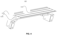
FIG. 4 is a schematic structural diagram of a first heating component according to an embodiment of the present disclosure. - Reference Numerals: 100-thermal combination equipment for electrodes; 110-base; 120-heating device; 122-first heating component; 122a-heating plate; 122b-heat insulation plate; 122c-heating wire; 124-second heating component; 130-electrode lamination device; 132-first lamination roller; 133-groove; 134-second lamination roller; 140-support seat; 150-pressing cylinder; 160-auxiliary cylinder; 170-sliding plate; 180-connection plate; 190-transition roller.
- The technical solutions of the embodiments of the present disclosure will be described below clearly and completely with reference to the accompanying drawings of the embodiments of the present disclosure. It is apparent that the embodiments to be described are some, rather than all of the embodiments of the present disclosure. Generally, the components of the embodiments of the present disclosure, as described and illustrated in the figures herein, may be arranged and designed in a wide variety of different configurations. Thus, the following detailed description of the embodiments of the present disclosure, as represented in the figures, is not intended to limit the scope of the present disclosure as claimed, but is merely representative of selected embodiments of the present disclosure. All the other embodiments obtained by those skilled in the art in light of the embodiments of the present disclosure without inventive efforts shall fall within the scope of the present disclosure as claimed.
- It should be noted that similar reference numerals and letters refer to similar items in the following figures, and thus once an item is defined in one figure, it may not be further defined or explained in the following figures. Moreover, in the description of the present disclosure, terms such as "first" and "second" are used for distinguishing the description only, and should not be understood as an indication or implication of relative importance.
- Referring to
FIG. 1 andFIG. 2 , an embodiment of the present disclosure provides athermal combination equipment 100 for electrodes, which is applicable to the thermocompression of an electrode lamination. Thethermal combination equipment 100 for electrodes comprises abase 110, aheating device 120, and anelectrode lamination device 130 disposed on thebase 110, wherein theheating device 120 is disposed in theelectrode lamination device 130. - Optionally, in the embodiment of the present disclosure, the electrode lamination (rolling)
device 130 may comprise afirst lamination roller 132, asecond lamination roller 134, and a driving device, wherein thefirst lamination roller 132 and thesecond lamination roller 134 are connected with the driving device, respectively, thefirst lamination roller 132 and thesecond lamination roller 134 are disposed side by side (in parallel), and there is a gap allowing an electrode lamination to pass therethrough between thefirst lamination roller 132 and thesecond lamination roller 134. Optionally, theheating device 120 is disposed at substantially the same level as the gap between thefirst lamination roller 132 and thesecond lamination roller 134. Referring toFIG. 3 , optionally, an outer surface of thefirst lamination roller 132 is provided with a plurality ofgrooves 133, and similarly, an outer surface of thesecond lamination roller 134 may also optionally be provided with a plurality ofgrooves 133. Theheating device 120 is configured to heat the electrode lamination, and the heated electrode lamination is conveyed to the gap between thefirst lamination roller 132 and thesecond lamination roller 134 so as to be thermo-compressed by thefirst lamination roller 132 and thesecond lamination roller 134. - It should be noted that, in the embodiment of the present disclosure, the electrode lamination may comprise a positive electrode, a first separator (film), a negative electrode, and a second separator (film) which are sequentially disposed in a stacked manner, or the electrode lamination may only comprise a first separator, a negative electrode, and a second separator which are sequentially stacked, and optionally, the electrode lamination may also comprise a plurality of electrodes, wherein each of the electrodes is provided with separators on both sides thereof.
- When the
thermal combination equipment 100 for electrodes described above is used for performing lamination (compression bonding) on the electrode lamination described above, the electrode lamination is heated using theheating device 120, and the heated electrode lamination is conveyed to the gap between thefirst lamination roller 132 and thesecond lamination roller 134 so as to be thermo-compressed by thefirst lamination roller 132 and thesecond lamination roller 134. Due to thegrooves 133 provided on thefirst lamination roller 132 and/or thesecond lamination roller 134, during the lamination, portions of the electrode lamination which are corresponding to thegrooves 133 are not compacted while a portion of the electrode lamination which is corresponding to a portion between each twoadjacent grooves 133 is compacted, so that the separator in the obtained laminated electrode lamination has transition zones. Accordingly, when the laminated electrode lamination described above is used for making a battery, an electrolyte can rapidly permeate the laminated electrode lamination through the transition zones, whereby rapid electrolyte injection is achieved, that is to say, the electrolyte permeation time in the subsequent electrolyte injection process is reduced so as to accelerate the entire production process. - The base 110 may have any shape, and may, for example, have a regular shape such as a rectangular parallelepiped shape, a truncated conical shape, or a cylindrical shape, or the base may have any irregular shape, which is not specifically limited herein.
- Optionally, the
heating device 120 may heat the electrode lamination at a temperature including, but not limited to, 80 °C, 90 °C, 110 °C, and 130 °C; and in addition, the heating temperature may also be adjusted according to actual requirements. - Optionally, the number of the
heating devices 120 may be one or more, and theheating device 120 may have any shape or size as long as the heating of the electrode lamination can be achieved. - Optionally, in order to uniformly heat the electrode lamination using the
heating device 120, in the embodiment of the present disclosure, referring toFIG. 2 , theheating device 120 may comprise afirst heating component 122 and a second heating component 124 disposed opposite to each other, wherein thefirst heating component 122 is disposed on thefirst lamination roller 132, and the second heating component 124 is disposed on thesecond lamination roller 134 such that a gap between thefirst heating component 122 and the second heating component 124 is at substantially the same level as the gap between thefirst lamination roller 132 and thesecond lamination roller 134. Moreover, the distance between thefirst heating component 122 and the second heating component 124 matches the thickness of the electrode lamination, so that thefirst heating component 122 and the second heating component 124 can heat the electrode lamination from both sides of the electrode lamination, respectively. - Optionally, the
first heating component 122 and the second heating component 124 may have the same or different shapes and sizes. - In order to further improve the effect of heating the electrode lamination by the
heating device 120, in the embodiment of the present disclosure, thefirst heating component 122 and the second heating component 124 are identical in both shape and size. For the convenience of description, only the specific structure of thefirst heating component 122 will be described in detail in the present disclosure. Referring toFIG. 4 , thefirst heating component 122 comprises aheating plate 122a, aheat insulation plate 122b, andheating wire 122c, wherein theheating wire 122c is embedded in theheating plate 122a, theheat insulation plate 122b is disposed on a side of theheating plate 122b away from theheating wire 122c, and theheating plate 122a is disposed such that theheat insulation plate 122b is between thefirst lamination roller 132 and the heating plate, such that a side of theheating plate 122a remote from theheat insulation plate 122b, that is, the side surface of theheating plate 122a on which theheating wire 122c is disposed, faces the to-be-heated electrode lamination so as to heat the electrode lamination. - Optionally, the surface of the
heating plate 122a which is used for heating may have a regular shape such as a circle or a rectangle, or may have any irregular shape, and optionally, one ormore heating wires 122c may be provided. - In the embodiment of the present disclosure, a case where the
heating plate 122a has a rectangular surface for heating is exemplarily shown. When oneheating wire 122c is provided, theheating wire 122c may optionally be embedded in theheating plate 122a in a serpentine form. When a plurality ofheating wires 122c are provided, the plurality ofheating wires 122c may optionally be embedded in theheating plate 122a in parallel side by side. - With the above arrangement, the electrode lamination is heated simultaneously by using the
first heating component 122 and the second heating component 124, thus the electrodes and the separators in the electrode lamination can be uniformly heated to improve the uniformity of adhesion of the electrodes. In addition, theheat insulation plate 122b is provided such that it is possible to effectively avoid scalding of a user during the user's operation, and to avoid a situation where heat generated by theheating plate 122a adversely affects other components. - Optionally, the
first lamination roller 132 and thesecond lamination roller 134 may have the same or different shapes and sizes. Optionally, in the case where both thefirst lamination roller 132 and thesecond lamination roller 134 are provided thereon withgrooves 133, thefirst lamination roller 132 and thesecond lamination roller 134 may have the same number or different numbers ofgrooves 133; and thegrooves 133 on thefirst lamination roller 132 and thegrooves 133 on thesecond lamination roller 134 may have the same or different shapes and sizes. Optionally, the plurality ofgrooves 133 on each of thefirst lamination roller 132 and thesecond lamination roller 134 may also have the same or different shapes and sizes. - In order to achieve a better effect of adhesion between the electrodes and the separators in the obtained laminated electrode lamination, in the embodiment of the present disclosure, the
first lamination roller 132 has similar shape and size as those of thesecond lamination roller 134, and the plurality ofgrooves 133 provided on thefirst lamination roller 132 have similar shape and size and are sequentially disposed spaced apart from one another. - Optionally, each
groove 133 may be a strip groove or an annular groove, which is not specifically limited herein. In the embodiment of the present disclosure, a case where thegrooves 133 are annular grooves is exemplarily shown, wherein the annular grooves are provided on thefirst lamination roller 132 and/or thesecond lamination roller 134 at positions by which it can be ensured that both ends of each of all the electrode laminations which have different widths in a lamination (pressing) range are thermally combined while a portion near the intermediate position between the both ends is spaced apart, so as to facilitate to picking up of the laminated electrode laminations in a subsequent stage. - It can be understood that the number, position(s), groove width, groove depth, and groove shape of the above annular grooves provided are set according to different requirements and occasions, and are not specifically limited herein.
- In order to enable the driving device to synchronously control the
first lamination roller 132 and thesecond lamination roller 134, in the embodiment of the present disclosure, optionally, the driving device comprises a servo motor, a first driving component, and a second driving component, wherein the first driving component is connected with thefirst lamination roller 132, the second driving component is connected with thesecond lamination roller 134, and the servo motor is connected with both of the first driving component and the second driving component so as to simultaneously drive the first driving component and the second driving component, in this way, thefirst lamination roller 132 and thesecond lamination roller 134 are simultaneous driven to rotate, wherein thefirst lamination roller 132 and thesecond lamination roller 134 are rotated at the same peripheral velocity in opposite directions (clock-wises). - With the above arrangement, the
first lamination roller 132 and thesecond lamination roller 134 are simultaneously driven by the servo motor, thereby obtaining a better lamination effect and at the same time avoiding the problems of cost increase and complicated structure caused by use of different driving devices. - It should be noted that, optionally, the first driving component and the second driving component described above may be rotary driving shafts or driving bearings.
- In order to allow the
first lamination roller 132 and thesecond lamination roller 134 to laminate the electrode lamination with uniform pressure so as to endow the laminated electrode lamination with a better lamination effect, in the embodiment of the present disclosure, optionally, thethermal combination equipment 100 for electrodes may further comprise asupport seat 140 and apressing cylinder 150, referring toFIG. 1 . Thesupport seat 140 is disposed on thebase 110, and thepressing cylinder 150 is disposed on thesupport seat 140 and connected with thefirst lamination roller 132 such that the first lamination roller applies a downward pressure to the electrode lamination. - In order to enable thermocompression of different electrode laminations so as to endow the
thermal combination equipment 100 for electrodes with a higher applicability, in the embodiment of the present disclosure, optionally, referring toFIG. 2 , thethermal combination equipment 100 for electrodes may further comprise anauxiliary cylinder 160, a slidingplate 170, and aconnection plate 180. Theauxiliary cylinder 160 is disposed on thesupport seat 140, thefirst lamination roller 132 is disposed on theconnection plate 180, and theconnection plate 180 is connected with thesupport seat 140 via the slidingplate 170, so that theauxiliary cylinder 160 drives thefirst lamination roller 132 disposed on theconnection plate 180 to slide up and down along the slidingplate 170 to adjust the distance between thefirst lamination roller 132 and thesecond lamination roller 134. - In order to avoid the problem of damage of the laminated electrode lamination during its conveyance so as to further improve the applicability of the
thermal combination equipment 100 for electrodes, in the embodiment of the present disclosure, optionally, referring toFIG. 2 , thethermal combination equipment 100 for electrodes may further comprise atransition roller 190. Thetransition roller 190 is disposed on thebase 110 and is on a side of theelectrode lamination device 130 away from theheating device 120 and is configured to convey the laminated electrode lamination. - In summary, the
thermal combination equipment 100 for electrodes according to the present disclosure is provided with abase 110, aheating device 120 and anelectrode lamination device 130, wherein theelectrode lamination device 130 is provided with afirst lamination roller 132, asecond lamination roller 134 and a driving device, and a plurality ofgrooves 133 are provided on the outer surface of thefirst lamination roller 132, so that an electrolyte can be rapidly injected into a laminated electrode lamination obtained by thermocompression of the electrode lamination using the abovethermal combination equipment 100 for electrodes, whereby the electrolyte permeation time in the subsequent electrolyte injection process is reduced so as to accelerate the entire production process. Thepressing cylinder 150 is provided such that the laminated electrode lamination is endowed with a better uniformity and a better lamination effect. Theauxiliary cylinder 160, the slidingplate 170, theconnection plate 180, and thetransition roller 190 are provided to adjust the distance between thefirst lamination roller 132 and thesecond lamination roller 134, whereby it is possible to perform thermocompression on different electrode laminations, so that thethermal combination equipment 100 for electrodes has a higher applicability. - The above description is merely illustrative of specific embodiments of the present disclosure, but the scope of protection of the present disclosure is not limited thereto. Any variations or alternatives that can be readily envisaged by those skilled in the art within the technical scope disclosed in the present disclosure are intended to be encompassed in the scope of protection of the present disclosure. Therefore, the scope of protection of the present disclosure should be determined by the scope of protection of the claims.
- In summary, the present disclosure provides a thermal combination equipment for electrodes. An electrode lamination obtained using the equipment enables an electrolyte to be rapidly injected therein and is endowed with a better uniformity and a better lamination effect, and the equipment is applicable to lamination of different electrodes, has high applicability, and can effectively meet the rapidly increasing demand for batteries in the new energy market. The equipment has a simple structure, which contributes to a significant reduction of the production cost.
Claims (13)
- A thermal combination equipment for electrodes (100), which is applicable to thermocompression of an electrode lamination, wherein the thermal combination equipment for electrodes (100) comprises a base (110), a heating device (120), and an electrode lamination device (130) disposed on the base (110), wherein the heating device (120) is disposed in the electrode lamination device (130);the electrode lamination device (130) comprises a first lamination roller (132), a second lamination roller (134), and a driving device, both the first lamination roller (132) and the second lamination roller (134) are connected with the driving device, the first lamination roller (132) and the second lamination roller (134) are disposed side by side, and a gap allowing an electrode lamination to pass therethrough is provided between the first lamination roller (132) and the second lamination roller (134), a plurality of grooves (133) are provided on an outer surface(s) of the first lamination roller (132) and/or the second lamination roller (134), the heating device (120) is configured to heat the electrode lamination, and the heated electrode lamination is conveyed to the gap between the first lamination roller (132) and the second lamination roller (134) so as to be thermo-laminated by the first lamination roller (132) and the second lamination roller (134),wherein the heating device (120) comprises a first heating component (122) and a second heating component (124) disposed opposite to each other, the first heating component (122) is disposed on the first lamination roller (132), and the second heating component (124) is disposed on the second lamination roller (134), and a gap between the first heating component (122) and the second heating component (124) is provided at a level substantially same as a level at which the gap between the first lamination roller (132) and the second lamination roller (134) is, and a distance between the first heating component (122) and the second heating component (124) matches a thickness of the electrode lamination, so that the first heating component (122) and the second heating component (124) can heat the electrode lamination from both sides of the electrode lamination, respectively,wherein the first heating component (122) and the second heating component (124) have similar shape and size, each of the first heating component (122) and the second heating component (124) comprises a heating plate (122a), a heat insulation plate (122b), and a heating wire (122c), wherein the heating wire is embedded in the heating plate (122a), the heat insulation plate (122b) is disposed on a side of the heating plate (122a) away from the heating wire, and the heating plate (122a) is disposed such that the heat insulation plate (122b) is between the heating plate (122a) and the first lamination roller (132), and a side of the heating plate (122a) away from the heat insulation plate (122b), that is, a side of the heating plate (122a) on which the heating wire is disposed, faces the to-be-heated electrode lamination so as to heat the electrode lamination; and the first heating component (122) and/or the second heating component (124) each have a circular or rectangular surface for heating.
- The thermal combination equipment for electrodes (100) according to claim 1, wherein the first lamination roller (132) has similar shape and size as those of the second lamination roller (134), and the first lamination roller (132) is provided thereon with a plurality of grooves (133) which have similar shape and size and are sequentially spaced apart from one another; and the second lamination roller (134) is provided thereon with a plurality of grooves (133) which have similar shape and size and are sequentially spaced apart from one another.
- The thermal combination equipment for electrodes (100) according to claim 1 or 2, wherein each groove (133) is an annular groove (133) circumferentially provided at the periphery of the respective lamination roller.
- The thermal combination equipment for electrodes (100) according to any one of claims 1 to 3, wherein the driving device comprises a servo motor, a first driving component, and a second driving component, the first driving component is connected with the first lamination roller (132), the second driving component is connected with the second lamination roller (134), and the servo motor is connected with both of the first driving component and the second driving component so as to simultaneously drive the first driving component and the second driving component such that the first lamination roller (132) and the second lamination roller (134) are simultaneous driven to rotate, and the first lamination roller (132) and the second lamination roller (134) are rotated at same peripheral velocity and in opposite directions and the heating device (120) is disposed at a level substantially same as a level at which the gap between the first lamination roller (132) and the second lamination roller (134) is provided.
- The thermal combination equipment for electrodes (100) according to any one of claims 1 to 4, wherein the first heating component (122) and/or the second heating component (124) each have one heating wire and the heating wire is embedded in the heating plate (122a) in a serpentine form.
- The thermal combination equipment for electrodes (100) according to any one of claims 1 to 5, wherein the first heating component (122) and/or the second heating component (124) each have a plurality of heating wires, and the heating wires are embedded in the heating plate (122a) in a parallel and side-by-side manner.
- The thermal combination equipment for electrodes (100) according to any one of claims 1 to 6, wherein the thermal combination equipment for electrodes (100) further comprises a support seat (140) and a pressing cylinder (150), wherein the support seat (140) is disposed on the base (110), and the pressing cylinder (150) is disposed on the support seat (140) and is connected with the first lamination roller (132) such that the first lamination roller (132) apply a downward pressure to the electrode lamination.
- The thermal combination equipment for electrodes (100) according to claim 7, wherein the thermal combination equipment for electrodes (100) further comprises an auxiliary cylinder (160), a sliding plate (170), and a connection plate (180), wherein the auxiliary cylinder (160) is disposed on the support seat (140), the first lamination roller (132) is disposed on the connection plate (180), and the connection plate (180) is connected with the support seat (140) via the sliding plate (170), so that the auxiliary cylinder (160) drives the first lamination roller (132) which is disposed on the connection plate (180) to slide up and down along the sliding plate (170) to adjust the distance between the first lamination roller (132) and the second lamination roller (134).
- The thermal combination equipment for electrodes (100) according to any one of claims 1 to 8, wherein the thermal combination equipment for electrodes (100) further comprises a transition roller (190), and the transition roller (190) is disposed on the base (110) and is on a side of the electrode lamination device (130) away from the heating device (120), the transition roller (190) is configured to convey the laminated electrode lamination.
- The thermal combination equipment for electrodes (100) according to any one of claims 1 to 9, further comprising a transition roller (190);
the transition roller (190) is configured to convey the laminated electrode lamination. - A method for thermocompression of an electrode lamination using the thermal combination equipment for electrodes (100) according to any one of claims 1 to 10, comprising steps of: heating an electrode lamination using the heating device (120), and conveying the heated electrode lamination to the gap between the first lamination roller (132) and the second lamination roller (134) so that the heated electrode lamination is thermo-laminated by the first lamination roller (132) and the second lamination roller (134).
- The method for thermocompression of an electrode lamination according to claim 11, wherein the first lamination roller (132) has the similar shape and size as those of the second lamination roller (134), and the first lamination roller (132) is provided with a plurality of grooves (133) which have similar shape and size and are sequentially spaced apart from one another; and the second lamination roller (134) is provided with a plurality of grooves (133) which have similar shape and size and are sequentially spaced apart from one another, wherein each groove (133) is an annular groove (133) circumferentially provided at the periphery of the respective lamination roller.
- The method for thermocompression of an electrode lamination according to claim 11 or 12, wherein the driving device comprises a servo motor, a first driving component, and a second driving component, the first driving component is connected with the first lamination roller (132), the second driving component is connected with the second lamination roller (134), and the servo motor is connected with both of the first driving component and the second driving component so as to simultaneously drive the first driving component and the second driving component, such that the first lamination roller (132) and the second lamination roller (134) are simultaneous driven to rotate, and the first lamination roller (132) and the second lamination roller (134) are rotated at same peripheral velocity and in opposite directions.
Applications Claiming Priority (2)
| Application Number | Priority Date | Filing Date | Title |
|---|---|---|---|
| CN201811204403.2A CN109244371B (en) | 2018-10-16 | 2018-10-16 | Battery pole piece thermal compounding equipment |
| PCT/CN2019/108678 WO2020078201A1 (en) | 2018-10-16 | 2019-09-27 | Battery electrode piece thermal compounding apparatus and method for using same to carry out thermo-compression bonding on battery electrode piece assembly |
Publications (4)
| Publication Number | Publication Date |
|---|---|
| EP3686969A1 EP3686969A1 (en) | 2020-07-29 |
| EP3686969A4 EP3686969A4 (en) | 2021-08-04 |
| EP3686969B1 true EP3686969B1 (en) | 2024-04-03 |
| EP3686969C0 EP3686969C0 (en) | 2024-04-03 |
Family
ID=65053156
Family Applications (1)
| Application Number | Title | Priority Date | Filing Date |
|---|---|---|---|
| EP19856441.1A Active EP3686969B1 (en) | 2018-10-16 | 2019-09-27 | Battery electrode piece thermal compounding apparatus and method for using same to carry out thermo-compression bonding on battery electrode piece assembly |
Country Status (5)
| Country | Link |
|---|---|
| EP (1) | EP3686969B1 (en) |
| CN (1) | CN109244371B (en) |
| ES (1) | ES2980370T3 (en) |
| HU (1) | HUE067012T2 (en) |
| WO (1) | WO2020078201A1 (en) |
Families Citing this family (9)
| Publication number | Priority date | Publication date | Assignee | Title |
|---|---|---|---|---|
| CN109244371B (en) * | 2018-10-16 | 2024-02-27 | 深圳吉阳智能科技有限公司 | Battery pole piece thermal compounding equipment |
| CN111403817B (en) * | 2020-04-20 | 2025-06-17 | 深圳吉阳智能科技有限公司 | Composite rolls and lamination machines |
| CN112478901A (en) * | 2020-12-09 | 2021-03-12 | 珠海冠宇电池股份有限公司 | Thermal compounding equipment |
| CN113013471B (en) * | 2021-02-23 | 2023-04-14 | 深圳吉阳智能科技有限公司 | Front-mounted heat composite lamination device of oven |
| CN113067026A (en) * | 2021-03-15 | 2021-07-02 | 深圳吉阳智能科技有限公司 | Thermal compounding device for battery lamination |
| CN114309060A (en) * | 2022-01-04 | 2022-04-12 | 刘淑容 | Rolling forming equipment and material production line |
| CN114678599B (en) * | 2022-04-13 | 2026-03-03 | 上海兰钧新能源科技有限公司 | Battery cell thermal compounding equipment and method |
| CN217451483U (en) * | 2022-07-12 | 2022-09-20 | 宁德时代新能源科技股份有限公司 | Rolling device, composite pole piece, battery monomer and electric device |
| CN120171163B (en) * | 2025-05-22 | 2025-08-26 | 邢台德谨精密机械制造有限公司 | Dry electrode forming device with stepped compression roller structure |
Family Cites Families (20)
| Publication number | Priority date | Publication date | Assignee | Title |
|---|---|---|---|---|
| JP2973894B2 (en) * | 1995-05-09 | 1999-11-08 | 松下電器産業株式会社 | Cylindrical battery |
| JP3539044B2 (en) * | 1996-02-05 | 2004-06-14 | ソニー株式会社 | Hot pressing device for strip-shaped members |
| CN1185728C (en) * | 1999-07-21 | 2005-01-19 | 松下电器产业株式会社 | Alkaline storage battery pole plate and production method for alkaline storage battery pole plate and alkaline storage battery |
| ITFI20050130A1 (en) * | 2005-06-10 | 2006-12-11 | Fintex & Partners Italia S P A | METHOD AND MACHINE FOR THE PRODUCTION OF A COMPOSITE MANUFACTURE |
| CN101271269A (en) * | 2007-03-19 | 2008-09-24 | 奥贝达克特公司 | Nano-imprinting apparatus and method |
| JP2010186740A (en) * | 2009-01-16 | 2010-08-26 | Panasonic Corp | Electrode group for nonaqueous battery, its manufacturing method, cylindrical nonaqueous secondary battery and its manufacturing method |
| CN202275887U (en) * | 2011-09-20 | 2012-06-13 | 宜春青山能源有限公司 | Lithium ion power battery pole piece wrinkle resistant roller |
| JP5716622B2 (en) * | 2011-09-26 | 2015-05-13 | 日産自動車株式会社 | Strip electrode manufacturing apparatus and manufacturing method |
| CN102569732B (en) * | 2012-03-16 | 2014-07-02 | 天津力神电池股份有限公司 | Method for automatically repairing extreme differences of rolling rollers of battery pole plate |
| CN204375840U (en) * | 2014-12-17 | 2015-06-03 | 山东精工电子科技有限公司 | A kind of electrodes of lithium-ion batteries rolls dust cleaning apparatus |
| KR102024886B1 (en) * | 2016-11-04 | 2019-11-04 | 주식회사 엘지화학 | Lamination apparatus |
| CN206461050U (en) * | 2016-12-01 | 2017-09-01 | 华太电池(天津)有限公司 | A kind of battery pole powder rolls granulation processing unit |
| KR102109832B1 (en) * | 2017-02-23 | 2020-05-12 | 주식회사 엘지화학 | Plasma generating apparatus for secondary battery and lamination system include the same |
| CN106766787B (en) * | 2017-03-01 | 2023-07-11 | 深圳市新伟创实业有限公司 | Pole piece hot roller drying system |
| CN207116581U (en) * | 2017-09-18 | 2018-03-16 | 深圳市比克动力电池有限公司 | Electrodes of lithium-ion batteries rolling device |
| CN107834021B (en) * | 2017-12-05 | 2023-10-24 | 苏州赛腾菱欧智能科技有限公司 | Rolling adjustment structure of battery piece |
| CN108199005B (en) * | 2018-01-03 | 2020-06-23 | 浙江衡远新能源科技有限公司 | Rolling method and equipment for battery pole piece |
| CN108539126B (en) * | 2018-04-23 | 2024-08-16 | 邢台海裕锂能电池设备有限公司 | Hot rolling device for lithium battery pole piece |
| CN208781946U (en) * | 2018-10-16 | 2019-04-23 | 深圳吉阳智能科技有限公司 | The hot equipment complex of battery pole piece |
| CN109244371B (en) * | 2018-10-16 | 2024-02-27 | 深圳吉阳智能科技有限公司 | Battery pole piece thermal compounding equipment |
-
2018
- 2018-10-16 CN CN201811204403.2A patent/CN109244371B/en active Active
-
2019
- 2019-09-27 WO PCT/CN2019/108678 patent/WO2020078201A1/en not_active Ceased
- 2019-09-27 HU HUE19856441A patent/HUE067012T2/en unknown
- 2019-09-27 EP EP19856441.1A patent/EP3686969B1/en active Active
- 2019-09-27 ES ES19856441T patent/ES2980370T3/en active Active
Also Published As
| Publication number | Publication date |
|---|---|
| HUE067012T2 (en) | 2024-09-28 |
| CN109244371A (en) | 2019-01-18 |
| EP3686969A4 (en) | 2021-08-04 |
| EP3686969A1 (en) | 2020-07-29 |
| CN109244371B (en) | 2024-02-27 |
| EP3686969C0 (en) | 2024-04-03 |
| WO2020078201A1 (en) | 2020-04-23 |
| ES2980370T3 (en) | 2024-10-01 |
Similar Documents
| Publication | Publication Date | Title |
|---|---|---|
| EP3686969B1 (en) | Battery electrode piece thermal compounding apparatus and method for using same to carry out thermo-compression bonding on battery electrode piece assembly | |
| EP3336951B1 (en) | Electrode assembly and method for manufacturing the same | |
| US9484568B2 (en) | Method of manufacturing layered structure constituting all-solid-state battery, apparatus for manufacturing the same, and all-solid-state battery provided with layered structure | |
| CN107683543B (en) | All-solid-state secondary battery and method for manufacturing same | |
| US10862099B2 (en) | Apparatus for enhancing electrolyte wetting in rechargeable battery and electrolyte wetting enhancing method using the same | |
| US20160036087A1 (en) | Method for manufacturing electrode assembly | |
| JP6902731B2 (en) | Battery manufacturing method | |
| TW201711253A (en) | A method for manufacturing a curved electrode assembly | |
| JP7823978B2 (en) | Method and apparatus for laminating battery cell components | |
| KR102839255B1 (en) | Zigzag stacking apparatus for battery electrode | |
| EP3136466B1 (en) | Manufacture method of electrode assembly | |
| JP5277736B2 (en) | Bipolar battery manufacturing method and bipolar battery manufacturing apparatus | |
| CN109560252B (en) | Manufacturing method of electrode stack assembly and electrode stack assembly | |
| US11424474B2 (en) | Secondary battery, and apparatus and method for manufacturing the same | |
| CN106340680A (en) | Method and device for manufacturing laminated battery unit | |
| JP2019102196A (en) | Manufacturing method of battery | |
| KR102654140B1 (en) | Device of manufacturing a secondary battery | |
| JP2016091750A (en) | All-solid-state secondary battery | |
| CN113258141A (en) | Preparation method of laminated battery cell, laminated battery cell and lithium ion battery | |
| CN106575788A (en) | Method and apparatus for forming a wound structure | |
| WO2019013319A1 (en) | Apparatus for manufacturing electrode body | |
| KR102914055B1 (en) | The Apparatus And The Method For Manufacturing Unit Cell | |
| JP2016207448A (en) | Single wafer stacked lithium ion battery manufacturing apparatus and single wafer stacked lithium ion battery manufacturing method | |
| EP4106065B1 (en) | Laminator having improved adhesiveness for producing unit structures | |
| KR20230028977A (en) | Method and equipment for manufacturing laminated film for cell type battery pouch |
Legal Events
| Date | Code | Title | Description |
|---|---|---|---|
| STAA | Information on the status of an ep patent application or granted ep patent |
Free format text: STATUS: UNKNOWN |
|
| STAA | Information on the status of an ep patent application or granted ep patent |
Free format text: STATUS: THE INTERNATIONAL PUBLICATION HAS BEEN MADE |
|
| PUAI | Public reference made under article 153(3) epc to a published international application that has entered the european phase |
Free format text: ORIGINAL CODE: 0009012 |
|
| STAA | Information on the status of an ep patent application or granted ep patent |
Free format text: STATUS: REQUEST FOR EXAMINATION WAS MADE |
|
| 17P | Request for examination filed |
Effective date: 20200311 |
|
| AK | Designated contracting states |
Kind code of ref document: A1 Designated state(s): AL AT BE BG CH CY CZ DE DK EE ES FI FR GB GR HR HU IE IS IT LI LT LU LV MC MK MT NL NO PL PT RO RS SE SI SK SM TR |
|
| AX | Request for extension of the european patent |
Extension state: BA ME |
|
| RAP1 | Party data changed (applicant data changed or rights of an application transferred) |
Owner name: SHENZHEN GEESUN INTELLIGENT TECHNOLOGY CO., LTD. |
|
| RIN1 | Information on inventor provided before grant (corrected) |
Inventor name: CHEN, FEI Inventor name: YANG, JI Inventor name: YANG, RUKUN Inventor name: WEI, HONGSHENG |
|
| A4 | Supplementary search report drawn up and despatched |
Effective date: 20210126 |
|
| RIC1 | Information provided on ipc code assigned before grant |
Ipc: B32B 37/06 20060101ALI20210120BHEP Ipc: B32B 41/00 20060101AFI20210120BHEP |
|
| STAA | Information on the status of an ep patent application or granted ep patent |
Free format text: STATUS: EXAMINATION IS IN PROGRESS |
|
| 17Q | First examination report despatched |
Effective date: 20210510 |
|
| STAA | Information on the status of an ep patent application or granted ep patent |
Free format text: STATUS: REQUEST FOR EXAMINATION WAS MADE |
|
| STAA | Information on the status of an ep patent application or granted ep patent |
Free format text: STATUS: EXAMINATION IS IN PROGRESS |
|
| RA4 | Supplementary search report drawn up and despatched (corrected) |
Effective date: 20210126 |
|
| RIC1 | Information provided on ipc code assigned before grant |
Ipc: B32B 41/00 20060101AFI20210625BHEP Ipc: B32B 37/06 20060101ALI20210625BHEP |
|
| 17Q | First examination report despatched |
Effective date: 20210708 |
|
| DAV | Request for validation of the european patent (deleted) | ||
| DAX | Request for extension of the european patent (deleted) | ||
| REG | Reference to a national code |
Ref country code: DE Ref legal event code: R079 Free format text: PREVIOUS MAIN CLASS: H01M0004139000 Ipc: B32B0041000000 Ref country code: DE Ref legal event code: R079 Ref document number: 602019049711 Country of ref document: DE Free format text: PREVIOUS MAIN CLASS: H01M0004139000 Ipc: B32B0041000000 |
|
| GRAP | Despatch of communication of intention to grant a patent |
Free format text: ORIGINAL CODE: EPIDOSNIGR1 |
|
| STAA | Information on the status of an ep patent application or granted ep patent |
Free format text: STATUS: GRANT OF PATENT IS INTENDED |
|
| RIC1 | Information provided on ipc code assigned before grant |
Ipc: B29C 43/52 20060101ALI20231012BHEP Ipc: H01M 10/052 20100101ALI20231012BHEP Ipc: H01M 4/139 20100101ALI20231012BHEP Ipc: B32B 41/00 20060101AFI20231012BHEP |
|
| INTG | Intention to grant announced |
Effective date: 20231103 |
|
| GRAS | Grant fee paid |
Free format text: ORIGINAL CODE: EPIDOSNIGR3 |
|
| GRAA | (expected) grant |
Free format text: ORIGINAL CODE: 0009210 |
|
| STAA | Information on the status of an ep patent application or granted ep patent |
Free format text: STATUS: THE PATENT HAS BEEN GRANTED |
|
| AK | Designated contracting states |
Kind code of ref document: B1 Designated state(s): AL AT BE BG CH CY CZ DE DK EE ES FI FR GB GR HR HU IE IS IT LI LT LU LV MC MK MT NL NO PL PT RO RS SE SI SK SM TR |
|
| REG | Reference to a national code |
Ref country code: CH Ref legal event code: EP |
|
| REG | Reference to a national code |
Ref country code: IE Ref legal event code: FG4D |
|
| REG | Reference to a national code |
Ref country code: DE Ref legal event code: R096 Ref document number: 602019049711 Country of ref document: DE |
|
| U01 | Request for unitary effect filed |
Effective date: 20240424 |
|
| U07 | Unitary effect registered |
Designated state(s): AT BE BG DE DK EE FI FR IT LT LU LV MT NL PT SE SI Effective date: 20240503 |
|
| REG | Reference to a national code |
Ref country code: HU Ref legal event code: AG4A Ref document number: E067012 Country of ref document: HU |
|
| REG | Reference to a national code |
Ref country code: ES Ref legal event code: FG2A Ref document number: 2980370 Country of ref document: ES Kind code of ref document: T3 Effective date: 20241001 |
|
| PG25 | Lapsed in a contracting state [announced via postgrant information from national office to epo] |
Ref country code: IS Free format text: LAPSE BECAUSE OF FAILURE TO SUBMIT A TRANSLATION OF THE DESCRIPTION OR TO PAY THE FEE WITHIN THE PRESCRIBED TIME-LIMIT Effective date: 20240803 |
|
| PG25 | Lapsed in a contracting state [announced via postgrant information from national office to epo] |
Ref country code: HR Free format text: LAPSE BECAUSE OF FAILURE TO SUBMIT A TRANSLATION OF THE DESCRIPTION OR TO PAY THE FEE WITHIN THE PRESCRIBED TIME-LIMIT Effective date: 20240403 |
|
| PG25 | Lapsed in a contracting state [announced via postgrant information from national office to epo] |
Ref country code: GR Free format text: LAPSE BECAUSE OF FAILURE TO SUBMIT A TRANSLATION OF THE DESCRIPTION OR TO PAY THE FEE WITHIN THE PRESCRIBED TIME-LIMIT Effective date: 20240704 |
|
| PG25 | Lapsed in a contracting state [announced via postgrant information from national office to epo] |
Ref country code: CZ Free format text: LAPSE BECAUSE OF FAILURE TO SUBMIT A TRANSLATION OF THE DESCRIPTION OR TO PAY THE FEE WITHIN THE PRESCRIBED TIME-LIMIT Effective date: 20240403 |
|
| PG25 | Lapsed in a contracting state [announced via postgrant information from national office to epo] |
Ref country code: PL Free format text: LAPSE BECAUSE OF FAILURE TO SUBMIT A TRANSLATION OF THE DESCRIPTION OR TO PAY THE FEE WITHIN THE PRESCRIBED TIME-LIMIT Effective date: 20240403 |
|
| U20 | Renewal fee for the european patent with unitary effect paid |
Year of fee payment: 6 Effective date: 20240925 |
|
| PG25 | Lapsed in a contracting state [announced via postgrant information from national office to epo] |
Ref country code: PL Free format text: LAPSE BECAUSE OF FAILURE TO SUBMIT A TRANSLATION OF THE DESCRIPTION OR TO PAY THE FEE WITHIN THE PRESCRIBED TIME-LIMIT Effective date: 20240403 Ref country code: NO Free format text: LAPSE BECAUSE OF FAILURE TO SUBMIT A TRANSLATION OF THE DESCRIPTION OR TO PAY THE FEE WITHIN THE PRESCRIBED TIME-LIMIT Effective date: 20240703 Ref country code: IS Free format text: LAPSE BECAUSE OF FAILURE TO SUBMIT A TRANSLATION OF THE DESCRIPTION OR TO PAY THE FEE WITHIN THE PRESCRIBED TIME-LIMIT Effective date: 20240803 Ref country code: HR Free format text: LAPSE BECAUSE OF FAILURE TO SUBMIT A TRANSLATION OF THE DESCRIPTION OR TO PAY THE FEE WITHIN THE PRESCRIBED TIME-LIMIT Effective date: 20240403 Ref country code: GR Free format text: LAPSE BECAUSE OF FAILURE TO SUBMIT A TRANSLATION OF THE DESCRIPTION OR TO PAY THE FEE WITHIN THE PRESCRIBED TIME-LIMIT Effective date: 20240704 Ref country code: CZ Free format text: LAPSE BECAUSE OF FAILURE TO SUBMIT A TRANSLATION OF THE DESCRIPTION OR TO PAY THE FEE WITHIN THE PRESCRIBED TIME-LIMIT Effective date: 20240403 Ref country code: RS Free format text: LAPSE BECAUSE OF FAILURE TO SUBMIT A TRANSLATION OF THE DESCRIPTION OR TO PAY THE FEE WITHIN THE PRESCRIBED TIME-LIMIT Effective date: 20240703 |
|
| REG | Reference to a national code |
Ref country code: DE Ref legal event code: R097 Ref document number: 602019049711 Country of ref document: DE |
|
| PG25 | Lapsed in a contracting state [announced via postgrant information from national office to epo] |
Ref country code: RO Free format text: LAPSE BECAUSE OF FAILURE TO SUBMIT A TRANSLATION OF THE DESCRIPTION OR TO PAY THE FEE WITHIN THE PRESCRIBED TIME-LIMIT Effective date: 20240403 Ref country code: SK Free format text: LAPSE BECAUSE OF FAILURE TO SUBMIT A TRANSLATION OF THE DESCRIPTION OR TO PAY THE FEE WITHIN THE PRESCRIBED TIME-LIMIT Effective date: 20240403 |
|
| PG25 | Lapsed in a contracting state [announced via postgrant information from national office to epo] |
Ref country code: SM Free format text: LAPSE BECAUSE OF FAILURE TO SUBMIT A TRANSLATION OF THE DESCRIPTION OR TO PAY THE FEE WITHIN THE PRESCRIBED TIME-LIMIT Effective date: 20240403 |
|
| PG25 | Lapsed in a contracting state [announced via postgrant information from national office to epo] |
Ref country code: SM Free format text: LAPSE BECAUSE OF FAILURE TO SUBMIT A TRANSLATION OF THE DESCRIPTION OR TO PAY THE FEE WITHIN THE PRESCRIBED TIME-LIMIT Effective date: 20240403 Ref country code: SK Free format text: LAPSE BECAUSE OF FAILURE TO SUBMIT A TRANSLATION OF THE DESCRIPTION OR TO PAY THE FEE WITHIN THE PRESCRIBED TIME-LIMIT Effective date: 20240403 Ref country code: RO Free format text: LAPSE BECAUSE OF FAILURE TO SUBMIT A TRANSLATION OF THE DESCRIPTION OR TO PAY THE FEE WITHIN THE PRESCRIBED TIME-LIMIT Effective date: 20240403 |
|
| PLBE | No opposition filed within time limit |
Free format text: ORIGINAL CODE: 0009261 |
|
| STAA | Information on the status of an ep patent application or granted ep patent |
Free format text: STATUS: NO OPPOSITION FILED WITHIN TIME LIMIT |
|
| 26N | No opposition filed |
Effective date: 20250106 |
|
| PG25 | Lapsed in a contracting state [announced via postgrant information from national office to epo] |
Ref country code: MC Free format text: LAPSE BECAUSE OF FAILURE TO SUBMIT A TRANSLATION OF THE DESCRIPTION OR TO PAY THE FEE WITHIN THE PRESCRIBED TIME-LIMIT Effective date: 20240403 |
|
| REG | Reference to a national code |
Ref country code: CH Ref legal event code: PL |
|
| GBPC | Gb: european patent ceased through non-payment of renewal fee |
Effective date: 20240927 |
|
| PG25 | Lapsed in a contracting state [announced via postgrant information from national office to epo] |
Ref country code: GB Free format text: LAPSE BECAUSE OF NON-PAYMENT OF DUE FEES Effective date: 20240927 |
|
| PG25 | Lapsed in a contracting state [announced via postgrant information from national office to epo] |
Ref country code: CH Free format text: LAPSE BECAUSE OF NON-PAYMENT OF DUE FEES Effective date: 20240930 |
|
| PG25 | Lapsed in a contracting state [announced via postgrant information from national office to epo] |
Ref country code: IE Free format text: LAPSE BECAUSE OF NON-PAYMENT OF DUE FEES Effective date: 20240927 |
|
| PGFP | Annual fee paid to national office [announced via postgrant information from national office to epo] |
Ref country code: HU Payment date: 20250917 Year of fee payment: 7 |
|
| U20 | Renewal fee for the european patent with unitary effect paid |
Year of fee payment: 7 Effective date: 20250923 |
|
| PG25 | Lapsed in a contracting state [announced via postgrant information from national office to epo] |
Ref country code: CY Free format text: LAPSE BECAUSE OF FAILURE TO SUBMIT A TRANSLATION OF THE DESCRIPTION OR TO PAY THE FEE WITHIN THE PRESCRIBED TIME-LIMIT; INVALID AB INITIO Effective date: 20190927 |
|
| PGFP | Annual fee paid to national office [announced via postgrant information from national office to epo] |
Ref country code: ES Payment date: 20251020 Year of fee payment: 7 |