EP3686708B1 - Ad-hoc-netzwerk für ein system, das ein fluid zur übertragung thermischer energie verwendet - Google Patents
Ad-hoc-netzwerk für ein system, das ein fluid zur übertragung thermischer energie verwendet Download PDFInfo
- Publication number
- EP3686708B1 EP3686708B1 EP20161125.8A EP20161125A EP3686708B1 EP 3686708 B1 EP3686708 B1 EP 3686708B1 EP 20161125 A EP20161125 A EP 20161125A EP 3686708 B1 EP3686708 B1 EP 3686708B1
- Authority
- EP
- European Patent Office
- Prior art keywords
- nodes
- circuit
- temperature
- signal
- hoc network
- Prior art date
- Legal status (The legal status is an assumption and is not a legal conclusion. Google has not performed a legal analysis and makes no representation as to the accuracy of the status listed.)
- Active
Links
Images


Classifications
-
- F—MECHANICAL ENGINEERING; LIGHTING; HEATING; WEAPONS; BLASTING
- F24—HEATING; RANGES; VENTILATING
- F24F—AIR-CONDITIONING; AIR-HUMIDIFICATION; VENTILATION; USE OF AIR CURRENTS FOR SCREENING
- F24F11/00—Control or safety arrangements
- F24F11/70—Control systems characterised by their outputs; Constructional details thereof
- F24F11/80—Control systems characterised by their outputs; Constructional details thereof for controlling the temperature of the supplied air
- F24F11/83—Control systems characterised by their outputs; Constructional details thereof for controlling the temperature of the supplied air by controlling the supply of heat-exchange fluids to heat-exchangers
- F24F11/84—Control systems characterised by their outputs; Constructional details thereof for controlling the temperature of the supplied air by controlling the supply of heat-exchange fluids to heat-exchangers using valves
-
- G—PHYSICS
- G05—CONTROLLING; REGULATING
- G05D—SYSTEMS FOR CONTROLLING OR REGULATING NON-ELECTRIC VARIABLES
- G05D23/00—Control of temperature
- G05D23/19—Control of temperature characterised by the use of electric means
- G05D23/1927—Control of temperature characterised by the use of electric means using a plurality of sensors
- G05D23/193—Control of temperature characterised by the use of electric means using a plurality of sensors sensing the temperaure in different places in thermal relationship with one or more spaces
- G05D23/1931—Control of temperature characterised by the use of electric means using a plurality of sensors sensing the temperaure in different places in thermal relationship with one or more spaces to control the temperature of one space
-
- H—ELECTRICITY
- H04—ELECTRIC COMMUNICATION TECHNIQUE
- H04Q—SELECTING
- H04Q9/00—Arrangements in telecontrol or telemetry systems for selectively calling a substation from a main station, in which substation desired apparatus is selected for applying a control signal thereto or for obtaining measured values therefrom
-
- H—ELECTRICITY
- H04—ELECTRIC COMMUNICATION TECHNIQUE
- H04Q—SELECTING
- H04Q2209/00—Arrangements in telecontrol or telemetry systems
- H04Q2209/80—Arrangements in the sub-station, i.e. sensing device
- H04Q2209/82—Arrangements in the sub-station, i.e. sensing device where the sensing device takes the initiative of sending data
- H04Q2209/823—Arrangements in the sub-station, i.e. sensing device where the sensing device takes the initiative of sending data where the data is sent when the measured values exceed a threshold, e.g. sending an alarm
Definitions
- This invention is generally directed to valve systems. More specifically, this invention is directed to retrofit smart components for use in a fluid transfer system.
- a remote monitoring and control system comprising synchronized wireless MESH technology for remote monitoring and control of utility grids (e.g., utility meters), commodity distribution networks, industrial equipment, and infrastructure including remote disconnection/connection and self-generating power.
- utility grids e.g., utility meters
- commodity distribution networks e.g., industrial equipment, and infrastructure including remote disconnection/connection and self-generating power.
- an ad-hoc network for a system using a fluid to transfer thermal energy according to claim 1.
- phrases "at least one of,” when used with a list of items, means that different combinations of one or more of the listed items may be used, and only one item in the list may be needed.
- “at least one of: A, B, and C” includes any of the following combinations: A; B; C; A and B; A and C; B and C; and A and B and C.
- thermostats operate in an uninformed manner in that they only measure the temperature of the room and not the heating or cooling capacity of the fluid. Stated differently, thermostats disregard and are unaware of thermal energy in the fluid.
- Such fluid systems can operate in a more efficient manner with a building management system employing special logic and water temperature controls; however, the cost of such a building management system may be excessive in many cases.
- enhanced control valves that consider heating and cooling capacity may be used; however, in certain situations, it may not be possible to utilize such enhanced control valves due to among other things, the cost to remove and replace existing equipment.
- ghosts In addition to the above concerns, yet even additional concern arise from anecdotal "ghosts" that exists in the fluid systems of buildings. These phenomena are anecdotally referred to as ghosts because they are unknown inefficiencies in the fluid system that cannot be reliably detected.
- certain embodiment of the invention provide a retrofit to existing system designs to effectively allow more informed decisions on, among other things, the opening and closing of valves. Additionally, certain embodiments, allow an ad-hoc communications of components for, among things, diagnostics and detection of problems. With such diagnosis and detection of problems, the fluid system is capable of being corrected - allowing a more efficient (and, hence, less costly) system.
- FIGURE 1 is an example of an existing system 100 in which embodiments of the invention may be implemented.
- the system 100 will be described as a portion of a hydronic heating or cooling system, which may be used to heat or cool rooms in a building. While such a specific system 100 will be described, it should be understood that embodiments of the invention may be used in conjunction with other systems (some of which will be referenced below). Additionally, although specific components will be described with reference to system 100, it should be understood that other systems may have more, fewer, or different components parts.
- the system 100 in FIGURE 1 corresponds to a portion of a larger hydronic system used to cool or heat a particular room or set of rooms.
- a hydronic system used to cool or heat a particular room or set of rooms.
- multiple systems 100 like that shown in FIGURE 1 are utilized for each respective room or set of rooms in a building.
- the system 100 of FIGURE 1 generally includes a supply line 110, a fan 120, a coil 130, a modulated valve component 140, a return line 150, and a thermostat 160.
- fluid is transferred through the supply line - the temperature of which is dependent on whether a heating or cooling operation occurs.
- the fan 120 blows air across the coils 130 to transfer thermal energy to or from the room.
- the thermostat 160 transmits a signal (e.g., a voltage) to the modulated valve component 140 (which may include any suitable actuator and valve components) to either open or close the modulated valve component 140.
- the thermostat 160 may also send a signal to the fan 120 to control the fan speed.
- FIGURE 2 shows a graph 200 comparing a heat flux (0) to a flow rate (Q).
- the heat flux linearly increases at a fairly steep rate for low heat flux and flow amounts.
- a saturation point e.g., around point 210
- the heat flux begins to become insensitive to changes in flow.
- the heat flux hovers just below the asymptotic maximum 220 with almost no change for changes in flow rate.
- FIGURE 1 Another problem that may occur in existing system 100 such as FIGURE 1 can occur when an inappropriate temperature of the fluid is returned in the return line 150.
- the supply line may be 45 degrees and a desired temperature of the return line 150 may be in the range of 55 to 60 degrees. Returning temperatures warmer than this may result in moisture being placed into the room, while returning water colder than the desired range indicates wasted flow of cooling fluid to the terminal.
- production equipment e.g., boilers or chillers
- production equipment may desire a certain temperature in the return line.
- systems with high mass boilers typically do not like return water being too cold.
- condensing boilers operate most efficiently with lower temperature return water.
- certain embodiment of the invention provide a retrofit to existing system designs to effectively allow more informed decisions on opening and closing of valves.
- this retrofit may be a robust and cost-effective alternative to replacing existing equipment with more enhanced valve designs or a building management system with a multitude of sensors.
- the anecdotal ghosts in a fluid system for a building can be detected - allowing a repair of the fluid system for more efficient operation.
- such ghosts are detected through an ad-hoc communication of circuit or nodes.
- FIGURE 3 shows a retrofit system 300, according to an embodiment of the invention.
- the retrofit system 300 takes the same features of the system 100 of FIGURE 1 , e.g., the supply line 110, the fan 120, the coil 130, the modulated valve component 140, the return line 150, and the thermostat 160 and adds select retrofit features.
- the retrofit system 300 also has a circuit 372, a return line sensor 374, and a supply line sensor 376.
- the circuit 372 may have simple or advanced diagnosis capabilities; accordingly, the complexity of the circuit can vary depending on configuration.
- the retrofit components may allow a supplementation rather than a replacement of existing components in a fluid transfer system.
- smarter components may be utilized as will be described below.
- FIGURE 3 shows a variety of components, embodiments of the invention may use some, none, or all of these components.
- certain components e.g., the circuit 372
- such components may have some, none, or all of the sub-components described.
- the retrofit system 300 may only include the return line sensor 374 and the circuit 372.
- the logic may be as simple as the following:
- these hot and cold set points may be set specified by a customer.
- the hot and cold set points may be dynamically modified (as will be described in more detail below) to account for changing circumstances in the system.
- both hot and cold set points are provided, in certain configurations, only a hot set point or a cold set point may be utilized.
- the circuit 372 may be a simple four-bit processor and not include all the components described below with reference to more advanced configurations.
- the processor could be a 10 hertz processor or lower.
- a more complex processing scheme (and faster processors) are utilized.
- the circuit 372 may include multiple processing loops - each with a particular purpose.
- a simple circuit with minimal features may provide all the efficiency gains a user might seek.
- circuit 372 is generally shown in FIGURE 3 as separate from the thermostat 160 and modulated valve component 140, the circuit may be integrated into one or the other (or just a portion of such components such as the actuator portion or valve portion of the modulated valve component).
- the circuit 372 may be seen as an interceptor of incoming control signals into the modulated valve component 140 with selective modification based on its onboard logic.
- the circuit 372 may be seen as an interceptor of outgoing control signals into the modulated valve component 140 with selective modification based on its onboard logic.
- a single component may only need be installed (in scenario where either the thermostat 160 or modulated valve component 140 are also being installed).
- Embodiments that might utilize an integrated design include those where, for example, a component is being replaced such as the modulated valve component 140.
- control is local as opposed to specifically communicating with a building management system for instructions on to how to proceed.
- the circuit 372 may receive information from an added supply line sensor 376.
- the hot set point and cold set points can be dynamically modified.
- a hot set point of 180 degrees Fahrenheit might be appropriate.
- 175 degree Fahrenheit is seen in the supply line 110
- a different hot set point might be appropriate.
- Yet other different limits can be used for yet different temperatures.
- such temperatures of the supply line 110 can, also, be used for the cold set point in particular temperatures.
- the circuit 372 can dynamically calculate the appropriate hot or cold set point in a variety of manners.
- the circuit 372 may utilize a look-up table that specifies a particular set-point for a particular given range.
- the look-up table may contain a certain set- point for each of a variety of ranges.
- a formula based on the supply temperature may yield a set point. Yet other manners of dynamically calculating the set point will become apparent after having read this specification.
- the circuit 372 may be simple in design and consume low amounts of electricity. In such simple configurations, the circuit 372 may have little or no diagnostic capabilities. However, in other configurations (such as those described below), the circuit 372 may have more advance capabilities - including the ability to communicate and run a variety of algorithms.
- the return line sensor 374 and the supply line sensor 376 may be temperature sensors such as, but not limited to, thermistors.
- the circuit 372 may be configured to receive the respective temperatures from the supply line sensor 376 and the return line sensor 374 in any suitable manner - including wired and wireless communications. While “wires" are described, in yet other configurations, the signals may be communicated in yet other manners using other mediums for carrying modulated signals.
- the supply line sensor 376 may modulate a signal down the piping itself where the signal is received by the return line sensor 374 and the return line sensor 374 communicates both temperatures to the circuit 372.
- certain configurations may only utilize the return line sensor 374.
- Other configurations may utilize both the return line sensor 374 and the supply line sensor 376.
- Yet further configurations may utilize other types of sensors such as flow rate sensors and/or pressure sensors for additional diagnostic information.
- Yet further information may be gathered and/or utilized, according to embodiments of the invention. Further details of such other information will described with reference to FIGURE 5 below.
- the circuit 372 receives a signal from the thermostat 160, requesting that the modulated valve component 140 either open or close. Based on additional data received from one or both of the return line sensors 374 and the supply line sensor 376 as well as other logic (discussed below), the circuit 372 sends (or doesn't send) a modified signal to the modulated valve component 140.
- the circuit 372 has more data to decide appropriate signaling than the thermostat and is accordingly "smarter" than the thermostat 160.
- the retrofit system 300 may also include a feedback line 375 from the modulated valve component 140 that, among other things, informs the circuit 372 as to the degree to which the valve in the modulated valve component 140 is open or closed. In particular configurations, such additional data may be used in decision making by the circuit 372.
- the feedback from the valve may also be used to generate enhanced diagnostic data to report to the building maintenance team. Yet other decisional information may be utilized by the circuit 372 as will be described below.
- the circuit 372 is described as modifying signaling form the thermostat 160 in one configuration, in other configurations the thermostat 160 may not be utilized (at all), or, alternatively only utilized for the fan 120. In such a configuration, the circuit 372 may be responsible for the signaling to the modulated valve component 140. Additionally, in particular configurations, the circuit 372 may also modify signaling to the fan 120.
- FIGURE 4 shows further details of the circuit 372, according to an embodiment of the invention.
- the circuit 372 is a simple robust design that cost-effectively makes a system "smarter.”
- One non-limiting example of a circuit 372 that maybe utilized according to particular embodiments is one that may be based on the PC Yun.
- the PC Yun has a simple microcontroller running a control loop, which has a couple of bits of I/O that communicate with much more sophisticated processors that handle communications and storage. Yet other microcontrollers and processors - more complex or less complex - may be utilized according to embodiments of the invention.
- the circuit 372 is shown with only a few major components: a communication module 372a, a logic component 372b, a storage component 372c, a first analog to digital converter 372d, a second analog to digital converter 372e, and a digital to analog converter 372f.
- a communication module 372a a communication module 372a
- a logic component 372b a logic component 372b
- a storage component 372c a first analog to digital converter 372d
- a second analog to digital converter 372e a second analog to digital converter 372e
- a digital to analog converter 372f digital to analog converter
- the first and second analog to digital converters 372d, 372e generally receive input from the thermostat 160 and at least the return line sensor 374.
- additional analog to digital converters can be include to receive inputs from, for example, the supply line sensor 376 and a feedback line 375 from the modulated valve component 140.
- a single input may be provided to the circuit 372 in the form of a signal representative of a temperature differential.
- the digital to analog converter 372f converts the digital decision made by the circuit 372 for communication in an analog format to the modulated valve component 140.
- the communication module 372a allows the circuit to communicate with other devices and/or other circuits 372 (as discussed with reference to FIGURES 6 and 7 ).
- Non-limiting manners of communication include both wired and wireless communications, including but not limited to, Bluetooth, Bluetooth low energy, Wi-Fi, LAN, and others.
- the circuits 372 may utilize existing infrastructure, for example, Wi-Fi networks, LAN wiring, or even electrical power lines (modulating signals down such power lines) to communicate, for example, to another circuit 372 (as will be described below). This same capability allows the set of devices to report the status of the overall system to a building management system, or through the Internet to an energy service company or other monitoring agency. Further details of features of the communication module 372a will be described below.
- the storage component 372c may store any suitable information.
- the storage component 372c may store information on inputs over time received at the circuit 372 as well as decisions previously made by the circuit 372.
- the storage component 372c may also store information received from other circuits on information that such other circuits have gathered.
- each circuit 372 may have all the information that is also stored at other circuits 372.
- the logic component 372b makes decisions as to what signal should be sent to the modulated valve component 140, for example, to open or close the valve and accordingly adjust the flow rate therethrough. This decision may be based on the signal from the thermostat 160, the signal from the return line sensor 374 (e.g., temperature), the signal from the supply line sensor 376 (e.g., temperature), and embedded logic on how to interpret such data. In certain configurations, the decisions may also be made based on a signal from the feedback line 375 from the modulated valve.
- the decision may also be based on historical data (e.g., stored in the storage component 372c concerning (1) decisions made by the logical component 372b, (2) prior signaling received from any of the inputs received at the circuit 372, and (3) communications received through the communication module 372a.
- the algorithms used by the logic component 372b may be updated over time through communication of such updates in an ad-hoc manner through the network of circuits.
- the updates may come from an outside modelling of the system that injects updated information into the circuits that allow the system to operate more efficiently. Stated differently, the system may be continuously optimized.
- the output decisions by the circuit 372 may be an oscillating opening and closing of the modulated valve component 140 over short periods.
- the circuit 372, analyzing its own prior decisions, may determine that it is more appropriate to let a slightly inefficient overflow scenario occur in the modulated valve component 140 than to continue with such oscillations - wearing down the modulate valve component 140 with no apparent benefit.
- the logic component 372b is a learning component that modifies subsequent behavior based on earlier observations.
- multiple circuits 372 communicate with one another. Accordingly, one circuit 372 communicates its data to another circuit 372.
- a non-limiting example of communicated data may be changes in the larger system (e.g., the temperature of the supply line 110 is decreasing at other points in system).
- a particular circuit 372 can anticipate how it needs to modify its decision.
- the circuit 372 may determine that when the temperature in the system decreases X amount, the maximized scenario for adjusting is Y which adjustments can be optimally be made now prior to the temperature of the supply line actually recording such a change.
- sensors may be placed at select locations on the supply line and communicated to a particular circuit 372 (e.g., downstream) as an indicator of the supply temperature, which can be then used by the circuit to dynamically determine a hot or cold set point to utilize.
- the sensors may actually be supply line sensors 376 placed at, for example, every X number of terminals.
- the sensors for the supply line may not be associated with any particular terminal.
- the circuit may interpret the information from such sensors.
- the circuit 372 may take a reading from a sensor upstream from the terminal and another one downstream from the terminal and using a straight-line interpolation of the difference, estimate the temperature.
- the temperature upstream of the terminal may simply be utilized.
- the aforementioned communication of temperatures in the supply line may also be used for diagnostic purpose to inform, for example, the building owner of temperature losses in a supply line, which might be caused by reasons such as inadequate insulation. Using the information gathered, one may present how many British Thermal Units of energy is lost.
- the circuit 372 may have more than one processor.
- the logic component 372b may be associated with a first processor whereas the communication module 372a may be associated with a different processor.
- the selectively used and more energy-intensive processor e.g., associated with communication module 372a
- a particular module may also have more than one processor.
- the logic component 372b may have one processor that is responsible for modifying a control signal and another processor for interpreting data.
- a processor may be split between two modules.
- Non-limiting examples follow of local diagnostics are provided.
- the circuit can be configured to watch the inlet temperature for a pre-designated interval and signal an inlet temperature error if it does not improve in time.
- the circuit can provide an alarm that there is insufficient flow available.
- the circuit can also be configured to provide a different diagnosis if the inlet temperature is not adequate.
- circuit may report a poor authority scenario. In scenarios such as this, one may take the information back to a building owner to inform him that a particular valve has poor authority. If poor authority is only present some of the time, a pressure controller might be the solution. If the valve always has poor authority, the solution might be to replace the valve with a smaller one.
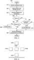
- FIGURE 5 illustrates an example process 500 of the operation of the circuit 372, according to an embodiment of the invention and with reference to FIGURE 3 . Although such an example is provided, a variety of other alternative operations may also occur consistent with this invention.
- the circuit 372 receives data from the thermostat 160.
- This data may be, for example, a 0 to 10 volt signal that was originally intended for the modulated valve component 140.
- the thermostat 160 is only watching the room temperature and is uninformed as to thermal energy in the supply and return line, the thermostat's calculation of the needed flow rate can be way off.
- the circuit 372 in receiving the data from the thermostat 160 is effectively intercepting such data for correction as appropriate.
- the data from the thermostat 160 may be analog data; however, in other configurations, the data may be supplied in other manners.
- the circuit 372 receives data from the supply line 110 and return line 150.
- This data may be flow and/or temperature data.
- this data is temperature data as the system's design is for the transfer of thermal energy to or from a room.
- the data may be communicated from any suitable sensors including, but not limited to, thermistors. In FIGURE 3 , these sensors are shown as the return line sensor 374 and the supply line sensor 376.
- the data from the return line sensor 374 and the supply line sensor 376 may be analog data; however, in other configurations, the data may be supplied in other manners.
- the data communicated from a supply line may be communicatively received from at least one sensor upstream (and in certain further configurations, another sensor downstream) of the terminal at the circuit 372.
- the circuit 372 measures the temperature differential as a basis to determine whether an overflow or underflow scenario is occurring according to decisional steps 540 and 550.
- a dynamic set point for the return line temperature can be determined based on the supply line temperature.
- the process 500 continues. However, if an overflow scenario is occurring, at decisional step 560 there is a consideration as to whether there is overriding criteria that should allow such an overflow. For example, as discussed above, if prior data shows multiple opening and closing oscillations in a short period of time, an overflow may be allowed. If overriding criteria exists, the process 500 may proceed to step 570 with a notation to allow an overflow to occur. If no overriding criteria exist, the signal to the control valve is modified appropriately and the process 500 may continue.
- step 550 if no underflow scenario exists, the process 500 continues. However, if an underflow scenario exists and there is no manner of correcting it (e.g., the valve won't open any further), an error can be recorded at step 580 and stored, for example, in storage component 372c.
- the circuit 372 provides a signal (or not) to the modulated valve component 140, which is based on the various inputs it has received as discussed infra.
- FIGURE 6 illustrates an example manner of circuits 672 communicating with one another, according to an embodiment of the invention.
- the circuit 672 generally represent the circuit 372 described in FIGURE 3 ; however, the circuits 672 may also be positioned inside a sensor such as the return line sensor 374, the supply line sensor 376, or any other sensor (e.g., pressure) that may seek to communicate information.
- the circuits 672 may be part of what is sometimes referred to as a device cloud or sensor cloud whereby the circuits can be referred to as nodes.
- a circuit 672 may only communicate with a select number or just one neighbor circuit 672. However, each respective circuit 672 may communicate all information the circuit 672 has received with its neighbors in particular embodiments. This means that, in certain embodiments, each circuit 672 should have all the information gathered by other circuits 672.
- circuit 672A may only be in communication with circuit 672B and not be in communication with circuits 672E, 672C, and 672D. However, circuit 672A receives information gathered by all the other circuits because circuit 672B, which communicates with circuits 672E, 672C, and 672D, relays information circuit 672B has received from such respective circuits. Similarly, circuit 672B also relays information circuit 672B has received from circuit 672A to circuits 672E, 672C, and 672D.
- each particular circuit 672 may have a unique identifier whereby an installer can note where the circuit 672 was installed.
- the circuits 672 may have logic onboard for self-determination of the location of the node or circuit 672 with respect to the building or other circuits 672 or node, for example as described with reference to FIGURE 7 .
- FIGURE 7 illustrates a self-determination of circuits or nodes in an ad-hoc system, according to an embodiment of the invention.
- the nodes or circuits 772 in FIGURE 7 operate in generally the same manner as the circuits 672 described in FIGURE 6 , except that that they are shown in a fluid transfer system 700, which uses the same numbering as used in FIGURE 3 .
- FIGURE 7 includes coils 130, the supply line 110, the return line 150, and the modulated valve components 140. For brevity, other components have not been shown.
- nodes or circuits 772A, 772B There are two nodes or circuits 772A, 772B that are associated with temperature sensors on the supply line. There are four nodes or circuits 772G, 772H, 7721, and 772J associated with temperature sensor on the return line 150. There are also four nodes or circuits 772C, 772D, 772E, and 772F adjacent the modulated valve components 140.
- a particular circuit or node 772 may utilize a measurement of wireless signal transmission time or wireless signal strength to determine the distance from other nodes 772.
- protocols may be utilized such that neighboring nodes all transmit a beacon signal (coupled with an identifier of the node) at the same time. The node receiving these signals can determine its location based on differences of time of arrival.
- node 772B can measure the time it takes for a beacon signal to arrive from nodes 772A, 772C, 772D, 772E (and possibly other nodes, depending on how many transmit).
- node 772B would transmit a beacon signal and the other nodes 772A, 772C, 772D, 772E (and possibly other nodes, depending on how many receive) can measure the time it takes for that beacon signal to arrive from nodes.
- wireless location determination techniques such as signal strength and angle of arrival techniques may also be utilized.
- a circuit or node 772 positioned on a pipe may also use the same time of signal travel time techniques or power of signal technique to send a signal on the pipe itself, which can be received by another circuit or node 772 on the pipe to provide an indicator as to the distance along the pipe or set of pipes a particular circuit or node 772 is from another circuit or node 772.
- node 772A may propagate a signal on supply line 110 and the time is measured by node 772D.
- the calculation of the location information may be determined by a computer (e.g., server 790), which may be outside the ad-hoc network.
- the server 790 may the same computer analyzing the various data off-loaded from the network for modeling and optimizing as appropriate.
- all of the nodes carry the information. In other embodiments, only a supervisory node carries the information.
- the decreasing temperatures along a line can confirm whether or not, for example, a circuit or node 772 could possibly be on a line.
- the circuits or nodes 772 may determine whether the thermal energy loss at the location of a particular circuit 772 or node is consistent with the ad-hoc location determination by the set of circuit 772 or node.
- the ad-hoc set of circuits 772 can self- locate and identify themselves. Assuming the location information is transmitted from node to node as described above, one can visualize a 3-D model of the thermal energy transfer system within a building - along with the potential for particular alerts. Using such a self-location technique, installers of the circuits or node need spend little time being concerned as to whether they have correctly identified the location of the installed component.
- any of a variety of networking protocols may be utilized to carry out the aforementioned communications, including those described with reference to FIGURES 6 and 7 .
- Such protocols may account for handling redundant data.
- such protocols may account for scenarios where a new circuit is brought online to replace a prior circuit in the same location to, among other things, inform the new circuit of information previously gathered by the predecessor circuit, for example, historic trends.
- a new circuit 772 may be brought online, which needs to know its location.
- a new circuit can be placed on supply line 110 in the path between circuit 772B and circuit 772C before the coil 130. In such a scenario, the new circuit 772 can initiate routines within neighboring circuit 772 for discovery and then shut down or go to sleep as appropriate after discovery has occurred.
- one of the circuits 672 or nodes may be connected to remote communication devices (e.g., servers) to allow, for a remote analysis of the entire system by a bigger computer with more processing power and potential modelling capabilities, for example, server 790 of FIGURE 7 (or review by humans). This may be carried out, for example, through one of circuits or nodes 672, 772 that is connected to an Internet connection.
- remote communication devices e.g., servers
- a troubleshooter with a handheld device that communicates with the circuit 672 can walk up to any one of the circuits 672 (e.g., circuit 672A) and gather data for all the other circuits 672 (e.g., circuits 672B, 672E, 672C, and 672D). Again, this is because each circuit 672 keeps information for all other circuits 672 in some embodiments.
- select supervisory nodes or circuits may have extra memory to store all information communicated by the nodes in the network whereas the other nodes might store a smaller subset, dumping select older data.
- a building owner may install the system and start making more intelligent decision for more efficient operations. For the example, based on input from circuits or nodes 672, 772, a precise location of the problem can quickly be reported, isolated, and fixed. Additionally, one may continuously optimize the system or undertake what is known as CONTINUOUS COMMISSION process of handling the thermal transfer system.
- the potential diagnostics based on data (including location data) gathered from the sensors is almost limitless in application.
- a building owner may additionally determine that the installation cost of the circuits or nodes 672, 772 will pay itself back with a certain number of months after installation because of a more efficient (and less costly operation).
Landscapes
- Engineering & Computer Science (AREA)
- Physics & Mathematics (AREA)
- Mechanical Engineering (AREA)
- Chemical & Material Sciences (AREA)
- Combustion & Propulsion (AREA)
- General Engineering & Computer Science (AREA)
- Remote Sensing (AREA)
- General Physics & Mathematics (AREA)
- Automation & Control Theory (AREA)
- Computer Networks & Wireless Communication (AREA)
- Arrangements For Transmission Of Measured Signals (AREA)
- Thermal Sciences (AREA)
- Mobile Radio Communication Systems (AREA)
Claims (4)
- Ad-hoc-Netzwerk für ein System (700), das ein Fluid zur Übertragung thermischer Energie verwendet, wobei das Ad-hoc-Netzwerk umfasst:eine Vielzahl von Knoten (772), wobei jeder Knoten mindestens einem Sensor (374, 376) zugeordnet ist, der zum Messen einer Temperatur des Fluids konfiguriert ist, oder einer Einheit zugeordnet ist, die zum Signalisieren eines Öffnens oder Schließens eines Ventils (140) konfiguriert ist, wobei jeder der Knoten konfiguriert ist zum:Kommunizieren mit einem oder mehreren der Vielzahl von Knoten (772);Kommunizieren von Informationen, die über einen Vorgang des Systems empfangen oder gesammelt wurden, an mindestens einen anderen Knoten;wobei mindestens einer der Knoten so konfiguriert ist, dass er alle von der Vielzahl von Knoten (772) gesammelten Informationen an einen Standort außerhalb des Ad-hoc-Netzwerks überträgt;wobei jeder der Knoten als Ortungsknoten (772B) konfiguriert ist, um automatisch mit zumindest einigen der Vielzahl von Knoten (772A, 772C, 772D, 772E) zu kommunizieren, um eine Bestimmung eines Standorts des Ortungsknotens (772B) relativ zu diesen Knoten zu ermöglichen;wobei die Bestimmung des Standorts eine Messung von einem oder mehreren von Folgendem umfasst:Zeitspannen, die ausgebreitete elektromagnetische Wellen benötigt, um sich entweder zu oder von zumindest einigen der Vielzahl von Knoten (772A, 772C, 772D, 772E) zum Ortungsknoten (772B) auszubreiten,Leistungsunterschiede bei einer Übertragung von ausgebreiteten elektromagnetischen Wellen entweder zu oder von zumindest einigen der Vielzahl von Knoten (772A, 772C, 772D, 772E) zum Ortungsknoten (772B), undZeitspannen, die Signale entlang von Rohrleitungen in einem thermischen Übertragungssystem benötigen, um sich entweder zu oder von mindestens einigen der Vielzahl von Knoten (772A, 772C, 772D, 772E) zum Ortungsknoten (772B) auszubreiten; undwobei die Bestimmung des Standorts bestätigt wird, indem überprüft wird, ob die im System bestimmte thermische Dynamik mit dem bestimmten Standort übereinstimmt.
- Ad-hoc-Netzwerk nach Anspruch 1, wobei das Ad-hoc-Netzwerk einen Server (790) umfasst, wobei die Bestimmung des Standorts durch den außerhalb des Ad-hoc-Netzwerks befindlichen Server (790) durchgeführt wird.
- Ad-hoc-Netzwerk nach Anspruch 1, wobei jeder der Knoten, der einer Einheit zugeordnet ist, die dazu konfiguriert ist, einem Ventil (140) ein Öffnen oder Schließen zu signalisieren, weiter konfiguriert ist zum:Empfangen einer Temperatur von einem Rücklauftemperatursensor (374), der zum Messen einer Temperatur des Fluids konfiguriert ist, die ein Endgerät verlässt; undErmöglichen, dass ein Signal an das Ventil (140) gesendet wird, um es basierend auf der empfangenen Temperatur zu öffnen oder zu schließen.
- Ad-hoc-Netzwerk nach Anspruch 1, wobei das Ad-hoc für das System geeignet ist, das einen Thermostat (160) verwendet, um eine einem Endgerät zugeordnete Temperatur zu regeln, und wobei jeder der Knoten, der einer Einheit zugeordnet ist, die so konfiguriert ist, dass sie einem Ventil (140) signalisiert, dass es sich öffnen oder schließen soll, weiter konfiguriert ist zum:Empfangen eines Signals vom Thermostat (160), wobei das Signal dem Ventil (140) befiehlt, sich zu öffnen oder zu schließen;Bestimmen, ob die Temperatur einen Sollwert überschreitet; undModifizieren des Signals vom Thermostat (160), wenn die Temperatur den Sollwert überschreitet.
Applications Claiming Priority (3)
| Application Number | Priority Date | Filing Date | Title |
|---|---|---|---|
| US201461955064P | 2014-03-18 | 2014-03-18 | |
| PCT/US2015/021006 WO2015142879A1 (en) | 2014-03-18 | 2015-03-17 | Retrofit smart components for use in a fluid transfer system |
| EP15765909.5A EP3120209B1 (de) | 2014-03-18 | 2015-03-17 | Intelligente nachrüstkomponenten zur verwendung in einem flüssigkeitsfördersystem |
Related Parent Applications (2)
| Application Number | Title | Priority Date | Filing Date |
|---|---|---|---|
| EP15765909.5A Division EP3120209B1 (de) | 2014-03-18 | 2015-03-17 | Intelligente nachrüstkomponenten zur verwendung in einem flüssigkeitsfördersystem |
| EP15765909.5A Division-Into EP3120209B1 (de) | 2014-03-18 | 2015-03-17 | Intelligente nachrüstkomponenten zur verwendung in einem flüssigkeitsfördersystem |
Publications (3)
| Publication Number | Publication Date |
|---|---|
| EP3686708A2 EP3686708A2 (de) | 2020-07-29 |
| EP3686708A3 EP3686708A3 (de) | 2020-10-21 |
| EP3686708B1 true EP3686708B1 (de) | 2025-05-07 |
Family
ID=54141746
Family Applications (2)
| Application Number | Title | Priority Date | Filing Date |
|---|---|---|---|
| EP20161125.8A Active EP3686708B1 (de) | 2014-03-18 | 2015-03-17 | Ad-hoc-netzwerk für ein system, das ein fluid zur übertragung thermischer energie verwendet |
| EP15765909.5A Active EP3120209B1 (de) | 2014-03-18 | 2015-03-17 | Intelligente nachrüstkomponenten zur verwendung in einem flüssigkeitsfördersystem |
Family Applications After (1)
| Application Number | Title | Priority Date | Filing Date |
|---|---|---|---|
| EP15765909.5A Active EP3120209B1 (de) | 2014-03-18 | 2015-03-17 | Intelligente nachrüstkomponenten zur verwendung in einem flüssigkeitsfördersystem |
Country Status (3)
| Country | Link |
|---|---|
| US (2) | US9933167B2 (de) |
| EP (2) | EP3686708B1 (de) |
| WO (1) | WO2015142879A1 (de) |
Families Citing this family (3)
| Publication number | Priority date | Publication date | Assignee | Title |
|---|---|---|---|---|
| DE102017123560B4 (de) | 2017-10-10 | 2024-09-12 | Eut Edelstahl Umformtechnik Gmbh | Selbstregulierende Einstellvorrichtung für ein Durchflussregelventil |
| US10425788B2 (en) * | 2018-02-08 | 2019-09-24 | King Fahd University Of Petroleum And Minerals | Equal distance different members node placement method and system |
| GB2603893B (en) * | 2021-02-09 | 2023-11-01 | Mixergy Ltd | Controller interface and system for controlling a heating system |
Family Cites Families (40)
| Publication number | Priority date | Publication date | Assignee | Title |
|---|---|---|---|---|
| US4363441A (en) | 1980-04-23 | 1982-12-14 | Emanuel Feinberg | Thermal energy usage meter for multiple unit building |
| US4388692A (en) | 1980-09-03 | 1983-06-14 | Texas Instruments Incorporated | Electronically controlled programmable digital thermostat having variable threshold hysteresis with time |
| US5383489A (en) | 1993-10-26 | 1995-01-24 | Flow Design, Inc. | Flow control valve with enhanced flow control piston |
| US5464038A (en) | 1994-08-11 | 1995-11-07 | Kruto; Donald | Fluid flow control system |
| US5904292A (en) | 1996-12-04 | 1999-05-18 | Mcintosh; Douglas S. | Modulating fluid control device |
| US6390381B1 (en) * | 2000-03-20 | 2002-05-21 | Oliver Peter Laing | Control unit and process for adjusting the heating loops in large area heating systems and to control the adjusted heating loops |
| US6276397B1 (en) | 2000-06-12 | 2001-08-21 | Flow Design, Inc. | Apparatus and method for shaping fluid flow |
| DE10108852C1 (de) | 2001-02-23 | 2002-08-29 | Techem Service Ag | Raumtemperaturregelung |
| US6523568B1 (en) | 2001-03-30 | 2003-02-25 | Flow Design, Inc. | Combination air vent/probe port and method of constructing same |
| JP2002310442A (ja) | 2001-04-10 | 2002-10-23 | Sekisui Chem Co Ltd | 床暖房システム |
| US6612504B2 (en) * | 2001-12-03 | 2003-09-02 | Applied Marine Hydronics, Inc. | Dual heat exchange mode water heating system for boats |
| US6688319B2 (en) | 2002-04-10 | 2004-02-10 | Flow Design, Inc. | Flow regulating control valve and method for regulating fluid flow |
| US20050235306A1 (en) * | 2002-09-23 | 2005-10-20 | Fima R G | Systems and methods for monitoring and controlling water consumption |
| US7347057B1 (en) * | 2003-12-12 | 2008-03-25 | Cooling Technologies, Inc. | Control of dual-heated absorption heat-transfer machines |
| US7050887B2 (en) * | 2003-12-23 | 2006-05-23 | Techstream Control Systems Inc. | Wireless sensor and control transmitter system |
| NL1025309C2 (nl) * | 2004-01-23 | 2005-07-26 | Nedap Nv | Systeem voor het onafhankelijk regelen van de temperaturen in verschillende ruimten en van de temperaturen van één of meerdere warmwaterboilers. |
| JP4910163B2 (ja) * | 2005-09-30 | 2012-04-04 | Smc株式会社 | 恒温液循環装置及び該装置における温度制御方法 |
| SE530417C2 (sv) * | 2005-11-02 | 2008-05-27 | Kimmo Yliniemi | En anordning för mätning av energiåtgång fär att värma upp tappvatten |
| SE531014C2 (sv) | 2006-06-12 | 2008-11-18 | Tour & Andersson Ab | Kägla med ställbar KVS och konstant karaktäristik |
| US8175613B2 (en) * | 2006-08-04 | 2012-05-08 | Misonimo Chi Acquisitions L.L.C. | Systems and methods for determining location of devices within a wireless network |
| US7621461B2 (en) | 2006-08-18 | 2009-11-24 | Flow Design, Inc. | System and method for regulating heat transfer on a fluid by regulating the flow of the fluid |
| US7857233B2 (en) | 2006-09-01 | 2010-12-28 | Flow Design, Inc. | Electronically based control valve with feedback to a building management system (BMS) |
| NL1032598C2 (nl) | 2006-09-29 | 2009-02-25 | Kamstrup B V | Inrichting, systeem en werkwijze voor het besturen van een verwarmingssysteem. |
| US7909262B2 (en) | 2006-12-14 | 2011-03-22 | Flow Design, Inc. | Pressure relieved thermal regulator for air conditioning application |
| US8045482B2 (en) * | 2008-02-08 | 2011-10-25 | Yahoo! Inc. | Location tracking based on proximity-based ad hoc network |
| US8843241B2 (en) * | 2008-05-20 | 2014-09-23 | LiveMeters, Inc. | Remote monitoring and control system comprising mesh and time synchronization technology |
| US20090314484A1 (en) * | 2008-06-18 | 2009-12-24 | Akz Technologies Llc | Standalone flow rate controller for controlling flow rate of cooling or heating fluid through a heat exchanger |
| PL3812870T3 (pl) * | 2008-06-26 | 2023-02-13 | Belparts Group N.V. | System sterowania przepływem |
| US9328933B2 (en) * | 2010-04-14 | 2016-05-03 | John Walsh | External thermostat fan controller |
| US20110282498A1 (en) * | 2010-05-11 | 2011-11-17 | FLS Solar Technologies, Inc. | Solar thermal data acquisition systems and methods and systems using the same |
| US9046507B2 (en) * | 2010-07-29 | 2015-06-02 | Gen-Probe Incorporated | Method, system and apparatus for incorporating capacitive proximity sensing in an automated fluid transfer procedure |
| GB201012762D0 (en) * | 2010-07-30 | 2010-09-15 | Hall Gregory | Central heating system |
| CN102607741B (zh) | 2011-01-22 | 2015-07-01 | 格兰富水泵(上海)有限公司 | 冷热量计量控制和费用分摊系统及方法 |
| EP2678621B1 (de) * | 2011-02-25 | 2018-06-13 | The Trustees Of Columbia University In The City Of New York | Automatische temperaturregelung von heizkörpern |
| US20130048114A1 (en) * | 2011-08-26 | 2013-02-28 | Optimum Energy, Llc | Controlled hydronic distribution system |
| CH706146A2 (de) * | 2012-02-29 | 2013-08-30 | Oblamatik Ag | Verfahren und System zum Temperieren von Bauteilen. |
| US9140503B2 (en) * | 2012-04-03 | 2015-09-22 | Solarlogic, Llc | Energy measurement system for fluid systems |
| US9049692B2 (en) * | 2012-04-13 | 2015-06-02 | Itron, Inc. | Hybrid access protocol for network nodes |
| US9476188B2 (en) * | 2012-06-22 | 2016-10-25 | Kohler Mira Limited | System and method for remotely disinfecting plumbing fixtures |
| US8851744B1 (en) | 2013-10-02 | 2014-10-07 | Onicon, Inc. | Calibration apparatus and method for heat transfer measurement |
-
2015
- 2015-03-17 EP EP20161125.8A patent/EP3686708B1/de active Active
- 2015-03-17 WO PCT/US2015/021006 patent/WO2015142879A1/en not_active Ceased
- 2015-03-17 EP EP15765909.5A patent/EP3120209B1/de active Active
- 2015-03-17 US US14/660,347 patent/US9933167B2/en active Active
-
2018
- 2018-02-28 US US15/908,721 patent/US10731871B2/en active Active
Also Published As
| Publication number | Publication date |
|---|---|
| EP3120209A1 (de) | 2017-01-25 |
| US20150267924A1 (en) | 2015-09-24 |
| US10731871B2 (en) | 2020-08-04 |
| EP3120209B1 (de) | 2020-05-06 |
| EP3686708A3 (de) | 2020-10-21 |
| EP3120209A4 (de) | 2018-04-25 |
| EP3686708A2 (de) | 2020-07-29 |
| WO2015142879A1 (en) | 2015-09-24 |
| US20190011135A1 (en) | 2019-01-10 |
| US9933167B2 (en) | 2018-04-03 |
Similar Documents
| Publication | Publication Date | Title |
|---|---|---|
| DK177857B1 (en) | Monitoring System | |
| CN112805528B (zh) | 传热系统的前馈流量控制 | |
| CN108476473A (zh) | 用于延长建筑物控制系统中的无线传感器的电池寿命的系统和方法 | |
| JP6033674B2 (ja) | 熱供給制御装置、熱供給システム及び熱供給制御方法 | |
| KR102363303B1 (ko) | 다중-에이전트 흐름 제어 시스템의 탈중앙집중적 계획, 스케줄링 및 제어 | |
| US10731871B2 (en) | Retrofit smart components for use in a fluid transfer system | |
| EP3732401B1 (de) | Verfahren zur steuerung eines thermischen verteilungssystems | |
| CN113883662A (zh) | 热能系统中的功率消耗的控制 | |
| EP3096118B1 (de) | Fernmessgerätablesendes kalorimeter sowie betriebsverfahren | |
| US12146666B2 (en) | Method and control server for controlling a district thermal energy distribution system | |
| EP3855079B1 (de) | Verfahren zur steuerung der wärmezufuhr in einem verteilungsnetz | |
| CN113795715B (zh) | 用于监视和控制hvac系统的方法和计算机系统 | |
| KR102455592B1 (ko) | 로컬 분배 시스템의 열 에너지 분배 그리드로부터의 열기 또는 냉기 방출을 제어하기 위한 방법 및 제어 유닛 | |
| US20230235904A1 (en) | Self-learning wireless thermostat that minimizes battery drain | |
| US11671274B2 (en) | Building with Wi-Fi mesh network | |
| WO2025083410A1 (en) | Heating control system | |
| DK202100926A1 (en) | A method and system for pressure regulation in a liquid supply network | |
| HK1213318B (en) | Monitoring system |
Legal Events
| Date | Code | Title | Description |
|---|---|---|---|
| PUAI | Public reference made under article 153(3) epc to a published international application that has entered the european phase |
Free format text: ORIGINAL CODE: 0009012 |
|
| STAA | Information on the status of an ep patent application or granted ep patent |
Free format text: STATUS: THE APPLICATION HAS BEEN PUBLISHED |
|
| AC | Divisional application: reference to earlier application |
Ref document number: 3120209 Country of ref document: EP Kind code of ref document: P |
|
| AK | Designated contracting states |
Kind code of ref document: A2 Designated state(s): AL AT BE BG CH CY CZ DE DK EE ES FI FR GB GR HR HU IE IS IT LI LT LU LV MC MK MT NL NO PL PT RO RS SE SI SK SM TR |
|
| PUAL | Search report despatched |
Free format text: ORIGINAL CODE: 0009013 |
|
| AK | Designated contracting states |
Kind code of ref document: A3 Designated state(s): AL AT BE BG CH CY CZ DE DK EE ES FI FR GB GR HR HU IE IS IT LI LT LU LV MC MK MT NL NO PL PT RO RS SE SI SK SM TR |
|
| RIC1 | Information provided on ipc code assigned before grant |
Ipc: F24D 19/10 20060101ALI20200916BHEP Ipc: G05D 23/00 20060101AFI20200916BHEP Ipc: H04Q 9/00 20060101ALI20200916BHEP Ipc: H04W 4/18 20090101ALI20200916BHEP Ipc: G05D 23/19 20060101ALI20200916BHEP |
|
| STAA | Information on the status of an ep patent application or granted ep patent |
Free format text: STATUS: REQUEST FOR EXAMINATION WAS MADE |
|
| 17P | Request for examination filed |
Effective date: 20210421 |
|
| RBV | Designated contracting states (corrected) |
Designated state(s): AL AT BE BG CH CY CZ DE DK EE ES FI FR GB GR HR HU IE IS IT LI LT LU LV MC MK MT NL NO PL PT RO RS SE SI SK SM TR |
|
| STAA | Information on the status of an ep patent application or granted ep patent |
Free format text: STATUS: EXAMINATION IS IN PROGRESS |
|
| 17Q | First examination report despatched |
Effective date: 20230316 |
|
| GRAP | Despatch of communication of intention to grant a patent |
Free format text: ORIGINAL CODE: EPIDOSNIGR1 |
|
| STAA | Information on the status of an ep patent application or granted ep patent |
Free format text: STATUS: GRANT OF PATENT IS INTENDED |
|
| RIC1 | Information provided on ipc code assigned before grant |
Ipc: F24F 11/84 20180101ALI20241017BHEP Ipc: H04W 4/18 20090101ALI20241017BHEP Ipc: H04Q 9/00 20060101ALI20241017BHEP Ipc: G05D 23/19 20060101ALI20241017BHEP Ipc: F24D 19/10 20060101ALI20241017BHEP Ipc: G05D 23/00 20060101AFI20241017BHEP |
|
| INTG | Intention to grant announced |
Effective date: 20241112 |
|
| GRAS | Grant fee paid |
Free format text: ORIGINAL CODE: EPIDOSNIGR3 |
|
| GRAA | (expected) grant |
Free format text: ORIGINAL CODE: 0009210 |
|
| STAA | Information on the status of an ep patent application or granted ep patent |
Free format text: STATUS: THE PATENT HAS BEEN GRANTED |
|
| AC | Divisional application: reference to earlier application |
Ref document number: 3120209 Country of ref document: EP Kind code of ref document: P |
|
| AK | Designated contracting states |
Kind code of ref document: B1 Designated state(s): AL AT BE BG CH CY CZ DE DK EE ES FI FR GB GR HR HU IE IS IT LI LT LU LV MC MK MT NL NO PL PT RO RS SE SI SK SM TR |
|
| REG | Reference to a national code |
Ref country code: GB Ref legal event code: FG4D |
|
| REG | Reference to a national code |
Ref country code: CH Ref legal event code: EP |
|
| REG | Reference to a national code |
Ref country code: DE Ref legal event code: R096 Ref document number: 602015091621 Country of ref document: DE |
|
| REG | Reference to a national code |
Ref country code: SE Ref legal event code: TRGR |
|
| REG | Reference to a national code |
Ref country code: IE Ref legal event code: FG4D |
|
| REG | Reference to a national code |
Ref country code: NL Ref legal event code: FP |
|
| PG25 | Lapsed in a contracting state [announced via postgrant information from national office to epo] |
Ref country code: PT Free format text: LAPSE BECAUSE OF FAILURE TO SUBMIT A TRANSLATION OF THE DESCRIPTION OR TO PAY THE FEE WITHIN THE PRESCRIBED TIME-LIMIT Effective date: 20250908 Ref country code: ES Free format text: LAPSE BECAUSE OF FAILURE TO SUBMIT A TRANSLATION OF THE DESCRIPTION OR TO PAY THE FEE WITHIN THE PRESCRIBED TIME-LIMIT Effective date: 20250507 Ref country code: FI Free format text: LAPSE BECAUSE OF FAILURE TO SUBMIT A TRANSLATION OF THE DESCRIPTION OR TO PAY THE FEE WITHIN THE PRESCRIBED TIME-LIMIT Effective date: 20250507 |
|
| REG | Reference to a national code |
Ref country code: LT Ref legal event code: MG9D |
|
| PG25 | Lapsed in a contracting state [announced via postgrant information from national office to epo] |
Ref country code: NO Free format text: LAPSE BECAUSE OF FAILURE TO SUBMIT A TRANSLATION OF THE DESCRIPTION OR TO PAY THE FEE WITHIN THE PRESCRIBED TIME-LIMIT Effective date: 20250807 Ref country code: GR Free format text: LAPSE BECAUSE OF FAILURE TO SUBMIT A TRANSLATION OF THE DESCRIPTION OR TO PAY THE FEE WITHIN THE PRESCRIBED TIME-LIMIT Effective date: 20250808 |
|
| PG25 | Lapsed in a contracting state [announced via postgrant information from national office to epo] |
Ref country code: PL Free format text: LAPSE BECAUSE OF FAILURE TO SUBMIT A TRANSLATION OF THE DESCRIPTION OR TO PAY THE FEE WITHIN THE PRESCRIBED TIME-LIMIT Effective date: 20250507 |
|
| REG | Reference to a national code |
Ref country code: AT Ref legal event code: MK05 Ref document number: 1793169 Country of ref document: AT Kind code of ref document: T Effective date: 20250507 |
|
| PG25 | Lapsed in a contracting state [announced via postgrant information from national office to epo] |
Ref country code: BG Free format text: LAPSE BECAUSE OF FAILURE TO SUBMIT A TRANSLATION OF THE DESCRIPTION OR TO PAY THE FEE WITHIN THE PRESCRIBED TIME-LIMIT Effective date: 20250507 |
|
| PG25 | Lapsed in a contracting state [announced via postgrant information from national office to epo] |
Ref country code: HR Free format text: LAPSE BECAUSE OF FAILURE TO SUBMIT A TRANSLATION OF THE DESCRIPTION OR TO PAY THE FEE WITHIN THE PRESCRIBED TIME-LIMIT Effective date: 20250507 |
|
| PG25 | Lapsed in a contracting state [announced via postgrant information from national office to epo] |
Ref country code: AT Free format text: LAPSE BECAUSE OF FAILURE TO SUBMIT A TRANSLATION OF THE DESCRIPTION OR TO PAY THE FEE WITHIN THE PRESCRIBED TIME-LIMIT Effective date: 20250507 |
|
| PG25 | Lapsed in a contracting state [announced via postgrant information from national office to epo] |
Ref country code: RS Free format text: LAPSE BECAUSE OF FAILURE TO SUBMIT A TRANSLATION OF THE DESCRIPTION OR TO PAY THE FEE WITHIN THE PRESCRIBED TIME-LIMIT Effective date: 20250807 |
|
| PG25 | Lapsed in a contracting state [announced via postgrant information from national office to epo] |
Ref country code: IS Free format text: LAPSE BECAUSE OF FAILURE TO SUBMIT A TRANSLATION OF THE DESCRIPTION OR TO PAY THE FEE WITHIN THE PRESCRIBED TIME-LIMIT Effective date: 20250907 |
|
| PG25 | Lapsed in a contracting state [announced via postgrant information from national office to epo] |
Ref country code: LV Free format text: LAPSE BECAUSE OF FAILURE TO SUBMIT A TRANSLATION OF THE DESCRIPTION OR TO PAY THE FEE WITHIN THE PRESCRIBED TIME-LIMIT Effective date: 20250507 |