EP3686560B1 - Magnetic attractive rotary button system - Google Patents
Magnetic attractive rotary button system Download PDFInfo
- Publication number
- EP3686560B1 EP3686560B1 EP19154032.7A EP19154032A EP3686560B1 EP 3686560 B1 EP3686560 B1 EP 3686560B1 EP 19154032 A EP19154032 A EP 19154032A EP 3686560 B1 EP3686560 B1 EP 3686560B1
- Authority
- EP
- European Patent Office
- Prior art keywords
- magnet
- rotary button
- sensor device
- magnetic
- magnetic field
- Prior art date
- Legal status (The legal status is an assumption and is not a legal conclusion. Google has not performed a legal analysis and makes no representation as to the accuracy of the status listed.)
- Active
Links
- 230000005291 magnetic effect Effects 0.000 title claims description 155
- 230000005294 ferromagnetic effect Effects 0.000 claims description 60
- 230000005405 multipole Effects 0.000 claims description 11
- 230000004323 axial length Effects 0.000 claims description 5
- 230000035945 sensitivity Effects 0.000 claims description 5
- 239000002184 metal Substances 0.000 description 58
- 230000008901 benefit Effects 0.000 description 9
- 230000006870 function Effects 0.000 description 9
- 239000011521 glass Substances 0.000 description 9
- 238000010586 diagram Methods 0.000 description 8
- 239000004033 plastic Substances 0.000 description 8
- 238000000034 method Methods 0.000 description 5
- 230000001419 dependent effect Effects 0.000 description 4
- 238000004140 cleaning Methods 0.000 description 3
- 230000000694 effects Effects 0.000 description 3
- 230000004907 flux Effects 0.000 description 3
- 239000000463 material Substances 0.000 description 3
- 238000011109 contamination Methods 0.000 description 2
- 239000000696 magnetic material Substances 0.000 description 2
- 239000004065 semiconductor Substances 0.000 description 2
- 238000004088 simulation Methods 0.000 description 2
- 229910001220 stainless steel Inorganic materials 0.000 description 2
- 239000010935 stainless steel Substances 0.000 description 2
- 230000005355 Hall effect Effects 0.000 description 1
- 238000004026 adhesive bonding Methods 0.000 description 1
- 230000032683 aging Effects 0.000 description 1
- 230000003321 amplification Effects 0.000 description 1
- 230000006399 behavior Effects 0.000 description 1
- 238000004364 calculation method Methods 0.000 description 1
- 239000003302 ferromagnetic material Substances 0.000 description 1
- 230000005415 magnetization Effects 0.000 description 1
- 238000004519 manufacturing process Methods 0.000 description 1
- 238000003199 nucleic acid amplification method Methods 0.000 description 1
- 239000002985 plastic film Substances 0.000 description 1
- 230000009467 reduction Effects 0.000 description 1
- 230000003068 static effect Effects 0.000 description 1
- 230000005641 tunneling Effects 0.000 description 1
Images


Classifications
-
- H—ELECTRICITY
- H01—ELECTRIC ELEMENTS
- H01H—ELECTRIC SWITCHES; RELAYS; SELECTORS; EMERGENCY PROTECTIVE DEVICES
- H01H25/00—Switches with compound movement of handle or other operating part
- H01H25/06—Operating part movable both angularly and rectilinearly, the rectilinear movement being along the axis of angular movement
-
- G—PHYSICS
- G05—CONTROLLING; REGULATING
- G05G—CONTROL DEVICES OR SYSTEMS INSOFAR AS CHARACTERISED BY MECHANICAL FEATURES ONLY
- G05G1/00—Controlling members, e.g. knobs or handles; Assemblies or arrangements thereof; Indicating position of controlling members
- G05G1/08—Controlling members for hand actuation by rotary movement, e.g. hand wheels
- G05G1/10—Details, e.g. of discs, knobs, wheels or handles
-
- G—PHYSICS
- G01—MEASURING; TESTING
- G01D—MEASURING NOT SPECIALLY ADAPTED FOR A SPECIFIC VARIABLE; ARRANGEMENTS FOR MEASURING TWO OR MORE VARIABLES NOT COVERED IN A SINGLE OTHER SUBCLASS; TARIFF METERING APPARATUS; MEASURING OR TESTING NOT OTHERWISE PROVIDED FOR
- G01D5/00—Mechanical means for transferring the output of a sensing member; Means for converting the output of a sensing member to another variable where the form or nature of the sensing member does not constrain the means for converting; Transducers not specially adapted for a specific variable
- G01D5/12—Mechanical means for transferring the output of a sensing member; Means for converting the output of a sensing member to another variable where the form or nature of the sensing member does not constrain the means for converting; Transducers not specially adapted for a specific variable using electric or magnetic means
- G01D5/14—Mechanical means for transferring the output of a sensing member; Means for converting the output of a sensing member to another variable where the form or nature of the sensing member does not constrain the means for converting; Transducers not specially adapted for a specific variable using electric or magnetic means influencing the magnitude of a current or voltage
- G01D5/142—Mechanical means for transferring the output of a sensing member; Means for converting the output of a sensing member to another variable where the form or nature of the sensing member does not constrain the means for converting; Transducers not specially adapted for a specific variable using electric or magnetic means influencing the magnitude of a current or voltage using Hall-effect devices
- G01D5/145—Mechanical means for transferring the output of a sensing member; Means for converting the output of a sensing member to another variable where the form or nature of the sensing member does not constrain the means for converting; Transducers not specially adapted for a specific variable using electric or magnetic means influencing the magnitude of a current or voltage using Hall-effect devices influenced by the relative movement between the Hall device and magnetic fields
-
- G—PHYSICS
- G01—MEASURING; TESTING
- G01R—MEASURING ELECTRIC VARIABLES; MEASURING MAGNETIC VARIABLES
- G01R33/00—Arrangements or instruments for measuring magnetic variables
- G01R33/02—Measuring direction or magnitude of magnetic fields or magnetic flux
- G01R33/06—Measuring direction or magnitude of magnetic fields or magnetic flux using galvano-magnetic devices
- G01R33/07—Hall effect devices
- G01R33/077—Vertical Hall-effect devices
-
- H—ELECTRICITY
- H01—ELECTRIC ELEMENTS
- H01H—ELECTRIC SWITCHES; RELAYS; SELECTORS; EMERGENCY PROTECTIVE DEVICES
- H01H36/00—Switches actuated by change of magnetic field or of electric field, e.g. by change of relative position of magnet and switch, by shielding
- H01H36/0006—Permanent magnet actuating reed switches
- H01H36/0013—Permanent magnet actuating reed switches characterised by the co-operation between reed switch and permanent magnet; Magnetic circuits
- H01H36/002—Actuation by moving ferromagnetic material, switch and magnet being fixed
-
- G—PHYSICS
- G01—MEASURING; TESTING
- G01D—MEASURING NOT SPECIALLY ADAPTED FOR A SPECIFIC VARIABLE; ARRANGEMENTS FOR MEASURING TWO OR MORE VARIABLES NOT COVERED IN A SINGLE OTHER SUBCLASS; TARIFF METERING APPARATUS; MEASURING OR TESTING NOT OTHERWISE PROVIDED FOR
- G01D2205/00—Indexing scheme relating to details of means for transferring or converting the output of a sensing member
- G01D2205/40—Position sensors comprising arrangements for concentrating or redirecting magnetic flux
Definitions
- the metal plate has a disk shape or a circular cross section, because such a shape does not favour certain angular positions above others.
- a circular shape is ideal for detecting any arbitrary position of the knob. (It is noted that a disk shape does not have a central opening, in contrast to a ring shape).
- the sensor device comprises at least a first vertical Hall element having a first axis of maximum sensitivity in a first direction, and a second vertical Hall element having a second axis of maximum sensitivity parallel in a second direction, the first and the second direction being parallel to said metal plate.
- the permanent magnet is an axially magnetised magnet arranged such that the axial direction of the magnet is substantially perpendicular to said rotation axis.
- the permanent magnet is a multipole disk magnet or a multipole ring magnet, magnetized in a plane substantially perpendicular to said rotation axis.
- the magnetic sensor device 130 may comprise a plurality of magnetic sensors (e.g. at least four Horizontal Hall elements, or at least two Vertical Hall elements) for measuring at least two magnetic field components (for example two in-plane magnetic field components Bx, By).
- This magnetic sensor device 130 may be configured for determining an absolute angular position ⁇ of the rotary button 120 based on said at least two measured field components.
- This embodiment offers the advantage that the angular position can be determine more accurately, over a larger range (e.g. 360°), and that it is more robust to ageing or demagnetisation of the magnet.
- buttons having an axially magnetized magnet with a cross section other than square or rectangular or circular can also be used.
- Suitable sensor devices are for example described in WO2014029885A1 , which document is incorporated herein in its entirety, especially the sections describing sensor arrangements for measuring the magnetic field at several locations and in particular directions, and the sections with formulas for calculating the angular position of a multipole magnet, more specifically for a quadrupole.
- suitable sensor devices typically comprise a plurality of sensor elements which are spaced apart, and which are oriented in predefined directions. The angular position can be calculated for example using on a arctan function of a ratio of difference signals. It is pointed out however, that the present invention is not limited only to the sensor devices described in WO2014029885A1 , and other suitable sensor devices may also be used.
- the multipole magnet 1722 is a four-pole magnet, also known as quadrupole, but the invention also works for magnets having more than four poles, for example having six or eight poles.
Landscapes
- Physics & Mathematics (AREA)
- General Physics & Mathematics (AREA)
- Condensed Matter Physics & Semiconductors (AREA)
- Engineering & Computer Science (AREA)
- Automation & Control Theory (AREA)
- Rotary Switch, Piano Key Switch, And Lever Switch (AREA)
- Transmission And Conversion Of Sensor Element Output (AREA)
- Switches With Compound Operations (AREA)
Description
- The present invention relates in general to knobs for domestic appliances, and more in particular to a rotary button system comprising a knob comprising a magnet for use in a domestic appliance (or household device).
- Domestic appliances such as for example heaters or ovens or microwave ovens often have pushbuttons or sliders or rotary buttons for allowing a user to select a particular mode of operation, or for allowing the user to select a particular setting (e.g. a power setting or a temperature setting) of the device. Such buttons are typically subject to mechanical wear, and cleaning of the device may be difficult, especially in the vicinity of the buttons.
-
CN105281732 A andUS2018066963 A1 describe control buttons and encoding methods thereof. - There is always room for improvements or alternatives.
-
Claim 1 describes a rotary button system according to the invention. - It is an object of embodiments of the present invention to provide a rotary button system for use in a domestic appliance, wherein the rotary button is easily mountable and easily removable.
- It is an object of embodiments of the present invention to provide a rotary button system for use in a domestic appliance, where the rotary button is easier to manufacture.
- It is an object of embodiments of the present invention to provide a rotary button system capable of differentiating between one out of three predefined angular positions.
- It is an object of embodiments of the present invention to provide a rotary button system capable of measuring an absolute angular position from 0° to 180°.
- It is an object of embodiments of the present invention to provide a rotary button system capable of measuring an absolute angular position from 0° to 360°.
- It is an object of embodiments of the present invention to provide a rotary button system which has fewer components, and/or is easier to assemble, or which is an alternative to existing solutions.
- These and other objects are accomplished by a rotary button system according to embodiments of the present invention.
- According to a first aspect, the present invention provides a rotary button system for use in a domestic apparatus, comprising: a ferromagnetic plate; a rotary button removably mountable at a predefined first distance from said ferromagnetic plate on a first side of said plate, and rotatable about a virtual rotation axis substantially perpendicular to said plate, and comprising a permanent magnet magnetised in a direction substantially perpendicular to said rotation axis; a magnetic sensor device mounted at a predefined second distance from said ferromagnetic plate on a second side of said plate opposite the first side; and wherein the magnetic sensor device comprises at least one magnetic sensor for measuring at least one magnetic field component, and is configured for determining an angular position of the rotary button based on said at least one field component, or wherein the magnetic sensor device comprises at least two magnetic sensors, and is configured for determining at least one magnetic field gradient, and is configured for determining an angular position of the rotary button based on said at least one magnetic field gradient.
- Preferably, said magnet is the only magnet of the rotary button system.
- This rotary button system can be used, for example, to determine an angular position of a knob of a domestic apparatus, while the knob is easily removable from the apparatus (e.g. without the use of bolts).
- It is an advantage that the knob can be held in position in a non-contact manner (more specifically, without the magnet having to directly contact the ferromagnetic plate), and without having to make an opening in the ferromagnetic plate. In this manner, cleaning of the apparatus is made easier, and the risk of contamination of an inner space of the apparatus is reduced.
- It is an advantage of this system that the button can be mounted at a predefined distance or position relative to said plate without making direct physical contact with said plate.
- It is an advantage of this system that the button can exert an attractive force on the ferromagnetic plate, and vice versa, for holding the button (with the magnet) in position.
- It is an advantage of this system that no second magnet is required for holding the button in position, e.g. located on the same side as the magnetic sensor device.
- It is common believe that a static magnetic field cannot pass beyond a ferromagnetic plate (because the ferromagnetic plate functions as a shield), or it is at least contra-intuitive.
- It is noted that a magnetic sensor device with a single magnetic sensor is not ideal, but it is sufficient to determine (or at least approximate) an angle in an 180° angular range (e.g. using a look-up table), which may be sufficient for certain domestic applications.
- In an embodiment, the magnetic sensor device comprises only a single magnetic sensor, and is configured for determining one out a three predefined angular positions.
- This can be implemented for example by measuring the magnetic field component (e.g. By), and if the measured field component has a value higher than a first predefined threshold value to decide that the knob is in a first position, and if the measured field component has a value smaller than a second predefined threshold value to decide that the knob is in a second position, and if the measured field component has a value between the first and second predefined threshold value, to decide that the knob is in a third position. The first predefined threshold value may be a positive value, and the second predefined threshold value may be a negative value.
- In an embodiment, the magnetic sensor device comprises at least two magnetic sensors for measuring at least two magnetic field components preferably in different directions, and is configured for determining an angular position of the rotary button based on said at least two magnetic field components.
- It is an advantage of this rotary button system that it allows to more accurately determine said angular position, and in a range of 360°. The at least two magnetic sensors preferably have an axis of maximum sensitivity forming an angle of about 90°.
- In an embodiment, the magnetic sensor device comprises at least four magnetic sensors for measuring at least four magnetic field components, and is configured for determining at least two magnetic field gradients in different directions, and is configured for determining an angular position of the rotary button based on said at least two magnetic field gradients.
- The four magnetic sensors are preferably organized in two pairs of sensors, the sensors of each pair being arranged in a same direction, but being spaced apart in said direction, the sensors of different pairs being oriented in different directions.
- In an embodiment, the metal plate has a substantially disk shape.
- It is an advantage if the metal plate has a disk shape or a circular cross section, because such a shape does not favour certain angular positions above others. In other words, a circular shape is ideal for detecting any arbitrary position of the knob. (It is noted that a disk shape does not have a central opening, in contrast to a ring shape).
- In an embodiment, the diameter of the disk shape is larger than 3 mm, or larger than 4 mm, or larger than 5 mm, or larger than 6 mm, or larger than 7 mm, or larger than 8 mm, or larger than 10 mm, or larger than 12 mm, or larger than 14 mm, or larger than 16 mm, or larger than 18 mm, or larger than 20 mm, or larger than 25 mm, or larger than 30 mm, or larger than 35 mm, or larger than 4 cm, or larger than 5 cm, or larger than 6 cm, or larger than 7 cm, or larger than 8 cm, or larger than 9 cm, or larger than 10 cm.
- In an embodiment, the diameter of the disk shape is a value in the range from 3 mm to 20 mm, or in the range from 5 mm to 15 mm, or from 5 mm to 10 mm.
- In an embodiment, the diameter of the disk shape is larger than 60% of a transverse dimension of the magnet, or at leat 70%, or at least 80%, or at least 90%, or at least 100% or at least 110%, or at least 120%, or at least 130%, or at least 140%, or at least 150%, or at least 175%, or at least 200%, or at least 300%, or at least 400%, or at least 500%.
- In an embodiment, the metal plate has a substantially rectangular shape.
- In an embodiment, the rectangle has an area chosen such that a perpendicular projection of the magnet on the plane of the metal plate overlaps at least for 60% with the metal plate, or at least 70%, or at least 80%, or at least 90%, or at least 100%, or at least 110%, or at least 120%, or at least 130%, or at least 140%, or at least 150%, or at least 175%, or at least 200%, or at least 300%, or at least 400%, or at least 500%.
- In an embodiment, the metal plate has a shape and size sufficiently large, such that the metal plate prevents that the magnetic sensor device and the magnet are in direct line of sight, for any angular position of the knob, when the knob is mounted to the metal plate.
- In an embodiment, the ferromagnetic plate has a thickness in the range from 0.3 to 1.0 mm, for example equal to about 0.5 mm, or equal to about 0.6 mm, or equal to about 0.7 mm, or equal to about 0.8 mm, or equal to about 0.9 mm.
- In an embodiment, the magnetic sensor device is located substantially on said rotation axis.
- It is an advantage if the sensor devices located at a very small (ideally zero) offset from said rotation axis, because this allows a more accurate angular position.
- Preferably the offset (in radial direction) between the magnetic sensor device and the rotation axis is smaller than 3 mm, or smaller than 2 mm, or smaller than 1.0 mm.
- In an embodiment, the magnetic position sensor has a plurality of magnetic sensors configured for measuring at least two two in-plane magnetic field components, preferably in different directions, and for determining said angular position based on said in-plane magnetic field components.
- Preferably the two in plane magnetic field components are oriented substantially perpendicular to each other. This allows to calculate the angular position of the magnet using for example based on an arctan or arctan2 function.
- In an embodiment, the sensor device comprises at least a first vertical Hall element having a first axis of maximum sensitivity in a first direction, and a second vertical Hall element having a second axis of maximum sensitivity parallel in a second direction, the first and the second direction being parallel to said metal plate.
- Preferably, the first and the second direction form an angle equal to about 90°, but that is not absolutely required for the invention to work, and any angle in the range from 20° to 160° would also work.
- In an embodiment, the sensor device comprises at least four horizontal Hall elements and at least one integrated magnetic concentrator.
- In case only a single integrated magnetic concentrator (IMC) is present, this IMC may have a circular shape or a "plus sign" shape or any other suitable shape. But it is also possible to provide a first pair of horizontal Hall elements with a first elongated IMC oriented in the X direction, and a second pair of horizontal Hall elements with a second elongated IMC oriented in the Y direction, preferably perpendicular to the X direction.
- In an embodiment, the permanent magnet is a diametrically magnetized disk magnet arranged substantially coaxially with said rotation axis.
- In an embodiment, the permanent magnet is a diametrically magnetized ring magnet arranged substantially coaxially with said rotation axis.
- In an embodiment, the permanent magnet is an axially magnetised magnet arranged such that the axial direction of the magnet is substantially perpendicular to said rotation axis.
- In an embodiment, the permanent magnet is a multipole disk magnet or a multipole ring magnet, magnetized in a plane substantially perpendicular to said rotation axis.
- This is illustrated for example in
FIG. 1 andFIG. 12 to FIG. 14 , but the present invention is not limited to these examples. - In an embodiment, the magnet is a diametrically magnetised disk magnet having a diameter (Dm) in the range from 4 to 14 mm, or from 4 to 10 mm.
- In an embodiment, the magnet is a multipole disk or ring magnet having a diameter in the range from 4 to 14 mm, or from 4 to 10 mm.
- In an embodiment, the magnet is an axially magnetised magnet having an axial length (Lm) in the range from 4 to 14 mm, or from 4 to 10 mm.
- In an embodiment, the second distance between the magnetic sensor device and the ferromagnetic plate is a value in the range from 0.5 to 6.5 mm, or in the range from 1.0 to 4.5 mm, or from 1.25 to 4.0 mm, for example equal to about 1.5 mm, or equal to about 2.0 mm, or equal to about 2.5 mm, or equal to about 3.0 mm, or equal to about 3.5 mm, or equal to about 4.0 mm.
- This distance can for example be created by mounting the magnet inside the knob at a non-zero offset from a bottom plane, or can for example be created by providing a glass or plastic sheet between the metal plate and the knob, or in any other suitable way.
- In an embodiment, the magnet is a diametrically magnetised disk magnet having a diameter in the range from 4 to 14 mm or an axially magnetised magnet having an axial length in the range from 4 to 14 mm; and the first distance between the ferromagnetic plate and the magnet is a value in the range from 0.5 to 1.5 mm; and the ferromagnetic plate has a thickness in the range from 0.3 to 1.0 mm; and the second distance between the ferromagnetic plate and the magnetic sensor device is a value in the range from 1.0 to 4.5 mm, and preferably the ferromagnetic plate has an area in the range from 15 mm2 to about 400 cm2.
- In an embodiment, the magnetic sensor device is further adapted for determining a presence of the rotary button at said predefined distance from the ferromagnetic plate.
- Particular and preferred aspects of the invention are set out in the accompanying independent and dependent claims. Features from the dependent claims may be combined with features of the independent claims and with features of other dependent claims as appropriate and not merely as explicitly set out in the claims. These and other aspects of the invention will be apparent from and elucidated with reference to the embodiment(s) described hereinafter.
-
-
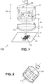
FIG. 1 shows an exemplary rotary button system according to an embodiment of the present invention in perspective view. -
FIG. 2 shows the knob and the metal plate or metal sheet of the system ofFIG. 1 . The metal plate may be part of a front panel of a domestic appliance. The knob is completely removable. -
FIG. 3 shows a variant of the rotary button system ofFIG. 1 in side view. It illustrates the relative positions of the knob, the magnet inside the knob, the metallic plate, and the sensor device.FIG. 3 also shows presumed exemplary magnetic field lines. -
FIG. 4 shows an exemplary block diagram of an angular position sensor device comprising four Horizontal Hall elements and a disk shaped IMC, as may be used in the rotary button system ofFIG. 1 or FIG. 2 . -
FIG. 5 shows an exemplary block diagram of an angular position sensor device comprising two vertical Hall elements, as may be used in the rotary button system ofFIG. 1 or FIG. 2 . -
FIG. 6 shows the arrangement ofFIG. 3 with specific dimensions. This arrangement was simulated, and the results are shown inFIG. 7 to FIG. 9 . -
FIG. 7 shows exemplary waveforms of "in-plane" magnetic field components Bx, By as can be measured by the sensor device of the system shown inFIG. 6 , as a function of the rotation angle of the knob. -
FIG. 8 shows how the signals ofFIG. 7 can be used to calculate an angle, for example using an arctan or arctan2 function. -
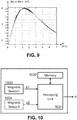
FIG. 9 shows how the signal strength of the signals ofFIG. 7 varies as a function of the distance between the metal plate and the sensor device. -
FIG. 10 shows an exemplary block diagram of a magnetic sensor device, as may be used in the rotary button system ofFIG. 1 or FIG. 2 . -
FIG. 11 shows another exemplary block diagram of a magnetic sensor device, as may be used in the rotary button system ofFIG. 1 or FIG. 2 . -
FIG. 12 shows a variant of the button shown inFIG. 1 or FIG. 2 , comprising an axially magnetized bar magnet oriented perpendicular to the rotation axis of the knob. -
FIG. 13 shows another variant of the button shown inFIG. 1 or FIG. 2 , comprising a diametrically magnetized ring magnet, having a central axis coinciding with the rotation axis of the knob. -
FIG. 14 shows another variant of the button shown inFIG. 1 or FIG. 2 , comprising an axially magnetized cylindrical magnet oriented perpendicular to the rotation axis of the knob. -
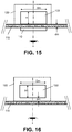
FIG. 15 shows a first example of how the distance between the metal plate and the magnet can be realised, in the example by placing a glass or plastic plate between the metal plate and the knob. -
FIG. 16 shows another example of how the distance between the metal plate and the magnet can be realised, in the example by locating the magnet at an offset from a button surface of the button. -
FIG. 17 shows another variant of the button shown inFIG. 1 or FIG. 2 , comprising a multipole disk magnet magnetized in a direction substantially perpendicular to the rotation axis of the knob. -
FIG. 18 shows a variant ofFIG. 17 , wherein theknob 1820 comprises a four-pole ring magnet. - The drawings are only schematic and are non-limiting. In the drawings, the size of some of the elements may be exaggerated and not drawn on scale for illustrative purposes. Any reference signs in the claims shall not be construed as limiting the scope. In the different drawings, the same reference signs refer to the same or analogous elements.
- The present invention will be described with respect to particular embodiments and with reference to certain drawings but the invention is not limited thereto but only by the claims. The drawings described are only schematic and are non-limiting. In the drawings, the size of some of the elements may be exaggerated and not drawn on scale for illustrative purposes. The dimensions and the relative dimensions do not correspond to actual reductions to practice of the invention.
- Furthermore, the terms first, second and the like in the description and in the claims, are used for distinguishing between similar elements and not necessarily for describing a sequence, either temporally, spatially, in ranking or in any other manner. It is to be understood that the terms so used are interchangeable under appropriate circumstances and that the embodiments of the invention described herein are capable of operation in other sequences than described or illustrated herein.
- Moreover, the terms top, under and the like in the description and the claims are used for descriptive purposes and not necessarily for describing relative positions. It is to be understood that the terms so used are interchangeable under appropriate circumstances and that the embodiments of the invention described herein are capable of operation in other orientations than described or illustrated herein.
- It is to be noticed that the term "comprising", used in the claims, should not be interpreted as being restricted to the means listed thereafter; it does not exclude other elements or steps. It is thus to be interpreted as specifying the presence of the stated features, integers, steps or components as referred to, but does not preclude the presence or addition of one or more other features, integers, steps or components, or groups thereof. Thus, the scope of the expression "a device comprising means A and B" should not be limited to devices consisting only of components A and B. It means that with respect to the present invention, the only relevant components of the device are A and B.
- Reference throughout this specification to "one embodiment" or "an embodiment" means that a particular feature, structure or characteristic described in connection with the embodiment is included in at least one embodiment of the present invention. Thus, appearances of the phrases "in one embodiment" or "in an embodiment" in various places throughout this specification are not necessarily all referring to the same embodiment, but may. Furthermore, the particular features, structures or characteristics may be combined in any suitable manner, as would be apparent to one of ordinary skill in the art from this disclosure, in one or more embodiments.
- Similarly, it should be appreciated that in the description of exemplary embodiments of the invention, various features of the invention are sometimes grouped together in a single embodiment, figure, or description thereof for the purpose of streamlining the disclosure and aiding in the understanding of one or more of the various inventive aspects. This method of disclosure, however, is not to be interpreted as reflecting an intention that the claimed invention requires more features than are expressly recited in each claim. Rather, as the following claims reflect, inventive aspects lie in less than all features of a single foregoing disclosed embodiment. Thus, the claims following the detailed description are hereby expressly incorporated into this detailed description, with each claim standing on its own as a separate embodiment of this invention.
- Furthermore, while some embodiments described herein include some but not other features included in other embodiments, combinations of features of different embodiments are meant to be within the scope of the invention, and form different embodiments, as would be understood by those in the art. For example, in the following claims, any of the claimed embodiments can be used in any combination.
- In the description provided herein, numerous specific details are set forth. However, it is understood that embodiments of the invention may be practiced without these specific details. In other instances, well-known methods, structures and techniques have not been shown in detail in order not to obscure an understanding of this description.
- In this document, the term "metal plate" or "metal sheet" are used as synonyms. In the context of the present invention, the metal plate is a "ferromagnetic plate".
- In this document, the term "magnet" or "permanent magnet" mean the same.
- When reference is made to "transverse dimension" of the magnet, what is meant is a "diameter" of a disk shaped or ring shaped magnet, or an "axial length" of an axially magnetized magnet, as illustrated for example in
FIG. 12 to FIG. 14 . - The term "magnetic sensor" as used herein may refer to one or more sensor elements capable of measuring one or more magnetic effects, such as the Hall effect, or magnetoresistive (MR) effects. Non-limiting examples for magnetoresistive effects include GMR (giant magnetoresistance), CMR (colossal magnetoresistance), AMR (anisotropic magnetoresistance) or TMR (tunnelling magnetoresistance). Depending on the context, the term "magnetic sensor" may refer to a single magnetic sensitive element (e.g. a Horizontal Hall element or a Vertical Hall element), or to a group of magnetic elements (e.g. arranged in a Wheatstone bridge, or to a group of at least two Hall sensor elements connected in parallel), or to a sub-circuit further comprising one or more of: a biasing circuit, a readout circuit, an amplifier, an Analog-to-Digital converter, etc.
- The present invention relates to knobs for domestic appliances, more in particular for kitchen appliances, for example to a knob for an oven, or a knob for a microwave oven, or the like, and to a subsystem capable of determining an angular position of such a knob. The knob of the present invention does not contain a sliding metal contact (in contrast to for example potentiometers).
- The present invention provides a rotary button system for use in a domestic apparatus, e.g. a kitchen appliance. The rotary button system comprises: a ferromagnetic plate or a ferromagnetic sheet, a button, and a magnetic sensor device. The button is removably mountable at a predefined first distance from said ferromagnetic plate on a first side of said plate (e.g. at a front side of a front panel of the kitchen appliance). The button is rotatable about a virtual rotation axis substantially perpendicular to said plate. The button comprises a permanent magnet (typically encapsulated in the button). The magnet is magnetised in a direction substantially perpendicular to said axis, or stated in other words, when the button is mounted to said plate, the magnet is magnetised in a direction substantially parallel to the ferromagnetic plate. The resulting magnetic field may have a topology as illustrated in
FIG. 3 , but the present invention is not limited to this particular example. The magnetic sensor device is mounted at a predefined second distance from said ferromagnetic plate, on a second side of said plate opposite the first side (e.g. on the back side of said front panel). The magnetic sensor device may comprise at least one magnetic sensor for measuring at least one magnetic field component, preferably an in-plane field component (e.g. a field component Bx or By parallel to the semiconductor plane), and may be configured for determining an angular position of the rotary button based on said at least one field component. The magnetic sensor device may comprise at least two magnetic sensors for determining at least one magnetic field gradient (e.g. Bx/dx or dBy/dy), and may be configured for determining an angular position of the rotary button based on said at least one magnetic field gradient. - This combination of features provides the effect that the permanent magnet and the ferromagnetic plate attract each other without the need for an additional magnet, in contrast to the system described in
CN105281732A , where two axially magnetized magnets are arranged on opposite sides of a glass plate such that the axial direction is perpendicular to the glass plate. - But besides the attractive force between the magnet and the ferromagnetic plate, the magnetic field created by the permanent magnet can surprisingly also be sensed by the magnetic sensor, even though the sensor is located on the opposite side of the ferromagnetic plate, or "behind" the ferromagnetic plate. This is far from trivial, because there is a common believe that ferromagnetic material shields or blocks a magnetic field. In addition, it also counter-intuitive to orient a magnet such that the magnetisation is parallel to the plate, because intuitively one would expect that such field lines will not penetrate through the metal plate, and thus cannot be sensed on the other side of the metal plate. Intuitively one would expect that the magnetic flux is attracted by the ferromagnetic plate acting like a shield, and one would expect therefore that the magnetic field is substantially zero "behind" the ferromagnetic plate. Yet, the inventors surprisingly found that it is very well possible to measure a magnetic field at this location.
- Or stated in other words, the inventors surprisingly found (1) that it is possible to hold the knob with the magnet in place by means of a ferromagnetic plate without needing a second magnet, (2) that the magnet is attracted by the metal plate, even if the magnet is magnetized in a direction parallel to the metallic plate, and (3) that it is possible to measure a magnetic field corresponding to the angular position of the magnet, even if the magnet is magnetised in a direction parallel to the plate, and even if the magnetic sensor is located "behind" the ferromagnetic plate.
- The present invention is at least partially based on these insights, which are not known in combination in the prior art.
- Referring now to the figures.
-
FIG. 1 shows an exemplaryrotary button system 100 in perspective view. Thisrotary button system 100 may be part of a domestic apparatus. The button system comprises aferromagnetic plate 110, and abutton 120 removably mountable from said plate. Thebutton 120 is rotatable about avirtual rotation axis 105 substantially perpendicular to saidplate 110. The button comprises apermanent magnet 122 magnetised in a direction perpendicular to saidrotation axis 105. In the example ofFIG. 1 , thepermanent magnet 122 is a diametrically magnetized disk magnet, but other magnets may also be used (see e.g.FIG 14 andFIG. 15 ). Themagnet 122 is located at a predefined first distance "dm" from saidferromagnetic plate 110 on a first side of said plate (in the example on the top side). - The
rotary button system 100 further comprises amagnetic sensor device 130 mounted at a predefined second distance "ds" from saidferromagnetic plate 110 on a second side of said plate opposite the first side, in the example ofFIG. 1 at the bottom side of the plate. - The
magnetic sensor device 130 comprises at least one magnetic sensor (e.g. a single vertical Hall element), and is configured for determining an absolute angular position α of therotary button 120 based on said measured field component, or for determining a most likely angular position selected from a limited set of predefined angular positions. The limited set may consist of only two or only three or only four or only five predefined angular positions. - Alternatively, the
magnetic sensor device 130 may comprise a plurality of magnetic sensors (e.g. at least four Horizontal Hall elements, or at least two Vertical Hall elements) for measuring at least two magnetic field components (for example two in-plane magnetic field components Bx, By). Thismagnetic sensor device 130 may be configured for determining an absolute angular position α of therotary button 120 based on said at least two measured field components. This embodiment offers the advantage that the angular position can be determine more accurately, over a larger range (e.g. 360°), and that it is more robust to ageing or demagnetisation of the magnet. - In the example of
FIG. 1 , themagnet 122 and themagnetic sensor device 130 cannot "see" each other directly (no direct "line of sight"), because theferromagnetic plate 110 is located between themagnetic position sensor 130 and thebutton 120. As illustrated inFIG. 3 , this does not necessary mean that the metal plate size needs to be larger than a perpendicular projection of the magnet, but it may be slightly smaller (as indicated by the conical shape), depending on the distances "dm" and "ds". - In some embodiments, the size of the metal plate is at least larger than the perpendicular projection of the magnet. This has a positive influence on the attractive force.
- In the example of
FIG. 1 , theknob 121 has a cylindrical shape with an outer diameter "Dk" substantially equal to the diameter Dp of themetal plate 110, but that is not required for the present invention to work. In fact, the dimensions of the knob have no significant influence on the working of the system, except for the weight of the knob. The attractive force needs to be sufficiently large to hold the knob. For a given knob, the skilled person can easily find a suitable magnet (e.g. by trial and error). - The diameter Dm of the
disk magnet 122 is preferably smaller than or equal to the diameter Dp of the ferromagnetic plate. This has the advantage that the entire bottom side of themagnet 122 is facing a portion of the ferromagnetic plate. - The
magnetic sensor device 130 is preferably a packaged semiconductor device. In the example ofFIG. 1 , the package has 8 pins, but of course, another package could also be used. The magnetic sensor device may be soldered on a printed circuit board 131 (PCB). The PCB may contain also other components (not shown). - In some embodiments, the knob can be rotated over 360°. While not shown, the knob may have a position indicator, and the domestic appliance may have indications corresponding to particular modes or settings (e.g. operation modes of a microwave oven, and/or temperature settings, or the like).
-
FIG. 2 shows theknob 120 and themetal plate 110 or metal sheet of the system ofFIG. 1 . At least the knob is visible to the user. The metal plate may be visible, or may be hidden behind another plate, e.g. a glass plate or a plastic plate, or a plate made of another suitable material. As can be seen, the button is not mounted on a physical axis which extends from the metal plate, but is held in place by the mutual attraction force between the magnet (inside the button) and the metal plate. The user can easily mount the button by bringing the button in the vicinity of the plate, and can easily remove the button by exerting a force larger than the attractive force. Such a mounting does not suffer from mechanical wear due to a metal to metal contact, and allows easy cleaning. In addition, since no opening needs to be made in the front panel and/or in the metal plate, contamination can be avoided. -
FIG. 3 shows arotary button system 300 in side view, which is a slight variant of therotary button system 100 ofFIG. 1 . The main difference is that themetal plate 310 ofFIG. 3 has a slightly larger diameter Dp than themetal plate 110 ofFIG. 1 . The plate thickness Tp is exaggerated for illustrate purposes (to show magnetic flux lines). In reality the plate thickness is typically only about 0.3 to 1.0 mm, or only 0.3 to 0.8 mm, or only 0.4 to 0.6 mm, e.g. equal to about 0.5 mm. -
FIG. 3 illustrates the relative position of theknob 120, themagnet 122 inside the knob, themetal plate 310, and thesensor device 130. - While the inventors do not wish to be bound by any theory,
FIG. 3 also shows exemplary magnetic field lines which may be present in this rotary button system, and which may help to better understand the underlying principles of the present invention. - In close vicinity of the
metal plate 310, the magnetic field lines are substantially perpendicular to the metal plate. The magnitude of the attractive force between themagnet 122 and themetal plate 310 is mainly dependent on the distance "dm" of the gap between the magnet and the metal plate. As already indicated above, this gap may be partially or completely filled with air, or with glass or a plastic material, e.g. a non-magnetic material. - As for the magnetic field on the other side of the ferromagnetic plate, actually two phenomena may be observed:
- (i) for relatively small ferromagnetic plates, the plate seems to act as a concentrator, it draws the magnetic flux in its direction, and almost no magnetic field lines are closing above the magnet. However, as the plate is relatively thin, it saturates at some points and the magnetic field lines go around the plate and close also below the plate at the IC location, where the magnetic field can be measured;
- (ii) for relatively large ferromagnetic plates (not shown in
FIG. 3 ), the ferromagnetic plate can be magnetised, and can carry a magnetization that is sensed by themagnetic sensor device 130. - In both cases, the angular position of the knob is directly related to the orientation of the magnetic field lines, thus by measuring the magnetic field, the angular position of the knob can be determined. For completeness, it is pointed out that, for a given magnet, the skilled person can easily find suitable ferromagnetic plate dimensions, for example by trial and error.
-
FIG. 4 shows an exemplary block diagram of an angularposition sensor device 430 comprising four Horizontal Hall elements HH1-HH4 and a disk shaped integrated magnetic concentrator 435 (abbreviated as IMC), as may be used in the rotary button system ofFIG. 1 and FIG. 2 . Thismagnetic sensor device 430 is adapted for measuring two in-plane magnetic field components Bx and By. This sensor device comprises two pairs of horizontal Hall elements and a disk-shaped IMC. These sensor elements may be readout by the processing circuit shown inFIG. 11 , which may be comprised in themagnetic sensor device 430. - In a variant of
FIG. 4 , the angularposition sensor device 430 comprises only two horizontal Hall elements, for example only HH1 and HH2, or only HH3 and HH4, and the IMC may have a rectangular shape. This allows to measure only one magnetic field component, e.g. By or Bx but not both. But a single magnetic sensor may be sufficient for some applications, because it allows to measure an angular position in a 180° range (e.g. by comparing the measured value with a predefined table of values, each corresponding to a predefined angular position). - Other variants are also possible.
-
FIG. 5 shows an exemplary block diagram of another angularposition sensor device 530 comprising two vertical Hall elements VH1, VH2, as may be used in the rotary button system ofFIG. 1 andFIG. 3 . Thismagnetic sensor device 530 is adapted for measuring two in-plane magnetic field components Bx and By. These sensor elements may be readout by the processing circuit shown inFIG. 10 , which may be comprised in themagnetic sensor device 530. - It is noted however that the present invention is not limited to sensor devices comprising horizontal Hall elements or vertical Hall elements, and other magnetic sensor elements may also be used, for example based on a magnetoresisitve sensor (e.g. a Wheatstone bridge of anisotropic magnetoresistive (AMR) or giant magnetoresistive (GMR) or tunneling magneto-resistive (TMR) sensors.
- In a variant of
FIG. 5 , the angular position sensor device only comprises a single magnetic sensor, for example only the vertical Hall element VH1, or only the vertical Hall element VH2. -
FIG. 6 shows the arrangement ofFIG. 3 with specific dimensions. This arrangement was simulated, and the results are known inFIG. 7 to FIG. 9 . In this example, themagnet 122 is a diametrically magnetized disk magnet having a diameter Dm= 6 mm, and a height H= 3 mm, and a remanent magnetic field Br=1T. The distance between themagnet 122 and the metal plate is 1.0 mm. (in the simulation this distance is an airgap, but in practice, this space may be fully or partially filled for example with non-magnetic material, e.g. glass or a plastic material). The ferromagnetic plate may be Stainless steel, for example stainless steel 405. The diameter Dm of the metal plate may be 6.0 mm, and the thickness Tp equals 0.5 mm. The distance ds between thesensor device 130 and the metal plate is 2.0 mm in this example (but as will be illustrated inFIG. 9 , this distance is not critical for the invention to work). -
FIG. 7 to FIG. 9 show simulation results for the exemplary embodiment depicted inFIG. 6 . -
FIG. 7 shows exemplary waveforms of "in-plane" magnetic field components Bx, By as can be measured by the sensor device of the system shown inFIG. 6 , as a function of the rotation angle α of theknob 120. As can be seen, these signals behave like a sine and a cosine signal. -
FIG. 8 shows how the signals ofFIG. 7 can be used to calculate the angle α, using for example an arctan or an arctan2 function, or a look-up table, or in any other suitable manner. -
FIG. 9 shows how the signal strength of the signals Bx, By ofFIG. 7 varies as a function of the distance "ds" between themetal plate 110 and thesensor device 130. It came as a surprise that the signals reach a maximum amplitude of about 8 mT at a distance of about 2 mm "behind the metal plate". Such a signal is more than adequate to calculate the angular position of the knob. - This plot also shows that the rotary button system as presented herein is relatively insensitive to offset in the axial direction, since the signal only degrades marginally if the distance ds varies in the range from about 1.0 to 4.5 mm, especially when at last two components are measured, in which case the absolute value is not important, but the ratio of the two magnetic field components.
- Tests have shown that the magnitude of the measured magnetic field component(s) is also quite insensitive to offset from said rotation axis (in a radial direction), but the angle calculation based on two magnetic field components may result in a noticeable angular error at sensor level. However, even a relatively large angular error (for example +/- 10°) may be completely acceptable for a domestic appliance configured to detect the actual button position in for example only three or only four predefined positions (e.g. corresponding to three or four modes of operation of the device).
- In some embodiments, the
magnetic sensor device 130 is further adapted for determining a presence of the button at said predefined distance from the ferromagnetic plate, or stated in other words, to detect whether the knob is mounted to the metal plate or not. This can be implemented for example by measuring at least two magnetic field components (preferably orthogonal components), and by determining whether at least one of these measured field components has a value larger than a predefined threshold. In the example ofFIG. 9 , the threshold value may for example be chosen as a value in the range from 1 to 3 mT. And if this condition is satisfied, it is decided that the button is present. And if the condition is not satisfied, it is decided that the button is not present. - In a variant of this method, where at least two magnetic sensors are arranged in quadrature, a sum of the squares of the measured field component values may be compared to a predefined threshold.
-
FIG. 10 shows an electrical block-diagram of a circuit that can be used in the angularposition sensor device 130, for example further comprising one or two vertical Hall elements VH1, VH2 as shown inFIG. 5 . - The
processing unit 1031 may be adapted for determining the angular position in any known manner, for example in case both sensors are present, using the formula: α = arctan2(s2, s1), where s1 is the value provided by the first magnetic sensor 1033 (or a value derived therefrom, e.g. after amplification), and s2 is the value provided by the second magnetic sensor 1034 (or a value derived therefrom). - The
processing unit 1031 may comprise a digital processor comprising or connected to anon-volatile memory 1032 storing executable instructions and/or a look-up table or other values. Theprocessing unit 1031 may provide the result as an analog signal, or as a digital signal, for example via a data interface, for example a serial bus interface (e.g. using the I2C protocol, or using RS232 protocol, or any other suitable protocol). Angular position sensor devices are known in the art, and therefore need not be described in more detail here. They are not the main focus of the present invention. -
FIG. 11 shows an electrical block-diagram of a circuit that can be used in the angularposition sensor device 130, for example further comprising two or four of the horizontal Hall elements HH1 to HH4 shown inFIG. 4 . Theprocessing unit 1131 may be adapted for determining the angular position in any known manner, for example using the set of formulas: diff1 = HH2-HH1, diff2=HH4-HH3, α = arctan2(diff2, diff1). This circuit can be seen as a variant of the circuitFIG. 10 , and may likewise contain a digital processor and/or a non-volatile memory, and/or an analog or a digital serial interface. -
FIG. 12 to FIG. 14 show a few exemplary buttons and magnets comprised therein, as can be used in arotary button system 100 ofFIG. 1 and therotary button system 300 ofFIG. 3 . -
FIG. 12 shows abutton 1220 comprising a single axially magnetizedbar magnet 1222 where the axial direction of the magnet is oriented substantially perpendicular to the rotation axis of the knob 1220 (thus during use, substantially parallel to the metal plate 110). -
FIG. 13 shows another variant of the button shown inFIG. 1 , comprising a diametrically magnetized ring magnet, having a central axis coinciding with the rotation axis of the knob. -
FIG. 14 shows abutton 1420 which can be considered to be yet another variant of thebutton 120 shown inFIG. 1 . Thebutton 1420 comprises a single axially magnetizedcylindrical magnet 1422 where the axial direction of the magnet is oriented substantially perpendicular to the rotation axis of the knob 1420 (thus during use, substantially parallel to the metal plate 110). - The behaviour of a rotary knob system comprising the
knob 1220 ofFIG. 12 or theknob 1420 ofFIG. 14 is expected to be very similar as far as the angular position is concerned, but the attractive force between the metal plate and thecylindrical magnet 1422 is expected to be lower than for the bar magnet 1222 (for a same distance between the magnet and the metal plate, because of the rounding. - From these examples, it shall be clear that rotary buttons having an axially magnetized magnet with a cross section other than square or rectangular or circular can also be used.
-
FIG. 15 and FIG. 16 show two examples of how the distance between the metal plate and the magnet can be realised, but the present invention is not limited to these examples. -
FIG. 15 shows a first example of how the distance "dm" between the metal plate and the magnet can be realised, in the example by placing a glass orplastic plate 115 between themetal plate 110 and theknob 120. -
FIG. 16 shows another example of how the distance "dm" between themetal plate 110 and themagnet 122 can be realised, in the example by locating themagnet 122 at an offset from a button surface of thebutton 120, for example by gluing or overmolding. - A combination of the principles of
FIG. 15 (using a glass or plastic plate) andFIG. 16 (locating the magnet at an offset position) is also possible. - Other ways of providing the distance between the metal plate and the magnet are also contemplated, for example by a plastic plate with grooves and/or protrusions (not shown).
-
FIG. 17 shows another variant of thebutton 1720 shown inFIG. 1 or FIG. 2 , comprising amultipole disk magnet 1722 magnetized in a direction substantially perpendicular to therotation axis 1705 of theknob 1720. Such a magnet is known per se in the art, and sensor devices (not shown inFIG. 17 , but seeFIG. 1 ) for determining an angular position using such a magnet are also known in the art, but non in combination with a metal plate as described in this document. Suitable sensor devices are for example described inWO2014029885A1 , which document is incorporated herein in its entirety, especially the sections describing sensor arrangements for measuring the magnetic field at several locations and in particular directions, and the sections with formulas for calculating the angular position of a multipole magnet, more specifically for a quadrupole. In short, suitable sensor devices typically comprise a plurality of sensor elements which are spaced apart, and which are oriented in predefined directions. The angular position can be calculated for example using on a arctan function of a ratio of difference signals. It is pointed out however, that the present invention is not limited only to the sensor devices described inWO2014029885A1 , and other suitable sensor devices may also be used. Themultipole magnet 1722 is a four-pole magnet, also known as quadrupole, but the invention also works for magnets having more than four poles, for example having six or eight poles. -
FIG. 18 shows a variant ofFIG. 17 , wherein theknob 1820 comprises a four-pole ring magnet. - In yet another variant (not shown) of
FIG. 17 and FIG. 18 , the knob comprises a magnetic structure as described inEP3321638 (A1), having magnetic field components with different periodicities, for example the combination of a quadrupole and a dipole. This allows for very accurate positioning in combination with a 360° angular range. The documentEP3321638A1 is also incorporated herein by reference in its entirety. A rotary button system comprising such a knob would comprise a suitable sensor device, for example as described inEP3321638A1 , capable of measuring magnetic field components and of calculating field gradients, and configured for determining the angular position based thereon. - While individual features are explained in different drawings and different embodiments of the present invention, it is contemplated that features of different embodiments can be combined, as would be obvious to the skilled person, when reading this document.
-
- 100, 300
- rotary button system
- 105, 1205, 1305, 1405
- rotational axis
- 110, 310
- ferromagnetic plate
- 115
- front panel
- 120, 1220, 1320, 1420
- button
- 121
- button enclosure (e.g. plastic)
- 122, 1222, 1322, 1422
- permanent magnet
- 131
- printed circuit board
- HH1-HH4
- Horizontal Hall element
- VH1, VH2
- Vertical Hall element
- s1-s4
- signal1 - signal4
- Bx, By
- in plane magnetic field components
- Dm
- diameter of disk magnet or ring magnet
- Lm
- length of bar magnet or cylindrical magnet
- dm
- distance between permanent magnet and ferromagnetic plate
- ds
- distance between ferromagnetic plate and sensor device
- Tp
- thickness of ferromagnetic plate
- N / S
- North / South pole
- Br
- remanent magnetic field
Claims (15)
- A rotary button system (100) for use in a domestic apparatus, comprising:- a ferromagnetic plate (110);- a rotary button (120) removably mountable at a predefined first distance (dm) from said ferromagnetic plate (110) on a first side of said plate, and rotatable about a virtual rotation axis (105) substantially perpendicular to said plate, and comprising a permanent magnet (122) magnetised in a direction (X, Y) substantially perpendicular to said rotation axis (105);- a magnetic sensor device (130) mounted at a predefined second distance (ds) from said ferromagnetic plate (110) on a second side of said plate opposite the first side;- and wherein the magnetic sensor device (130) comprises at least one magnetic sensor for measuring at least one magnetic field component (By) and is configured for determining an angular position (α) of the rotary button (120) based on said at least one magnetic field component (By), and/or
wherein the magnetic sensor device (130) comprises at least two magnetic sensors, and is configured for determining at least one magnetic field gradient (dBx/dx), and is configured for determining an angular position (α) of the rotary button (120) based on said at least one magnetic field gradient. - The rotary button system (100) according to claim 1, wherein the magnetic sensor device comprises at least two magnetic sensors (HH1-HH4; VH1,VH2) for measuring at least two magnetic field components (Bx, By) in different directions (X,Y), and is configured for determining an angular position (α) of the rotary button (120) based on said at least two magnetic field components (Bx, By).
- A rotary button system (100) according to claim 1 or 2,
wherein the magnetic sensor device (130) comprises at least four magnetic sensors for measuring at least four magnetic field components, and is configured for determining at least two magnetic field gradients (dBx/dx, dBy/dy) in different directions (X,Y), and is configured for determining an angular position (α) of the rotary button (120) based on said at least two magnetic field gradients. - The rotary button system (100) according to any of the previous claims, wherein the ferromagnetic plate (110) has a disk shape.
- The rotary button system (100) according to any of the previous claims, wherein the ferromagnetic plate (110) has a rectangular shape.
- The rotary button system (100) according to any of the previous, wherein the ferromagnetic plate has a thickness (Tp) in the range from 0.3 to 1.0 mm.
- The rotary button system (100) according to any of the previous claims,
wherein the magnetic sensor device (130) is located substantially on said rotation axis (105). - The rotary button system (100) according to any of the previous claims,
wherein the magnetic sensor device (130) has a plurality of magnetic sensors (HH1-HH4; VH1,VH2) configured for measuring at least two in-plane magnetic field components (Bx, By) in different directions (X,Y), and for determining said angular position (α) based on said in-plane magnetic field components (Bx, By). - The rotary button system (100) according to any of the previous claims,
wherein the magnetic sensor device (130) comprises at least a first vertical Hall element (VH1) having a first axis of maximum sensitivity in a first direction (X), and a second vertical Hall element (VH2) having a second axis of maximum sensitivity parallel in a second direction (Y), the first and the second direction being substantially parallel to said ferromagnetic plate (110). - The rotary button system (100) according to any of the previous claims,
wherein the magnetic sensor device (130) comprises at least four horizontal Hall elements (HH1-HH4) and at least one integrated magnetic concentrator (510). - The rotary button system (100) according to any of the previous claims,
wherein the permanent magnet (122; 1222; 1322; 1422) is one of the following:- a diametrically magnetized disk magnet (122) arranged substantially coaxially with said rotation axis (105);- a diametrically magnetized ring magnet (1322) arranged substantially coaxially with said rotation axis (1305);- an axially magnetised magnet (1422) arranged such that the axial direction of the magnet is substantially perpendicular to said rotation axis (1405);- a multipole disk magnet (1722) or a multipole ring magnet, magnetized in a plane substantially perpendicular to said rotation axis (105). - The rotary button system (100) according to any of the previous claims,
wherein the magnet (122) is a diametrically magnetised disk magnet having a diameter (Dm) in the range from 4 to 14 mm;
or wherein the magnet (122) is a multipole ring magnet or a multipole disk magnet (1722) having a diameter (Dm) in the range from 4 to 14 mm;
or wherein the magnet (122) is a axially magnetised magnet having an axial length (Lm) in the range from 4 to 14 mm. - The rotary button system (100) according to any of the previous claims, wherein the second distance (ds) between the magnetic sensor device (130) and the ferromagnetic plate (110) is a value in the range from 0.5 to 6.5 mm.
- The rotary button system (100) according to any of the previous claims,
wherein the magnet (122) is a diametrically magnetised disk magnet having a diameter (Dm) in the range from 4 to 14 mm, or an axially magnetised magnet having an axial length (Lm) in the range from 4 to 14 mm;
and wherein the first distance (dm) between the ferromagnetic plate (110) and the magnet (122) is a value in the range from 0.5 to 1.5 mm;
and wherein the ferromagnetic plate (110) has a thickness (Tp) in the range from 0.3 to 1.0 mm;
and wherein the second distance (ds) between the ferromagnetic plate (110) and the magnetic sensor device (130) is a value in the range from 1.0 to 4.5 mm. - The rotary button system (100) according to any of the previous claims,- wherein the magnetic sensor device (130) comprises at least one magnetic sensor for measuring said at least one magnetic field component, and is further configured for determining a presence of the button at said predefined distance from the ferromagnetic plate by comparing a magnitude of said at least one magnetic field component with a predefined threshold;
or wherein the magnetic sensor device (130) comprises at least two magnetic sensors, and is further configured for determining a presence of the button at said predefined distance from the ferromagnetic plate by testing whether at least one of the magnetic field components provided by these sensors is larger than a predefined threshold;
or wherein the magnetic sensor device (130) comprises at least two magnetic sensors arranged in quadrature, and is further configured for determining a presence of the button at said predefined distance from the ferromagnetic plate by comparing a sum of squares of the magnetic field components provided by these sensors with a predefined threshold.
Priority Applications (3)
| Application Number | Priority Date | Filing Date | Title |
|---|---|---|---|
| EP19154032.7A EP3686560B1 (en) | 2019-01-28 | 2019-01-28 | Magnetic attractive rotary button system |
| CN202010048008.0A CN111488030B (en) | 2019-01-28 | 2020-01-16 | Magnetically attracted rotary button system |
| US16/745,972 US11257643B2 (en) | 2019-01-28 | 2020-01-17 | Magnetic attractive rotary button system |
Applications Claiming Priority (1)
| Application Number | Priority Date | Filing Date | Title |
|---|---|---|---|
| EP19154032.7A EP3686560B1 (en) | 2019-01-28 | 2019-01-28 | Magnetic attractive rotary button system |
Publications (2)
| Publication Number | Publication Date |
|---|---|
| EP3686560A1 EP3686560A1 (en) | 2020-07-29 |
| EP3686560B1 true EP3686560B1 (en) | 2021-07-14 |
Family
ID=65241189
Family Applications (1)
| Application Number | Title | Priority Date | Filing Date |
|---|---|---|---|
| EP19154032.7A Active EP3686560B1 (en) | 2019-01-28 | 2019-01-28 | Magnetic attractive rotary button system |
Country Status (3)
| Country | Link |
|---|---|
| US (1) | US11257643B2 (en) |
| EP (1) | EP3686560B1 (en) |
| CN (1) | CN111488030B (en) |
Families Citing this family (3)
| Publication number | Priority date | Publication date | Assignee | Title |
|---|---|---|---|---|
| GB2540599B (en) * | 2015-07-22 | 2021-04-14 | Cmr Surgical Ltd | Rotary encoder. |
| EP3875915B1 (en) * | 2020-03-06 | 2023-07-19 | Melexis Technologies SA | Device, system and method for determining a position of a magnet |
| EP4105768B1 (en) * | 2021-06-18 | 2024-03-06 | Melexis Technologies SA | Device and method for determining an orientation of a magnet, and a joystick |
Family Cites Families (17)
| Publication number | Priority date | Publication date | Assignee | Title |
|---|---|---|---|---|
| JPH09508214A (en) * | 1994-11-22 | 1997-08-19 | ローベルト ボツシユ ゲゼルシヤフト ミツト ベシユレンクテル ハフツング | Non-contact rotation angle detection device for rotatable members |
| US6556005B1 (en) * | 2000-01-27 | 2003-04-29 | Goodrich Avionics Systems, Inc. | Magnetic encoder apparatus capable of resolving axial and rotational displacements |
| EP1610095B1 (en) * | 2004-06-21 | 2016-08-10 | Baumer Electric AG | Rotation detector for determining the absolute angular position of a shaft |
| US8901921B2 (en) * | 2009-11-25 | 2014-12-02 | Infineon Technologies Ag | Angle measurement system for determining an angular position of a rotating shaft |
| GB2505226A (en) | 2012-08-23 | 2014-02-26 | Melexis Technologies Nv | Arrangement, method and sensor for measuring an absolute angular position using a multi-pole magnet |
| CN103591969B (en) * | 2012-08-28 | 2016-01-20 | 王嘉 | There is the waterproof coding device of built-in lifting magnet |
| DE102013219017A1 (en) * | 2012-12-20 | 2014-06-26 | Continental Teves Ag & Co. Ohg | Sensor for outputting an electrical signal |
| US9671214B2 (en) * | 2013-07-17 | 2017-06-06 | Infineon Technologies Ag | Discrete magnetic angle sensor device, a magnetic angle sensor arrangement, a method for generating an angle signal and a method for providing a sensor signal |
| US10024690B2 (en) * | 2015-04-14 | 2018-07-17 | Texas Instruments Incorporated | Incremental rotary encoder using hall effect sensors and magnetic detents |
| CN204731676U (en) * | 2015-07-13 | 2015-10-28 | 浙江绍兴苏泊尔生活电器有限公司 | Adjusting knob and electric appliance product |
| CN105281732B (en) | 2015-10-19 | 2018-04-17 | 宁波方太厨具有限公司 | A kind of inductive switch knob and its coding method |
| US10269515B2 (en) * | 2016-09-08 | 2019-04-23 | Touchsensor Technologies, Llc | Magnetic encoder knob with fixed center |
| EP3321638B1 (en) | 2016-11-14 | 2019-03-06 | Melexis Technologies SA | Measuring an absolute angular position |
| EP3367067B1 (en) * | 2017-02-28 | 2019-07-03 | Melexis Technologies SA | Position sensor and method of position sensing |
| EP3385678B1 (en) * | 2017-04-06 | 2021-07-28 | Melexis Technologies SA | Rotary position sensor |
| US10903030B2 (en) * | 2017-04-27 | 2021-01-26 | Magswitch Technology Worldwide Pty Ltd. | Variable field magnetic couplers and methods for engaging a ferromagnetic workpiece |
| EP3415871A1 (en) * | 2017-06-12 | 2018-12-19 | Fraba B.V. | Sensor assembly for detecting magnetic field lines of a magnetic field detection assembly or rotary angle sensing system |
-
2019
- 2019-01-28 EP EP19154032.7A patent/EP3686560B1/en active Active
-
2020
- 2020-01-16 CN CN202010048008.0A patent/CN111488030B/en active Active
- 2020-01-17 US US16/745,972 patent/US11257643B2/en active Active
Also Published As
| Publication number | Publication date |
|---|---|
| EP3686560A1 (en) | 2020-07-29 |
| CN111488030A (en) | 2020-08-04 |
| US20200243285A1 (en) | 2020-07-30 |
| CN111488030B (en) | 2022-08-02 |
| US11257643B2 (en) | 2022-02-22 |
Similar Documents
| Publication | Publication Date | Title |
|---|---|---|
| US11257643B2 (en) | Magnetic attractive rotary button system | |
| US20210364325A1 (en) | Magnetic angular position sensor | |
| EP3184954B1 (en) | Magnetoresistive angle sensor | |
| CN104655004B (en) | Coaxial magnetic field angular transducer, system and method | |
| CN108489379B (en) | Angle sensor with disturbance field suppression | |
| CN104583727B (en) | For measuring the arrangement of absolute angular position, method and sensor using multi-pole magnet | |
| CN105371874B (en) | Really-phase two-dimensional magnetic field sensor | |
| EP2952857B1 (en) | Absolute magnetic rotating encoder | |
| US10732009B2 (en) | Angle sensing in an off-axis configuration | |
| CN103814508B (en) | Compact positioning component including actuator and the sensor being incorporated into the yoke of actuator | |
| EP2988279A1 (en) | Magnetic head for detecting magnetic field on surface of magnetic pattern based on magneto-resistance technology | |
| CN103529277A (en) | Magnetic transducer and current transducer for measuring an electrical current | |
| US9268001B2 (en) | Differential perpendicular on-axis angle sensor | |
| US20160161574A1 (en) | Soft switching of magnetization in a magnetoresistive sensor | |
| CN105190323A (en) | Magnetic current sensor and current measurement method | |
| Chiang et al. | Tri-axis magnetometer with in-plane giant magnetoresistance sensors for compass application | |
| US20150160307A1 (en) | Orthogonal fluxgate sensor | |
| CN102478405A (en) | Magnetic position detection apparatus | |
| US9697940B2 (en) | Apparatus and methods for generating a uniform magnetic field | |
| WO2013063773A1 (en) | Devices and methods for sensing current | |
| US20210131827A1 (en) | Shaft rotation angle detection | |
| CN111426264B (en) | Sensor alignment using homogeneous test patterns | |
| KR20230101134A (en) | Magnetic sensor using spin orbit torque and sensing method using same | |
| US6538432B1 (en) | Hysteresis loop tracer with symmetric balance coil | |
| JP2008014954A (en) | Magnetic sensor |
Legal Events
| Date | Code | Title | Description |
|---|---|---|---|
| PUAI | Public reference made under article 153(3) epc to a published international application that has entered the european phase |
Free format text: ORIGINAL CODE: 0009012 |
|
| STAA | Information on the status of an ep patent application or granted ep patent |
Free format text: STATUS: THE APPLICATION HAS BEEN PUBLISHED |
|
| AK | Designated contracting states |
Kind code of ref document: A1 Designated state(s): AL AT BE BG CH CY CZ DE DK EE ES FI FR GB GR HR HU IE IS IT LI LT LU LV MC MK MT NL NO PL PT RO RS SE SI SK SM TR |
|
| AX | Request for extension of the european patent |
Extension state: BA ME |
|
| STAA | Information on the status of an ep patent application or granted ep patent |
Free format text: STATUS: REQUEST FOR EXAMINATION WAS MADE |
|
| 17P | Request for examination filed |
Effective date: 20210120 |
|
| RBV | Designated contracting states (corrected) |
Designated state(s): AL AT BE BG CH CY CZ DE DK EE ES FI FR GB GR HR HU IE IS IT LI LT LU LV MC MK MT NL NO PL PT RO RS SE SI SK SM TR |
|
| GRAP | Despatch of communication of intention to grant a patent |
Free format text: ORIGINAL CODE: EPIDOSNIGR1 |
|
| STAA | Information on the status of an ep patent application or granted ep patent |
Free format text: STATUS: GRANT OF PATENT IS INTENDED |
|
| INTG | Intention to grant announced |
Effective date: 20210226 |
|
| RIN1 | Information on inventor provided before grant (corrected) |
Inventor name: WANG, HAO |
|
| GRAS | Grant fee paid |
Free format text: ORIGINAL CODE: EPIDOSNIGR3 |
|
| GRAJ | Information related to disapproval of communication of intention to grant by the applicant or resumption of examination proceedings by the epo deleted |
Free format text: ORIGINAL CODE: EPIDOSDIGR1 |
|
| GRAL | Information related to payment of fee for publishing/printing deleted |
Free format text: ORIGINAL CODE: EPIDOSDIGR3 |
|
| STAA | Information on the status of an ep patent application or granted ep patent |
Free format text: STATUS: REQUEST FOR EXAMINATION WAS MADE |
|
| GRAP | Despatch of communication of intention to grant a patent |
Free format text: ORIGINAL CODE: EPIDOSNIGR1 |
|
| STAA | Information on the status of an ep patent application or granted ep patent |
Free format text: STATUS: GRANT OF PATENT IS INTENDED |
|
| INTC | Intention to grant announced (deleted) | ||
| GRAA | (expected) grant |
Free format text: ORIGINAL CODE: 0009210 |
|
| STAA | Information on the status of an ep patent application or granted ep patent |
Free format text: STATUS: THE PATENT HAS BEEN GRANTED |
|
| INTG | Intention to grant announced |
Effective date: 20210526 |
|
| AK | Designated contracting states |
Kind code of ref document: B1 Designated state(s): AL AT BE BG CH CY CZ DE DK EE ES FI FR GB GR HR HU IE IS IT LI LT LU LV MC MK MT NL NO PL PT RO RS SE SI SK SM TR |
|
| REG | Reference to a national code |
Ref country code: GB Ref legal event code: FG4D |
|
| REG | Reference to a national code |
Ref country code: DE Ref legal event code: R096 Ref document number: 602019006000 Country of ref document: DE |
|
| REG | Reference to a national code |
Ref country code: IE Ref legal event code: FG4D |
|
| REG | Reference to a national code |
Ref country code: AT Ref legal event code: REF Ref document number: 1411004 Country of ref document: AT Kind code of ref document: T Effective date: 20210815 |
|
| REG | Reference to a national code |
Ref country code: LT Ref legal event code: MG9D |
|
| REG | Reference to a national code |
Ref country code: NL Ref legal event code: MP Effective date: 20210714 |
|
| REG | Reference to a national code |
Ref country code: AT Ref legal event code: MK05 Ref document number: 1411004 Country of ref document: AT Kind code of ref document: T Effective date: 20210714 |
|
| PG25 | Lapsed in a contracting state [announced via postgrant information from national office to epo] |
Ref country code: ES Free format text: LAPSE BECAUSE OF FAILURE TO SUBMIT A TRANSLATION OF THE DESCRIPTION OR TO PAY THE FEE WITHIN THE PRESCRIBED TIME-LIMIT Effective date: 20210714 Ref country code: FI Free format text: LAPSE BECAUSE OF FAILURE TO SUBMIT A TRANSLATION OF THE DESCRIPTION OR TO PAY THE FEE WITHIN THE PRESCRIBED TIME-LIMIT Effective date: 20210714 Ref country code: RS Free format text: LAPSE BECAUSE OF FAILURE TO SUBMIT A TRANSLATION OF THE DESCRIPTION OR TO PAY THE FEE WITHIN THE PRESCRIBED TIME-LIMIT Effective date: 20210714 Ref country code: SE Free format text: LAPSE BECAUSE OF FAILURE TO SUBMIT A TRANSLATION OF THE DESCRIPTION OR TO PAY THE FEE WITHIN THE PRESCRIBED TIME-LIMIT Effective date: 20210714 Ref country code: NO Free format text: LAPSE BECAUSE OF FAILURE TO SUBMIT A TRANSLATION OF THE DESCRIPTION OR TO PAY THE FEE WITHIN THE PRESCRIBED TIME-LIMIT Effective date: 20211014 Ref country code: PT Free format text: LAPSE BECAUSE OF FAILURE TO SUBMIT A TRANSLATION OF THE DESCRIPTION OR TO PAY THE FEE WITHIN THE PRESCRIBED TIME-LIMIT Effective date: 20211115 Ref country code: NL Free format text: LAPSE BECAUSE OF FAILURE TO SUBMIT A TRANSLATION OF THE DESCRIPTION OR TO PAY THE FEE WITHIN THE PRESCRIBED TIME-LIMIT Effective date: 20210714 Ref country code: HR Free format text: LAPSE BECAUSE OF FAILURE TO SUBMIT A TRANSLATION OF THE DESCRIPTION OR TO PAY THE FEE WITHIN THE PRESCRIBED TIME-LIMIT Effective date: 20210714 Ref country code: BG Free format text: LAPSE BECAUSE OF FAILURE TO SUBMIT A TRANSLATION OF THE DESCRIPTION OR TO PAY THE FEE WITHIN THE PRESCRIBED TIME-LIMIT Effective date: 20211014 Ref country code: AT Free format text: LAPSE BECAUSE OF FAILURE TO SUBMIT A TRANSLATION OF THE DESCRIPTION OR TO PAY THE FEE WITHIN THE PRESCRIBED TIME-LIMIT Effective date: 20210714 Ref country code: LT Free format text: LAPSE BECAUSE OF FAILURE TO SUBMIT A TRANSLATION OF THE DESCRIPTION OR TO PAY THE FEE WITHIN THE PRESCRIBED TIME-LIMIT Effective date: 20210714 |
|
| PG25 | Lapsed in a contracting state [announced via postgrant information from national office to epo] |
Ref country code: PL Free format text: LAPSE BECAUSE OF FAILURE TO SUBMIT A TRANSLATION OF THE DESCRIPTION OR TO PAY THE FEE WITHIN THE PRESCRIBED TIME-LIMIT Effective date: 20210714 Ref country code: LV Free format text: LAPSE BECAUSE OF FAILURE TO SUBMIT A TRANSLATION OF THE DESCRIPTION OR TO PAY THE FEE WITHIN THE PRESCRIBED TIME-LIMIT Effective date: 20210714 Ref country code: GR Free format text: LAPSE BECAUSE OF FAILURE TO SUBMIT A TRANSLATION OF THE DESCRIPTION OR TO PAY THE FEE WITHIN THE PRESCRIBED TIME-LIMIT Effective date: 20211015 |
|
| REG | Reference to a national code |
Ref country code: DE Ref legal event code: R097 Ref document number: 602019006000 Country of ref document: DE |
|
| PG25 | Lapsed in a contracting state [announced via postgrant information from national office to epo] |
Ref country code: DK Free format text: LAPSE BECAUSE OF FAILURE TO SUBMIT A TRANSLATION OF THE DESCRIPTION OR TO PAY THE FEE WITHIN THE PRESCRIBED TIME-LIMIT Effective date: 20210714 |
|
| PLBE | No opposition filed within time limit |
Free format text: ORIGINAL CODE: 0009261 |
|
| STAA | Information on the status of an ep patent application or granted ep patent |
Free format text: STATUS: NO OPPOSITION FILED WITHIN TIME LIMIT |
|
| PG25 | Lapsed in a contracting state [announced via postgrant information from national office to epo] |
Ref country code: SM Free format text: LAPSE BECAUSE OF FAILURE TO SUBMIT A TRANSLATION OF THE DESCRIPTION OR TO PAY THE FEE WITHIN THE PRESCRIBED TIME-LIMIT Effective date: 20210714 Ref country code: SK Free format text: LAPSE BECAUSE OF FAILURE TO SUBMIT A TRANSLATION OF THE DESCRIPTION OR TO PAY THE FEE WITHIN THE PRESCRIBED TIME-LIMIT Effective date: 20210714 Ref country code: RO Free format text: LAPSE BECAUSE OF FAILURE TO SUBMIT A TRANSLATION OF THE DESCRIPTION OR TO PAY THE FEE WITHIN THE PRESCRIBED TIME-LIMIT Effective date: 20210714 Ref country code: EE Free format text: LAPSE BECAUSE OF FAILURE TO SUBMIT A TRANSLATION OF THE DESCRIPTION OR TO PAY THE FEE WITHIN THE PRESCRIBED TIME-LIMIT Effective date: 20210714 Ref country code: CZ Free format text: LAPSE BECAUSE OF FAILURE TO SUBMIT A TRANSLATION OF THE DESCRIPTION OR TO PAY THE FEE WITHIN THE PRESCRIBED TIME-LIMIT Effective date: 20210714 Ref country code: AL Free format text: LAPSE BECAUSE OF FAILURE TO SUBMIT A TRANSLATION OF THE DESCRIPTION OR TO PAY THE FEE WITHIN THE PRESCRIBED TIME-LIMIT Effective date: 20210714 |
|
| 26N | No opposition filed |
Effective date: 20220419 |
|
| PG25 | Lapsed in a contracting state [announced via postgrant information from national office to epo] |
Ref country code: IT Free format text: LAPSE BECAUSE OF FAILURE TO SUBMIT A TRANSLATION OF THE DESCRIPTION OR TO PAY THE FEE WITHIN THE PRESCRIBED TIME-LIMIT Effective date: 20210714 |
|
| PG25 | Lapsed in a contracting state [announced via postgrant information from national office to epo] |
Ref country code: MC Free format text: LAPSE BECAUSE OF FAILURE TO SUBMIT A TRANSLATION OF THE DESCRIPTION OR TO PAY THE FEE WITHIN THE PRESCRIBED TIME-LIMIT Effective date: 20210714 |
|
| REG | Reference to a national code |
Ref country code: CH Ref legal event code: PL |
|
| REG | Reference to a national code |
Ref country code: BE Ref legal event code: MM Effective date: 20220131 |
|
| PG25 | Lapsed in a contracting state [announced via postgrant information from national office to epo] |
Ref country code: LU Free format text: LAPSE BECAUSE OF NON-PAYMENT OF DUE FEES Effective date: 20220128 |
|
| PG25 | Lapsed in a contracting state [announced via postgrant information from national office to epo] |
Ref country code: BE Free format text: LAPSE BECAUSE OF NON-PAYMENT OF DUE FEES Effective date: 20220131 |
|
| PG25 | Lapsed in a contracting state [announced via postgrant information from national office to epo] |
Ref country code: LI Free format text: LAPSE BECAUSE OF NON-PAYMENT OF DUE FEES Effective date: 20220131 Ref country code: CH Free format text: LAPSE BECAUSE OF NON-PAYMENT OF DUE FEES Effective date: 20220131 |
|
| PG25 | Lapsed in a contracting state [announced via postgrant information from national office to epo] |
Ref country code: IE Free format text: LAPSE BECAUSE OF NON-PAYMENT OF DUE FEES Effective date: 20220128 |
|
| PGFP | Annual fee paid to national office [announced via postgrant information from national office to epo] |
Ref country code: DE Payment date: 20221220 Year of fee payment: 5 |
|
| P01 | Opt-out of the competence of the unified patent court (upc) registered |
Effective date: 20230517 |
|
| GBPC | Gb: european patent ceased through non-payment of renewal fee |
Effective date: 20230128 |
|
| PG25 | Lapsed in a contracting state [announced via postgrant information from national office to epo] |
Ref country code: GB Free format text: LAPSE BECAUSE OF NON-PAYMENT OF DUE FEES Effective date: 20230128 |
|
| PGFP | Annual fee paid to national office [announced via postgrant information from national office to epo] |
Ref country code: FR Payment date: 20231219 Year of fee payment: 6 |