EP3686560B1 - Magnetisches drehknopf-system - Google Patents
Magnetisches drehknopf-system Download PDFInfo
- Publication number
- EP3686560B1 EP3686560B1 EP19154032.7A EP19154032A EP3686560B1 EP 3686560 B1 EP3686560 B1 EP 3686560B1 EP 19154032 A EP19154032 A EP 19154032A EP 3686560 B1 EP3686560 B1 EP 3686560B1
- Authority
- EP
- European Patent Office
- Prior art keywords
- magnet
- rotary button
- sensor device
- magnetic
- magnetic field
- Prior art date
- Legal status (The legal status is an assumption and is not a legal conclusion. Google has not performed a legal analysis and makes no representation as to the accuracy of the status listed.)
- Active
Links
- 230000005291 magnetic effect Effects 0.000 title claims description 155
- 230000005294 ferromagnetic effect Effects 0.000 claims description 60
- 230000005405 multipole Effects 0.000 claims description 11
- 230000004323 axial length Effects 0.000 claims description 5
- 230000035945 sensitivity Effects 0.000 claims description 5
- 239000002184 metal Substances 0.000 description 58
- 230000008901 benefit Effects 0.000 description 9
- 230000006870 function Effects 0.000 description 9
- 239000011521 glass Substances 0.000 description 9
- 238000010586 diagram Methods 0.000 description 8
- 239000004033 plastic Substances 0.000 description 8
- 238000000034 method Methods 0.000 description 5
- 230000001419 dependent effect Effects 0.000 description 4
- 238000004140 cleaning Methods 0.000 description 3
- 230000000694 effects Effects 0.000 description 3
- 230000004907 flux Effects 0.000 description 3
- 239000000463 material Substances 0.000 description 3
- 238000011109 contamination Methods 0.000 description 2
- 239000000696 magnetic material Substances 0.000 description 2
- 239000004065 semiconductor Substances 0.000 description 2
- 238000004088 simulation Methods 0.000 description 2
- 229910001220 stainless steel Inorganic materials 0.000 description 2
- 239000010935 stainless steel Substances 0.000 description 2
- 230000005355 Hall effect Effects 0.000 description 1
- 238000004026 adhesive bonding Methods 0.000 description 1
- 230000032683 aging Effects 0.000 description 1
- 230000003321 amplification Effects 0.000 description 1
- 230000006399 behavior Effects 0.000 description 1
- 238000004364 calculation method Methods 0.000 description 1
- 239000003302 ferromagnetic material Substances 0.000 description 1
- 230000005415 magnetization Effects 0.000 description 1
- 238000004519 manufacturing process Methods 0.000 description 1
- 238000003199 nucleic acid amplification method Methods 0.000 description 1
- 239000002985 plastic film Substances 0.000 description 1
- 230000009467 reduction Effects 0.000 description 1
- 230000003068 static effect Effects 0.000 description 1
- 230000005641 tunneling Effects 0.000 description 1
Images


Classifications
-
- H—ELECTRICITY
- H01—ELECTRIC ELEMENTS
- H01H—ELECTRIC SWITCHES; RELAYS; SELECTORS; EMERGENCY PROTECTIVE DEVICES
- H01H25/00—Switches with compound movement of handle or other operating part
- H01H25/06—Operating part movable both angularly and rectilinearly, the rectilinear movement being along the axis of angular movement
-
- G—PHYSICS
- G05—CONTROLLING; REGULATING
- G05G—CONTROL DEVICES OR SYSTEMS INSOFAR AS CHARACTERISED BY MECHANICAL FEATURES ONLY
- G05G1/00—Controlling members, e.g. knobs or handles; Assemblies or arrangements thereof; Indicating position of controlling members
- G05G1/08—Controlling members for hand actuation by rotary movement, e.g. hand wheels
- G05G1/10—Details, e.g. of discs, knobs, wheels or handles
-
- G—PHYSICS
- G01—MEASURING; TESTING
- G01D—MEASURING NOT SPECIALLY ADAPTED FOR A SPECIFIC VARIABLE; ARRANGEMENTS FOR MEASURING TWO OR MORE VARIABLES NOT COVERED IN A SINGLE OTHER SUBCLASS; TARIFF METERING APPARATUS; MEASURING OR TESTING NOT OTHERWISE PROVIDED FOR
- G01D5/00—Mechanical means for transferring the output of a sensing member; Means for converting the output of a sensing member to another variable where the form or nature of the sensing member does not constrain the means for converting; Transducers not specially adapted for a specific variable
- G01D5/12—Mechanical means for transferring the output of a sensing member; Means for converting the output of a sensing member to another variable where the form or nature of the sensing member does not constrain the means for converting; Transducers not specially adapted for a specific variable using electric or magnetic means
- G01D5/14—Mechanical means for transferring the output of a sensing member; Means for converting the output of a sensing member to another variable where the form or nature of the sensing member does not constrain the means for converting; Transducers not specially adapted for a specific variable using electric or magnetic means influencing the magnitude of a current or voltage
- G01D5/142—Mechanical means for transferring the output of a sensing member; Means for converting the output of a sensing member to another variable where the form or nature of the sensing member does not constrain the means for converting; Transducers not specially adapted for a specific variable using electric or magnetic means influencing the magnitude of a current or voltage using Hall-effect devices
- G01D5/145—Mechanical means for transferring the output of a sensing member; Means for converting the output of a sensing member to another variable where the form or nature of the sensing member does not constrain the means for converting; Transducers not specially adapted for a specific variable using electric or magnetic means influencing the magnitude of a current or voltage using Hall-effect devices influenced by the relative movement between the Hall device and magnetic fields
-
- G—PHYSICS
- G01—MEASURING; TESTING
- G01R—MEASURING ELECTRIC VARIABLES; MEASURING MAGNETIC VARIABLES
- G01R33/00—Arrangements or instruments for measuring magnetic variables
- G01R33/02—Measuring direction or magnitude of magnetic fields or magnetic flux
- G01R33/06—Measuring direction or magnitude of magnetic fields or magnetic flux using galvano-magnetic devices
- G01R33/07—Hall effect devices
- G01R33/077—Vertical Hall-effect devices
-
- H—ELECTRICITY
- H01—ELECTRIC ELEMENTS
- H01H—ELECTRIC SWITCHES; RELAYS; SELECTORS; EMERGENCY PROTECTIVE DEVICES
- H01H36/00—Switches actuated by change of magnetic field or of electric field, e.g. by change of relative position of magnet and switch, by shielding
- H01H36/0006—Permanent magnet actuating reed switches
- H01H36/0013—Permanent magnet actuating reed switches characterised by the co-operation between reed switch and permanent magnet; Magnetic circuits
- H01H36/002—Actuation by moving ferromagnetic material, switch and magnet being fixed
-
- G—PHYSICS
- G01—MEASURING; TESTING
- G01D—MEASURING NOT SPECIALLY ADAPTED FOR A SPECIFIC VARIABLE; ARRANGEMENTS FOR MEASURING TWO OR MORE VARIABLES NOT COVERED IN A SINGLE OTHER SUBCLASS; TARIFF METERING APPARATUS; MEASURING OR TESTING NOT OTHERWISE PROVIDED FOR
- G01D2205/00—Indexing scheme relating to details of means for transferring or converting the output of a sensing member
- G01D2205/40—Position sensors comprising arrangements for concentrating or redirecting magnetic flux
Definitions
- the metal plate has a disk shape or a circular cross section, because such a shape does not favour certain angular positions above others.
- a circular shape is ideal for detecting any arbitrary position of the knob. (It is noted that a disk shape does not have a central opening, in contrast to a ring shape).
- the sensor device comprises at least a first vertical Hall element having a first axis of maximum sensitivity in a first direction, and a second vertical Hall element having a second axis of maximum sensitivity parallel in a second direction, the first and the second direction being parallel to said metal plate.
- the permanent magnet is an axially magnetised magnet arranged such that the axial direction of the magnet is substantially perpendicular to said rotation axis.
- the permanent magnet is a multipole disk magnet or a multipole ring magnet, magnetized in a plane substantially perpendicular to said rotation axis.
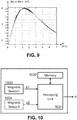
- the magnetic sensor device 130 may comprise a plurality of magnetic sensors (e.g. at least four Horizontal Hall elements, or at least two Vertical Hall elements) for measuring at least two magnetic field components (for example two in-plane magnetic field components Bx, By).
- This magnetic sensor device 130 may be configured for determining an absolute angular position ⁇ of the rotary button 120 based on said at least two measured field components.
- This embodiment offers the advantage that the angular position can be determine more accurately, over a larger range (e.g. 360°), and that it is more robust to ageing or demagnetisation of the magnet.
- buttons having an axially magnetized magnet with a cross section other than square or rectangular or circular can also be used.
- Suitable sensor devices are for example described in WO2014029885A1 , which document is incorporated herein in its entirety, especially the sections describing sensor arrangements for measuring the magnetic field at several locations and in particular directions, and the sections with formulas for calculating the angular position of a multipole magnet, more specifically for a quadrupole.
- suitable sensor devices typically comprise a plurality of sensor elements which are spaced apart, and which are oriented in predefined directions. The angular position can be calculated for example using on a arctan function of a ratio of difference signals. It is pointed out however, that the present invention is not limited only to the sensor devices described in WO2014029885A1 , and other suitable sensor devices may also be used.
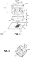
- the multipole magnet 1722 is a four-pole magnet, also known as quadrupole, but the invention also works for magnets having more than four poles, for example having six or eight poles.
Claims (15)
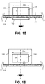
- Drehknopfsystem (100) zur Verwendung in einem Haushaltsgerät, umfassend:- eine ferromagnetische Platte (110);- einen Drehknopf (120), der abnehmbar in einem vordefinierten ersten Abstand (dm) von der ferromagnetischen Platte (110) auf einer ersten Seite der Platte montiert werden kann und um eine virtuelle Drehachse (105), die im Wesentlichen senkrecht zur Platte ist, drehbar ist und einen Permanentmagneten (122) umfasst, der in einer Richtung (X, Y), die im Wesentlichen senkrecht zur Drehachse (105) ist, magnetisiert ist;- eine Magnetsensorvorrichtung (130), die in einem vordefinierten zweiten Abstand (ds) von der ferromagnetischen Platte (110) auf einer zweiten Seite der Platte gegenüber der ersten Seite montiert ist;- und wobei die Magnetsensorvorrichtung (130) mindestens einen Magnetsensor zum Messen mindestens einer Magnetfeldkomponente (By) umfasst und zum Bestimmen einer Winkelposition (a) des Drehknopfes (120) auf der Grundlage der mindestens einen Magnetfeldkomponente (By) ausgelegt ist, und/oder
wobei die Magnetsensorvorrichtung (130) mindestens zwei Magnetsensoren umfasst und zum Bestimmen mindestens eines Magnetfeldgradienten (dBx/dx) und zum Bestimmen einer Winkelposition (a) des Drehknopfes (120) auf der Grundlage des mindestens einen Magnetfeldgradienten ausgelegt ist. - Drehknopfsystem (100) nach Anspruch 1, wobei die Magnetsensorvorrichtung mindestens zwei Magnetsensoren (HH1-HH4; VH1, VH2) zum Messen von mindestens zwei Magnetfeldkomponenten (Bx, By) in unterschiedlichen Richtungen (X, Y) umfasst und zum Bestimmen einer Winkelposition (a) des Drehknopfes (120) auf der Grundlage der mindestens zwei Magnetfeldkomponenten (Bx, By) ausgelegt ist.
- Drehknopfsystem (100) nach Anspruch 1 oder 2,
wobei die Magnetsensorvorrichtung (130) mindestens vier Magnetsensoren zum Messen von mindestens vier Magnetfeldkomponenten umfasst und zum Bestimmen von mindestens zwei Magnetfeldgradienten (dBx/dx, dBy/dy) in unterschiedlichen Richtungen (X, Y) und zum Bestimmen einer Winkelposition (a) des Drehknopfes (120) auf der Grundlage der mindestens zwei Magnetfeldgradienten ausgelegt ist. - Drehknopfsystem (100) nach einem der vorhergehenden Ansprüche, wobei die ferromagnetische Platte (110) eine Rundscheibenform aufweist.
- Drehknopfsystem (100) nach einem der vorhergehenden Ansprüche, wobei die ferromagnetische Platte (110) eine rechteckige Form aufweist.
- Drehknopfsystem (100) nach einem der vorhergehenden Ansprüche, wobei die ferromagnetische Platte eine Dicke (Tp) im Bereich von 0,3 bis 1,0 mm aufweist.
- Drehknopfsystem (100) nach einem der vorhergehenden Ansprüche,
wobei die Magnetsensorvorrichtung (130) im Wesentlichen auf der Drehachse (105) angeordnet ist. - Drehknopfsystem (100) nach einem der vorhergehenden Ansprüche,
wobei der Magnetsensorvorrichtung (130) eine Vielzahl von Magnetsensoren (HH1-HH4; VH1, VH2) aufweist, die zum Messen von mindestens zwei in der Ebene liegenden Magnetfeldkomponenten (Bx, By) in verschiedenen Richtungen (X, Y) und zum Bestimmen der Winkelposition (a) auf der Grundlage der in der Ebene liegenden Magnetfeldkomponenten (Bx, By) ausgelegt sind. - Drehknopfsystem (100) nach einem der vorhergehenden Ansprüche,
wobei die Magnetsensorvorrichtung (130) mindestens ein erstes vertikales Hall-Element (VH1) mit einer ersten Achse maximaler Empfindlichkeit in einer ersten Richtung (X) und ein zweites vertikales Hall-Element (VH2) mit einer zweiten Achse maximaler Empfindlichkeit parallel in einer zweiten Richtung (Y) umfasst, wobei die erste und die zweite Richtung im Wesentlichen parallel zur ferromagnetischen Platte (110) sind. - Drehknopfsystem (100) nach einem der vorhergehenden Ansprüche,
wobei die Magnetsensorvorrichtung (130) mindestens vier horizontale Hall-Elemente (HH1-HH4) und mindestens einen integrierten Magnetkonzentrator (510) umfasst. - Drehknopfsystem (100) nach einem der vorhergehenden Ansprüche,
wobei der Permanentmagnet (122; 1222; 1322; 1422) einer der folgenden Magnete ist:- ein diametral magnetisierter Rundscheibenmagnet (122), der im Wesentlichen koaxial zur Drehachse (105) angeordnet ist;- ein diametral magnetisierter Ringmagnet (1322), der im Wesentlichen koaxial zur Drehachse (1305) angeordnet ist;- ein axial magnetisierter Magnet (1422), der derart angeordnet ist, dass die axiale Richtung des Magneten im Wesentlichen senkrecht zur Rotationsachse (1405) ist;- ein mehrpoliger Rundscheibenmagnet (1722) oder ein mehrpoliger Ringmagnet, der in einer Ebene magnetisiert ist, die im Wesentlichen senkrecht zur Drehachse (105) ist. - Drehknopfsystem (100) nach einem der vorhergehenden Ansprüche,
wobei der Magnet (122) ein diametral magnetisierter Rundscheibenmagnet mit einem Durchmesser (Dm) im Bereich von 4 bis 14 mm ist;
oder wobei der Magnet (122) ein mehrpoliger Ringmagnet oder ein mehrpoliger Rundscheibenmagnet (1722) mit einem Durchmesser (Dm) im Bereich von 4 bis 14 mm ist;
oder wobei der Magnet (122) ein axial magnetisierter Magnet mit einer axialen Länge (Lm) im Bereich von 4 bis 14 mm ist. - Drehknopfsystem (100) nach einem der vorhergehenden Ansprüche, wobei der zweite Abstand (ds) zwischen der Magnetsensorvorrichtung (130) und der ferromagnetischen Platte (110) ein Wert im Bereich von 0,5 bis 6,5 mm ist.
- Drehknopfsystem (100) nach einem der vorhergehenden Ansprüche,
wobei der Magnet (122) ein diametral magnetisierter Rundscheibenmagnet mit einem Durchmesser (Dm) im Bereich von 4 bis 14 mm ist oder ein axial magnetisierter Magnet mit einer axialen Länge (Lm) im Bereich von 4 bis 14 mm ist;
und wobei der erste Abstand (dm) zwischen der ferromagnetischen Platte (110) und dem Magneten (122) ein Wert im Bereich von 0,5 bis 1,5 mm ist;
und wobei die ferromagnetische Platte (110) eine Dicke (Tp) im Bereich von 0,3 bis 1,0 mm aufweist;
und wobei der zweite Abstand (ds) zwischen der ferromagnetischen Platte (110) und der Magnetsensorvorrichtung (130) ein Wert im Bereich von 1,0 bis 4,5 mm ist. - Drehknopfsystem (100) nach einem der vorhergehenden Ansprüche,- wobei die Magnetsensorvorrichtung (130) mindestens einen Magnetsensor zum Messen der mindestens einen Magnetfeldkomponente umfasst und ferner dafür ausgelegt ist, eine Anwesenheit des Knopfes im vordefinierten Abstand von der ferromagnetischen Platte durch Vergleichen einer Größe der mindestens einen Magnetfeldkomponente mit einem vordefinierten Schwellenwert zu bestimmen;
oder wobei die Magnetsensorvorrichtung (130) mindestens zwei Magnetsensoren umfasst und ferner dafür ausgelegt ist, eine Anwesenheit des Knopfes im vordefinierten Abstand von der ferromagnetischen Platte durch Prüfen, ob mindestens eine der von diesen Sensoren bereitgestellten Magnetfeldkomponenten größer als ein vordefinierter Schwellenwert ist, zu bestimmen;
oder wobei die Magnetsensorvorrichtung (130) mindestens zwei in Quadratur angeordnete Magnetsensoren umfasst und ferner dafür ausgelegt ist, eine Anwesenheit des Knopfes im vordefinierten Abstand von der ferromagnetischen Platte durch Vergleichen einer Summe von Quadraten der von diesen Sensoren bereitgestellten Magnetfeldkomponenten mit einem vordefinierten Schwellenwert zu bestimmen.
Priority Applications (3)
| Application Number | Priority Date | Filing Date | Title |
|---|---|---|---|
| EP19154032.7A EP3686560B1 (de) | 2019-01-28 | 2019-01-28 | Magnetisches drehknopf-system |
| CN202010048008.0A CN111488030B (zh) | 2019-01-28 | 2020-01-16 | 磁性吸引旋转式按钮系统 |
| US16/745,972 US11257643B2 (en) | 2019-01-28 | 2020-01-17 | Magnetic attractive rotary button system |
Applications Claiming Priority (1)
| Application Number | Priority Date | Filing Date | Title |
|---|---|---|---|
| EP19154032.7A EP3686560B1 (de) | 2019-01-28 | 2019-01-28 | Magnetisches drehknopf-system |
Publications (2)
| Publication Number | Publication Date |
|---|---|
| EP3686560A1 EP3686560A1 (de) | 2020-07-29 |
| EP3686560B1 true EP3686560B1 (de) | 2021-07-14 |
Family
ID=65241189
Family Applications (1)
| Application Number | Title | Priority Date | Filing Date |
|---|---|---|---|
| EP19154032.7A Active EP3686560B1 (de) | 2019-01-28 | 2019-01-28 | Magnetisches drehknopf-system |
Country Status (3)
| Country | Link |
|---|---|
| US (1) | US11257643B2 (de) |
| EP (1) | EP3686560B1 (de) |
| CN (1) | CN111488030B (de) |
Families Citing this family (3)
| Publication number | Priority date | Publication date | Assignee | Title |
|---|---|---|---|---|
| GB2540599B (en) * | 2015-07-22 | 2021-04-14 | Cmr Surgical Ltd | Rotary encoder. |
| EP3875915B1 (de) * | 2020-03-06 | 2023-07-19 | Melexis Technologies SA | Vorrichtung, system und verfahren zur bestimmung einer position eines magneten |
| EP4105768B1 (de) * | 2021-06-18 | 2024-03-06 | Melexis Technologies SA | Vorrichtung und verfahren zur bestimmung der orientierung eines magneten und joystick |
Family Cites Families (17)
| Publication number | Priority date | Publication date | Assignee | Title |
|---|---|---|---|---|
| JPH09508214A (ja) | 1994-11-22 | 1997-08-19 | ローベルト ボツシユ ゲゼルシヤフト ミツト ベシユレンクテル ハフツング | 回転可能部材の無接触形回転角検出装置 |
| US6556005B1 (en) * | 2000-01-27 | 2003-04-29 | Goodrich Avionics Systems, Inc. | Magnetic encoder apparatus capable of resolving axial and rotational displacements |
| EP1610095B1 (de) * | 2004-06-21 | 2016-08-10 | Baumer Electric AG | Drehgeber zur Bestimmung des absoluten Drehwinkels einer Welle |
| US8901921B2 (en) * | 2009-11-25 | 2014-12-02 | Infineon Technologies Ag | Angle measurement system for determining an angular position of a rotating shaft |
| GB2505226A (en) | 2012-08-23 | 2014-02-26 | Melexis Technologies Nv | Arrangement, method and sensor for measuring an absolute angular position using a multi-pole magnet |
| CN103591969B (zh) * | 2012-08-28 | 2016-01-20 | 王嘉 | 具有内置磁铁盘的防水编码装置 |
| DE102013219018A1 (de) * | 2012-12-20 | 2014-06-26 | Continental Teves Ag & Co. Ohg | Winkelsensors |
| US9671214B2 (en) * | 2013-07-17 | 2017-06-06 | Infineon Technologies Ag | Discrete magnetic angle sensor device, a magnetic angle sensor arrangement, a method for generating an angle signal and a method for providing a sensor signal |
| US10024690B2 (en) * | 2015-04-14 | 2018-07-17 | Texas Instruments Incorporated | Incremental rotary encoder using hall effect sensors and magnetic detents |
| CN204731676U (zh) * | 2015-07-13 | 2015-10-28 | 浙江绍兴苏泊尔生活电器有限公司 | 调节旋钮及电器产品 |
| CN105281732B (zh) | 2015-10-19 | 2018-04-17 | 宁波方太厨具有限公司 | 一种感应式开关旋钮及其编码方法 |
| US10269515B2 (en) * | 2016-09-08 | 2019-04-23 | Touchsensor Technologies, Llc | Magnetic encoder knob with fixed center |
| EP3321638B1 (de) | 2016-11-14 | 2019-03-06 | Melexis Technologies SA | Messung einer absoluten winkelposition |
| EP3367067B1 (de) * | 2017-02-28 | 2019-07-03 | Melexis Technologies SA | Positionssensor und positionserfassungsverfahren |
| EP3385678B1 (de) * | 2017-04-06 | 2021-07-28 | Melexis Technologies SA | Drehpositionssensor |
| US10903030B2 (en) * | 2017-04-27 | 2021-01-26 | Magswitch Technology Worldwide Pty Ltd. | Variable field magnetic couplers and methods for engaging a ferromagnetic workpiece |
| EP3415871A1 (de) * | 2017-06-12 | 2018-12-19 | Fraba B.V. | Sensoranordnung zur erfassung von magnetfeldlinien eines magnetfeldes, bzw. erfassungsanordnung, bzw. drehwinkelmesssystem |
-
2019
- 2019-01-28 EP EP19154032.7A patent/EP3686560B1/de active Active
-
2020
- 2020-01-16 CN CN202010048008.0A patent/CN111488030B/zh active Active
- 2020-01-17 US US16/745,972 patent/US11257643B2/en active Active
Also Published As
| Publication number | Publication date |
|---|---|
| CN111488030A (zh) | 2020-08-04 |
| US11257643B2 (en) | 2022-02-22 |
| CN111488030B (zh) | 2022-08-02 |
| US20200243285A1 (en) | 2020-07-30 |
| EP3686560A1 (de) | 2020-07-29 |
Similar Documents
| Publication | Publication Date | Title |
|---|---|---|
| US11257643B2 (en) | Magnetic attractive rotary button system | |
| US20210364325A1 (en) | Magnetic angular position sensor | |
| EP3184954B1 (de) | Magnetoresistiver winkelsensor | |
| CN104655004B (zh) | 同轴磁场角度传感器、系统和方法 | |
| CN108489379B (zh) | 具有扰动场抑制的角度传感器 | |
| CN104583727B (zh) | 用于使用多极磁体来测量绝对角位置的布置、方法和传感器 | |
| EP2952857B1 (de) | Absoluter, magnetischer, rotierender codierer | |
| CN105371874B (zh) | 真实-相位二维磁场传感器 | |
| US10732009B2 (en) | Angle sensing in an off-axis configuration | |
| CN103814508B (zh) | 包括致动器以及结合于致动器的磁轭内的传感器的紧凑型定位组件 | |
| EP2988279A1 (de) | Magnetkopf zur erkennung eines magnetfeldes auf der oberfläche eines magnetischen musters auf der basis von magnetoresistiver technologie | |
| CN103529267A (zh) | 用于测量电流的电流变换器 | |
| US9268001B2 (en) | Differential perpendicular on-axis angle sensor | |
| US20160161574A1 (en) | Soft switching of magnetization in a magnetoresistive sensor | |
| Chiang et al. | Tri-axis magnetometer with in-plane giant magnetoresistance sensors for compass application | |
| US20150160307A1 (en) | Orthogonal fluxgate sensor | |
| CN102478405A (zh) | 磁式位置检测装置 | |
| US9697940B2 (en) | Apparatus and methods for generating a uniform magnetic field | |
| WO2013063773A1 (en) | Devices and methods for sensing current | |
| CN111426264B (zh) | 使用同质测试模式的传感器对准 | |
| KR20230101134A (ko) | 스핀 궤도 결합 토크를 이용한 자기 센서 및 그것을 이용한 센싱 방법 | |
| US6538432B1 (en) | Hysteresis loop tracer with symmetric balance coil | |
| JP2008014954A (ja) | 磁気センサ | |
| JP2006145323A (ja) | 回転角度検出装置 | |
| CN117178193A (zh) | 磁传感器和磁检测系统 |
Legal Events
| Date | Code | Title | Description |
|---|---|---|---|
| PUAI | Public reference made under article 153(3) epc to a published international application that has entered the european phase |
Free format text: ORIGINAL CODE: 0009012 |
|
| STAA | Information on the status of an ep patent application or granted ep patent |
Free format text: STATUS: THE APPLICATION HAS BEEN PUBLISHED |
|
| AK | Designated contracting states |
Kind code of ref document: A1 Designated state(s): AL AT BE BG CH CY CZ DE DK EE ES FI FR GB GR HR HU IE IS IT LI LT LU LV MC MK MT NL NO PL PT RO RS SE SI SK SM TR |
|
| AX | Request for extension of the european patent |
Extension state: BA ME |
|
| STAA | Information on the status of an ep patent application or granted ep patent |
Free format text: STATUS: REQUEST FOR EXAMINATION WAS MADE |
|
| 17P | Request for examination filed |
Effective date: 20210120 |
|
| RBV | Designated contracting states (corrected) |
Designated state(s): AL AT BE BG CH CY CZ DE DK EE ES FI FR GB GR HR HU IE IS IT LI LT LU LV MC MK MT NL NO PL PT RO RS SE SI SK SM TR |
|
| GRAP | Despatch of communication of intention to grant a patent |
Free format text: ORIGINAL CODE: EPIDOSNIGR1 |
|
| STAA | Information on the status of an ep patent application or granted ep patent |
Free format text: STATUS: GRANT OF PATENT IS INTENDED |
|
| INTG | Intention to grant announced |
Effective date: 20210226 |
|
| RIN1 | Information on inventor provided before grant (corrected) |
Inventor name: WANG, HAO |
|
| GRAS | Grant fee paid |
Free format text: ORIGINAL CODE: EPIDOSNIGR3 |
|
| GRAJ | Information related to disapproval of communication of intention to grant by the applicant or resumption of examination proceedings by the epo deleted |
Free format text: ORIGINAL CODE: EPIDOSDIGR1 |
|
| GRAL | Information related to payment of fee for publishing/printing deleted |
Free format text: ORIGINAL CODE: EPIDOSDIGR3 |
|
| STAA | Information on the status of an ep patent application or granted ep patent |
Free format text: STATUS: REQUEST FOR EXAMINATION WAS MADE |
|
| GRAP | Despatch of communication of intention to grant a patent |
Free format text: ORIGINAL CODE: EPIDOSNIGR1 |
|
| STAA | Information on the status of an ep patent application or granted ep patent |
Free format text: STATUS: GRANT OF PATENT IS INTENDED |
|
| INTC | Intention to grant announced (deleted) | ||
| GRAA | (expected) grant |
Free format text: ORIGINAL CODE: 0009210 |
|
| STAA | Information on the status of an ep patent application or granted ep patent |
Free format text: STATUS: THE PATENT HAS BEEN GRANTED |
|
| INTG | Intention to grant announced |
Effective date: 20210526 |
|
| AK | Designated contracting states |
Kind code of ref document: B1 Designated state(s): AL AT BE BG CH CY CZ DE DK EE ES FI FR GB GR HR HU IE IS IT LI LT LU LV MC MK MT NL NO PL PT RO RS SE SI SK SM TR |
|
| REG | Reference to a national code |
Ref country code: GB Ref legal event code: FG4D |
|
| REG | Reference to a national code |
Ref country code: DE Ref legal event code: R096 Ref document number: 602019006000 Country of ref document: DE |
|
| REG | Reference to a national code |
Ref country code: IE Ref legal event code: FG4D |
|
| REG | Reference to a national code |
Ref country code: AT Ref legal event code: REF Ref document number: 1411004 Country of ref document: AT Kind code of ref document: T Effective date: 20210815 |
|
| REG | Reference to a national code |
Ref country code: LT Ref legal event code: MG9D |
|
| REG | Reference to a national code |
Ref country code: NL Ref legal event code: MP Effective date: 20210714 |
|
| REG | Reference to a national code |
Ref country code: AT Ref legal event code: MK05 Ref document number: 1411004 Country of ref document: AT Kind code of ref document: T Effective date: 20210714 |
|
| PG25 | Lapsed in a contracting state [announced via postgrant information from national office to epo] |
Ref country code: ES Free format text: LAPSE BECAUSE OF FAILURE TO SUBMIT A TRANSLATION OF THE DESCRIPTION OR TO PAY THE FEE WITHIN THE PRESCRIBED TIME-LIMIT Effective date: 20210714 Ref country code: FI Free format text: LAPSE BECAUSE OF FAILURE TO SUBMIT A TRANSLATION OF THE DESCRIPTION OR TO PAY THE FEE WITHIN THE PRESCRIBED TIME-LIMIT Effective date: 20210714 Ref country code: RS Free format text: LAPSE BECAUSE OF FAILURE TO SUBMIT A TRANSLATION OF THE DESCRIPTION OR TO PAY THE FEE WITHIN THE PRESCRIBED TIME-LIMIT Effective date: 20210714 Ref country code: SE Free format text: LAPSE BECAUSE OF FAILURE TO SUBMIT A TRANSLATION OF THE DESCRIPTION OR TO PAY THE FEE WITHIN THE PRESCRIBED TIME-LIMIT Effective date: 20210714 Ref country code: NO Free format text: LAPSE BECAUSE OF FAILURE TO SUBMIT A TRANSLATION OF THE DESCRIPTION OR TO PAY THE FEE WITHIN THE PRESCRIBED TIME-LIMIT Effective date: 20211014 Ref country code: PT Free format text: LAPSE BECAUSE OF FAILURE TO SUBMIT A TRANSLATION OF THE DESCRIPTION OR TO PAY THE FEE WITHIN THE PRESCRIBED TIME-LIMIT Effective date: 20211115 Ref country code: NL Free format text: LAPSE BECAUSE OF FAILURE TO SUBMIT A TRANSLATION OF THE DESCRIPTION OR TO PAY THE FEE WITHIN THE PRESCRIBED TIME-LIMIT Effective date: 20210714 Ref country code: HR Free format text: LAPSE BECAUSE OF FAILURE TO SUBMIT A TRANSLATION OF THE DESCRIPTION OR TO PAY THE FEE WITHIN THE PRESCRIBED TIME-LIMIT Effective date: 20210714 Ref country code: BG Free format text: LAPSE BECAUSE OF FAILURE TO SUBMIT A TRANSLATION OF THE DESCRIPTION OR TO PAY THE FEE WITHIN THE PRESCRIBED TIME-LIMIT Effective date: 20211014 Ref country code: AT Free format text: LAPSE BECAUSE OF FAILURE TO SUBMIT A TRANSLATION OF THE DESCRIPTION OR TO PAY THE FEE WITHIN THE PRESCRIBED TIME-LIMIT Effective date: 20210714 Ref country code: LT Free format text: LAPSE BECAUSE OF FAILURE TO SUBMIT A TRANSLATION OF THE DESCRIPTION OR TO PAY THE FEE WITHIN THE PRESCRIBED TIME-LIMIT Effective date: 20210714 |
|
| PG25 | Lapsed in a contracting state [announced via postgrant information from national office to epo] |
Ref country code: PL Free format text: LAPSE BECAUSE OF FAILURE TO SUBMIT A TRANSLATION OF THE DESCRIPTION OR TO PAY THE FEE WITHIN THE PRESCRIBED TIME-LIMIT Effective date: 20210714 Ref country code: LV Free format text: LAPSE BECAUSE OF FAILURE TO SUBMIT A TRANSLATION OF THE DESCRIPTION OR TO PAY THE FEE WITHIN THE PRESCRIBED TIME-LIMIT Effective date: 20210714 Ref country code: GR Free format text: LAPSE BECAUSE OF FAILURE TO SUBMIT A TRANSLATION OF THE DESCRIPTION OR TO PAY THE FEE WITHIN THE PRESCRIBED TIME-LIMIT Effective date: 20211015 |
|
| REG | Reference to a national code |
Ref country code: DE Ref legal event code: R097 Ref document number: 602019006000 Country of ref document: DE |
|
| PG25 | Lapsed in a contracting state [announced via postgrant information from national office to epo] |
Ref country code: DK Free format text: LAPSE BECAUSE OF FAILURE TO SUBMIT A TRANSLATION OF THE DESCRIPTION OR TO PAY THE FEE WITHIN THE PRESCRIBED TIME-LIMIT Effective date: 20210714 |
|
| PLBE | No opposition filed within time limit |
Free format text: ORIGINAL CODE: 0009261 |
|
| STAA | Information on the status of an ep patent application or granted ep patent |
Free format text: STATUS: NO OPPOSITION FILED WITHIN TIME LIMIT |
|
| PG25 | Lapsed in a contracting state [announced via postgrant information from national office to epo] |
Ref country code: SM Free format text: LAPSE BECAUSE OF FAILURE TO SUBMIT A TRANSLATION OF THE DESCRIPTION OR TO PAY THE FEE WITHIN THE PRESCRIBED TIME-LIMIT Effective date: 20210714 Ref country code: SK Free format text: LAPSE BECAUSE OF FAILURE TO SUBMIT A TRANSLATION OF THE DESCRIPTION OR TO PAY THE FEE WITHIN THE PRESCRIBED TIME-LIMIT Effective date: 20210714 Ref country code: RO Free format text: LAPSE BECAUSE OF FAILURE TO SUBMIT A TRANSLATION OF THE DESCRIPTION OR TO PAY THE FEE WITHIN THE PRESCRIBED TIME-LIMIT Effective date: 20210714 Ref country code: EE Free format text: LAPSE BECAUSE OF FAILURE TO SUBMIT A TRANSLATION OF THE DESCRIPTION OR TO PAY THE FEE WITHIN THE PRESCRIBED TIME-LIMIT Effective date: 20210714 Ref country code: CZ Free format text: LAPSE BECAUSE OF FAILURE TO SUBMIT A TRANSLATION OF THE DESCRIPTION OR TO PAY THE FEE WITHIN THE PRESCRIBED TIME-LIMIT Effective date: 20210714 Ref country code: AL Free format text: LAPSE BECAUSE OF FAILURE TO SUBMIT A TRANSLATION OF THE DESCRIPTION OR TO PAY THE FEE WITHIN THE PRESCRIBED TIME-LIMIT Effective date: 20210714 |
|
| 26N | No opposition filed |
Effective date: 20220419 |
|
| PG25 | Lapsed in a contracting state [announced via postgrant information from national office to epo] |
Ref country code: IT Free format text: LAPSE BECAUSE OF FAILURE TO SUBMIT A TRANSLATION OF THE DESCRIPTION OR TO PAY THE FEE WITHIN THE PRESCRIBED TIME-LIMIT Effective date: 20210714 |
|
| PG25 | Lapsed in a contracting state [announced via postgrant information from national office to epo] |
Ref country code: MC Free format text: LAPSE BECAUSE OF FAILURE TO SUBMIT A TRANSLATION OF THE DESCRIPTION OR TO PAY THE FEE WITHIN THE PRESCRIBED TIME-LIMIT Effective date: 20210714 |
|
| REG | Reference to a national code |
Ref country code: CH Ref legal event code: PL |
|
| REG | Reference to a national code |
Ref country code: BE Ref legal event code: MM Effective date: 20220131 |
|
| PG25 | Lapsed in a contracting state [announced via postgrant information from national office to epo] |
Ref country code: LU Free format text: LAPSE BECAUSE OF NON-PAYMENT OF DUE FEES Effective date: 20220128 |
|
| PG25 | Lapsed in a contracting state [announced via postgrant information from national office to epo] |
Ref country code: BE Free format text: LAPSE BECAUSE OF NON-PAYMENT OF DUE FEES Effective date: 20220131 |
|
| PG25 | Lapsed in a contracting state [announced via postgrant information from national office to epo] |
Ref country code: LI Free format text: LAPSE BECAUSE OF NON-PAYMENT OF DUE FEES Effective date: 20220131 Ref country code: CH Free format text: LAPSE BECAUSE OF NON-PAYMENT OF DUE FEES Effective date: 20220131 |
|
| PG25 | Lapsed in a contracting state [announced via postgrant information from national office to epo] |
Ref country code: IE Free format text: LAPSE BECAUSE OF NON-PAYMENT OF DUE FEES Effective date: 20220128 |
|
| P01 | Opt-out of the competence of the unified patent court (upc) registered |
Effective date: 20230517 |
|
| GBPC | Gb: european patent ceased through non-payment of renewal fee |
Effective date: 20230128 |
|
| PG25 | Lapsed in a contracting state [announced via postgrant information from national office to epo] |
Ref country code: GB Free format text: LAPSE BECAUSE OF NON-PAYMENT OF DUE FEES Effective date: 20230128 |
|
| PGFP | Annual fee paid to national office [announced via postgrant information from national office to epo] |
Ref country code: FR Payment date: 20231219 Year of fee payment: 6 |
|
| PG25 | Lapsed in a contracting state [announced via postgrant information from national office to epo] |
Ref country code: MK Free format text: LAPSE BECAUSE OF FAILURE TO SUBMIT A TRANSLATION OF THE DESCRIPTION OR TO PAY THE FEE WITHIN THE PRESCRIBED TIME-LIMIT Effective date: 20210714 Ref country code: CY Free format text: LAPSE BECAUSE OF FAILURE TO SUBMIT A TRANSLATION OF THE DESCRIPTION OR TO PAY THE FEE WITHIN THE PRESCRIBED TIME-LIMIT Effective date: 20210714 |
|
| PGFP | Annual fee paid to national office [announced via postgrant information from national office to epo] |
Ref country code: DE Payment date: 20231219 Year of fee payment: 6 |