EP3686489B1 - Leuchte mit tragendem kühlblech - Google Patents
Leuchte mit tragendem kühlblech Download PDFInfo
- Publication number
- EP3686489B1 EP3686489B1 EP19216779.9A EP19216779A EP3686489B1 EP 3686489 B1 EP3686489 B1 EP 3686489B1 EP 19216779 A EP19216779 A EP 19216779A EP 3686489 B1 EP3686489 B1 EP 3686489B1
- Authority
- EP
- European Patent Office
- Prior art keywords
- housing
- heatsink
- web
- longitudinal axis
- led unit
- Prior art date
- Legal status (The legal status is an assumption and is not a legal conclusion. Google has not performed a legal analysis and makes no representation as to the accuracy of the status listed.)
- Active
Links
Images

Classifications
-
- F—MECHANICAL ENGINEERING; LIGHTING; HEATING; WEAPONS; BLASTING
- F21—LIGHTING
- F21V—FUNCTIONAL FEATURES OR DETAILS OF LIGHTING DEVICES OR SYSTEMS THEREOF; STRUCTURAL COMBINATIONS OF LIGHTING DEVICES WITH OTHER ARTICLES, NOT OTHERWISE PROVIDED FOR
- F21V29/00—Protecting lighting devices from thermal damage; Cooling or heating arrangements specially adapted for lighting devices or systems
- F21V29/50—Cooling arrangements
- F21V29/502—Cooling arrangements characterised by the adaptation for cooling of specific components
- F21V29/503—Cooling arrangements characterised by the adaptation for cooling of specific components of light sources
-
- F—MECHANICAL ENGINEERING; LIGHTING; HEATING; WEAPONS; BLASTING
- F21—LIGHTING
- F21S—NON-PORTABLE LIGHTING DEVICES; SYSTEMS THEREOF; VEHICLE LIGHTING DEVICES SPECIALLY ADAPTED FOR VEHICLE EXTERIORS
- F21S4/00—Lighting devices or systems using a string or strip of light sources
- F21S4/20—Lighting devices or systems using a string or strip of light sources with light sources held by or within elongate supports
- F21S4/28—Lighting devices or systems using a string or strip of light sources with light sources held by or within elongate supports rigid, e.g. LED bars
-
- F—MECHANICAL ENGINEERING; LIGHTING; HEATING; WEAPONS; BLASTING
- F21—LIGHTING
- F21V—FUNCTIONAL FEATURES OR DETAILS OF LIGHTING DEVICES OR SYSTEMS THEREOF; STRUCTURAL COMBINATIONS OF LIGHTING DEVICES WITH OTHER ARTICLES, NOT OTHERWISE PROVIDED FOR
- F21V15/00—Protecting lighting devices from damage
- F21V15/01—Housings, e.g. material or assembling of housing parts
- F21V15/013—Housings, e.g. material or assembling of housing parts the housing being an extrusion
-
- F—MECHANICAL ENGINEERING; LIGHTING; HEATING; WEAPONS; BLASTING
- F21—LIGHTING
- F21V—FUNCTIONAL FEATURES OR DETAILS OF LIGHTING DEVICES OR SYSTEMS THEREOF; STRUCTURAL COMBINATIONS OF LIGHTING DEVICES WITH OTHER ARTICLES, NOT OTHERWISE PROVIDED FOR
- F21V17/00—Fastening of component parts of lighting devices, e.g. shades, globes, refractors, reflectors, filters, screens, grids or protective cages
- F21V17/10—Fastening of component parts of lighting devices, e.g. shades, globes, refractors, reflectors, filters, screens, grids or protective cages characterised by specific fastening means or way of fastening
- F21V17/16—Fastening of component parts of lighting devices, e.g. shades, globes, refractors, reflectors, filters, screens, grids or protective cages characterised by specific fastening means or way of fastening by deformation of parts; Snap action mounting
- F21V17/164—Fastening of component parts of lighting devices, e.g. shades, globes, refractors, reflectors, filters, screens, grids or protective cages characterised by specific fastening means or way of fastening by deformation of parts; Snap action mounting the parts being subjected to bending, e.g. snap joints
-
- F—MECHANICAL ENGINEERING; LIGHTING; HEATING; WEAPONS; BLASTING
- F21—LIGHTING
- F21V—FUNCTIONAL FEATURES OR DETAILS OF LIGHTING DEVICES OR SYSTEMS THEREOF; STRUCTURAL COMBINATIONS OF LIGHTING DEVICES WITH OTHER ARTICLES, NOT OTHERWISE PROVIDED FOR
- F21V29/00—Protecting lighting devices from thermal damage; Cooling or heating arrangements specially adapted for lighting devices or systems
- F21V29/50—Cooling arrangements
- F21V29/70—Cooling arrangements characterised by passive heat-dissipating elements, e.g. heat-sinks
-
- F—MECHANICAL ENGINEERING; LIGHTING; HEATING; WEAPONS; BLASTING
- F21—LIGHTING
- F21Y—INDEXING SCHEME ASSOCIATED WITH SUBCLASSES F21K, F21L, F21S and F21V, RELATING TO THE FORM OR THE KIND OF THE LIGHT SOURCES OR OF THE COLOUR OF THE LIGHT EMITTED
- F21Y2115/00—Light-generating elements of semiconductor light sources
- F21Y2115/10—Light-emitting diodes [LED]
Definitions
- the invention relates to a lamp according to the preamble of claim 1.
- a lamp which uses LEDs (light emitting diodes) as light sources.
- LEDs light emitting diodes
- the entire housing is designed in the manner of a heat sink, with cooling fins.
- LED unit can be found in the data sheet, which was available on January 9, 2019 at the Internet address https://www.vossloh-schwabe.com/uploads/tx sbdownloader / LED-Line-SMD-Kit 3R-G DE.pdf known, each comprising a plurality of LEDs.
- the LED unit is assigned an optical unit which influences the light emitted by the LEDs.
- Tub lights for fluorescent tubes are also known, with reference to the example US 7 083 308 B2 is referred.
- the housing is designed like a trough, wherein it extends along a longitudinal axis, wherein it has a U-shaped cross-sectional shape with a base and two U-legs in a central region with respect to the longitudinal axis, the heat sink with a constant Cross-sectional shape extends along the longitudinal axis, wherein it has a central section which is arranged transversely to the longitudinal axis between two lateral sections, the central section forming a substantially flat contact surface facing away from the housing, the LED unit being fastened to the contact surface is, wherein the lateral sections each have at least one first web which is aligned essentially perpendicular to the contact surface, wherein it is formed in one piece with the central section, wherein the first webs each form a first free end of the heat sink which points towards the housing, the U-legs of the housing each having a second free end which points towards the heat sink, wherein it rests against an associated first free end, the LED
- a lamp which comprises an equipment carrier which is designed as a bent sheet metal part. On the side edges pointing transversely to the longitudinal direction, the device carrier has bends which serve for stiffening.
- the lamp according to the invention can be used as a replacement for the known tub lights, which have essentially the same structural dimensions as a known tub light.
- the lamp according to the invention is extremely simple. In addition to the electronic and lighting components available on the market, it only includes two other components, namely the housing and the heat sink. These two parts are designed to be particularly material-saving and thus inexpensive.
- the heat sink can be attached to the housing in a particularly simple manner, preferably solely by means of two screws. Nevertheless, the entire luminaire is inherently stable. In particular, no deformation of the heat sink due to its own weight can be observed.
- the two lateral sections each comprise a second web which is oriented perpendicular to the contact surface, it being arranged between the associated first web and the contact surface, the second web directly adjoining the contact surface.
- the second web is preferably formed in one piece with the first web and the central section. It also serves to increase the bending stiffness of the heat sink.
- the second web also ensures that the lateral sections of the heat sink encompass the LED and the optics unit in a U-shape, with the first free ends of the first webs pointing towards the housing at the same time.
- the first and the associated second web are connected to one another in one piece via a connecting section, so that they together form a U-shape.
- the heat sink can be implemented as a bent sheet metal part in a cost-effective manner.
- the sheet metal is preferably bent along a line parallel to the longitudinal axis.
- the heat sink is preferably made of aluminum. It is preferably formed by several bends from a flat plate of constant thickness. It is also conceivable to manufacture the heat sink using an extrusion process.
- the connecting section is preferably arranged approximately in one plane with a light-emitting surface of the optics unit, and it is most preferably set back somewhat.
- the U-shaped cross-sectional shape of the housing is covered with an end plate at both ends of the housing pointing away from one another in the direction of the longitudinal axis, the heat sink being attached exclusively to the two end plates.
- the end plates are preferably formed integrally with the remainder of the housing.
- the housing can be made by bending deformation from a flat plate of constant thickness, it being provided with a bend on each of its two edges facing away from each other transversely to the longitudinal axis, which forms a first U-leg, with it being on both of its edges with respect to the longitudinal axis ends pointing away from one another are each provided with a bend which forms an end plate, the end plates adjoining both U-legs essentially without a gap.
- the end plates are preferably firmly connected to the U-legs by means of blind rivets.
- bent-over fastening tabs are provided in one piece on the end plates.
- the housing is preferably made of sheet metal. It exists preferably made of steel, which is most preferably painted.
- the housing can also be made of plastic by injection molding.
- the housing is therefore designed similar to the housing of a known tub light.
- the unit consisting of heat sink, LED unit and optics unit can be attached to the housing in a similar way to the cover of a known diffuser light. Because of the high rigidity of the structural unit mentioned, only very few fastening elements are required for this, preferably only two.
- the housing preferably has a constant cross-sectional shape in the central area.
- the first web serves primarily to increase the second-degree moment of area of the heat sink with respect to the longitudinal axis.
- the entire heat sink is preferably designed in one piece.
- the optics unit can be composed of several optics sub-units which are assigned to different sections of the LED unit. The parts of the optics unit are preferably attached to the LED unit and / or the heat sink.
- the LED unit can be composed of several assemblies, it preferably comprising a single assembly. The assemblies mentioned are preferably attached directly to the heat sink.
- the U-legs are preferably aligned perpendicular to the base.
- the lateral sections of the heat sink are preferably designed mirror-symmetrically to one another.
- the middle section of the heat sink is preferably designed in the form of a flat plate with a constant thickness.
- the heat sink is preferably made from sheet metal.
- the first and / or the second free end preferably run parallel to the longitudinal axis.
- the first free ends preferably lie laterally against the respectively assigned second free end.
- the first free ends of the heat sink and the second free ends of the first U-legs are preferably flat in the area of the abutment mentioned.
- the at least one optics unit is preferably detachably connected to the LED unit, the parts mentioned being most preferably screwed together with the heat sink.
- the cross-sectional shape of the cooling body has an essentially constant thickness everywhere.
- the second free ends of the U-legs are each provided with a bead, on which an associated first free end of the cooling body rests in such a way that the surfaces of the cooling body and the first U-leg facing the environment are in there an escape are arranged. This prevents dirt and / or moisture from collecting at the corresponding joint.
- the heat sink is attached to the housing exclusively at its two ends pointing away from one another with respect to the longitudinal axis.
- the heat sink is preferably screwed to the housing there.
- Fastening tabs which are bent over at right angles are preferably provided in one piece on the heat sink, which are directly adjacent to the central section.
- a separate contact washer is preferably arranged between the aforementioned fastening tabs and the housing, which securely establishes an electrically conductive contact between the housing and the heat sink.
- the contact disk is preferably penetrated by a screw bolt, which also penetrates the fastening tab.
- the housing together with the heat sink, encloses a substantially closed cavity, a power supply unit to which the LED unit is electrically connected being arranged in the cavity.
- the power supply unit is preferably attached to the first base of the housing.
- the power supply unit is preferably designed in the manner of a constant current driver.
- the LEDs which are preferably connected in series, are consequently all supplied with a fixed, predetermined current, the voltage at the individual LEDs being set accordingly.
- the heat sink is made of aluminum, the housing being made of steel or plastic.
- a heat sink made of aluminum dissipates the waste heat from the LEDs particularly well.
- the proposed materials for the housing are particularly inexpensive.
- the LED unit comprises a circuit board on which a plurality of separate LEDs are distributed, the circuit board being attached to the middle section of the heat sink, the optics unit each having a funnel-like reflector in the area of the LEDs which is covered by a transparent or translucent material.
- Said material is preferably a plastic, most preferably polymethyl methacrylate (PMMA; also called acrylic glass).
- PMMA polymethyl methacrylate
- the circuit board and / or the optics unit is preferably screwed to the heat sink.
- the LEDs are preferably arranged in a grid-like manner on the board.
- Fig. 1 shows an exploded view of a lamp 10 according to the invention.
- the lamp 10 is shown in a position in which the housing 40 is down. This position is advantageous during the assembly of the lamp 10.
- the housing 40 is typically arranged at the top, it being fastened, for example, to the basic structure of an assembly workstation in order to illuminate a work area.
- the housing 40 is designed in the form of a bent sheet metal part which is made from sheet steel. But it can also be injection molded from plastic. It is also conceivable that the housing has a base body made of an extruded aluminum profile, the end plates 45 being designed as separate parts which are firmly connected to the base body.
- the housing 40 is designed like a trough. In a central region it extends with a constant cross-sectional shape along a longitudinal axis 11. The central region takes up almost the entire length of the housing 40. At the two ends of the housing 40 pointing away from one another in the direction of the longitudinal axis, an end plate 45 is provided, which is oriented perpendicular to the longitudinal axis 11. Said cross-sectional shape of the housing 40 is U-shaped with a base (No. 41 in Fig. 2 ) and two U-legs (No. 42 in Fig. 2 ) educated.
- the housing 40 is preferably designed as a bent sheet metal part.
- the blank is accordingly a flat plate of constant thickness, the border of which is cut to size in a common manner, for example by means of punching or laser cutting.
- the U-legs and the end plate 45 are each formed by an associated 90 ° bend.
- the end plates 45 are preferably each firmly connected to the two U-legs by means of blind rivets 47.
- a bent fastening tab 46 is preferably provided in one piece on the end plate 45.
- a power supply unit 60 is fastened, in particular screwed, to the base of the U-shape.
- the power supply unit 60 can be connected to the 230V alternating current network via the connection cable 61 which is led to the outside. It is preferably designed as a constant current driver, which generates a direct current suitable for operating the LEDs 51 with a predetermined current strength from the alternating mains voltage.
- a heat sink 20 is also provided, which consists of aluminum, and is preferably designed as a bent sheet metal part.
- the heat sink 20 forms a flat contact surface 23 which extends parallel to the longitudinal axis 11.
- An LED unit 50 rests directly on the contact surface 23 facing away from the housing 40, so that the waste heat generated there in the LEDs 51 (light emmitting diodes) can be given off to the environment with a low thermal resistance.
- the LED unit 50 is covered by an optical unit 70.
- the optics unit 70 is preferably designed in such a way that the point-like light emitted by the LEDs 51 is uniformly distributed in the room without the users of the room being dazzled by the very bright LEDs 51 when they look directly at the luminaire 10.
- the optics unit 70 is fastened together with the LED unit 50 to the heat sink 20 by means of screw bolts 73.
- the optics unit 70 comprises two optics subunits 72 which are identical to one another. Depending on the length of the luminaire 10, a suitable number of optics subunits 72 is selected.
- the LED unit 50 comprises a single circuit board 52, which is provided with a multiplicity of LEDs 51 arranged in a grid-like manner. The LEDs are preferably connected in series, any mixed forms of series and parallel connection being conceivable.
- the board is provided with two connection sockets 54. One connection socket 54 is electrically connected to the power supply unit 60 via the first connecting cable 53.
- connection socket 54 is short-circuited with a second connection cable 55.
- LED units can be connected to one opposite Fig. 1 to realize longer luminaires.
- the optical units 70 are closed at the end with separate end plates 75.
- the heat sink 20 is fixedly connected to the housing 40 exclusively at its ends pointing away from one another in the direction of the longitudinal axis 11.
- a fastening tab 28 is provided there in one piece on the heat sink 20, by means of which it is screwed to an associated end plate 45 of the housing 40.
- a contact disk 29 is located between the fastening tab 28 and the end plate 45 arranged, via which a reliable electrical connection between housing 40 and heat sink 20 is established.
- the heat sink rests exclusively on the housing 40 in a frictionally engaged manner, it even being possible within the scope of the present invention to dispense with a locking engagement which is difficult to produce.
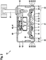
- Fig. 2 shows a cross section of the lamp 10 according to Fig. 1 .
- the heat sink 20 comprises a central section 21, which is arranged transversely to the longitudinal axis between two lateral sections 22.
- the middle section 21 is defined by the flat contact surface 23 to which the LED unit 50 and the optics unit 70 are attached.
- the contact surface 23 points away from the housing 40 so that the light from the LEDs 51 is emitted to the outside.
- the two lateral sections 22 serve to stiffen the heat sink 20 against bending deformation. They are therefore made significantly higher than the central section 21 perpendicular to the contact surface 23. As a result, the lateral sections 22 have a considerably higher second-degree moment of area than the central section 21.
- the two lateral sections 22 and the contact surface hold the LED -Unit 50 and the optics unit in a U-shape, so that overall a compact and rigid structural unit results, which can be attached to the housing 40 very easily and quickly. Despite the only two fastening points at the end, no noticeable bending deformation due to the weight of the assembly can be detected on this assembly.
- the lateral sections 22 each comprise a first and a second web 25; 26, which are aligned perpendicular to the contact surface 23.
- the two webs 25; 26 are integrally connected to one another via a connecting section 27, which is aligned essentially parallel to the contact surface 23, so that a U-shape results.
- the second web 26 is connected in one piece to the middle section 21, so that it is directly opposite the optics unit 70 laterally.
- the first web 25 has a first free end 24 which rests from the outside against a second free end 43 of an associated U-leg 42 of the base body 40.
- the second free end 43 is provided with a bead 44 or provided a recess, so that the outer surfaces of heat sink 20 and housing 40 are arranged in alignment in the area of mutual contact.
- the optics unit 70 comprises a funnel-like reflector 71 for each LED 51.
- a plate-like cover 76 made of transparent or translucent material is also provided.
Landscapes
- Engineering & Computer Science (AREA)
- General Engineering & Computer Science (AREA)
- Arrangement Of Elements, Cooling, Sealing, Or The Like Of Lighting Devices (AREA)
- Non-Portable Lighting Devices Or Systems Thereof (AREA)
Description
- Die Erfindung betrifft eine Leuchte gemäß dem Oberbegriff von Anspruch 1.
- Aus der
US 7 198 387 B1 ist eine Leuchte bekannt, welche LED's (light emitting diodes) als Leuchtmittel verwendet. Zwecks Abführung der in den LED's entstehenden Abwärme ist das gesamte Gehäuse in der Art eines Kühlkörpers ausgebildet, wobei es Kühlrippen aufweist. - Aus dem Datenblatt, welches am 09.01.2019 unter der Internetadresse https://www.vossloh-schwabe.com/uploads/tx sbdownloader/LED-Line-SMD-Kit 3R-G DE.pdf abrufbar war, ist eine LED-Einheit bekannt, welche jeweils eine Vielzahl von LED's umfasst. Der LED-Einheit ist eine Optik-Einheit zugeordnet, welche das von den LED's abgestrahlte Licht beeinflusst.
- Weiter sind Wannenleuchten für Leuchtstoffröhren bekannt, wobei beispielhaft auf die
US 7 083 308 B2 verwiesen wird. - Aus der
WO 2005/073629 A1 ist es bekannt, dass das Gehäuse wannenartig ausgebildet ist, wobei es sich entlang einer Längsachse erstreckt, wobei es in einem bezüglich der Längsachse mittleren Bereich eine U-förmige Querschnittsform mit einer Basis und zwei U-Schenkeln aufweist, wobei sich der Kühlkörper mit einer konstanten Querschnittsform entlang der Längsachse erstreckt, wobei er einen mittleren Abschnitt aufweist, welcher quer zur Längsachse zwischen zwei seitlichen Abschnitten angeordnet ist, wobei der mittlere Abschnitt eine im Wesentlichen ebene Anlagefläche bildet, welche vom Gehäuse weg weist, wobei die LED-Einheit an der Anlagefläche befestigt ist, wobei die seitlichen Abschnitte jeweils wenigstens einen ersten Steg aufweisen, welcher im Wesentlichen senkrecht zur Anlagefläche ausgerichtet ist, wobei er einstückig mit dem mittleren Abschnitt ausgebildet ist, wobei die ersten Stege jeweils ein erstes freies Ende des Kühlkörpers bilden, welches zum Gehäuse hin weist, wobei die U-Schenkel des Gehäuses jeweils ein zweites freies Ende aufweisen, welches zum Kühlkörper hin weist, wobei es an einem zugeordneten ersten freien Ende anliegt, wobei die LED-Einheit und/oder die wenigstens eine Optik-Einheit von den beiden seitlichen Abschnitten und dem mittleren Abschnitt U-förmig umfasst ist. Das Gehäuse und der Kühlkörper sind dabei als Strangpressprofile ausgeführt, welche nur in großen Stückzahlen wirtschaftlich herstellbar sind. - Aus der
DE 10 2017 203 203 A1 ist eine Leuchte bekannt, die einen Geräteträger umfasst, welcher als Blechbiegeteil ausgeführt ist. An den quer zur Längsrichtung weisenden Seitenrändern hat der Geräteträger Umbiegungen, welche der Versteifung dienen. - Ein Vorteil der vorliegenden Erfindung besteht darin, dass die erfindungsgemäße Leuchte als Ersatz für die bekannten Wannenleuchten verwendet werden kann, die im Wesentlichen die gleichen Baumaße aufweist wie eine bekannte Wannenleuchte. Die erfindungsgemäße Leuchte ist außerordentlich einfach ausgeführt. Neben den o.g. am Markt erhältlichen elektronischen bzw. leuchttechnischen Komponenten umfasst sie nur zwei weitere Bauteile, nämlich das Gehäuse und den Kühlkörper. Diese beiden Teile sind besonders materialsparend und damit kostengünstig gestaltet. Der Kühlkörper kann besonders einfach an dem Gehäuse befestigt werden, vorzugsweise allein mittels zweier Schrauben. Dennoch ist die gesamte Leuchte in sich stabil. Insbesondere eine Verformung des Kühlkörpers aufgrund seines Eigengewichts ist nicht zu beobachten.
- Erfindungsgemäß ist vorgesehen, dass die beiden seitlichen Abschnitte jeweils einen zweiten Steg umfassen, der senkrecht zur Anlagefläche ausgerichtet ist, wobei er zwischen dem zugeordneten ersten Steg und der Anlagefläche angeordnet ist, wobei der zweite Steg unmittelbar an die Anlagefläche angrenzt. Der zweite Steg ist vorzugsweise einstückig mit dem ersten Steg und dem mittleren Abschnitt ausgebildet. Er dient ebenfalls zur Erhöhung der Biegesteifigkeit des Kühlkörpers. Weiter wird mit dem zweiten Steg erreicht, dass die seitlichen Abschnitte des Kühlkörpers die LED- und die Optik-Einheit U-förmig umfassen, wobei gleichzeitig die ersten freien Enden der ersten Stege zum Gehäuse hin weisen.
- Erfindungsgemäß ist vorgesehen, dass der erste und der zugeordnete zweite Steg über einen Verbindungsabschnitt einstückig miteinander verbunden sind, so dass sie zusammen eine U-Form bilden. Auf diese Weise kann der Kühlkörper auf kostengünstige Weise als Blechbiegeteil realisiert werden. In den Ecken der genannten U-Form wird das Blech vorzugsweise entlang einer zur Längsachse parallelen Linie umgebogen. Der Kühlkörper besteht vorzugsweise aus Aluminium. Er ist vorzugsweise durch mehrere Umbiegungen aus einer ebenen Platte mit konstanter Dicke geformt. Es ist ebenfalls denkbar, den Kühlkörper im Strangpressverfahren herzustellen. Der Verbindungsabschnitt ist vorzugsweise in etwa in einer Ebene mit einer lichtabstrahlenden Oberfläche der Optik-Einheit angeordnet, wobei er höchst vorzugsweise etwas zurückgesetzt ist.
- Erfindungsgemäß ist vorgesehen, dass die U-förmige Querschnittsform des Gehäuses an beiden in Richtung der Längsachse voneinander weg weisenden Enden des Gehäuses mit einer Endplatte überdeckt ist, wobei der Kühlkörper ausschließlich an den beiden Endplatten befestigt ist. Die Endplatten sind vorzugsweise einstückig mit dem verbleibenden Gehäuse ausgebildet. Das Gehäuse kann durch Biegeverformung aus einer ebenen Platte mit konstanter Dicke hergestellt sein, wobei es an seinen beiden quer zur Längsachse voneinander weg weisenden Rändern jeweils mit einer Umbiegung versehen ist, welche einen ersten U-Schenkel bildet, wobei es an seinen beiden bezüglich der Längsachse voneinander weg weisenden Enden jeweils mit einer Umbiegung versehen ist, welche eine Endplatte bildet, wobei die Endplatten jeweils an beiden U-Schenkeln im Wesentlichen spaltfrei angrenzen. Die Endplatten sind vorzugsweise mittels Blindnieten mit den U-Schenkeln fest verbunden. An den Endplatten sind hierfür vorzugsweise umgebogene Befestigungslaschen einstückig vorgesehen. Das Gehäuse ist vorzugsweise aus Blech hergestellt. Es besteht vorzugsweise aus Stahl, welcher höchst vorzugsweise lackiert ist. Das Gehäuse kann auch aus Kunststoff im Spritzgussverfahren hergestellt sein.
- Das Gehäuse ist demnach ähnlich dem Gehäuse einer bekannten Wannenleuchte ausgeführt. Die Baueinheit aus Kühlkörper, LED-Einheit und Optik-Einheit kann ähnlich wie die Abdeckung einer bekannten Wannenleuchte am Gehäuse befestigt werden. Aufgrund der hohen Steifigkeit der genannten Baueinheit sind hierfür nur sehr wenige Befestigungselemente erforderlich, vorzugsweise nur zwei.
- Das Gehäuse hat im mittleren Bereich vorzugsweise eine konstante Querschnittsform. Der erste Steg dient in erster Linie der Erhöhung des Flächenmoments 2. Grades des Kühlkörpers bezüglich der Längsachse. Der gesamte Kühlkörper ist vorzugsweise einstückig ausgebildet. Die Optik-Einheit kann aus mehreren Optik-Untereinheiten zusammengesetzt sein, die unterschiedlichen Abschnitten der LED-Einheit zugeordnet sind. Die Teile der Optik-Einheit sind vorzugsweise an der LED-Einheit und/oder dem Kühlkörper befestigt. Die LED-Einheit kann aus mehreren Baugruppen zusammengesetzt sein, wobei sie vorzugsweise eine einzige Baugruppe umfasst. Die genannten Baugruppen sind vorzugsweise unmittelbar am Kühlkörper befestigt. Die U-Schenkel sind vorzugsweise senkrecht zur Basis ausgerichtet. Die seitlichen Abschnitte des Kühlkörpers sind vorzugsweise spiegelsymmetrisch zueinander ausgebildet. Der mittlere Abschnitt des Kühlkörpers ist vorzugsweise in Form einer ebenen Platte mit konstanter Dicke ausgebildet. Der Kühlkörper ist vorzugsweise aus Blech hergestellt. Das erste und/oder das zweite freie Ende verlaufen vorzugsweise parallel zu Längsachse. Die ersten freien Enden liegen vorzugsweise seitlich an dem jeweils zugeordneten zweiten freien Ende an. Die ersten freien Enden des Kühlkörpers und die zweiten freien Enden der ersten U-Schenkel sind im Bereich der genannten Anlage vorzugsweise eben ausgebildet. Die wenigstens eine Optik-Einheit ist vorzugsweise lösbar mit der LED-Einheit verbunden, wobei die genannten Teile höchst vorzugsweise gemeinsam mit dem Kühlkörper verschraubt sind.
- In den abhängigen Ansprüchen sind vorteilhafte Weiterbildungen und Verbesserungen der Erfindung angegeben.
- Es kann vorgesehen sein, dass die Querschnittsform des Kühlkörpers überall eine im Wesentlichen konstante Dicke aufweist.
- Es kann vorgesehen sein, dass die zweiten freien Enden der U-Schenkel jeweils mit einer Sicke versehen sind, an welche jeweils ein zugeordnetes erstes freies Ende des Kühlkörpers derart anliegt, dass dort die zur Umgebung hin weisenden Oberflächen vom Kühlkörper und erstem U-Schenkel in einer Flucht angeordnet sind. Hierdurch wird verhindert, dass sich an der entsprechenden Fügestelle Schmutz und/oder Feuchtigkeit ansammelt.
- Es kann vorgesehen sein, dass der Kühlkörper ausschließlich an seinen beiden bezüglich der Längsachse voneinander weg weisenden Enden am Gehäuse befestigt ist. Vorzugsweise ist der Kühlkörper dort mit dem Gehäuse verschraubt. Vorzugsweise sind dort senkrecht umgebogene Befestigungslaschen am Kühlkörper einstückig vorgesehen, die unmittelbar an den mittleren Abschnitt angrenzen. Zwischen den genannten Befestigungslaschen und dem Gehäuse ist vorzugsweise eine gesonderte Kontaktscheibe angeordnet, welche einen elektrisch leitenden Kontakt zwischen dem Gehäuse und dem Kühlkörper sicher herstellt. Die Kontaktscheibe ist vorzugsweise von einem Schraubbolzen durchsetzt, welcher außerdem die Befestigungslasche durchsetzt.
- Es kann vorgesehen sein, dass das Gehäuse zusammen mit dem Kühlkörper einen im Wesentlichen abgeschlossenen Hohlraum umschließt, wobei in dem Hohlraum eine Stromversorgungseinheit angeordnet ist, an welche die LED-Einheit elektrisch angeschlossen ist. Die Stromversorgungseinheit ist vorzugsweise an der ersten Basis des Gehäuses befestigt. Die Stromversorgungseinheit ist vorzugsweise in der Art eines Konstantstromtreibers ausgebildet. Die vorzugsweise in Reihe geschalteteten LED's werden folglich alle mit einem fest vorgegebenen Strom versorgt, wobei sich die Spannung an den einzelnen LED's entsprechend einstellt.
- Es kann vorgesehen sein, dass der Kühlkörper aus Aluminium besteht, wobei das Gehäuse aus Stahl oder aus Kunststoff besteht. Ein Kühlkörper aus Aluminium führt die Abwärme der LED's besonders gut ab. Die vorgeschlagenen Werkstoffe für das Gehäuse sind besonders kostengünstig.
- Es kann vorgesehen sein, dass die LED-Einheit eine Platine umfasst, auf der eine Vielzahl von gesonderten LED's verteilt angeordnet ist, wobei die Platine am mittleren Abschnitt des Kühlkörpers befestigt ist, wobei die Optik-Einheit im Bereich der LED's jeweils einen trichterartigen Reflektor aufweist, der von einem transparenten oder transluzenten Material überdeckt ist. Das genannte Material ist vorzugsweise ein Kunststoff, höchst vorzugsweise Polymethylmethacrylat (PMMA; auch Acrylglas genannt). Die Platine und/oder die Optik-Einheit ist vorzugsweise mit dem Kühlkörper verschraubt. Die LED's sind vorzugsweise rasterartig verteilt auf der Platine angeordnet.
- Es versteht sich, dass die vorstehend genannten und die nachfolgend noch zu erläuternden Merkmale nicht nur in der jeweils angegebenen Kombination, sondern auch in anderen Kombinationen oder in Alleinstellung verwendbar sind, ohne den Rahmen der vorliegenden Erfindung zu verlassen.
- Die Erfindung wird im Folgenden anhand der beigefügten Zeichnungen näher erläutert. Es zeigt:
- Fig. 1
- eine Explosionsansicht einer erfindungsgemäßen Leuchte; und
- Fig. 2
- einen Querschnitt der Leuchte nach
Fig. 1 . -
Fig. 1 zeigt eine Explosionsansicht einer erfindungsgemäßen Leuchte 10. Die Leuchte 10 ist in einer Stellung gezeigt, in welcher das Gehäuse 40 unten ist. Diese Stellung ist während der Montage der Leuchte 10 vorteilhaft. Im Betrieb ist das Gehäuse 40 typischerweise oben angeordnet, wobei es beispielsweise an dem Grundgerüst eines Montagearbeitsplatzes befestigt ist, um einen Arbeitsbereich auszuleuchten. - Das Gehäuse 40 ist vorliegend in Form eines Blechbiegeteils ausgeführt, welches aus Stahlblech hergestellt ist. Es kann aber auch aus Kunststoff spritzgegossen sein. Weiter ist es denkbar, dass das Gehäuse einen Grundkörper aus einem Aluminium-Strangpressprofil aufweist, wobei die Endplatten 45 als gesonderte Teile ausgebildet sind, welche mit dem Grundkörper fest verbunden sind.
- In all den genannten Fällen ist das Gehäuse 40 wannenartig ausgebildet. In einem mittleren Bereich erstreckt es sich mit einer konstanten Querschnittsform entlang einer Längsachse 11. Der mittlere Bereich nimmt dabei nahezu die gesamte Länge des Gehäuses 40 ein. An den beiden in Richtung der Längsachse voneinander weg weisenden Enden des Gehäuses 40 ist jeweils eine Endplatte 45 vorgesehen, welche senkrecht zur Längsachse 11 ausgerichtet ist. Die genannte Querschnittsform des Gehäuses 40 ist U-förmig mit einer Basis (Nr. 41 in
Fig. 2 ) und zwei U-Schenkeln (Nr. 42 inFig. 2 ) ausgebildet. Vorzugsweise ist das Gehäuse 40 als Blechbiegeteil ausgeführt. Das Rohteil ist dementsprechend eine ebene Platte mit konstanter Dicke, deren Umrandung in geeinter Weise zugeschnittenen ist, beispielsweise mittels Stanzen oder Laserstrahlschneiden. Die U-Schenkel und die Endplatte 45 werden jeweils durch eine zugeordnete 90°-Umbiegung gebildet. Die Endplatten 45 sind vorzugsweise jeweils mittels Blindnieten 47 fest mit den beiden U-Schenkeln verbunden. Hierfür ist vorzugsweise jeweils eine umgebogene Befestigungslasche 46 einstückig an der Endplatte 45 vorgesehen. - An der Basis der U-Form ist eine Stromversorgungseinheit 60 befestigt, insbesondere verschraubt. Die Stromversorgungseinheit 60 ist über das nach außen geführte Anschlusskabel 61 an das 230V-Wechselstromnetz anschließbar. Sie ist vorzugsweise als Konstantstromtreiber ausgeführt, welches aus der Netz-Wechselspannung einen zum Betrieb der LED's 51 geeigneten Gleichstrom mit vorgegebener Stromstärke erzeugt. Hinzuweisen ist auf die Schutzleiter 62, über die alle metallischen Teile der Leuchte 10, die von außen berührbar sind, mit dem Schutzleiter der Netzversorgung elektrisch verbunden sind.
- Weiter ist ein Kühlkörper 20 vorgesehen, welcher aus Aluminium besteht, wobei er vorzugsweise als Blechbiegeteil ausgebildet ist. Der Kühlkörper 20 bildet eine ebene Anlagefläche 23, welche sich parallel zur Längsachse 11 erstreckt. An der vom Gehäuse 40 abgewandten Anlagefläche 23 liegt eine LED-Einheit 50 unmittelbar an, so dass die dort in den LED's 51 (light emmitting diodes) entstehende Abwärme mit geringem Wärmeleitwiderstand an die Umgebung abgegeben werden kann. Die LED-Einheit 50 ist von einer Optik-Einheit 70 überdeckt. Die Optik-Einheit 70 ist vorzugsweise so gestaltet, dass das punktartig von den LED's 51 abgestrahlte Licht gleichförmig im Raum verteilt wird, ohne dass die Benutzer des Raumes von den sehr hellen LED's 51 geblendet werden, wenn sie direkt zur Leuchte 10 sehen.
- Die Optik-Einheit 70 ist zusammen mit der LED-Einheit 50 mittels Schraubbolzen 73 an dem Kühlkörper 20 befestigt. Vorliegend umfasst die Optik-Einheit 70 zwei untereinander identisch ausgeführte Optik-Untereinheiten 72. Je nach Länge der Leuchte 10 wird eine geeignete Anzahl an Optik-Untereinheiten 72 ausgewählt. Die LED-Einheit 50 umfasst vorliegend eine einzige Platine 52, welche mit einer Vielzahl von rasterartig verteilt angeordneten LED's 51 versehen ist. Die LED's sind vorzugsweise in Reihe geschaltet, wobei beliebige Mischformen von Reihen- und Parallelschaltung denkbar sind. Die Platine ist mit zwei Anschlussbuchsen 54 versehen. Die eine Anschlussbuchse 54 ist über das erste Verbindungskabel 53 elektrisch an die Stromversorgungseinheit 60 angeschlossen. Die andere Anschlussbuchse 54 ist vorliegend mit einem zweiten Verbindungskabel 55 kurzgeschlossen. Dort können weitere identisch ausgebildete LED-Einheiten angeschlossen werden, um eine gegenüber
Fig. 1 längere Leuchte zu realisieren. An den beiden in Richtung der Längsachse 11 voneinander weg weisenden Enden sind die Optik-Einheiten 70 mit gesonderten Endplatten 75 stirnseitig verschlossen. - Der Kühlkörper 20 ist ausschließlich an seinen in Richtung der Längsachse 11 voneinander weg weisenden Enden fest mit dem Gehäuse 40 verbunden. Dort ist jeweils eine Befestigungslasche 28 am Kühlkörper 20 einstückig vorgesehen, über welche er mit einer zugeordneten Endplatte 45 des Gehäuses 40 verschraubt ist. Zwischen der Befestigungslasche 28 und der Endplatte 45 ist eine Kontaktscheibe 29 angeordnet, über welche eine zuverlässige elektrische Verbindung zwischen Gehäuse 40 und Kühlkörper 20 hergestellt wird. Abseits dieser Verschraubung 30 liegt der Kühlkörper ausschließlich reibschlüssig am Gehäuse 40 an, wobei im Rahmen der vorliegenden Erfindung sogar auf einen schwer herzustellenden Rasteingriff verzichtet werden kann.
-
Fig. 2 zeigt einen Querschnitt der Leuchte 10 nachFig. 1 . Der Kühlkörper 20 umfasst einen mittleren Abschnitt 21, welcher quer zur Längsachse zwischen zwei seitlichen Abschnitten 22 angeordnet ist. Der mittlere Abschnitt 21 wird von der ebenen Anlagefläche 23 definiert, an welcher die LED-Einheit 50 und die Optik-Einheit 70 befestigt sind. Die Anlagefläche 23 weist vom Gehäuse 40 weg, damit das Licht der LED's 51 nach außen abgestrahlt wird. Die beiden seitlichen Abschnitte 22 dienen der Versteifung des Kühlkörpers 20 gegen Biegeverformung. Sie sind daher senkrecht zur Anlagefläche 23 deutlich höher ausgeführt als der mittlere Abschnitt 21. In der Folge haben die seitlichen Abschnitte 22 ein erheblich höheres Flächenmoment 2. Grades als der mittlere Abschnitt 21. Darüber hinaus fassen die beiden seitlichen Abschnitte 22 und die Anlagefläche die LED-Einheit 50 und die Optik-Einheit U-förmig ein, so dass sich insgesamt eine kompakte und steife Baueinheit ergibt, die sich sehr einfach und schnell am Gehäuse 40 befestigen lässt. Trotz der nur zwei endseitigen Befestigungspunkte ist an dieser Baugruppe keine merkliche Biegeverformung aufgrund des Eigengewichts der Baugruppe feststellbar. - Die seitlichen Abschnitte 22 umfassen jeweils einen ersten und einen zweiten Steg 25; 26, welche senkrecht zur Anlagefläche 23 ausgerichtet sind. Die beiden Stege 25; 26 sind über einen Verbindungsabschnitt 27, der im Wesentlichen parallel zur Anlagefläche 23 ausgerichtet ist, einstückig miteinander verbunden, so dass sich eine U-Form ergibt. An dem vom Verbindungsabschnitt 27 abgewandten Ende ist der zweite Steg 26 einstückig mit dem mittleren Abschnitt 21 verbunden, so dass er der Optik-Einheit 70 seitlich unmittelbar gegenübersteht. Der erste Steg 25 weist an dem vom Verbindungsabschnitt 27 abgewandten Ende ein erstes freies Ende 24 auf, welches von außen an einem zweiten freien Ende 43 eines zugeordneten U-Schenkels 42 des Grundkörpers 40 anliegt. Das zweite freie Ende 43 ist mit einer Sicke 44 bzw. einer Vertiefung versehen, so dass die Außenflächen von Kühlkörper 20 und Gehäuse 40 im Bereich des gegenseitigen Berührkontakts in einer Flucht angeordnet sind.
- Die Optik-Einheit 70 umfasst für jede LED 51 einen trichterartig ausgebildeten Reflektor 71. Weiter ist eine plattenartige Abdeckung 76 aus transparentem oder transluzentem Material vorgesehen.
-
- 10
- Leuchte
- 11
- Längsachse
- 12
- Hohlraum
- 20
- Kühlkörper
- 21
- mittlerer Abschnitt
- 22
- seitlicher Abschnitt
- 23
- Anlagefläche
- 24
- erstes freies Ende
- 25
- erster Steg
- 26
- zweiter Steg
- 27
- Verbindungsabschnitt
- 28
- Befestigungslasche
- 29
- Kontaktscheibe
- 30
- Schraubbolzen
- 40
- Gehäuse
- 41
- Basis
- 42
- U-Schenkel
- 43
- zweites freies Ende
- 44
- Sicke
- 45
- Endplatte
- 46
- Befestigungslasche
- 47
- Blindniet
- 50
- LED-Einheit
- 51
- LED
- 52
- Platine
- 53
- erstes Verbindungskabel
- 54
- Anschlussbuchse
- 55
- zweites Verbindungskabel
- 60
- Stromversorgungseinheit
- 61
- Anschlusskabel
- 62
- Schutzleiter
- 70
- Optik-Einheit
- 71
- Reflektor
- 72
- Optik-Untereinheit
- 73
- Schraubbolzen
- 75
- Endplatte
- 76
- Abdeckung
Claims (7)
- Leuchte (10) mit einer LED-Einheit (50), wenigstens einer Optik-Einheit (70), einem Kühlkörper (20) und einem Gehäuse (40), wobei die LED-Einheit (50) mehrere gesonderte LED's (51) umfasst, wobei sie derart an dem Kühlkörper (20) befestigt ist, dass Abwärme der LED's (51) über den Kühlkörper (20) zumindest mittelbar an die Umgebung abführbar ist, wobei die Optik-Einheit (70) derart mit der LED-Einheit (50) verbunden ist, dass sie das von den LED's (51) abstrahlbare Licht beeinflusst, wobei das Gehäuse (40) wannenartig ausgebildet ist, wobei es sich entlang einer Längsachse (11) erstreckt, wobei es in einem bezüglich der Längsachse (11) mittleren Bereich eine U-förmige Querschnittsform mit einer Basis (41) und zwei U-Schenkeln (42) aufweist, wobei sich der Kühlkörper (20) mit einer konstanten Querschnittsform entlang der Längsachse (11) erstreckt, wobei er einen mittleren Abschnitt (21) aufweist, welcher quer zur Längsachse zwischen zwei seitlichen Abschnitten (22) angeordnet ist, wobei der mittlere Abschnitt (21) eine im Wesentlichen ebene Anlagefläche (23) bildet, welche vom Gehäuse (40) weg weist, wobei die LED-Einheit (50) an der Anlagefläche (23) befestigt ist, wobei die seitlichen Abschnitte (22) jeweils wenigstens einen ersten Steg (25) aufweisen, welcher im Wesentlichen senkrecht zur Anlagefläche ausgerichtet ist, wobei er einstückig mit dem mittleren Abschnitt (21) ausgebildet ist, wobei die ersten Stege (25) jeweils ein erstes freies Ende (24) des Kühlkörpers (20) bilden, welches zum Gehäuse (40) hin weist, wobei die U-Schenkel (42) des Gehäuses jeweils ein zweites freies Ende (43) aufweisen, welches zum Kühlkörper (20) hin weist, wobei es an einem zugeordneten ersten freien Ende (24) anliegt, wobei die LED-Einheit (50) und/oder die wenigstens eine Optik-Einheit (70) von den beiden seitlichen Abschnitten (22) und dem mittleren Anschnitt (21) U-förmig umfasst ist,
dadurch gekennzeichnet, dass die beiden seitlichen Abschnitte (22) jeweils einen zweiten Steg (26) umfassen, der senkrecht zur Anlagefläche (23) ausgerichtet ist, wobei er zwischen dem zugeordneten ersten Steg (25) und der Anlagefläche (23) angeordnet ist, wobei der zweite Steg (26) unmittelbar an die Anlagefläche (23) angrenzt, der erste und der zugeordnete zweite Steg (25; 26) über einen Verbindungsabschnitt (27) einstückig miteinander verbunden sind, so dass sie zusammen eine U-Form bilden, wobei die U-förmige Querschnittsform des Gehäuses (40) an beiden in Richtung der Längsachse (11) voneinander weg weisenden Enden des Gehäuses (40) mit einer Endplatte (45) überdeckt ist, wobei der Kühlkörper (20) ausschließlich an den beiden Endplatten (45) befestigt ist. - Leuchte nach Anspruch 1,
wobei die Querschnittsform des Kühlkörpers (20) überall eine im Wesentlichen konstante Dicke aufweist. - Leuchte nach einem der vorstehenden Ansprüche,
wobei die zweiten freien Enden (43) der U-Schenkel (42) jeweils mit einer Sicke (44) versehen sind, an welche jeweils ein zugeordnetes erstes freies Ende (24) des Kühlkörpers (20) derart anliegt, dass dort die zur Umgebung hin weisenden Oberflächen von Kühlkörper (20) und erstem U-Schenkel (42) in einer Flucht angeordnet sind. - Leuchte nach einem der vorstehenden Ansprüche,
wobei der Kühlkörper (20) ausschließlich an seinen beiden bezüglich der Längsachse (11) voneinander weg weisenden Enden am Gehäuse (40) befestigt ist. - Leuchte nach einem der vorstehenden Ansprüche,
wobei das Gehäuse (40) zusammen mit dem Kühlkörper (20) einen im Wesentlichen abgeschlossenen Hohlraum (12) umschließt, wobei in dem Hohlraum (12) eine Stromversorgungseinheit (60) angeordnet ist, an welche die LED-Einheit (50) elektrisch angeschlossen ist. - Leuchte nach einem der vorstehenden Ansprüche,
wobei der Kühlkörper (20) aus Aluminium besteht, wobei das Gehäuse (40) aus Stahl oder aus Kunststoff besteht. - Leuchte nach einem der vorstehenden Ansprüche,
wobei die LED-Einheit (50) eine Platine (52) umfasst, auf der eine Vielzahl von gesonderten LED's (51) verteilt angeordnet ist, wobei die Platine (52) am mittleren Abschnitt des Kühlkörpers (20) befestigt ist, wobei die Optik-Einheit (70) im Bereich der LED's (51) jeweils einen trichterartigen Reflektor (71) aufweist, der von einem transparenten oder transluzenten Material überdeckt ist.
Applications Claiming Priority (1)
| Application Number | Priority Date | Filing Date | Title |
|---|---|---|---|
| DE102019200779.1A DE102019200779A1 (de) | 2019-01-23 | 2019-01-23 | Leuchte mit tragendem Kühlblech |
Publications (2)
| Publication Number | Publication Date |
|---|---|
| EP3686489A1 EP3686489A1 (de) | 2020-07-29 |
| EP3686489B1 true EP3686489B1 (de) | 2021-09-29 |
Family
ID=68917759
Family Applications (1)
| Application Number | Title | Priority Date | Filing Date |
|---|---|---|---|
| EP19216779.9A Active EP3686489B1 (de) | 2019-01-23 | 2019-12-17 | Leuchte mit tragendem kühlblech |
Country Status (3)
| Country | Link |
|---|---|
| EP (1) | EP3686489B1 (de) |
| DE (1) | DE102019200779A1 (de) |
| ES (1) | ES2901719T3 (de) |
Family Cites Families (7)
| Publication number | Priority date | Publication date | Assignee | Title |
|---|---|---|---|---|
| US7198387B1 (en) | 2003-12-18 | 2007-04-03 | B/E Aerospace, Inc. | Light fixture for an LED-based aircraft lighting system |
| CA2554863C (en) * | 2004-01-28 | 2012-07-10 | Tir Systems Ltd. | Directly viewable luminaire |
| US7083308B2 (en) | 2004-03-19 | 2006-08-01 | Hubbell Incorporated | Structural reinforcing bracket for a luminaire housing |
| CN102042513A (zh) * | 2009-10-15 | 2011-05-04 | 富准精密工业(深圳)有限公司 | 发光二极管灯管 |
| DE102012001382B4 (de) * | 2012-01-24 | 2013-10-24 | Diehl Aerospace Gmbh | Leuchtvorrichtung |
| DE102016104084A1 (de) * | 2016-03-07 | 2017-09-07 | Insta Gmbh | Leuchtensystem |
| DE102017203203A1 (de) * | 2017-02-28 | 2018-08-30 | Zumtobel Lighting Gmbh | Geräteträger für Leuchte |
-
2019
- 2019-01-23 DE DE102019200779.1A patent/DE102019200779A1/de not_active Withdrawn
- 2019-12-17 EP EP19216779.9A patent/EP3686489B1/de active Active
- 2019-12-17 ES ES19216779T patent/ES2901719T3/es active Active
Also Published As
| Publication number | Publication date |
|---|---|
| ES2901719T3 (es) | 2022-03-23 |
| DE102019200779A1 (de) | 2020-07-23 |
| EP3686489A1 (de) | 2020-07-29 |
Similar Documents
| Publication | Publication Date | Title |
|---|---|---|
| EP2738447B1 (de) | Regalbeleuchtungsvorrichtung | |
| EP1995514B1 (de) | Beleuchtungseinheit | |
| EP2375128B1 (de) | Leuchte mit LEDs und den LEDs zugeordneten Linsen | |
| DE202009017728U1 (de) | LED-Lampenanordnung | |
| DE202009003785U1 (de) | LED-Leuchtröhrenanordnung | |
| EP2622259B1 (de) | Leuchtmodulanordnung mit einer led auf einer platine | |
| DE102011051038A1 (de) | LED Beleuchtungsanordnung | |
| EP2647907B1 (de) | Leuchteneinsatz mit reflektor | |
| DE102017203332B4 (de) | Leuchte | |
| EP2873913A1 (de) | LED-Leuchte | |
| EP2711750B1 (de) | LED-Leuchte mit Lichtleiterplatte | |
| EP3129704B1 (de) | Beleuchtungsvorrichtung für fahrzeuge | |
| EP2827050B1 (de) | Leuchte | |
| DE202012005765U1 (de) | LED-Einbauleuchte | |
| EP3686489A1 (de) | Leuchte mit tragendem kühlblech | |
| DE202012104567U1 (de) | Beleuchtungsanordnung | |
| DE102011051047A1 (de) | Beleuchtungseinrichtung | |
| EP0911577A2 (de) | Elektrische Leuchte | |
| EP2426408A1 (de) | Flexible Beleuchtungsanordnung | |
| EP2982904B1 (de) | Leuchte | |
| DE202016103838U1 (de) | Leuchte | |
| EP3336419B1 (de) | Leuchte mit positionierungselement zum halten von platine und optischen bauteilen | |
| EP3088796B1 (de) | Profilschiene zur positionierung von led modulen in flächenleuchten | |
| DE102023125403B3 (de) | Leuchte | |
| EP1913302A1 (de) | Leuchte für kraftfahrzeuge |
Legal Events
| Date | Code | Title | Description |
|---|---|---|---|
| PUAI | Public reference made under article 153(3) epc to a published international application that has entered the european phase |
Free format text: ORIGINAL CODE: 0009012 |
|
| STAA | Information on the status of an ep patent application or granted ep patent |
Free format text: STATUS: THE APPLICATION HAS BEEN PUBLISHED |
|
| AK | Designated contracting states |
Kind code of ref document: A1 Designated state(s): AL AT BE BG CH CY CZ DE DK EE ES FI FR GB GR HR HU IE IS IT LI LT LU LV MC MK MT NL NO PL PT RO RS SE SI SK SM TR |
|
| AX | Request for extension of the european patent |
Extension state: BA ME |
|
| STAA | Information on the status of an ep patent application or granted ep patent |
Free format text: STATUS: REQUEST FOR EXAMINATION WAS MADE |
|
| 17P | Request for examination filed |
Effective date: 20210129 |
|
| RBV | Designated contracting states (corrected) |
Designated state(s): AL AT BE BG CH CY CZ DE DK EE ES FI FR GB GR HR HU IE IS IT LI LT LU LV MC MK MT NL NO PL PT RO RS SE SI SK SM TR |
|
| GRAP | Despatch of communication of intention to grant a patent |
Free format text: ORIGINAL CODE: EPIDOSNIGR1 |
|
| STAA | Information on the status of an ep patent application or granted ep patent |
Free format text: STATUS: GRANT OF PATENT IS INTENDED |
|
| INTG | Intention to grant announced |
Effective date: 20210601 |
|
| GRAS | Grant fee paid |
Free format text: ORIGINAL CODE: EPIDOSNIGR3 |
|
| GRAA | (expected) grant |
Free format text: ORIGINAL CODE: 0009210 |
|
| STAA | Information on the status of an ep patent application or granted ep patent |
Free format text: STATUS: THE PATENT HAS BEEN GRANTED |
|
| AK | Designated contracting states |
Kind code of ref document: B1 Designated state(s): AL AT BE BG CH CY CZ DE DK EE ES FI FR GB GR HR HU IE IS IT LI LT LU LV MC MK MT NL NO PL PT RO RS SE SI SK SM TR |
|
| REG | Reference to a national code |
Ref country code: GB Ref legal event code: FG4D Free format text: NOT ENGLISH |
|
| REG | Reference to a national code |
Ref country code: DE Ref legal event code: R096 Ref document number: 502019002398 Country of ref document: DE |
|
| REG | Reference to a national code |
Ref country code: CH Ref legal event code: EP Ref country code: AT Ref legal event code: REF Ref document number: 1434519 Country of ref document: AT Kind code of ref document: T Effective date: 20211015 |
|
| REG | Reference to a national code |
Ref country code: IE Ref legal event code: FG4D Free format text: LANGUAGE OF EP DOCUMENT: GERMAN |
|
| REG | Reference to a national code |
Ref country code: LT Ref legal event code: MG9D |
|
| PG25 | Lapsed in a contracting state [announced via postgrant information from national office to epo] |
Ref country code: SE Free format text: LAPSE BECAUSE OF FAILURE TO SUBMIT A TRANSLATION OF THE DESCRIPTION OR TO PAY THE FEE WITHIN THE PRESCRIBED TIME-LIMIT Effective date: 20210929 Ref country code: RS Free format text: LAPSE BECAUSE OF FAILURE TO SUBMIT A TRANSLATION OF THE DESCRIPTION OR TO PAY THE FEE WITHIN THE PRESCRIBED TIME-LIMIT Effective date: 20210929 Ref country code: HR Free format text: LAPSE BECAUSE OF FAILURE TO SUBMIT A TRANSLATION OF THE DESCRIPTION OR TO PAY THE FEE WITHIN THE PRESCRIBED TIME-LIMIT Effective date: 20210929 Ref country code: FI Free format text: LAPSE BECAUSE OF FAILURE TO SUBMIT A TRANSLATION OF THE DESCRIPTION OR TO PAY THE FEE WITHIN THE PRESCRIBED TIME-LIMIT Effective date: 20210929 Ref country code: NO Free format text: LAPSE BECAUSE OF FAILURE TO SUBMIT A TRANSLATION OF THE DESCRIPTION OR TO PAY THE FEE WITHIN THE PRESCRIBED TIME-LIMIT Effective date: 20211229 Ref country code: BG Free format text: LAPSE BECAUSE OF FAILURE TO SUBMIT A TRANSLATION OF THE DESCRIPTION OR TO PAY THE FEE WITHIN THE PRESCRIBED TIME-LIMIT Effective date: 20211229 Ref country code: LT Free format text: LAPSE BECAUSE OF FAILURE TO SUBMIT A TRANSLATION OF THE DESCRIPTION OR TO PAY THE FEE WITHIN THE PRESCRIBED TIME-LIMIT Effective date: 20210929 |
|
| REG | Reference to a national code |
Ref country code: NL Ref legal event code: MP Effective date: 20210929 |
|
| PG25 | Lapsed in a contracting state [announced via postgrant information from national office to epo] |
Ref country code: LV Free format text: LAPSE BECAUSE OF FAILURE TO SUBMIT A TRANSLATION OF THE DESCRIPTION OR TO PAY THE FEE WITHIN THE PRESCRIBED TIME-LIMIT Effective date: 20210929 Ref country code: GR Free format text: LAPSE BECAUSE OF FAILURE TO SUBMIT A TRANSLATION OF THE DESCRIPTION OR TO PAY THE FEE WITHIN THE PRESCRIBED TIME-LIMIT Effective date: 20211230 |
|
| REG | Reference to a national code |
Ref country code: ES Ref legal event code: FG2A Ref document number: 2901719 Country of ref document: ES Kind code of ref document: T3 Effective date: 20220323 |
|
| PG25 | Lapsed in a contracting state [announced via postgrant information from national office to epo] |
Ref country code: IS Free format text: LAPSE BECAUSE OF FAILURE TO SUBMIT A TRANSLATION OF THE DESCRIPTION OR TO PAY THE FEE WITHIN THE PRESCRIBED TIME-LIMIT Effective date: 20220129 Ref country code: SK Free format text: LAPSE BECAUSE OF FAILURE TO SUBMIT A TRANSLATION OF THE DESCRIPTION OR TO PAY THE FEE WITHIN THE PRESCRIBED TIME-LIMIT Effective date: 20210929 Ref country code: RO Free format text: LAPSE BECAUSE OF FAILURE TO SUBMIT A TRANSLATION OF THE DESCRIPTION OR TO PAY THE FEE WITHIN THE PRESCRIBED TIME-LIMIT Effective date: 20210929 Ref country code: PT Free format text: LAPSE BECAUSE OF FAILURE TO SUBMIT A TRANSLATION OF THE DESCRIPTION OR TO PAY THE FEE WITHIN THE PRESCRIBED TIME-LIMIT Effective date: 20220131 Ref country code: PL Free format text: LAPSE BECAUSE OF FAILURE TO SUBMIT A TRANSLATION OF THE DESCRIPTION OR TO PAY THE FEE WITHIN THE PRESCRIBED TIME-LIMIT Effective date: 20210929 Ref country code: NL Free format text: LAPSE BECAUSE OF FAILURE TO SUBMIT A TRANSLATION OF THE DESCRIPTION OR TO PAY THE FEE WITHIN THE PRESCRIBED TIME-LIMIT Effective date: 20210929 Ref country code: EE Free format text: LAPSE BECAUSE OF FAILURE TO SUBMIT A TRANSLATION OF THE DESCRIPTION OR TO PAY THE FEE WITHIN THE PRESCRIBED TIME-LIMIT Effective date: 20210929 Ref country code: CZ Free format text: LAPSE BECAUSE OF FAILURE TO SUBMIT A TRANSLATION OF THE DESCRIPTION OR TO PAY THE FEE WITHIN THE PRESCRIBED TIME-LIMIT Effective date: 20210929 Ref country code: AL Free format text: LAPSE BECAUSE OF FAILURE TO SUBMIT A TRANSLATION OF THE DESCRIPTION OR TO PAY THE FEE WITHIN THE PRESCRIBED TIME-LIMIT Effective date: 20210929 |
|
| REG | Reference to a national code |
Ref country code: DE Ref legal event code: R097 Ref document number: 502019002398 Country of ref document: DE |
|
| PG25 | Lapsed in a contracting state [announced via postgrant information from national office to epo] |
Ref country code: MC Free format text: LAPSE BECAUSE OF FAILURE TO SUBMIT A TRANSLATION OF THE DESCRIPTION OR TO PAY THE FEE WITHIN THE PRESCRIBED TIME-LIMIT Effective date: 20210929 Ref country code: DK Free format text: LAPSE BECAUSE OF FAILURE TO SUBMIT A TRANSLATION OF THE DESCRIPTION OR TO PAY THE FEE WITHIN THE PRESCRIBED TIME-LIMIT Effective date: 20210929 |
|
| PLBE | No opposition filed within time limit |
Free format text: ORIGINAL CODE: 0009261 |
|
| STAA | Information on the status of an ep patent application or granted ep patent |
Free format text: STATUS: NO OPPOSITION FILED WITHIN TIME LIMIT |
|
| 26N | No opposition filed |
Effective date: 20220630 |
|
| REG | Reference to a national code |
Ref country code: BE Ref legal event code: MM Effective date: 20211231 |
|
| PG25 | Lapsed in a contracting state [announced via postgrant information from national office to epo] |
Ref country code: LU Free format text: LAPSE BECAUSE OF NON-PAYMENT OF DUE FEES Effective date: 20211217 Ref country code: IE Free format text: LAPSE BECAUSE OF NON-PAYMENT OF DUE FEES Effective date: 20211217 |
|
| PG25 | Lapsed in a contracting state [announced via postgrant information from national office to epo] |
Ref country code: SI Free format text: LAPSE BECAUSE OF FAILURE TO SUBMIT A TRANSLATION OF THE DESCRIPTION OR TO PAY THE FEE WITHIN THE PRESCRIBED TIME-LIMIT Effective date: 20210929 Ref country code: BE Free format text: LAPSE BECAUSE OF NON-PAYMENT OF DUE FEES Effective date: 20211231 |
|
| PG25 | Lapsed in a contracting state [announced via postgrant information from national office to epo] |
Ref country code: CY Free format text: LAPSE BECAUSE OF FAILURE TO SUBMIT A TRANSLATION OF THE DESCRIPTION OR TO PAY THE FEE WITHIN THE PRESCRIBED TIME-LIMIT Effective date: 20210929 |
|
| PG25 | Lapsed in a contracting state [announced via postgrant information from national office to epo] |
Ref country code: SM Free format text: LAPSE BECAUSE OF FAILURE TO SUBMIT A TRANSLATION OF THE DESCRIPTION OR TO PAY THE FEE WITHIN THE PRESCRIBED TIME-LIMIT Effective date: 20210929 Ref country code: HU Free format text: LAPSE BECAUSE OF FAILURE TO SUBMIT A TRANSLATION OF THE DESCRIPTION OR TO PAY THE FEE WITHIN THE PRESCRIBED TIME-LIMIT; INVALID AB INITIO Effective date: 20191217 |
|
| REG | Reference to a national code |
Ref country code: CH Ref legal event code: PL |
|
| PG25 | Lapsed in a contracting state [announced via postgrant information from national office to epo] |
Ref country code: LI Free format text: LAPSE BECAUSE OF NON-PAYMENT OF DUE FEES Effective date: 20221231 Ref country code: CH Free format text: LAPSE BECAUSE OF NON-PAYMENT OF DUE FEES Effective date: 20221231 |
|
| PG25 | Lapsed in a contracting state [announced via postgrant information from national office to epo] |
Ref country code: MK Free format text: LAPSE BECAUSE OF FAILURE TO SUBMIT A TRANSLATION OF THE DESCRIPTION OR TO PAY THE FEE WITHIN THE PRESCRIBED TIME-LIMIT Effective date: 20210929 |
|
| GBPC | Gb: european patent ceased through non-payment of renewal fee |
Effective date: 20231217 |
|
| PG25 | Lapsed in a contracting state [announced via postgrant information from national office to epo] |
Ref country code: MT Free format text: LAPSE BECAUSE OF FAILURE TO SUBMIT A TRANSLATION OF THE DESCRIPTION OR TO PAY THE FEE WITHIN THE PRESCRIBED TIME-LIMIT Effective date: 20210929 |
|
| PG25 | Lapsed in a contracting state [announced via postgrant information from national office to epo] |
Ref country code: GB Free format text: LAPSE BECAUSE OF NON-PAYMENT OF DUE FEES Effective date: 20231217 |
|
| PG25 | Lapsed in a contracting state [announced via postgrant information from national office to epo] |
Ref country code: GB Free format text: LAPSE BECAUSE OF NON-PAYMENT OF DUE FEES Effective date: 20231217 |
|
| PG25 | Lapsed in a contracting state [announced via postgrant information from national office to epo] |
Ref country code: TR Free format text: LAPSE BECAUSE OF FAILURE TO SUBMIT A TRANSLATION OF THE DESCRIPTION OR TO PAY THE FEE WITHIN THE PRESCRIBED TIME-LIMIT Effective date: 20210929 |
|
| PGFP | Annual fee paid to national office [announced via postgrant information from national office to epo] |
Ref country code: FR Payment date: 20251217 Year of fee payment: 7 |
|
| REG | Reference to a national code |
Ref country code: AT Ref legal event code: MM01 Ref document number: 1434519 Country of ref document: AT Kind code of ref document: T Effective date: 20241217 |
|
| PGFP | Annual fee paid to national office [announced via postgrant information from national office to epo] |
Ref country code: ES Payment date: 20260119 Year of fee payment: 7 |
|
| PGFP | Annual fee paid to national office [announced via postgrant information from national office to epo] |
Ref country code: DE Payment date: 20260223 Year of fee payment: 7 |
|
| PG25 | Lapsed in a contracting state [announced via postgrant information from national office to epo] |
Ref country code: AT Free format text: LAPSE BECAUSE OF NON-PAYMENT OF DUE FEES Effective date: 20241217 |
|
| PGFP | Annual fee paid to national office [announced via postgrant information from national office to epo] |
Ref country code: AT Payment date: 20260410 Year of fee payment: 5 |
|
| PGFP | Annual fee paid to national office [announced via postgrant information from national office to epo] |
Ref country code: IT Payment date: 20251231 Year of fee payment: 7 |