EP3686445B1 - Betonschraube - Google Patents
Betonschraube Download PDFInfo
- Publication number
- EP3686445B1 EP3686445B1 EP19216249.3A EP19216249A EP3686445B1 EP 3686445 B1 EP3686445 B1 EP 3686445B1 EP 19216249 A EP19216249 A EP 19216249A EP 3686445 B1 EP3686445 B1 EP 3686445B1
- Authority
- EP
- European Patent Office
- Prior art keywords
- shank
- thread
- screw
- hole
- front segment
- Prior art date
- Legal status (The legal status is an assumption and is not a legal conclusion. Google has not performed a legal analysis and makes no representation as to the accuracy of the status listed.)
- Active
Links
Images


Classifications
-
- F—MECHANICAL ENGINEERING; LIGHTING; HEATING; WEAPONS; BLASTING
- F16—ENGINEERING ELEMENTS AND UNITS; GENERAL MEASURES FOR PRODUCING AND MAINTAINING EFFECTIVE FUNCTIONING OF MACHINES OR INSTALLATIONS; THERMAL INSULATION IN GENERAL
- F16B—DEVICES FOR FASTENING OR SECURING CONSTRUCTIONAL ELEMENTS OR MACHINE PARTS TOGETHER, e.g. NAILS, BOLTS, CIRCLIPS, CLAMPS, CLIPS OR WEDGES; JOINTS OR JOINTING
- F16B25/00—Screws that cut thread in the body into which they are screwed, e.g. wood screws
- F16B25/001—Screws that cut thread in the body into which they are screwed, e.g. wood screws characterised by the material of the body into which the screw is screwed
- F16B25/0026—Screws that cut thread in the body into which they are screwed, e.g. wood screws characterised by the material of the body into which the screw is screwed the material being a hard non-organic material, e.g. stone, concrete or drywall
-
- F—MECHANICAL ENGINEERING; LIGHTING; HEATING; WEAPONS; BLASTING
- F16—ENGINEERING ELEMENTS AND UNITS; GENERAL MEASURES FOR PRODUCING AND MAINTAINING EFFECTIVE FUNCTIONING OF MACHINES OR INSTALLATIONS; THERMAL INSULATION IN GENERAL
- F16B—DEVICES FOR FASTENING OR SECURING CONSTRUCTIONAL ELEMENTS OR MACHINE PARTS TOGETHER, e.g. NAILS, BOLTS, CIRCLIPS, CLAMPS, CLIPS OR WEDGES; JOINTS OR JOINTING
- F16B25/00—Screws that cut thread in the body into which they are screwed, e.g. wood screws
- F16B25/0036—Screws that cut thread in the body into which they are screwed, e.g. wood screws characterised by geometric details of the screw
- F16B25/0042—Screws that cut thread in the body into which they are screwed, e.g. wood screws characterised by geometric details of the screw characterised by the geometry of the thread, the thread being a ridge wrapped around the shaft of the screw
- F16B25/0057—Screws that cut thread in the body into which they are screwed, e.g. wood screws characterised by geometric details of the screw characterised by the geometry of the thread, the thread being a ridge wrapped around the shaft of the screw the screw having distinct axial zones, e.g. multiple axial thread sections with different pitch or thread cross-sections
-
- F—MECHANICAL ENGINEERING; LIGHTING; HEATING; WEAPONS; BLASTING
- F16—ENGINEERING ELEMENTS AND UNITS; GENERAL MEASURES FOR PRODUCING AND MAINTAINING EFFECTIVE FUNCTIONING OF MACHINES OR INSTALLATIONS; THERMAL INSULATION IN GENERAL
- F16B—DEVICES FOR FASTENING OR SECURING CONSTRUCTIONAL ELEMENTS OR MACHINE PARTS TOGETHER, e.g. NAILS, BOLTS, CIRCLIPS, CLAMPS, CLIPS OR WEDGES; JOINTS OR JOINTING
- F16B25/00—Screws that cut thread in the body into which they are screwed, e.g. wood screws
- F16B25/0036—Screws that cut thread in the body into which they are screwed, e.g. wood screws characterised by geometric details of the screw
- F16B25/0042—Screws that cut thread in the body into which they are screwed, e.g. wood screws characterised by geometric details of the screw characterised by the geometry of the thread, the thread being a ridge wrapped around the shaft of the screw
- F16B25/0068—Screws that cut thread in the body into which they are screwed, e.g. wood screws characterised by geometric details of the screw characterised by the geometry of the thread, the thread being a ridge wrapped around the shaft of the screw with multiple-threads, e.g. a double thread screws
-
- F—MECHANICAL ENGINEERING; LIGHTING; HEATING; WEAPONS; BLASTING
- F16—ENGINEERING ELEMENTS AND UNITS; GENERAL MEASURES FOR PRODUCING AND MAINTAINING EFFECTIVE FUNCTIONING OF MACHINES OR INSTALLATIONS; THERMAL INSULATION IN GENERAL
- F16B—DEVICES FOR FASTENING OR SECURING CONSTRUCTIONAL ELEMENTS OR MACHINE PARTS TOGETHER, e.g. NAILS, BOLTS, CIRCLIPS, CLAMPS, CLIPS OR WEDGES; JOINTS OR JOINTING
- F16B25/00—Screws that cut thread in the body into which they are screwed, e.g. wood screws
- F16B25/10—Screws performing an additional function to thread-forming, e.g. drill screws or self-piercing screws
Definitions
- the present invention relates to a screw and, more particularly, to a concrete screw adapted to be driven into a concrete or masonry structure.
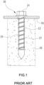
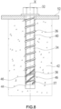
- FIG 1 illustrates a traditional concrete screw 10 including a shank 12, a head 14 formed at an end of the shank 12, and a thread 15 formed on the shank 12.
- the screw 10 is adapted to be fastened into a concrete structure 16 at the masonry (e.g., brick masonry) and/or concrete to join another structure component 18 on the concrete structure 16.
- a worker uses an electric drill (not shown in FIG 1 ) to drill a hole 19 in the concrete structure 16.
- the hole 19 has a hole diameter slightly greater than the shank diameter of the shank 12 but less than the major diameter of the thread 15.
- the head 14 is driven to rotate by a tool (not shown) such that the hole wall of the hole 19 is cut by the thread 15, and hence the shank 12 can be screwed into the hole 19 until the head 14 gets close to or abuts the structure component 18.
- a tool not shown
- plenty of concrete debris coming out of stiffened cement mortars (which are not compressed in contrast to rigid wooden fibers) in the concrete structure 16 cut by the thread 15 worsens the cutting force of the thread 15, retards movement of the shank 12 inside the hole 19, decelerates the screw 10 and even breaks the shank 12.
- the shank 12 driven into the hole 19 in the beginning may be shaken or even deviated.
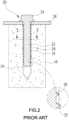
- FIGS. 2 and 3 illustrates another traditional concrete screw 20 including a shank 22, a head 24 formed at an end of the shank 22, and first and second threads 25 and 26 formed on the shank 22.
- the screw 20 is adapted to be fastened into a concrete structure 16 on which another structure component 28 is fixed.
- the second thread 26 features its major diameter less than the major diameter of the first thread 25 and almost equal to the hole diameter of the hole 19.
- the second thread 26 which bears against the inner surface of the hole 19 and supports cutting, accelerates the screw 20 moving inside the hole 19.
- concrete debris neither crushed nor dispersed fast by the second thread 26 imposes immense frictional resistances on the shank 22 at the time when sunk in the hole 19 deeply.
- the shank 22 fails in complete fastening, so that a greater screwing torque must be applied to overcome the resistances and hence probably break the shank 22 off. Moreover, the screw-in process of the shank 22 driven into the concrete structure 16 in the beginning cannot be stabilized by the added second thread 26. Because there is only one contact point between the hole wall and the second thread 26 on any cross section of the shank 22, the shank 22 newly driven into the concrete structure 16 is still shaken such that the screw 20 tends to deviate from the drive direction.
- the second thread 26 has auxiliary function to aid cutting but the debris cut off by the first thread 25 cannot be dispersed efficiently by the settlement of the second thread 26 and will keep accumulating between the threads and the hole wall, the hole wall inside the hole 19 on retrieval of the screw 20 is damaged by interactive frictions between the first and second threads 25, 26 and concrete debris directly or indirectly and fails to support pull-out strength through which the screw 20 is driven into the hole 19 again.
- an objective of the present invention is to provide a concrete screw according to claim 1 which is able to efficiently crush concrete debris and evenly disperse concrete debris around a shank of the concrete screw for accelerative movement of the concrete screw which is driven into a concrete structure, kept unshaken in the beginning, not deviated from a drive direction, and fastened stably and robustly.
- a screw of the present invention is adapted to be driven into a hole with a hole diameter in a concrete structure.
- the screw includes a head, a shank extending from the head and defining a longitudinal axis, a thread, and a plurality of oblique ribs.
- the shank includes a front segment and a rear segment spaced from the front segment along the longitudinal axis and located between the front segment and the head.
- the shank has a shank diameter less than the hole diameter of the hole.
- the front segment includes a front end having a flat end face.
- the thread is spirally formed on the shank and extends to the rear segment from the front segment.
- the thread includes a plurality of thread convolutions and has a major diameter greater than the hole diameter.
- At least three oblique ribs are formed on an outer periphery of the shank and located between any two adjacent thread convolutions of the thread at the rear segment and the front segment of the shank.
- the at least three oblique ribs are spaced around the shank circumferentially such that the front segment and the rear section of the shank respectively have at least three oblique ribs at cross-section.
- Each oblique rib has a trapezoid cross section with two lateral sides and a planar top face interconnecting the two lateral sides, and the planar top faces of the plurality of oblique ribs define the rib top diameter.
- the planar top faces of the at least three oblique ribs defines a rib top diameter less than the major diameter of the thread convolutions and slightly less than or equal to the hole diameter.
- the plurality of oblique ribs can quickly crush and disperse concrete debris which comes out of a hole wall of the hole cut by the thread when the concrete screw is driven into the hole.
- each oblique rib spirally extends along the longitudinal axis.
- three oblique ribs are designed between two adjacent thread convolutions at the front segment of the shank and spaced 120 degrees apart around the shank circumferentially, such that the front section of the shank has the three oblique ribs at cross-section.
- a plurality of notches is designed in the thread convolutions at the front segment of the shank for development of a plurality of teeth on the thread at the front segment.
- a concrete screw 30 according to a first embodiment is shown in FIGS. 4 through 8 of the drawings and generally includes a head 32, a shank 34 extending from the head 32, and a thread 36 formed on the shank 34.
- the shank 34 defining a longitudinal axis X includes a front segment 38 and a rear segment 40 spaced from the front segment 38 along the longitudinal axis X.
- the rear segment 40 is located between the front segment 38 and the head 32.
- the shank 34 has a shank diameter D.
- the front segment 38 and the rear segment 40 may have an identical shank diameter or distinct shank diameters, respectively.
- the head 32 is used to provide a torque tool (not shown in figures) in combination to apply rotational torque such that the shank 34 can be screwed inside a concrete structure 42.
- a hole 44 should be drilled inside the concrete structure 42 with an electric drill (not shown in figures) first for accommodating the shank 34 of the screw 30.
- the hole 44 has a hole diameter H which is greater than the shank diameter D of the shank 34.
- the thread 36 is spirally formed on an outer periphery of the shank 34 and extends from the front segment 38 toward the head 32. In this embodiment, the thread 36 extends to the rear segment 40 from a front end 45 of the front segment 38.
- the thread 36 includes a plurality of thread convolutions 37 and has a major diameter C that is greater than both the shank diameter D and the hole diameter H.
- the screw 30 further includes a plurality of oblique ribs 46 formed on the outer periphery of the shank 34 and spaced around the shank 34 circumferentially.
- Each oblique rib 46 is located between two adjacent thread convolutions 37 of the thread 36 and spirally extends along the longitudinal axis X.
- the front segment 38 of the shank 34 is provided with the plurality of oblique ribs 46 with any two oblique ribs 46 parallel to and spaced from each other.
- the rear segment 40 of the shank 34 is also provided with a plurality of oblique ribs 46.
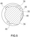
- three oblique ribs 46 are provided between any two adjacent thread convolutions 37 of the thread 36 at the front segment 38 and spaced 120 degrees apart around the shank 34 circumferentially. Accordingly, there are three oblique ribs 46 at any cross section in the front segment 38 of the shank 34, and each oblique rib 46 has a trapezoid cross section with two lateral sides 48 and a planar top face 50 (see FIG 5 ).
- the plurality of oblique ribs 46 have rib tops through which a rib top diameter R is defined.
- the rib top diameter R is less than the major diameter C and slightly less than or equal to the hole diameter H, that is, not greater than the hole diameter H of the hole 44.
- each oblique rib 46 is similar to an upward direction of the thread 36 extending toward the head 32 (upwardly and slantingly to the upper right).
- an inclined angle formed by each oblique rib 46 extending toward the head 32 relative to a horizontal axis perpendicular to the longitudinal axis X is greater than that of the thread 36 extending toward the head 32.
- the front end 45 of the shank 34 is inserted into the hole 44 in the concrete structure 42 as shown in FIG 6 .
- the major diameter of the thread convolutions 37 at the front end 45 is slightly less than the major diameter C of the thread convolutions 37 at the rear segment 40 for a modest torsion applied on the screw 30 in the beginning.
- the head 32 is driven to rotate by a torque tool (not shown in figures), and the shank 34 is smoothly screwed into the concrete structure 42 when concrete debris coming out of the hole wall of the hole 44 cut by the thread 36 is crushed by the oblique ribs 46 and dispersed around the shank 34 evenly.
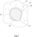
- the oblique ribs 46 act as the stirrer and grinder that distribute the debris on the shank 34 and even mill the debris into smaller pieces. This will mitigate the friction resistance in the whole screw-in process. Therefore, a structure component 52 can be fixed on the concrete structure 42. Because the separate oblique ribs 46 circumferentially arranged on the shank 34 form the rib top diameter R slightly less than or equal to the hole diameter H of the hole 44, there should be three contact planes formed between the hole wall and the three oblique ribs 46 at any cross section of the front segment 38 of the shank 34 which is being driven into the hole 44 in the beginning (see FIG 7 ). Accordingly, the shank 34 driven into the concrete structure 42 is kept unshaken at first and not deviated inside the concrete structure 42 deeply.
- the screw 30 of the present invention offers benefits over the concrete screw 20 in FIG. 2 as follows:
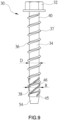
- FIG 9 illustrates the screw 30 in a second embodiment.
- a taper portion 54 extends from the front end 45 of the front segment 38, so that the front segment 38 of the shank 34 can be aligned with the hole 44 smoothly.
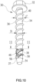
- FIGS. 10 and 11 illustrate the screw 30 in a third embodiment.
- a plurality of notches 56 is designed in the thread convolutions 37 at the front segment 38 for development of a plurality of teeth 58 on the thread 36 at the front segment 38.
- the teeth 58 support the plurality of oblique ribs 46 to expel concrete debris which is accommodated in the notches 56 for less friction on the shank 34 but higher speed of the screw 30 moved inside the concrete structure 42.
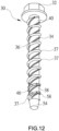
- FIG 12 illustrates the screw 30 in an embodiment of the present invention.
- the plurality of oblique ribs 46 provided on the shank 34 extends from the front segment 38 to the rear segment 40, so that at least three separate oblique ribs 46 are designed between any two adjacent thread convolutions 37 at the rear segment 40 of the shank 34 for crushing more concrete debris effectively.
Landscapes
- Engineering & Computer Science (AREA)
- General Engineering & Computer Science (AREA)
- Mechanical Engineering (AREA)
- Physics & Mathematics (AREA)
- Geometry (AREA)
- Joining Of Building Structures In Genera (AREA)
- Dowels (AREA)
- Connection Of Plates (AREA)
Claims (5)
- Schraube (30), die zum Eindrehen in ein vorgebohrtes Loch (44) mit einem Lochdurchmesser (H) in einer Betonkonstruktion (42) ausgelegt ist, wobei die Schraube (30) umfasst:einen Kopf (32);einen Schaft (34), der sich vom Kopf (32) erstreckt und eine Längsachse (X) definiert, wobei der Schaft (34) ein vorderes Segment (38) und ein hinteres Segment (40) umfasst, die von dem vorderen Segment (38) entlang der Längsachse (X) beabstandet und zwischen dem vorderen Segment (38) und dem Kopf (32) angeordnet sind, wobei der Schaft (34) einen Schaftdurchmesser (D) aufweist, der kleiner als der Lochdurchmesser (H) des Lochs (44) ist, wobei das vordere Segment (38) ein Vorderende (45) mit einer ebenen Endfläche aufweist; undein Gewinde (36), das spiralförmig auf dem Schaft (34) ausgebildet ist und sich vom vorderen Segment (38) zum hinteren Segment (40) in Richtung des Kopfes (32) erstreckt, wobei das Gewinde (36) mehrere Gewindewindungen (37) enthält und einen Außendurchmesser (C) aufweist, der größer als der Lochdurchmesser (H) ist;wobei mindestens drei schräge Rippen (46) auf einer Außenumfangsfläche des Schafts (34) ausgebildet und zwischen jeweils zwei benachbarten Gewindewindungen (37) des Gewindes (36) am hinteren Segment (40) und auch am vorderen Segment (38) des Schafts (34) angeordnet sind, wobei die mindestens drei schrägen Rippen (46) in Umfangsrichtung um den Schaft (34) herum so beabstandet sind, dass das vordere Segment (38) und der hintere Abschnitt (40) des Schafts (34) im Querschnitt jeweils mindestens drei schräge Rippen (46) aufweisen, wobei jede schräge Rippe (46) einen trapezförmigen Querschnitt mit zwei Seitenflächen (48) und einer ebenen Oberseite (50) aufweist, die die beiden Seitenflächen (48) verbindet, wobei die ebenen Oberseiten (50) der mindestens drei schrägen Rippen (46) einen oberen Rippendurchmesser (R) definieren, der kleiner als der Außendurchmesser (C) der Gewindewindungen (37) und geringfügig kleiner oder gleich dem Lochdurchmesser (H) ist, wobei die mindestens schrägen Rippen (46) Betonrückstände, die aus einer Lochwand des vorgebohrten Lochs (44) austreten und durch das Gewinde (36) geschnitten werden, wenn die Schraube (30) in das vorgebohrte Loch (44) eingedreht wird, zerkleinern und verteilen können.
- Schraube (30) nach Anspruch 1, wobei sich jede schräge Rippe (46) spiralförmig entlang der Längsachse (X) erstreckt.
- Schraube (30) nach Anspruch 2, wobei drei schräge Rippen (46) zwischen jeweils zwei benachbarten Gewindewindungen (37) des Gewindes (36) am vorderen Segment (38) des Schafts (34) ausgebildet und in Umfangsrichtung um den Schaft (34) herum um 120 Grad voneinander beabstandet sind, sodass der vordere Abschnitt (38) des Schafts (34) im Querschnitt die drei schrägen Rippen (46) aufweist.
- Schraube (30) nach Anspruch 1, wobei eine Vielzahl von Kerben (56) in den Gewindewindungen (37) des Gewindes (36) am vorderen Segment (38) zur Entwicklung einer Vielzahl von Zähnen (58) am Gewinde (36) des vorderen Segments (38) ausgebildet ist.
- Schraube (30) nach Anspruch 1, wobei eine nach oben gerichtete Erstreckungsrichtung jeder schrägen Rippe (46) ähnlich einer nach oben gerichteten Richtung des sich zum Kopf (32) hin erstreckenden Gewindes (36) ist.
Applications Claiming Priority (1)
| Application Number | Priority Date | Filing Date | Title |
|---|---|---|---|
| TW108102680A TWI706091B (zh) | 2019-01-24 | 2019-01-24 | 水泥螺絲 |
Publications (3)
| Publication Number | Publication Date |
|---|---|
| EP3686445A1 EP3686445A1 (de) | 2020-07-29 |
| EP3686445B1 true EP3686445B1 (de) | 2024-10-30 |
| EP3686445C0 EP3686445C0 (de) | 2024-10-30 |
Family
ID=68917407
Family Applications (1)
| Application Number | Title | Priority Date | Filing Date |
|---|---|---|---|
| EP19216249.3A Active EP3686445B1 (de) | 2019-01-24 | 2019-12-13 | Betonschraube |
Country Status (2)
| Country | Link |
|---|---|
| EP (1) | EP3686445B1 (de) |
| TW (1) | TWI706091B (de) |
Citations (1)
| Publication number | Priority date | Publication date | Assignee | Title |
|---|---|---|---|---|
| DE3420863C3 (de) * | 1983-06-22 | 1996-11-21 | Sfs Stadler Ag | Befestiger zum Fixieren von Dachbahnen auf weichem Isoliermaterial an einer festen Unterlage |
Family Cites Families (10)
| Publication number | Priority date | Publication date | Assignee | Title |
|---|---|---|---|---|
| US5957646A (en) * | 1998-11-02 | 1999-09-28 | Anthony C. Giannuzzi | Enhanced strength screw-type masonry anchor |
| TW542311U (en) * | 2002-04-17 | 2003-07-11 | Joker Ind Co Ltd | Retaining bolt with three-split screws capable of hiding external connecting retainers |
| DE102005039744A1 (de) * | 2005-08-23 | 2007-03-01 | Rensburg, Markus, Dipl.-Wirtsch.-Ing. | Schraube, insbesondere Holzsenkschraube, Distanzleiste und Verbundsystem |
| US20130039720A1 (en) * | 2011-08-11 | 2013-02-14 | Sheng-Tsai SHIH | Screw |
| US20130302111A1 (en) * | 2012-05-10 | 2013-11-14 | Sheng-Tsai SHIH | Concrete screw structure |
| US20130336744A1 (en) * | 2012-06-15 | 2013-12-19 | Infastech Intellectual Properties Pte. Ltd. | Threaded masonry fastener |
| DE102013203151A1 (de) * | 2013-02-26 | 2014-08-28 | Hilti Aktiengesellschaft | Betonschraube |
| TWM489214U (en) * | 2014-07-31 | 2014-11-01 | King Point Enterprise Co Ltd | Cement expansion bolt |
| CN107420403B (zh) * | 2016-05-23 | 2019-08-27 | 徐国泰 | 螺丝 |
| TWI614417B (zh) * | 2017-03-20 | 2018-02-11 | 甫商有限公司 | 具有切削凸牙的螺絲 |
-
2019
- 2019-01-24 TW TW108102680A patent/TWI706091B/zh active
- 2019-12-13 EP EP19216249.3A patent/EP3686445B1/de active Active
Patent Citations (1)
| Publication number | Priority date | Publication date | Assignee | Title |
|---|---|---|---|---|
| DE3420863C3 (de) * | 1983-06-22 | 1996-11-21 | Sfs Stadler Ag | Befestiger zum Fixieren von Dachbahnen auf weichem Isoliermaterial an einer festen Unterlage |
Also Published As
| Publication number | Publication date |
|---|---|
| EP3686445C0 (de) | 2024-10-30 |
| TWI706091B (zh) | 2020-10-01 |
| TW202028625A (zh) | 2020-08-01 |
| EP3686445A1 (de) | 2020-07-29 |
Similar Documents
| Publication | Publication Date | Title |
|---|---|---|
| US20200256372A1 (en) | Concrete Screw | |
| US10605289B2 (en) | Screw with cutting teeth | |
| US10247219B2 (en) | Screw-type fastener | |
| US5234299A (en) | Self-drilling anchor | |
| AU2010251791B2 (en) | Fastener and related method of use | |
| EP1371862B1 (de) | Selbstbohrender Befestiger | |
| EP3354912B1 (de) | Schraube | |
| EP0414335A1 (de) | Selbstbohrender Wanddübel | |
| US11137012B2 (en) | Wood screw | |
| JP5301939B2 (ja) | 固定素子 | |
| US20150316088A1 (en) | Screwcon | |
| CN101198798A (zh) | 用在混凝土中的螺钉 | |
| EP3249244B1 (de) | Schraube | |
| US10344789B2 (en) | Self-drilling drywall anchor and a method of securing an anchor in a drywall | |
| AU2022264702B2 (en) | Concrete fastener | |
| US5667348A (en) | Screw for fibrous boards | |
| EP3686445B1 (de) | Betonschraube | |
| US2959086A (en) | Wood screw having enlarged radial pips to facilitate entry into workpiece | |
| EP3855026B1 (de) | Schraube | |
| US11293475B2 (en) | Screw | |
| US20230392637A1 (en) | Concrete fastener | |
| JP7125874B2 (ja) | ねじ釘及び部材固定装置 | |
| EP3677800A1 (de) | Holzschraube | |
| EP0063570B1 (de) | Torsionsübertragungsvorrichtung | |
| AU669986B2 (en) | Improved self-drilling wall anchor |
Legal Events
| Date | Code | Title | Description |
|---|---|---|---|
| PUAI | Public reference made under article 153(3) epc to a published international application that has entered the european phase |
Free format text: ORIGINAL CODE: 0009012 |
|
| STAA | Information on the status of an ep patent application or granted ep patent |
Free format text: STATUS: THE APPLICATION HAS BEEN PUBLISHED |
|
| AK | Designated contracting states |
Kind code of ref document: A1 Designated state(s): AL AT BE BG CH CY CZ DE DK EE ES FI FR GB GR HR HU IE IS IT LI LT LU LV MC MK MT NL NO PL PT RO RS SE SI SK SM TR |
|
| AX | Request for extension of the european patent |
Extension state: BA ME |
|
| STAA | Information on the status of an ep patent application or granted ep patent |
Free format text: STATUS: REQUEST FOR EXAMINATION WAS MADE |
|
| 17P | Request for examination filed |
Effective date: 20210122 |
|
| RBV | Designated contracting states (corrected) |
Designated state(s): AL AT BE BG CH CY CZ DE DK EE ES FI FR GB GR HR HU IE IS IT LI LT LU LV MC MK MT NL NO PL PT RO RS SE SI SK SM TR |
|
| STAA | Information on the status of an ep patent application or granted ep patent |
Free format text: STATUS: EXAMINATION IS IN PROGRESS |
|
| 17Q | First examination report despatched |
Effective date: 20220818 |
|
| GRAP | Despatch of communication of intention to grant a patent |
Free format text: ORIGINAL CODE: EPIDOSNIGR1 |
|
| STAA | Information on the status of an ep patent application or granted ep patent |
Free format text: STATUS: GRANT OF PATENT IS INTENDED |
|
| INTG | Intention to grant announced |
Effective date: 20240704 |
|
| RAP3 | Party data changed (applicant data changed or rights of an application transferred) |
Owner name: HSU, MING-HAO Owner name: HSU, KUO-TAI |
|
| GRAS | Grant fee paid |
Free format text: ORIGINAL CODE: EPIDOSNIGR3 |
|
| GRAA | (expected) grant |
Free format text: ORIGINAL CODE: 0009210 |
|
| STAA | Information on the status of an ep patent application or granted ep patent |
Free format text: STATUS: THE PATENT HAS BEEN GRANTED |
|
| AK | Designated contracting states |
Kind code of ref document: B1 Designated state(s): AL AT BE BG CH CY CZ DE DK EE ES FI FR GB GR HR HU IE IS IT LI LT LU LV MC MK MT NL NO PL PT RO RS SE SI SK SM TR |
|
| REG | Reference to a national code |
Ref country code: GB Ref legal event code: FG4D |
|
| REG | Reference to a national code |
Ref country code: CH Ref legal event code: EP |
|
| REG | Reference to a national code |
Ref country code: DE Ref legal event code: R096 Ref document number: 602019061066 Country of ref document: DE |
|
| REG | Reference to a national code |
Ref country code: IE Ref legal event code: FG4D |
|
| U01 | Request for unitary effect filed |
Effective date: 20241107 |
|
| U07 | Unitary effect registered |
Designated state(s): AT BE BG DE DK EE FI FR IT LT LU LV MT NL PT RO SE SI Effective date: 20241115 |
|
| U20 | Renewal fee for the european patent with unitary effect paid |
Year of fee payment: 6 Effective date: 20241127 |
|
| PG25 | Lapsed in a contracting state [announced via postgrant information from national office to epo] |
Ref country code: HR Free format text: LAPSE BECAUSE OF FAILURE TO SUBMIT A TRANSLATION OF THE DESCRIPTION OR TO PAY THE FEE WITHIN THE PRESCRIBED TIME-LIMIT Effective date: 20241030 Ref country code: IS Free format text: LAPSE BECAUSE OF FAILURE TO SUBMIT A TRANSLATION OF THE DESCRIPTION OR TO PAY THE FEE WITHIN THE PRESCRIBED TIME-LIMIT Effective date: 20250228 |
|
| PG25 | Lapsed in a contracting state [announced via postgrant information from national office to epo] |
Ref country code: ES Free format text: LAPSE BECAUSE OF FAILURE TO SUBMIT A TRANSLATION OF THE DESCRIPTION OR TO PAY THE FEE WITHIN THE PRESCRIBED TIME-LIMIT Effective date: 20241030 |
|
| PG25 | Lapsed in a contracting state [announced via postgrant information from national office to epo] |
Ref country code: NO Free format text: LAPSE BECAUSE OF FAILURE TO SUBMIT A TRANSLATION OF THE DESCRIPTION OR TO PAY THE FEE WITHIN THE PRESCRIBED TIME-LIMIT Effective date: 20250130 |
|
| PG25 | Lapsed in a contracting state [announced via postgrant information from national office to epo] |
Ref country code: GR Free format text: LAPSE BECAUSE OF FAILURE TO SUBMIT A TRANSLATION OF THE DESCRIPTION OR TO PAY THE FEE WITHIN THE PRESCRIBED TIME-LIMIT Effective date: 20250131 |
|
| PG25 | Lapsed in a contracting state [announced via postgrant information from national office to epo] |
Ref country code: PL Free format text: LAPSE BECAUSE OF FAILURE TO SUBMIT A TRANSLATION OF THE DESCRIPTION OR TO PAY THE FEE WITHIN THE PRESCRIBED TIME-LIMIT Effective date: 20241030 |
|
| PG25 | Lapsed in a contracting state [announced via postgrant information from national office to epo] |
Ref country code: RS Free format text: LAPSE BECAUSE OF FAILURE TO SUBMIT A TRANSLATION OF THE DESCRIPTION OR TO PAY THE FEE WITHIN THE PRESCRIBED TIME-LIMIT Effective date: 20250130 |
|
| PG25 | Lapsed in a contracting state [announced via postgrant information from national office to epo] |
Ref country code: SM Free format text: LAPSE BECAUSE OF FAILURE TO SUBMIT A TRANSLATION OF THE DESCRIPTION OR TO PAY THE FEE WITHIN THE PRESCRIBED TIME-LIMIT Effective date: 20241030 |
|
| PG25 | Lapsed in a contracting state [announced via postgrant information from national office to epo] |
Ref country code: MC Free format text: LAPSE BECAUSE OF FAILURE TO SUBMIT A TRANSLATION OF THE DESCRIPTION OR TO PAY THE FEE WITHIN THE PRESCRIBED TIME-LIMIT Effective date: 20241030 |
|
| PG25 | Lapsed in a contracting state [announced via postgrant information from national office to epo] |
Ref country code: SK Free format text: LAPSE BECAUSE OF FAILURE TO SUBMIT A TRANSLATION OF THE DESCRIPTION OR TO PAY THE FEE WITHIN THE PRESCRIBED TIME-LIMIT Effective date: 20241030 |
|
| PG25 | Lapsed in a contracting state [announced via postgrant information from national office to epo] |
Ref country code: CZ Free format text: LAPSE BECAUSE OF FAILURE TO SUBMIT A TRANSLATION OF THE DESCRIPTION OR TO PAY THE FEE WITHIN THE PRESCRIBED TIME-LIMIT Effective date: 20241030 |
|
| REG | Reference to a national code |
Ref country code: CH Ref legal event code: PL |
|
| PLBE | No opposition filed within time limit |
Free format text: ORIGINAL CODE: 0009261 |
|
| STAA | Information on the status of an ep patent application or granted ep patent |
Free format text: STATUS: NO OPPOSITION FILED WITHIN TIME LIMIT |
|
| 26N | No opposition filed |
Effective date: 20250731 |
|
| PG25 | Lapsed in a contracting state [announced via postgrant information from national office to epo] |
Ref country code: CH Free format text: LAPSE BECAUSE OF NON-PAYMENT OF DUE FEES Effective date: 20241231 |
|
| PG25 | Lapsed in a contracting state [announced via postgrant information from national office to epo] |
Ref country code: IE Free format text: LAPSE BECAUSE OF NON-PAYMENT OF DUE FEES Effective date: 20241213 |
|
| U20 | Renewal fee for the european patent with unitary effect paid |
Year of fee payment: 7 Effective date: 20251118 |
|
| PGFP | Annual fee paid to national office [announced via postgrant information from national office to epo] |
Ref country code: GB Payment date: 20251201 Year of fee payment: 7 |