EP3686434A1 - Self-priming assembly for use in a multi-stage pump - Google Patents
Self-priming assembly for use in a multi-stage pump Download PDFInfo
- Publication number
- EP3686434A1 EP3686434A1 EP20153820.4A EP20153820A EP3686434A1 EP 3686434 A1 EP3686434 A1 EP 3686434A1 EP 20153820 A EP20153820 A EP 20153820A EP 3686434 A1 EP3686434 A1 EP 3686434A1
- Authority
- EP
- European Patent Office
- Prior art keywords
- diffuser
- arcuate
- axis
- self
- impeller
- Prior art date
- Legal status (The legal status is an assumption and is not a legal conclusion. Google has not performed a legal analysis and makes no representation as to the accuracy of the status listed.)
- Pending
Links
Images


Classifications
-
- F—MECHANICAL ENGINEERING; LIGHTING; HEATING; WEAPONS; BLASTING
- F04—POSITIVE - DISPLACEMENT MACHINES FOR LIQUIDS; PUMPS FOR LIQUIDS OR ELASTIC FLUIDS
- F04D—NON-POSITIVE-DISPLACEMENT PUMPS
- F04D29/00—Details, component parts, or accessories
- F04D29/40—Casings; Connections of working fluid
- F04D29/42—Casings; Connections of working fluid for radial or helico-centrifugal pumps
- F04D29/44—Fluid-guiding means, e.g. diffusers
- F04D29/445—Fluid-guiding means, e.g. diffusers especially adapted for liquid pumps
-
- F—MECHANICAL ENGINEERING; LIGHTING; HEATING; WEAPONS; BLASTING
- F04—POSITIVE - DISPLACEMENT MACHINES FOR LIQUIDS; PUMPS FOR LIQUIDS OR ELASTIC FLUIDS
- F04D—NON-POSITIVE-DISPLACEMENT PUMPS
- F04D1/00—Radial-flow pumps, e.g. centrifugal pumps; Helico-centrifugal pumps
- F04D1/06—Multi-stage pumps
-
- F—MECHANICAL ENGINEERING; LIGHTING; HEATING; WEAPONS; BLASTING
- F04—POSITIVE - DISPLACEMENT MACHINES FOR LIQUIDS; PUMPS FOR LIQUIDS OR ELASTIC FLUIDS
- F04D—NON-POSITIVE-DISPLACEMENT PUMPS
- F04D29/00—Details, component parts, or accessories
- F04D29/18—Rotors
- F04D29/22—Rotors specially for centrifugal pumps
-
- F—MECHANICAL ENGINEERING; LIGHTING; HEATING; WEAPONS; BLASTING
- F04—POSITIVE - DISPLACEMENT MACHINES FOR LIQUIDS; PUMPS FOR LIQUIDS OR ELASTIC FLUIDS
- F04D—NON-POSITIVE-DISPLACEMENT PUMPS
- F04D5/00—Pumps with circumferential or transverse flow
- F04D5/002—Regenerative pumps
-
- F—MECHANICAL ENGINEERING; LIGHTING; HEATING; WEAPONS; BLASTING
- F04—POSITIVE - DISPLACEMENT MACHINES FOR LIQUIDS; PUMPS FOR LIQUIDS OR ELASTIC FLUIDS
- F04D—NON-POSITIVE-DISPLACEMENT PUMPS
- F04D9/00—Priming; Preventing vapour lock
- F04D9/02—Self-priming pumps
Definitions
- a self-priming multi-stage pump In many fluid pumping applications it may be useful to have a self-priming multi-stage pump.
- Present approaches to priming a multi-stage pump incorporate secondary equipment. For instance, a separate diaphragm pump or a compressed air powered venturi/vacuum pump can be employed to prime the multi-stage pump.
- these types of systems not only require additional components, but can be costly and complex. Therefore, a self-priming pump that engages in the pumping action when called upon without requiring extensive secondary equipment or intervention by an operator to prime the pump is a more efficient approach to establishing prime and engaging the pumping action.
- the invention relates to multi-stage pumps and methods. Specifically, the invention relates to a self-priming assembly for use in multi-stage pumps.
- the self-priming assembly can have a first diffuser with a first central portion, a first diffuser axis, a first arcuate channel within the first central portion, and a first arcuate passage extending through the first central portion.
- the first arcuate channel and the first arcuate passage are concentric with each other about the first diffuser axis.
- a second diffuser with a second central portion, a second diffuser axis, a second arcuate channel within the second central portion, and a second arcuate passage extending through the second central portion can be included.
- the second arcuate channel and the second arcuate passage are concentric with each other about the second diffuser axis.
- An impeller with a plurality of chambers radially spaced around a hub and an impeller axis is also included.
- the first diffuser and the second diffuser are configured to be combined and receive the impeller therebetween with the first diffuser axis, the second diffuser axis, and the impeller axis aligned.
- Some embodiments include a self-priming assembly in which the first diffuser and the second diffuser are substantially identical.
- the impeller has an axle and the first diffuser and the second diffuser each have a through-hole configured to receive the axle.
- the first arcuate passage o can be located between the first arcuate channel and the first diffuser axis, and that the second arcuate passage can be located between the second arcuate channel and the second diffuser axis.
- the first arcuate channel can extend around the first diffuser axis approximately 5 ⁇ /3 radians (300 degrees) and the second arcuate channel can extend around the second diffuser axis approximately 5 ⁇ /3 radians (300 degrees).
- the first arcuate passage can extend around the first diffuser axis approximately 2 ⁇ /3 radians (120 degrees) and the second arcuate passage can extend around the second diffuser axis approximately 2 ⁇ /3 radians (120 degrees).
- first arcuate channel and the second arcuate channel each have a depth dimension, a width dimension, a first portion, a second portion, and a third portion, wherein each of the depth dimension and the width dimension is greater in the second portion than in the first and third portions.
- the depth dimension and the width dimension of the first arcuate channel and the second arcuate channel can gradually increase from the first portion to the second portion and can gradually decrease from the second portion to the third portion.
- first arcuate channel has a first length and the first arcuate passage can extend laterally along the first arcuate channel for less than a majority of the first length of the first arcuate channel
- second arcuate channel has a second length and the second arcuate can extend laterally along the second arcuate channel for less than a majority of the length of the second arcuate channel.
- each chamber of the plurality of chambers in the impeller is wedge-shaped. Further, each chamber of the plurality of chambers can extend around the impeller axis approximately ⁇ /6 radians (30 degrees).
- Another embodiment includes a multi-stage pump with an input member, an output member, a plurality of pump stage assemblies assembled along a pump axis, and a self-priming assembly with a first diffuser with a first diffuser axis, a second diffuser with a second diffuser axis configured to interface with the first diffuser, and an impeller with an impeller axis positioned between the first diffuser and the second diffuser and axially aligned with the first diffuser axis and the second diffuser axis.
- the self-priming assembly can be attached to the plurality of pump stage assemblies and axially aligned with the pump axis, and the plurality of pump stage assemblies and the self-priming assembly can be positioned between the input member and the output member.
- Other embodiments can be arranged in which the self-priming assembly is positioned adjacent to the output member.
- first diffuser and the second diffuser are identical, each with an arcuate channel and an arcuate passage concentric therewith.
- the arcuate channels of the first and second diffusers can have a length dimension and the arcuate passages can extend laterally along the arcuate channels for less than a majority of the length dimension. Further, the arcuate channels can have a depth dimension and a width dimension that change over the length dimension. In other embodiments, the arcuate channels can have a first portion, a second portion, and a third portion, and the depth dimension and the width dimension increase from the first portion to the second portion and decrease from the second portion to the third portion.
- an impeller having a hub and a plurality of chambers extending outward from the hub.
- the plurality of chambers can be substantially equally sized and wedge-shaped.
- each chamber of the plurality of chambers can extend around the impeller axis approximately ⁇ /6 radians (30 degrees).
- a multi-stage pump with a self-priming assembly configured to prime the multi-stage pump upon activation of the multi-stage pump.
- the context and particulars of this discussion are presented as examples only.
- embodiments of the disclosed invention can be configured in various ways, including different placement and more, fewer, and/or different parts within the multi-stage pump than are expressly presented below, such as a self-priming assembly positioned at any location among the plurality of pump stage assemblies, including before, after, or in-between.
- the self-priming assembly can be combined with one or multiple pump stage assemblies.
- a plurality of self-priming assemblies can be incorporated within a multi-stage pump.
- FIG. 1 illustrates an example multi-stage pump 10 incorporating an embodiment of a self-priming assembly 100 according to one embodiment of the invention.
- the multi-stage pump 10 includes an inlet member 12, an outlet member 14, and a plurality of pump stage assemblies 16 provided therebeteween.
- the plurality of pump stage assemblies 16 each generally contain an impeller and a diffuser assembly 18 that are axially aligned along a pump axis 20.
- Each of the plurality of pump stage assemblies 16 is configured to direct a fluid to the outermost portion of the diffuser 18 through the rotation of the impeller and the inertia of the fluid.
- Pressure within the multi-stage pump 10 progressively increases as the fluid travels through the plurality of pump stage assemblies 16 from the inlet member 12 to the outlet member 14.
- the self-priming assembly 100 is positioned between the ultimate (i.e., final or last) pump stage assembly 16A of the plurality of pump stage assemblies 16 and the outlet member 14 and is axially aligned with the plurality of pump stage assemblies 16 along the pump axis 20.
- the self-priming assembly 100 can also be positioned between the inlet member 12 and the plurality of pump stage assemblies 16 or in-between any two pump stage assemblies 16.
- multiple self-priming assemblies 100 can be incorporated and positioned at various locations throughout the multistage pump 10 ( e . g ., one positioned closest to the inlet member 12 and another positioned closest to the outlet member 14, two or more adjacent to the others and positioned at any stage position within the multi-stage pump 10, etc.).
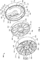
- the self-priming assembly 100 is shown in exploded form from various angles.
- the self-priming assembly 100 includes a first diffuser 110, a second diffuser 210, and an impeller 180 positioned between and within the first and second diffusers 110, 210.
- the first diffuser 110 and the second diffuser 210 can be substantially similar in every regard, including shape, size, and configuration, wherein like reference numbers represent like elements. This relationship not only simplifies the manufacturing process but also aids in assembly and functionality.
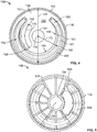
- the first diffuser 110 is shown.
- the second diffuser 210 is substantially similar to the first diffuser 110; therefore, for the sake of brevity the first and second diffusers 110, 210 will be described together.
- the first and second diffusers 110, 210 are defined by bodies 120, 220 that are substantially disc-shaped with a depth that extends along first and second diffuser axes 176, 276.
- Each of the bodies 120, 220 have a peripheral portion 130, 230 and a central portion 150, 250.
- the peripheral portions 130, 230 extend along and define the circumference of the bodies 120, 220 and have a first width 132, 232 for half of the circumference, a second width 134, 234 for the remaining half of the circumference, and an inner diameter 136, 236.
- the first width dimensions 132, 232 are each greater than the second width dimensions 134, 234, respectively, whereby the difference defines a first ledge 138, 238 and a second ledge 140, 240 along mating surfaces 142, 242.
- the central portions 150, 250 are adjacent to and bounded by the peripheral portions 130, 230 and have a central portion surface 152, 252 defining a central portion plane that is substantially perpendicular to the first and second diffuser axes 176, 276.
- the central portion surfaces 152, 252 are positioned inwards from the mating surface 142, 242 along the first and second diffuser axes 176, 276 a distance 174, 274 from the internal mating surface 142, 242 at the portion of the peripheral portion 130, 230 with the first width dimensions 132, 232.
- through-holes 154, 254 are provided in the central portions 150, 250 and centered on the first and second diffuser axes 176, 276.
- An arcuate channel 156, 256 is provided in the central portions 150, 250 between the through-hole 154, 254 and the peripheral portion 130, 230 and is substantially concentric, or concentric with both.
- the channels 156, 256 extend approximately 5 ⁇ /3 radians, or approximately 300 degrees, around the central portion surfaces 152, 252 and define channel lengths 160, 260 at a radial distances 172, 272 from the first and second diffuser axes 176, 276.
- the channels 156, 256 are continuous along the channel lengths 160, 260 and have a first portion 162, 262 adjacent to a second portion 164, 264, which is adjacent to a third portion 166 266.
- the channels 156, 256 each have a first depth dimension and a first width dimension at the first portion 162, 262, which both increase in depth and width as the channels 156, 256 extend from the first portion 162, 272 to the second portion 164, 264.
- the channels 156, 256 include a planar base surface 157, 257 with flared sidewalls 159, 259 and 161, 261 that extend away from the base surface 157, 257 in radially outer and inner directions respectively.
- the second depth dimension and second width dimension of the channels 156, 256 are maintained through the second portion 164, 264.
- the depth dimension and the width dimension of the channels 156, 256 gradually decrease back to approximately the first depth dimension and the first width dimension as the channels 156, 256 extend from the second portion 164, 264 the third portion 166, 266. While the example channels 156, 256 are illustrated with generally planar surfaces having linear or constant curvatures, the channels 156, 256 may define a variety of other form factors to impart application-specific flow dynamics.
- the passages 168, 268 are defined by an arcuate ellipse-like shape and extend through the central portion 150, 250.
- the passages 168, 268 are radially spaced between the first portion 162, 262 of the channels 156, 256 and the through-holes 154, 254, and are substantially concentric with both.
- the passages 168, 268 each extend along the central portions 150, 250 for approximately the same radians as the first portion 162, 262 of the channels 156, 256 (e.g., approximately 2 ⁇ /3 radians or 120 degrees), and define a passage length 170, 270.
- the radially inner sidewalls 161, 261 transition toward the base surface 157, 257 and into the passage 168, 268 proximate the first portion 162, 262 of the channel 156, 256.
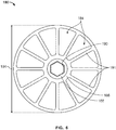
- the impeller 180 is shown in FIGS. 2 , 3 , and 6 .
- the impeller 180 is defined by an impeller body having an impeller depth 182, an impeller diameter 194, and a plurality of chambers 184 extending radially outward from and radially spaced around a hub 186.
- the hub 186 has an axle 188 extending axially outwardly from the hub 186 along an impeller axis 192.
- the axle 188 is configured to be received within the through-holes 154, 254 of the first and second diffusers 110, 210, respectively, when the self-priming assembly 10 is assembled.
- the impeller depth 182 is substantially similar to and preferably slightly less than an axial distance defined between the central portions 150, 250 when the respective first and second diffusers 110, 210 are coupled (shown in FIGS. 7 and 8 ).
- the impeller diameter 194 is preferably slightly less than the inner diameters 136, 236 of the peripheral portions 130, 230 of the first and second diffusers 110, 210.
- the impeller 180 is configured to be retained within and between the first and second diffusers 110, 210.
- the plurality of chambers 184 is wedge-shaped and is radially spaced around the hub 186.
- the axle 188 has an aperture 190 sized and configured to receive a drive shaft of the multi-stage pump 10.
- the plurality of chambers 184 are equally sized, with each chamber having an angular measurement of approximately ⁇ /6 radians, or 30 degrees.
- a plurality of planar spokes 191 extend radially outward from the hub 186. In other forms, the spokes 191 can define arcuate blades of varying cross-section and orientation to accommodate application-specific pumping performance.
- the impeller 180 rotates due to the engagement between the driveshaft of the multi-stage pump 10 and the axle 188 of the impeller 180. As shown in FIG. 7 the rotation of the impeller 180 is clockwise in the direction of arrow A and in FIG. 8 the impeller 180 is viewed as rotating counter-clockwise in the direction of arrow B. Fluid generally moves through the multi-stage pump 10 into the passage 168 in the first diffuser 110 and into at least one of the plurality of chambers 184 in the impeller 180. Because the first diffuser 110 and the second diffuser 210 are identical, when they are coupled together, as shown in FIGS.
- the first portion 162 of the first diffuser 110 aligns with the third portion 266 of the second diffuser 210.
- the third portion 166 of the first diffuser 110 aligns with the first portion 262 of the second diffuser 210. Accordingly, when fluid enters the self-priming assembly 100 through the passage 168, the fluid subsequently flows into the first portion 162 of the first diffuser 110 and the third portion 266 of the second diffuser 210. The rotation of the impeller 180 urges the fluid to the outermost portion of the plurality of chambers 184 and into the channels 156, 256 of the first and second diffusers 110, 210.
- This action causes the fluid to displace the air in the pump cavity and carry the air along with the fluid, which creates a vacuum.
- the fluid then travels along the second portions 164, 264 of the channels 156, 256 which comprise the deepest portions of channels 156, 256 and where the fluid is inhibited from entering or exiting the channels 156, 256.
- the fluid then enters the third portion 166 of channel 156 and the first portion 262 of channel 256, which are each more shallow in depth than the respective second portion 164, 264.
- the first portion 262 of channel 256 is where the transition 258 is located and the radially inner sidewall 261 tapers toward the passage 268.
- fluid is directed toward and out of the passage 268 of the second diffuser 210, and eventually out of the outlet member 14 of the multi-stage pump 10.
- first and second ledges 138, 140 of the first diffuser 110 abut the first and second ledges 238, 240 of the second diffuser 210, respectively.
- this arrangement prevents the first and second diffusers 110, 210 from rotating relative to each other as the self-priming assembly 100 experiences torque created by the rotation of the impeller 180 and movement of fluid through the self-priming assembly 100.
- Various alternative interlocking arrangements can be employed to rotationally couple the first and second diffusers 110, 210, such as external tabs that mate with a fixed external collar or housing.
- At least the self-priming assembly 100 contains fluid upon activation of the multi-stage pump 10 (e . g ., such as via an elbow or trap in fluid communication with the outlet member 14). Fluid in the plurality of chambers 184 aids in creating and maintaining a vacuum within the self-priming assembly 100 when the impeller 180 is initially rotated. The vacuum draws fluid through the plurality of pump stage assemblies 16 of the multi-stage pump 10 toward and through the self-priming assembly 100 and out the outlet member 14.
Abstract
Description
- This application claims priority under 35 U.S.C. §119 to United States Provisional Application No.
62/796,743 filed on January 25, 2019 - In many fluid pumping applications it may be useful to have a self-priming multi-stage pump. Present approaches to priming a multi-stage pump incorporate secondary equipment. For instance, a separate diaphragm pump or a compressed air powered venturi/vacuum pump can be employed to prime the multi-stage pump. However, these types of systems not only require additional components, but can be costly and complex. Therefore, a self-priming pump that engages in the pumping action when called upon without requiring extensive secondary equipment or intervention by an operator to prime the pump is a more efficient approach to establishing prime and engaging the pumping action.
- The invention relates to multi-stage pumps and methods. Specifically, the invention relates to a self-priming assembly for use in multi-stage pumps.
- Some of the embodiments provide a self-priming assembly for a multi-stage pump. The self-priming assembly can have a first diffuser with a first central portion, a first diffuser axis, a first arcuate channel within the first central portion, and a first arcuate passage extending through the first central portion. The first arcuate channel and the first arcuate passage are concentric with each other about the first diffuser axis. Additionally, a second diffuser with a second central portion, a second diffuser axis, a second arcuate channel within the second central portion, and a second arcuate passage extending through the second central portion can be included. The second arcuate channel and the second arcuate passage are concentric with each other about the second diffuser axis. An impeller with a plurality of chambers radially spaced around a hub and an impeller axis is also included. The first diffuser and the second diffuser are configured to be combined and receive the impeller therebetween with the first diffuser axis, the second diffuser axis, and the impeller axis aligned.
- Some embodiments include a self-priming assembly in which the first diffuser and the second diffuser are substantially identical. Other embodiments provide that the impeller has an axle and the first diffuser and the second diffuser each have a through-hole configured to receive the axle. Still other embodiments provide that the first arcuate passage o can be located between the first arcuate channel and the first diffuser axis, and that the second arcuate passage can be located between the second arcuate channel and the second diffuser axis. Some embodiments provide that the first arcuate channel can extend around the first diffuser axis approximately 5π/3 radians (300 degrees) and the second arcuate channel can extend around the second diffuser axis approximately 5π/3 radians (300 degrees). Some embodiments provide that the first arcuate passage can extend around the first diffuser axis approximately 2π/3 radians (120 degrees) and the second arcuate passage can extend around the second diffuser axis approximately 2π/3 radians (120 degrees).
- Other embodiments provide a self-priming assembly wherein the first arcuate channel and the second arcuate channel each have a depth dimension, a width dimension, a first portion, a second portion, and a third portion, wherein each of the depth dimension and the width dimension is greater in the second portion than in the first and third portions. The depth dimension and the width dimension of the first arcuate channel and the second arcuate channel can gradually increase from the first portion to the second portion and can gradually decrease from the second portion to the third portion. Additionally, the first arcuate channel has a first length and the first arcuate passage can extend laterally along the first arcuate channel for less than a majority of the first length of the first arcuate channel, and the second arcuate channel has a second length and the second arcuate can extend laterally along the second arcuate channel for less than a majority of the length of the second arcuate channel.
- Other embodiments provide a self-priming assembly in which the plurality of chambers in the impeller is wedge-shaped. Further, each chamber of the plurality of chambers can extend around the impeller axis approximately π/6 radians (30 degrees).
- Another embodiment includes a multi-stage pump with an input member, an output member, a plurality of pump stage assemblies assembled along a pump axis, and a self-priming assembly with a first diffuser with a first diffuser axis, a second diffuser with a second diffuser axis configured to interface with the first diffuser, and an impeller with an impeller axis positioned between the first diffuser and the second diffuser and axially aligned with the first diffuser axis and the second diffuser axis. The self-priming assembly can be attached to the plurality of pump stage assemblies and axially aligned with the pump axis, and the plurality of pump stage assemblies and the self-priming assembly can be positioned between the input member and the output member. Other embodiments can be arranged in which the self-priming assembly is positioned adjacent to the output member.
- Other embodiments of the invention can provide that the first diffuser and the second diffuser are identical, each with an arcuate channel and an arcuate passage concentric therewith. The arcuate channels of the first and second diffusers can have a length dimension and the arcuate passages can extend laterally along the arcuate channels for less than a majority of the length dimension. Further, the arcuate channels can have a depth dimension and a width dimension that change over the length dimension. In other embodiments, the arcuate channels can have a first portion, a second portion, and a third portion, and the depth dimension and the width dimension increase from the first portion to the second portion and decrease from the second portion to the third portion.
- Other embodiments include an impeller having a hub and a plurality of chambers extending outward from the hub. Additionally, the plurality of chambers can be substantially equally sized and wedge-shaped. Further, each chamber of the plurality of chambers can extend around the impeller axis approximately π/6 radians (30 degrees).
- Features which are described in the context of separate aspects and/or embodiments of the invention may be used together and/or be interchangeable wherever possible. Similarly, where features are, for brevity, described in the context of a single embodiment, those features may also be provided separately or in any suitable sub-combination. Features described in connection with the assembly or pump may have corresponding features definable and/or combinable with respect to a method or vice versa, and these embodiments are specifically envisaged.
- These and other features of the disclosure will become more apparent from the following description of the illustrative embodiments.
-
-
FIG. 1 is an isometric view of a multi-stage pump with a cover removed therefrom and exposing multiple pump stage assemblies and a self-priming assembly integrated therewith according to one embodiment; -
FIG. 2 is a front isometric exploded view of the self-priming assembly of the multi-stage pump shown inFIG. 1 ; -
FIG. 3 is a rear isometric exploded view of the self-priming assembly of the multi-stage pump shown inFIG. 1 ; -
FIG. 4 is a front elevational view of a diffuser plate of the multi-stage pump ofFIG. 1 according to one embodiment; -
FIG. 5 is a rear elevational view of the diffuser plate shown inFIG. 4 ; -
FIG. 6 is a front elevational view of an impeller of the multi-stage pump ofFIG. 1 , according to one embodiment; -
FIG. 7 is a front isometric view of the self-priming assembly of the multi-stage pump shown inFIG. 1 ; and -
FIG. 8 is a rear isometric view of the self-priming assembly of the multi-stage pump shown inFIG. 1 . - Corresponding reference characters indicate corresponding parts throughout the several views. Although the drawings represent embodiments of the disclosure, the drawings are not necessarily to scale and certain features may be exaggerated in order to better illustrate and explain the embodiments of the disclosure.
- Before any embodiments of the invention are explained in detail, it is to be understood that the invention is not limited in its application to the details of construction and the arrangement of components set forth in the following description or illustrated in the following drawings. The invention is capable of other embodiments and of being practiced or of being carried out in various ways. Also, it is to be understood that the phraseology and terminology used herein is for the purpose of description and should not be regarded as limiting. The use of "including," "comprising," or "having" and variations thereof herein is meant to encompass the items listed thereafter and equivalents thereof as well as additional items. Unless specified or limited otherwise, the terms "mounted," "connected," "supported," and "coupled" and variations thereof are used broadly and encompass both direct and indirect mountings, connections, supports, and couplings. Further, "connected" and "coupled" are not restricted to physical or mechanical connections or couplings.
- The following discussion is presented to enable a person skilled in the art to make and use embodiments of the invention. Various modifications to the illustrated embodiments will be readily apparent to those skilled in the art, and the generic principles herein can be applied to other embodiments and applications without departing from embodiments of the invention. Thus, embodiments of the invention are not intended to be limited to embodiments shown, but are to be accorded the widest scope consistent with the principles and features disclosed herein. The following detailed description is to be read with reference to the figures, in which like elements in different figures have like reference numerals. The figures, which are not necessarily to scale, depict selected embodiments and are not intended to limit the scope of embodiments of the invention. Skilled artisans will recognize the examples provided herein have many useful alternatives and fall within the scope of embodiments of the invention.
- Some of the disclosure below describes a multi-stage pump with a self-priming assembly configured to prime the multi-stage pump upon activation of the multi-stage pump. The context and particulars of this discussion are presented as examples only. For example, embodiments of the disclosed invention can be configured in various ways, including different placement and more, fewer, and/or different parts within the multi-stage pump than are expressly presented below, such as a self-priming assembly positioned at any location among the plurality of pump stage assemblies, including before, after, or in-between. As another example, the self-priming assembly can be combined with one or multiple pump stage assemblies. As a further example, a plurality of self-priming assemblies can be incorporated within a multi-stage pump.
-
FIG. 1 illustrates an examplemulti-stage pump 10 incorporating an embodiment of a self-primingassembly 100 according to one embodiment of the invention. Themulti-stage pump 10 includes aninlet member 12, anoutlet member 14, and a plurality ofpump stage assemblies 16 provided therebeteween. The plurality ofpump stage assemblies 16 each generally contain an impeller and adiffuser assembly 18 that are axially aligned along apump axis 20. Each of the plurality ofpump stage assemblies 16 is configured to direct a fluid to the outermost portion of thediffuser 18 through the rotation of the impeller and the inertia of the fluid. Pressure within themulti-stage pump 10 progressively increases as the fluid travels through the plurality ofpump stage assemblies 16 from theinlet member 12 to theoutlet member 14. - As shown in
FIG. 1 , the self-primingassembly 100 is positioned between the ultimate (i.e., final or last)pump stage assembly 16A of the plurality ofpump stage assemblies 16 and theoutlet member 14 and is axially aligned with the plurality ofpump stage assemblies 16 along thepump axis 20. However, as stated previously, in other embodiments the self-primingassembly 100 can also be positioned between theinlet member 12 and the plurality ofpump stage assemblies 16 or in-between any twopump stage assemblies 16. In still other embodiments, multiple self-primingassemblies 100 can be incorporated and positioned at various locations throughout the multistage pump 10 (e.g., one positioned closest to theinlet member 12 and another positioned closest to theoutlet member 14, two or more adjacent to the others and positioned at any stage position within themulti-stage pump 10, etc.). - Turning now to
FIGS. 2 and3 , the self-primingassembly 100 is shown in exploded form from various angles. The self-primingassembly 100 includes afirst diffuser 110, asecond diffuser 210, and animpeller 180 positioned between and within the first andsecond diffusers first diffuser 110 and thesecond diffuser 210 can be substantially similar in every regard, including shape, size, and configuration, wherein like reference numbers represent like elements. This relationship not only simplifies the manufacturing process but also aids in assembly and functionality. - With further reference to
FIGS. 4 and 5 , thefirst diffuser 110 is shown. As stated above, thesecond diffuser 210 is substantially similar to thefirst diffuser 110; therefore, for the sake of brevity the first andsecond diffusers - The first and
second diffusers bodies bodies peripheral portion central portion peripheral portions bodies first width second width inner diameter first width dimensions second width dimensions first ledge second ledge - The
central portions peripheral portions central portion surface mating surface distance internal mating surface peripheral portion first width dimensions holes central portions - An
arcuate channel central portions hole peripheral portion channels channel lengths - The
channels channel lengths first portion second portion third portion 166 266. Thechannels first portion channels first portion second portion channels planar base surface sidewalls base surface channels second portion channels channels second portion third portion example channels channels - The
passages central portion passages first portion channels holes passages central portions first portion channels 156, 256 (e.g., approximately 2π/3 radians or 120 degrees), and define apassage length transitions inner sidewalls base surface passage first portion channel - The
impeller 180 is shown inFIGS. 2 ,3 , and6 . Theimpeller 180 is defined by an impeller body having animpeller depth 182, animpeller diameter 194, and a plurality ofchambers 184 extending radially outward from and radially spaced around ahub 186. Thehub 186 has anaxle 188 extending axially outwardly from thehub 186 along animpeller axis 192. Theaxle 188 is configured to be received within the through-holes second diffusers assembly 10 is assembled. - The
impeller depth 182 is substantially similar to and preferably slightly less than an axial distance defined between thecentral portions second diffusers FIGS. 7 and 8 ). Theimpeller diameter 194 is preferably slightly less than theinner diameters peripheral portions second diffusers impeller 180 is configured to be retained within and between the first andsecond diffusers - The plurality of
chambers 184 is wedge-shaped and is radially spaced around thehub 186. Theaxle 188 has anaperture 190 sized and configured to receive a drive shaft of themulti-stage pump 10. The plurality ofchambers 184 are equally sized, with each chamber having an angular measurement of approximately π/6 radians, or 30 degrees. A plurality ofplanar spokes 191 extend radially outward from thehub 186. In other forms, thespokes 191 can define arcuate blades of varying cross-section and orientation to accommodate application-specific pumping performance. - In use, when the
multi-stage pump 10 is activated, theimpeller 180 rotates due to the engagement between the driveshaft of themulti-stage pump 10 and theaxle 188 of theimpeller 180. As shown inFIG. 7 the rotation of theimpeller 180 is clockwise in the direction of arrow A and inFIG. 8 theimpeller 180 is viewed as rotating counter-clockwise in the direction of arrow B. Fluid generally moves through themulti-stage pump 10 into thepassage 168 in thefirst diffuser 110 and into at least one of the plurality ofchambers 184 in theimpeller 180. Because thefirst diffuser 110 and thesecond diffuser 210 are identical, when they are coupled together, as shown inFIGS. 7 and 8 , thefirst portion 162 of thefirst diffuser 110 aligns with thethird portion 266 of thesecond diffuser 210. Similarly, thethird portion 166 of thefirst diffuser 110 aligns with thefirst portion 262 of thesecond diffuser 210. Accordingly, when fluid enters the self-primingassembly 100 through thepassage 168, the fluid subsequently flows into thefirst portion 162 of thefirst diffuser 110 and thethird portion 266 of thesecond diffuser 210. The rotation of theimpeller 180 urges the fluid to the outermost portion of the plurality ofchambers 184 and into thechannels second diffusers - The movement of fluid from the
passage 168 in thefirst diffuser 110 to the outermost portion of the plurality ofchambers 184 creates a low pressure to urge more fluid into the self-primingassembly 100. This action causes the fluid to displace the air in the pump cavity and carry the air along with the fluid, which creates a vacuum. The fluid then travels along thesecond portions channels channels channels impeller 180, the fluid then enters thethird portion 166 ofchannel 156 and thefirst portion 262 ofchannel 256, which are each more shallow in depth than the respectivesecond portion first portion 262 ofchannel 256 is where thetransition 258 is located and the radiallyinner sidewall 261 tapers toward thepassage 268. Thus, fluid is directed toward and out of thepassage 268 of thesecond diffuser 210, and eventually out of theoutlet member 14 of themulti-stage pump 10. - When assembled, the first and
second ledges first diffuser 110 abut the first andsecond ledges second diffuser 210, respectively. During use, this arrangement prevents the first andsecond diffusers assembly 100 experiences torque created by the rotation of theimpeller 180 and movement of fluid through the self-primingassembly 100. Various alternative interlocking arrangements can be employed to rotationally couple the first andsecond diffusers - It is preferable that at least the self-priming
assembly 100 contains fluid upon activation of the multi-stage pump 10 (e.g., such as via an elbow or trap in fluid communication with the outlet member 14). Fluid in the plurality ofchambers 184 aids in creating and maintaining a vacuum within the self-primingassembly 100 when theimpeller 180 is initially rotated. The vacuum draws fluid through the plurality ofpump stage assemblies 16 of themulti-stage pump 10 toward and through the self-primingassembly 100 and out theoutlet member 14. - It will be appreciated by those skilled in the art that while the invention has been described above in connection with particular embodiments and examples, the invention is not necessarily so limited, and that numerous other embodiments, examples, uses, modifications and departures from the embodiments, examples and uses are intended to be encompassed by the claims attached hereto. The entire disclosure of each patent and publication cited herein is incorporated by reference, as if each such patent or publication were individually incorporated by reference herein. Various features and advantages of the invention are set forth in the following claims.
- Features which are described in the context of separate embodiments may also be provided in combination in a single embodiment. Conversely, various features which are, for brevity, described in the context of a single embodiment, may also be provided separately or in any suitable sub-combination. The applicant hereby gives notice that new claims may be formulated to such features and/or combinations of such features during the prosecution of the present application or of any further application derived therefrom. Features of the assembly or pump described may be incorporated into/used in corresponding methods and vice versa.
- For the sake of completeness, it is also stated that the term "comprising" does not exclude other elements or steps, the term "a" or "an" does not exclude a plurality, and any reference signs in the claims shall not be construed as limiting the scope of the claims.
Claims (15)
- A self-priming assembly for a multi-stage pump, the self-priming assembly comprising:a first diffuser with a first central portion, a first diffuser axis, a first arcuate channel within the first central portion, and a first arcuate passage extending through the first central portion, wherein the first arcuate channel and the first arcuate passage are concentric with each other about the first diffuser axis;a second diffuser with a second central portion, a second diffuser axis, a second arcuate channel within the second central portion, and a second arcuate passage extending through the second central portion, wherein the second arcuate channel and the second arcuate passage are concentric with each other about the second diffuser axis; andan impeller with a plurality of chambers radially spaced around a hub and an impeller axis;wherein the first diffuser and the second diffuser are configured to be combined and receive the impeller therebetween with the first diffuser axis, the second diffuser axis, and the impeller axis aligned.
- The self-priming assembly of claim 1, wherein the first diffuser and the second diffuser are substantially identical.
- The self-priming assembly of claim 1 or claim 2, wherein the impeller has an axle and the first diffuser and the second diffuser each have a through-hole configured to receive the axle.
- The self-priming assembly of claim 1 or of claim 2 or claim 3, wherein the first arcuate passage is located between the first arcuate channel and the first diffuser axis, and the second arcuate passage is located between the second arcuate channel and the second diffuser axis.
- The self-priming assembly of claim 1 or of any of claims 2 to 4, wherein the first arcuate channel extends around the first diffuser axis approximately 5π/3 radians, and the second arcuate channel extends around the second diffuser axis approximately 5π/3 radians; or wherein the first arcuate passage extends around the first diffuser axis approximately 2π/3 radians, and the second arcuate passage extends around the second diffuser axis approximately 2π/3 radians.
- The self-priming assembly of claim 1 or of any of claims 2 to 5, wherein the first arcuate channel and the second arcuate channel each have a depth dimension, a width dimension, a first portion, a second portion, and a third portion, wherein each of the depth dimension and the width dimension is greater in the second portion than in the first portion and the third portion; and, optionally or preferably, wherein the depth dimension and the width dimension of the first arcuate channel and the second arcuate channel gradually increases from the first portion to the second portion and gradually decreases from the second portion to the third portion.
- The self-priming assembly of claim 1 or of any of claims 2 to 6, wherein the first arcuate channel has a first length and the first arcuate passage extends laterally along the first arcuate channel for less than a majority of the first length, and the second arcuate channel has a second length and the second arcuate passage extends laterally along the second arcuate channel for less than a majority of the second length.
- The self-priming assembly of claim 1 or of any of claims 2 to 7, wherein the plurality of chambers in the impeller are wedge-shaped; and, optionally or preferably, wherein each chamber of the plurality of chambers extends around the impeller axis approximately π/6 radians.
- A multi-stage pump comprising:an input member;an output member;a plurality of pump stage assemblies assembled along a pump axis; anda self-priming assembly with a first diffuser with a first diffuser axis, a second diffuser with a second diffuser axis configured to interface with the first diffuser, and an impeller with an impeller axis positioned between the first diffuser and the second diffuser and axially aligned with the first diffuser axis and the second diffuser axis;the self-priming assembly attached to the plurality of pump stage assemblies and axially aligned with the pump axis;the plurality of pump stage assemblies and the self-priming assembly positioned between the input member and the output member.
- The multi-stage pump of claim 9, wherein the self-priming assembly is positioned adjacent to the output member.
- The multi-stage pump of claim 9 or claim 10, wherein the first diffuser and the second diffuser are identical, each having an arcuate channel and an arcuate passage concentric therewith.
- The multi-stage pump of claim 11, wherein the arcuate channels of the first and second diffusers have a length dimension and the arcuate passages extend laterally along the arcuate channels for less than a majority of the length dimension.
- The multi-stage pump of claim 12, wherein the arcuate channels have a depth dimension and a width dimension that change over the length dimension; and optionally or preferably, wherein the arcuate channels have a first portion, a second portion, and a third portion, and the depth dimension and the width dimension increase from the first portion to the second portion and decrease from the second portion to the third portion.
- The multi-stage pump of claim 9 or of any of claims 10 to 13, wherein the impeller has a hub and a plurality of chambers extending outwardly from the hub.
- The multi-stage pump of claim 14, wherein the plurality of chambers are substantially equally sized and wedge-shaped, and, optionally or preferably, wherein each chamber of the plurality of chambers extends around the impeller axis approximately π/6 radians.
Applications Claiming Priority (1)
| Application Number | Priority Date | Filing Date | Title |
|---|---|---|---|
| US201962796743P | 2019-01-25 | 2019-01-25 |
Publications (1)
| Publication Number | Publication Date |
|---|---|
| EP3686434A1 true EP3686434A1 (en) | 2020-07-29 |
Family
ID=69326392
Family Applications (1)
| Application Number | Title | Priority Date | Filing Date |
|---|---|---|---|
| EP20153820.4A Pending EP3686434A1 (en) | 2019-01-25 | 2020-01-27 | Self-priming assembly for use in a multi-stage pump |
Country Status (2)
| Country | Link |
|---|---|
| US (2) | US11560902B2 (en) |
| EP (1) | EP3686434A1 (en) |
Citations (2)
| Publication number | Priority date | Publication date | Assignee | Title |
|---|---|---|---|---|
| DE888207C (en) * | 1951-08-10 | 1953-08-31 | Siemens Ag | Self-priming pump |
| JP2015140701A (en) * | 2014-01-28 | 2015-08-03 | 近畿金属株式会社 | self-priming pump |
Family Cites Families (74)
| Publication number | Priority date | Publication date | Assignee | Title |
|---|---|---|---|---|
| US1682331A (en) | 1928-08-28 | Pump system | ||
| US1920484A (en) | 1929-05-27 | 1933-08-01 | Slemon Otto | Rotary pump |
| US1971441A (en) | 1930-05-29 | 1934-08-28 | Laval Steam Turbine Co | Priming system for centrifugal pumps |
| US2006590A (en) | 1931-08-21 | 1935-07-02 | Westco Pump Corp | Pumping apparatus |
| US2386275A (en) | 1941-12-29 | 1945-10-09 | Sigmund Corp | Pumping arrangement |
| US2430509A (en) | 1943-11-06 | 1947-11-11 | Electrical Engineering And Mfg | Shaft seal for submersible pumps |
| FR911196A (en) | 1944-06-30 | 1946-07-01 | Self-priming centrifugal pump installation | |
| US2553066A (en) | 1944-06-30 | 1951-05-15 | Southern John | Self-priming centrifugal pump |
| GB621691A (en) | 1946-06-03 | 1949-04-14 | John William Ernest Ives | Improvements in or relating to deep suction pumps |
| GB691513A (en) | 1950-10-14 | 1953-05-13 | Alexander Sandor Sugar | Improvements in or relating to self-priming centrifugal pumps |
| US2696789A (en) | 1951-09-11 | 1954-12-14 | Alexander S Sugar | Self-priming centrifugal pump |
| US2674189A (en) | 1952-01-04 | 1954-04-06 | Dayton Pump & Mfg Co | Pumping system and method of operation |
| US2790393A (en) | 1952-03-29 | 1957-04-30 | Waterous Co | Priming valve assembly |
| US2841088A (en) | 1953-06-12 | 1958-07-01 | Francis E Daddario | Pumping unit |
| GB776635A (en) | 1954-11-24 | 1957-06-12 | Fabig Georg | Improvements relating to centrifugal pumps |
| US2810350A (en) | 1956-05-31 | 1957-10-22 | Flood City Brass & Electric Co | Automatic pumping system |
| US3007417A (en) | 1958-07-16 | 1961-11-07 | Goulds Pumps | Liquid ring pump |
| US3050008A (en) | 1958-12-30 | 1962-08-21 | Gilbert & Barker Mfg Co | Elimination of air and vapors from a centrifugal pump |
| US3082694A (en) | 1960-05-24 | 1963-03-26 | Ingersoll Rand Co | Self-priming centrifugal pump |
| US3093085A (en) | 1960-07-28 | 1963-06-11 | Ingersoll Rand Co | Self-priming pump |
| US3172549A (en) | 1962-08-23 | 1965-03-09 | Anthony Co | Tuck-away tail gate |
| JPS403655B1 (en) | 1962-11-20 | 1965-02-26 | ||
| US3151566A (en) | 1963-04-30 | 1964-10-06 | Rosenbauer Kg Konrad | Fluid handling apparatus |
| US3188974A (en) | 1963-06-21 | 1965-06-15 | Rosaen Filter Co | Fluid systems |
| DE1258738B (en) | 1964-10-07 | 1968-01-11 | Siemen & Hinsch Gmbh | Reversible side channel centrifugal pump |
| US3644061A (en) | 1969-07-31 | 1972-02-22 | Gorman Rupp Co | Pump apparatus |
| US3867070A (en) | 1973-06-28 | 1975-02-18 | Albert H Sloan | Jet water pump apparatus |
| US4067665A (en) | 1975-06-16 | 1978-01-10 | Schwartzman Everett H | Turbine booster pump system |
| US4035104A (en) | 1975-09-19 | 1977-07-12 | Ingersoll-Rand Company | Self-priming centrifugal pump |
| DE2757952C2 (en) | 1977-12-24 | 1983-02-24 | Sihi Gmbh & Co Kg, 2210 Itzehoe | Self-priming centrifugal pump |
| NZ197872A (en) | 1980-08-05 | 1985-03-20 | Sihi Gmbh & Co Kg | Self priming multi-stage centrifugal pump for liquids near boiling point |
| US4493607A (en) | 1982-12-16 | 1985-01-15 | Hudson Engineering Company | Tee-type valve for self-priming pump system |
| DE3425656C2 (en) | 1984-07-12 | 1994-12-08 | Sero Pumpenfabrik Gmbh | Centrifugal pump |
| US4780050A (en) | 1985-12-23 | 1988-10-25 | Sundstrand Corporation | Self-priming pump system |
| US4804313A (en) | 1987-03-24 | 1989-02-14 | Colt Industries Inc | Side channel self priming fuel pump having reservoir |
| US5035583A (en) | 1990-03-21 | 1991-07-30 | Smith & Loveless, Inc. | Sewage pump priming system |
| DE4221184A1 (en) | 1992-06-27 | 1994-01-05 | Bosch Gmbh Robert | Fuel delivery pump for vehicle IC engine - uses space between impeller and delivery channel to control direction of flow |
| US5401147A (en) | 1993-09-07 | 1995-03-28 | Ford Motor Company | Automotive fuel pump with convergent flow channel |
| US5536147A (en) | 1994-08-26 | 1996-07-16 | Paco Pumps, Inc. | Vacuum priming system for centrifugal pumps |
| NL9401455A (en) | 1994-09-07 | 1996-04-01 | Andre S J Van Coillie En Johan | Self-priming centrifugal pump-vacuum pump combination for, among other things, liquid fuels such as petrol, gasoil, kerozene, etc. with improved deaerator and integrated evaporation recovery option. |
| US5596970A (en) | 1996-03-28 | 1997-01-28 | Ford Motor Company | Fuel pump for an automotive fuel delivery system |
| DE19781894T1 (en) | 1996-07-26 | 1999-09-02 | Yokota Mfg | Self-priming centrifugal pump |
| US6071072A (en) * | 1998-12-02 | 2000-06-06 | Chang; Wan-Te | Self-priming centrifugal pump |
| US6409478B1 (en) | 1999-02-26 | 2002-06-25 | Roper Holdings, Inc. | Vacuum-assisted pump |
| US6315524B1 (en) | 1999-03-22 | 2001-11-13 | David Muhs | Pump system with vacuum source |
| US6692234B2 (en) | 1999-03-22 | 2004-02-17 | Water Management Systems | Pump system with vacuum source |
| KR20000066454A (en) | 1999-04-16 | 2000-11-15 | 지영배 | Vacuum suction pump |
| JP3638818B2 (en) | 1999-05-20 | 2005-04-13 | 愛三工業株式会社 | Wesco type pump |
| ITPD20010013A1 (en) | 2001-01-18 | 2002-07-18 | Dab Pumps Spa | FACILITATED SELF-PRIMING CENTRIFUGAL PUMP STRUCTURE. |
| ITFI20010116A1 (en) | 2001-06-26 | 2002-12-26 | Romeo Ramacciotti | SELF-PRIMING CENTRIFUGAL PUMP |
| US6926492B2 (en) | 2003-10-21 | 2005-08-09 | Chemgrout, Inc. | Suction housing for rotor/stator pump |
| US20050191185A1 (en) | 2003-12-31 | 2005-09-01 | Jones Garr M. | System and method for removing gases from liquid transport systems |
| US7520720B2 (en) | 2004-07-28 | 2009-04-21 | Sta-Rite Industries, Llc | Pump |
| US7331769B2 (en) | 2004-08-06 | 2008-02-19 | Smith & Loveless, Inc. | Pumping system |
| US7165932B2 (en) | 2005-01-24 | 2007-01-23 | Visteon Global Technologies, Inc. | Fuel pump having dual single sided impeller |
| US20070086906A1 (en) | 2005-10-14 | 2007-04-19 | Wayne Horley | Surface pump assembly |
| DE102005060895B4 (en) | 2005-12-20 | 2012-07-19 | Sero Pumpsystems Gmbh | Centrifugal pump for conveying hot and / or slightly outgassing and / or gas-laden media |
| WO2007133412A1 (en) | 2006-05-01 | 2007-11-22 | Continental Automotive Systems Us, Inc. | Fuel pump with inner channel priming |
| AU2008248134B2 (en) | 2007-05-04 | 2011-07-07 | Envirotech Pumpsystems, Inc. | Two-piece bearing housing for a centrifugal pump |
| US8043051B2 (en) * | 2007-05-23 | 2011-10-25 | Baker Hughes Incorporated | System, method, and apparatus for stackable multi-stage diffuser with anti-rotation lugs |
| KR100951430B1 (en) * | 2009-10-14 | 2010-04-06 | 조벽래 | Self sucking turbo pump |
| KR101173735B1 (en) | 2009-11-25 | 2012-08-13 | 박재욱 | Self priming pump |
| GB2477178B (en) * | 2010-02-18 | 2012-01-11 | Quail Res And Design Ltd | Improved Pump |
| EP2420677A1 (en) | 2010-08-18 | 2012-02-22 | Grundfos Management A/S | Multi-layer circulation pump |
| EP2505842B1 (en) * | 2011-03-29 | 2019-12-25 | Grundfos Management a/s | Multi stage centrifugal pump system |
| CN103827501B (en) | 2011-09-02 | 2016-09-07 | 瓦特尔斯 | For the pre-priming valve system starting centrifugal pump suction inlet |
| US10337516B2 (en) * | 2013-05-22 | 2019-07-02 | Grundfos Holding A/S | Multi-stage, self-priming centrifugal pump assembly |
| TWI589785B (en) | 2016-05-25 | 2017-07-01 | Pumping pump improved structure | |
| KR101711106B1 (en) | 2016-06-03 | 2017-02-28 | 주식회사 청우유체 | Super Self-priming pump |
| CA3047001C (en) * | 2017-02-13 | 2021-08-24 | Halliburton Energy Services, Inc. | Diffuser anti-rotation system and apparatus |
| US10161411B1 (en) | 2017-10-20 | 2018-12-25 | Halliburton Energy Services, Inc. | Centrifugal pump sealing surfaces |
| CA3091148C (en) * | 2018-05-15 | 2022-10-11 | Halliburton Energy Services, Inc. | Anti-spin pump diffuser |
| US20200309135A1 (en) | 2019-03-27 | 2020-10-01 | Baker Hughes, A Ge Company, Llc | High Flow and Low NPSHr Horizontal Pump with Priming Module |
| AU2021249219A1 (en) | 2020-04-03 | 2022-10-06 | Zodiac Pool Systems Llc | Swimming pool and spa pumps configured to improve priming performance |
-
2020
- 2020-01-27 EP EP20153820.4A patent/EP3686434A1/en active Pending
- 2020-01-27 US US16/773,110 patent/US11560902B2/en active Active
-
2023
- 2023-01-24 US US18/159,003 patent/US20230160397A1/en active Pending
Patent Citations (2)
| Publication number | Priority date | Publication date | Assignee | Title |
|---|---|---|---|---|
| DE888207C (en) * | 1951-08-10 | 1953-08-31 | Siemens Ag | Self-priming pump |
| JP2015140701A (en) * | 2014-01-28 | 2015-08-03 | 近畿金属株式会社 | self-priming pump |
Also Published As
| Publication number | Publication date |
|---|---|
| US20200240434A1 (en) | 2020-07-30 |
| US20230160397A1 (en) | 2023-05-25 |
| US11560902B2 (en) | 2023-01-24 |
Similar Documents
| Publication | Publication Date | Title |
|---|---|---|
| US3543368A (en) | Variable capacity fluid discharge device | |
| US5527149A (en) | Extended range regenerative pump with modified impeller and/or housing | |
| US20050152786A1 (en) | Turbo compressor | |
| EP1924772B1 (en) | Centrifugal blower for air handling equipment | |
| EP2136084B1 (en) | Centrifugal pump with segmented diffuser | |
| EP2912318B1 (en) | High efficiency low specific speed centrifugal pump | |
| US7217084B2 (en) | Automotive fuel pump with pressure balanced impeller | |
| US20100158679A1 (en) | Radial compressor | |
| EP2372162A2 (en) | Pump impeller | |
| US10907647B2 (en) | Centrifugal pump with serrated impeller | |
| EP3686434A1 (en) | Self-priming assembly for use in a multi-stage pump | |
| CN107208544A (en) | Booster | |
| EP3601802B1 (en) | Magnetically engaged pump | |
| CN106232996B (en) | General housing for centrifugal gas compressor | |
| JP6850790B2 (en) | Centrifugal pump | |
| US20220106957A1 (en) | Vane pump device | |
| US10060436B2 (en) | Progressive vortex pump | |
| JP2007162483A (en) | Cascade pump | |
| RU2677308C2 (en) | Intake channel arrangement for a volute casing of a centrifugal pump, a flange member, a volute casing for a centrifugal pump and a centrifugal pump | |
| US20180142653A1 (en) | Fuel pump | |
| CN218151510U (en) | Multi-stage fan | |
| KR102460339B1 (en) | Impeller for leak blocking and Blower using the impeller | |
| JPH025798A (en) | Diffuser of multiple stage centrifugal hydraulic machine | |
| EP2060791A1 (en) | Centrifugal electric pump with axial suction | |
| EP2532896A2 (en) | Pumping device |
Legal Events
| Date | Code | Title | Description |
|---|---|---|---|
| PUAI | Public reference made under article 153(3) epc to a published international application that has entered the european phase |
Free format text: ORIGINAL CODE: 0009012 |
|
| STAA | Information on the status of an ep patent application or granted ep patent |
Free format text: STATUS: THE APPLICATION HAS BEEN PUBLISHED |
|
| AK | Designated contracting states |
Kind code of ref document: A1 Designated state(s): AL AT BE BG CH CY CZ DE DK EE ES FI FR GB GR HR HU IE IS IT LI LT LU LV MC MK MT NL NO PL PT RO RS SE SI SK SM TR |
|
| AX | Request for extension of the european patent |
Extension state: BA ME |
|
| RIN1 | Information on inventor provided before grant (corrected) |
Inventor name: HERMES, JEFF Inventor name: WIYNINGER, BRAD Inventor name: BEILKE, DANIEL ALLAN Inventor name: MCELWAIN, ELI |
|
| STAA | Information on the status of an ep patent application or granted ep patent |
Free format text: STATUS: REQUEST FOR EXAMINATION WAS MADE |
|
| 17P | Request for examination filed |
Effective date: 20210129 |
|
| RBV | Designated contracting states (corrected) |
Designated state(s): AL AT BE BG CH CY CZ DE DK EE ES FI FR GB GR HR HU IE IS IT LI LT LU LV MC MK MT NL NO PL PT RO RS SE SI SK SM TR |
|
| STAA | Information on the status of an ep patent application or granted ep patent |
Free format text: STATUS: EXAMINATION IS IN PROGRESS |
|
| 17Q | First examination report despatched |
Effective date: 20220303 |